EP3699521B1 - Réfrigérateur d'entrée - Google Patents
Réfrigérateur d'entrée Download PDFInfo
- Publication number
- EP3699521B1 EP3699521B1 EP20158916.5A EP20158916A EP3699521B1 EP 3699521 B1 EP3699521 B1 EP 3699521B1 EP 20158916 A EP20158916 A EP 20158916A EP 3699521 B1 EP3699521 B1 EP 3699521B1
- Authority
- EP
- European Patent Office
- Prior art keywords
- drain
- storage compartment
- cabinet
- refrigerator according
- port
- Prior art date
- Legal status (The legal status is an assumption and is not a legal conclusion. Google has not performed a legal analysis and makes no representation as to the accuracy of the status listed.)
- Active
Links
Images




Classifications
-
- F—MECHANICAL ENGINEERING; LIGHTING; HEATING; WEAPONS; BLASTING
- F25—REFRIGERATION OR COOLING; COMBINED HEATING AND REFRIGERATION SYSTEMS; HEAT PUMP SYSTEMS; MANUFACTURE OR STORAGE OF ICE; LIQUEFACTION SOLIDIFICATION OF GASES
- F25D—REFRIGERATORS; COLD ROOMS; ICE-BOXES; COOLING OR FREEZING APPARATUS NOT OTHERWISE PROVIDED FOR
- F25D23/00—General constructional features
- F25D23/10—Arrangements for mounting in particular locations, e.g. for built-in type, for corner type
-
- F—MECHANICAL ENGINEERING; LIGHTING; HEATING; WEAPONS; BLASTING
- F25—REFRIGERATION OR COOLING; COMBINED HEATING AND REFRIGERATION SYSTEMS; HEAT PUMP SYSTEMS; MANUFACTURE OR STORAGE OF ICE; LIQUEFACTION SOLIDIFICATION OF GASES
- F25D—REFRIGERATORS; COLD ROOMS; ICE-BOXES; COOLING OR FREEZING APPARATUS NOT OTHERWISE PROVIDED FOR
- F25D21/00—Defrosting; Preventing frosting; Removing condensed or defrost water
- F25D21/14—Collecting or removing condensed and defrost water; Drip trays
-
- F—MECHANICAL ENGINEERING; LIGHTING; HEATING; WEAPONS; BLASTING
- F25—REFRIGERATION OR COOLING; COMBINED HEATING AND REFRIGERATION SYSTEMS; HEAT PUMP SYSTEMS; MANUFACTURE OR STORAGE OF ICE; LIQUEFACTION SOLIDIFICATION OF GASES
- F25B—REFRIGERATION MACHINES, PLANTS OR SYSTEMS; COMBINED HEATING AND REFRIGERATION SYSTEMS; HEAT PUMP SYSTEMS
- F25B21/00—Machines, plants or systems, using electric or magnetic effects
- F25B21/02—Machines, plants or systems, using electric or magnetic effects using Peltier effect; using Nernst-Ettinghausen effect
-
- F—MECHANICAL ENGINEERING; LIGHTING; HEATING; WEAPONS; BLASTING
- F25—REFRIGERATION OR COOLING; COMBINED HEATING AND REFRIGERATION SYSTEMS; HEAT PUMP SYSTEMS; MANUFACTURE OR STORAGE OF ICE; LIQUEFACTION SOLIDIFICATION OF GASES
- F25D—REFRIGERATORS; COLD ROOMS; ICE-BOXES; COOLING OR FREEZING APPARATUS NOT OTHERWISE PROVIDED FOR
- F25D17/00—Arrangements for circulating cooling fluids; Arrangements for circulating gas, e.g. air, within refrigerated spaces
- F25D17/04—Arrangements for circulating cooling fluids; Arrangements for circulating gas, e.g. air, within refrigerated spaces for circulating air, e.g. by convection
- F25D17/042—Air treating means within refrigerated spaces
- F25D17/045—Air flow control arrangements
-
- F—MECHANICAL ENGINEERING; LIGHTING; HEATING; WEAPONS; BLASTING
- F25—REFRIGERATION OR COOLING; COMBINED HEATING AND REFRIGERATION SYSTEMS; HEAT PUMP SYSTEMS; MANUFACTURE OR STORAGE OF ICE; LIQUEFACTION SOLIDIFICATION OF GASES
- F25D—REFRIGERATORS; COLD ROOMS; ICE-BOXES; COOLING OR FREEZING APPARATUS NOT OTHERWISE PROVIDED FOR
- F25D17/00—Arrangements for circulating cooling fluids; Arrangements for circulating gas, e.g. air, within refrigerated spaces
- F25D17/04—Arrangements for circulating cooling fluids; Arrangements for circulating gas, e.g. air, within refrigerated spaces for circulating air, e.g. by convection
- F25D17/06—Arrangements for circulating cooling fluids; Arrangements for circulating gas, e.g. air, within refrigerated spaces for circulating air, e.g. by convection by forced circulation
- F25D17/08—Arrangements for circulating cooling fluids; Arrangements for circulating gas, e.g. air, within refrigerated spaces for circulating air, e.g. by convection by forced circulation using ducts
-
- F—MECHANICAL ENGINEERING; LIGHTING; HEATING; WEAPONS; BLASTING
- F25—REFRIGERATION OR COOLING; COMBINED HEATING AND REFRIGERATION SYSTEMS; HEAT PUMP SYSTEMS; MANUFACTURE OR STORAGE OF ICE; LIQUEFACTION SOLIDIFICATION OF GASES
- F25D—REFRIGERATORS; COLD ROOMS; ICE-BOXES; COOLING OR FREEZING APPARATUS NOT OTHERWISE PROVIDED FOR
- F25D23/00—General constructional features
- F25D23/02—Doors; Covers
-
- F—MECHANICAL ENGINEERING; LIGHTING; HEATING; WEAPONS; BLASTING
- F25—REFRIGERATION OR COOLING; COMBINED HEATING AND REFRIGERATION SYSTEMS; HEAT PUMP SYSTEMS; MANUFACTURE OR STORAGE OF ICE; LIQUEFACTION SOLIDIFICATION OF GASES
- F25D—REFRIGERATORS; COLD ROOMS; ICE-BOXES; COOLING OR FREEZING APPARATUS NOT OTHERWISE PROVIDED FOR
- F25D23/00—General constructional features
- F25D23/02—Doors; Covers
- F25D23/028—Details
-
- F—MECHANICAL ENGINEERING; LIGHTING; HEATING; WEAPONS; BLASTING
- F25—REFRIGERATION OR COOLING; COMBINED HEATING AND REFRIGERATION SYSTEMS; HEAT PUMP SYSTEMS; MANUFACTURE OR STORAGE OF ICE; LIQUEFACTION SOLIDIFICATION OF GASES
- F25D—REFRIGERATORS; COLD ROOMS; ICE-BOXES; COOLING OR FREEZING APPARATUS NOT OTHERWISE PROVIDED FOR
- F25D29/00—Arrangement or mounting of control or safety devices
-
- F—MECHANICAL ENGINEERING; LIGHTING; HEATING; WEAPONS; BLASTING
- F25—REFRIGERATION OR COOLING; COMBINED HEATING AND REFRIGERATION SYSTEMS; HEAT PUMP SYSTEMS; MANUFACTURE OR STORAGE OF ICE; LIQUEFACTION SOLIDIFICATION OF GASES
- F25D—REFRIGERATORS; COLD ROOMS; ICE-BOXES; COOLING OR FREEZING APPARATUS NOT OTHERWISE PROVIDED FOR
- F25D29/00—Arrangement or mounting of control or safety devices
- F25D29/005—Mounting of control devices
-
- F—MECHANICAL ENGINEERING; LIGHTING; HEATING; WEAPONS; BLASTING
- F25—REFRIGERATION OR COOLING; COMBINED HEATING AND REFRIGERATION SYSTEMS; HEAT PUMP SYSTEMS; MANUFACTURE OR STORAGE OF ICE; LIQUEFACTION SOLIDIFICATION OF GASES
- F25B—REFRIGERATION MACHINES, PLANTS OR SYSTEMS; COMBINED HEATING AND REFRIGERATION SYSTEMS; HEAT PUMP SYSTEMS
- F25B2321/00—Details of machines, plants or systems, using electric or magnetic effects
- F25B2321/02—Details of machines, plants or systems, using electric or magnetic effects using Peltier effects; using Nernst-Ettinghausen effects
- F25B2321/023—Mounting details thereof
-
- F—MECHANICAL ENGINEERING; LIGHTING; HEATING; WEAPONS; BLASTING
- F25—REFRIGERATION OR COOLING; COMBINED HEATING AND REFRIGERATION SYSTEMS; HEAT PUMP SYSTEMS; MANUFACTURE OR STORAGE OF ICE; LIQUEFACTION SOLIDIFICATION OF GASES
- F25B—REFRIGERATION MACHINES, PLANTS OR SYSTEMS; COMBINED HEATING AND REFRIGERATION SYSTEMS; HEAT PUMP SYSTEMS
- F25B25/00—Machines, plants or systems, using a combination of modes of operation covered by two or more of the groups F25B1/00 - F25B23/00
- F25B25/02—Compression-sorption machines, plants, or systems
-
- F—MECHANICAL ENGINEERING; LIGHTING; HEATING; WEAPONS; BLASTING
- F25—REFRIGERATION OR COOLING; COMBINED HEATING AND REFRIGERATION SYSTEMS; HEAT PUMP SYSTEMS; MANUFACTURE OR STORAGE OF ICE; LIQUEFACTION SOLIDIFICATION OF GASES
- F25D—REFRIGERATORS; COLD ROOMS; ICE-BOXES; COOLING OR FREEZING APPARATUS NOT OTHERWISE PROVIDED FOR
- F25D2317/00—Details or arrangements for circulating cooling fluids; Details or arrangements for circulating gas, e.g. air, within refrigerated spaces, not provided for in other groups of this subclass
- F25D2317/04—Treating air flowing to refrigeration compartments
-
- F—MECHANICAL ENGINEERING; LIGHTING; HEATING; WEAPONS; BLASTING
- F25—REFRIGERATION OR COOLING; COMBINED HEATING AND REFRIGERATION SYSTEMS; HEAT PUMP SYSTEMS; MANUFACTURE OR STORAGE OF ICE; LIQUEFACTION SOLIDIFICATION OF GASES
- F25D—REFRIGERATORS; COLD ROOMS; ICE-BOXES; COOLING OR FREEZING APPARATUS NOT OTHERWISE PROVIDED FOR
- F25D2321/00—Details or arrangements for defrosting; Preventing frosting; Removing condensed or defrost water, not provided for in other groups of this subclass
- F25D2321/14—Collecting condense or defrost water; Removing condense or defrost water
- F25D2321/144—Collecting condense or defrost water; Removing condense or defrost water characterised by the construction of drip water collection pans
- F25D2321/1441—Collecting condense or defrost water; Removing condense or defrost water characterised by the construction of drip water collection pans inside a refrigerator
-
- F—MECHANICAL ENGINEERING; LIGHTING; HEATING; WEAPONS; BLASTING
- F25—REFRIGERATION OR COOLING; COMBINED HEATING AND REFRIGERATION SYSTEMS; HEAT PUMP SYSTEMS; MANUFACTURE OR STORAGE OF ICE; LIQUEFACTION SOLIDIFICATION OF GASES
- F25D—REFRIGERATORS; COLD ROOMS; ICE-BOXES; COOLING OR FREEZING APPARATUS NOT OTHERWISE PROVIDED FOR
- F25D2323/00—General constructional features not provided for in other groups of this subclass
- F25D2323/02—Details of doors or covers not otherwise covered
-
- F—MECHANICAL ENGINEERING; LIGHTING; HEATING; WEAPONS; BLASTING
- F25—REFRIGERATION OR COOLING; COMBINED HEATING AND REFRIGERATION SYSTEMS; HEAT PUMP SYSTEMS; MANUFACTURE OR STORAGE OF ICE; LIQUEFACTION SOLIDIFICATION OF GASES
- F25D—REFRIGERATORS; COLD ROOMS; ICE-BOXES; COOLING OR FREEZING APPARATUS NOT OTHERWISE PROVIDED FOR
- F25D2700/00—Means for sensing or measuring; Sensors therefor
Definitions
- the present disclosure relates to a refrigerator installed at an entrance of a building, such as a home or a business.
- a delivery vehicle is provided with a refrigerator or a warmer to store and deliver the food so as to prevent the food from spoiling or cooling.
- the food is packed in a packaging material and delivered so as to keep the food cool or warm, depending on the type of food.
- the packaging material is often composed of environmental pollutants such as polystyrene foam.
- the social atmosphere recently has placed an emphasis on a reduction of an amount of packaging material used.
- the delivery person may deliver the food to the user in a face-to-face manner.
- the user is not at home or when the delivery time is too early or too late, it is difficult for the delivery person to deliver the food in a face-to-face manner.
- a product has been introduced in which a refrigerator is installed at an entrance (e.g. a front door) of a predetermined place, so that a delivery person can deliver the food into the refrigerator in order to keep the food fresh until a user can receive the food by accessing the refrigerator at a convenient time.
- Korean Patent Application Publication No. 2011-0033394 discloses an entrance refrigerator mounted on a front door.
- WO 97/41542 A1 discloses an entrance refrigerator according to the preamble of claim 1.
- an animal trapped in the storage compartment may die due to a lack of oxygen and a decrease in body temperature.
- An object of the present disclosure is to provide an entrance refrigerator capable of preventing a lack of oxygen in a storage compartment from occurring if a companion animal is trapped in the storage compartment.
- an entrance refrigerator which comprises: a cabinet installed to pass through or inserted into a door or a wall, defining a storage compartment for storing goods therein, and having a drain hole at a bottom of the storage compartment; a drain port extending from a bottom surface of the cabinet and communicating with the drain hole; a housing coupled to or formed integrally with a lower part of the cabinet; an outdoor side door configured to open or close a front side of the storage compartment and exposed to an outside of a space, the door or the wall being a boundary of the space; an indoor side door to open or close a rear side of the storage compartment and exposed to an inside the space; a cold air supply device, at least a part of which is disposed in the housing, configured to make air in the storage compartment cold; an actuator provided to selectively open or close an opening formed in the drain port; and a controller configured to control operations of the cold air supply device and the actuator.
- the drain port In the entrance refrigerator, when a living organism such as a companion animal is detected in the storage compartment, the drain port is opened, such that air outside the storage compartment flows into the storage compartment through the drain port.
- the actuator may comprise a plunger configured to perform a linear reciprocating motion; and a driver configured to provide driving force enabling the linear reciprocating motion of the plunger.
- the driver may comprise a solenoid, or a motor and a gear assembly configured to transmit rotational force of the motor to the plunger.
- the opening may be an air hole formed at a point between an upper end and a lower end of the drain port.
- the air hole may be selectively opened or closed by an end portion of the plunger which performs the linear reciprocating motion substantially in a horizontal direction.
- the entrance refrigerator may further comprise a drain box provided below the cabinet to store condensed water discharged through the drain port.
- the drain box may comprise a port receiver protruding from a bottom of the drain box.
- a recessed portion that the condense water can fill is formed in an upper end of the port receiver at a predetermined depth. The lower end of the drain port may be accommodated in the recessed portion.
- a carbon dioxide sensor for detecting the concentration of carbon dioxide discharged by the companion animal or a motion sensor for detecting the motion of the companion animal may be mounted inside the storage compartment.
- an air hole may be formed on the side surface of the drain port to be selectively opened or closed by an actuator.
- the actuator which selectively opens or closes the air hole, may include a driver and a plunger which performs a linear reciprocating motion by the driver, so that the end of the plunger may selectively open or close the air hole.
- the actuator may be driven to open the air hole.
- a drain cover for shielding a condensed water discharge port formed in the lower end of the drain port may be provided, and the drain cover may allow the actuator to selectively open the condensed water discharge port.
- the controller may allow the plunger of the actuator to press down a shielding plate constituting the drain cover, such that the condensed water discharge port is opened.
- the condensed water discharge port may be opened by rotation of the shielding plate due to the load of the condensed water collected in the drain port.
- the shielding plate may be restored to an original position by a restoring force of a torsion spring mounted on a rotational shaft of the shielding plate.
- the entrance refrigerator configured as described above according to the embodiment has the following effects.
- a condensed water flow passage provided for discharging condensed water generated in the bottom of the storage compartment or a cold sink of a thermoelectric module may be opened.
- the driving of the cold air supply device may be controlled to adjust the temperature of the storage compartment. Therefore, an occurrence in which the companion animal dies due to hypothermia may be prevented.
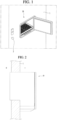
- the entrance refrigerator 10 is mounted by passing through a suitably-sized opening in a front door 1 or a front wall of a house.
- the entrance refrigerator 10 may be mounted at a point spaced apart from a knob 2 of the front door 1, for example, the entrance refrigerator 10 may be mounted at the center of the front door 1.
- the entrance refrigerator 10 is preferably installed at a height within two meters from the bottom of the front door 1 for convenience of a user and for convenience to a delivery person who delivers goods to the entrance refrigerator 10.
- the entrance refrigerator 10 may be installed at a height in a range of 1.5 meters to 1.7 meters from the bottom of the front door 1.
- the entrance refrigerator 10 is exposed to the outside O (outdoors), and another portion of the entrance refrigerator 10 is exposed to the inside I (indoors).
- the surface exposed to the outside O may be defined as the front surface (or outdoor portion) at the front side (exterior side) of the door or wall
- the surface exposed to the inside I may be defined as the rear surface (or indoor portion) at the rear side (interior side) of the door or wall.
- the door or wall provides a barrier in or around a building, such as, but not limited to, a house, apartment, office, hospital, or the like.
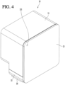
- the entrance refrigerator 10 may include a cabinet 11, an outdoor side door 12, an indoor side door 13, and a housing 15.
- the cabinet 11 has a front opening provided in a portion of the cabinet 11 located at the front (exterior) side of the door or exterior wall, and a rear opening provided in a portion of the cabinet 11 located at the rear (interior) side of the door or interior wall.
- the cabinet 11 may have an approximately hexahedral shape with a front wall and a rear wall interconnected by a plurality of side walls.
- the front opening may be provided in the front wall of the cabinet 11, and the rear opening may be provided in the rear wall of the cabinet 11, although the embodiment is not limited thereto.
- the front opening and the rear opening may be provided on a same side of the cabinet 11 depending on the location where the entrance refrigerator 10 is being installed.
- the outdoor side door 12 may be rotatably coupled to the cabinet 11 so as to selectively open or close the front opening of the cabinet 11.
- the outdoor side door 12 may be opened by the delivery person in order to store goods in the entrance refrigerator 10.
- the outdoor side door 12 may be opened by the user so as to withdraw goods from the entrance refrigerator 10.
- the term "user” is defined as a person who has ordered goods that are stored in the entrance refrigerator 10 by the delivery person, or as a person having authority to release the goods from the entrance refrigerator 10.
- the indoor side door 13 may be rotatably coupled to the cabinet 11 so as to selectively open or close the rear opening of the cabinet 11.
- a display 14 may be provided on the outdoor side door 12.
- the display 14 may display information about an operating state of the entrance refrigerator 10, an internal temperature of the entrance refrigerator 10, and the presence or absence of goods in the entrance refrigerator 10.
- the delivery person who delivers goods may input a password or the like through the display 14 for opening the outdoor side door 12.
- a code scanner for recognizing an encryption code provided in a shipping order or a shipping box may be provided on one side of the outdoor side door 12.
- the indoor side door 13 is used by the user within the house to take out goods stored in the entrance refrigerator 10. That is, the user can open the indoor side door 13 to withdraw the goods from the entrance refrigerator 10 and into the house.
- a guide light 131 may be provided at one side of the indoor side door 13.
- the guide light 131 may be a device for informing a user whether or not goods are currently stored in the entrance refrigerator 10.
- the color of the guide light 131 may be set differently depending on whether goods are stored in the entrance refrigerator 10 or whether the entrance refrigerator 10 is empty. The user may recognize whether there are goods currently being stored even without opening the indoor side door 13.
- the housing 15 is provided at the lower end of the cabinet 11, either integrally as part of the cabinet 11 or as a separate element attached to the cabinet 11.
- a cold air supply device 30 (cold air supplier), to be described later, is accommodated in the housing 15.
- the front surface of the housing 15 comes into close proximity with the rear surface of the front door 1 or the wall when the entrance refrigerator 10 is mounted on the front door 1 or the wall, and contact between a portion of the front surface of the housing 15 and the rear surface of the front door 1 or the wall cancels the moment due to the eccentric load of the entrance refrigerator 10 within the opening of the front door 1 or the wall.
- the entrance refrigerator 10 has a structural characteristic in which a volume of a part exposed indoors is larger than a volume of a part exposed outdoors of the front door 1. Therefore, the center of gravity of the entrance refrigerator 10 is formed at a point eccentric rearwardly of the center of the entrance refrigerator 10. As a result, the moment is generated by the load of the entrance refrigerator 10 and the load of goods stored therein. With such an arrangement, it is possible that the entrance refrigerator 10 could be pulled out of the front door 1 by the moment.
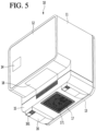
- a pair of guide ducts 16 may be provided at left and right edges of the bottom surface of the housing 15.
- a discharge port 161 is formed at the front end of each guide duct 16 so that indoor room air, which flows into the cold air supply device 30 in the housing 15 and performs a heat dissipation function, may be discharged out of the housing 15.
- a guide plate 18 may be provided on an angled surface of the cabinet 11 formed by the bottom surface of the cabinet 11 and the front surface of the housing 15. The function of the guide plate 18 will be described below with reference to the accompanying drawings.
- An opening for suctioning indoor room air may be formed in the bottom surface of the housing 15, and a suction plate 17 may be mounted at the opening.
- a plurality of through-holes 171 may be formed in the suction plate 17, and indoor room air is introduced into the housing 15 through the plurality of through-holes 171. At least part of the indoor room air introduced into the housing 15 is discharged back out of the housing 15 through the discharge ports 161 of the guide ducts 16.
- a storage compartment 111 in which goods may be stored is provided within the cabinet 11.
- the storage compartment 111 may be considered as a main body of the entrance refrigerator 10 according to the embodiment.
- a tray 19 on which goods are placed may be provided at a lower portion of the storage compartment 111.
- a guide rib 25 may be formed along the rear edge of the cabinet 11.
- the guide rib 25 may protrude a predetermined distance from the rear surface of the cabinet 11 and extend along an edge of the cabinet 11.
- the guide rib 25 is provided to guide some of the air discharged from the housing 15 upwardly to the area surrounding the indoor side door 13 so that condensation is prevented from forming on a gasket 22 surrounding the rear surface of the indoor side door 13.
- the entrance refrigerator 10 may include the cabinet 11, the indoor side door 13, the outdoor side door 12, the housing 15, the guide duct 16, the suction plate 17, and the tray 19.
- the entrance refrigerator 10 may further include a base plate 20 disposed at the bottom portion of the cabinet 11.
- the tray 19 may be disposed above the base plate 20.
- the bottom surface of the tray 19 may be spaced apart upward from the base plate 20.
- the entrance refrigerator 10 further includes a cold air supply device 30 accommodated in the housing 15.
- the cold air supply device 30 may be a device to which a thermoelectric element (Peltier element) is applied, but the cold air supply device 30 is not limited thereto.
- a general cooling cycle may be applied to the cold air supply device 30.
- thermoelectric element When a current is supplied to the thermoelectric element, one surface thereof acts as a heat absorbing surface in which a temperature drops, and the other surface thereof acts as a heat generating surface in which a temperature increases.
- the heat absorbing surface and the heat generating surface are swapped.
- the entrance refrigerator 10 may further include a mount plate 24 mounted on the bottom of the cabinet 11, and a flow guide 23 mounted on the upper surface of the mount plate 24.
- the flow guide 23 may be understood as a device for forming the flow passage of the air inside the storage compartment 111 which forcibly flows by the heat absorption fan 33.
- the base plate 20 may be disposed above the flow guide 23 to minimize a possibility that foreign substances could fall directly onto the flow guide 23.
- An outer gasket 21 is provided on an inner side of the outdoor side door 12 that faces the cabinet 11, and an inner gasket 22 is provided on an inner side of the indoor side door 13 that faces the cabinet 11.
- the outer gasket 21 and the inner gasket 22 prevent cold air within the storage compartment 111 from leaking to the outside of the entrance refrigerator 10.
- the outer gasket 21 may be provided on a portion of the cabinet 11 that faces an inner side of the outdoor side door 12, and the inner gasket 22 may be provided on a portion of the cabinet 11 that faces an inner side of the indoor side door 13.
- the portion of the cabinet 11 may be a contact shoulder 115 to be described later.
- the outer gasket 21 and the inner gasket 22 prevent cold air within the storage compartment 111 from leaking to the outside of the entrance refrigerator 10.
- the mount plate 24 may have a shape in which a rectangular plate is bent a plurality of times.
- the mount plate 24 may include a flow guide seating portion 241, a front flange 244, and a rear flange 245.
- the flow guide 23 is disposed directly above the flow guide seating portion 241, and a space formed between the flow guide 23 and the flow guide seating portion 241 may be defined as a cold air supply flow passage.
- the temperature of the cold air flowing due to the heat absorption fan 33 is lowered while passing through the cold sink 32.
- the cold air is distributed to the left and right sides of the cold sink 32 and flows into the bottom left and bottom right sides of the storage compartment 111 along the cold air supply flow passage.
- a through-hole 242 may be formed in the center of the flow guide seating portion 241, and part of the cold air supply device 30 may pass through the through-hole 242 and be mounted therein.
- the cold sink 32 is disposed in the through-hole 242, such that the cold air passing through the cold sink 32 and the water formed on the cold sink 32 flow to the flow guide seating portion 241. The flow of cold air passing through the cold sink 32 and the flow of condensation formed on the surface of the cold sink 32 will be described in more detail with reference to the accompanying drawings.
- the flow guide seating portion 241 may include a left flow guide seating portion 241a formed at the left side of the through-hole 242 and a right flow guide seating portion 241b formed at the right side of the through-hole 242.
- a drain hole 243 may be formed in either or both of the left flow guide seating portion 241a and the right flow guide seating portion 241b.
- An example in which the drain hole 243, and the drain port and the drain box, which will be described later, are provided only at the left side of the through-hole 242 is described herein, but it is noted that the same may also be provided on the right side of the through-hole 242. However, for convenience of description, an example in which they are formed only at the left side of the through-hole 242 is described below.
- the bottom portion in which the drain hole 243 is formed that is, the left flow guide seating portion 241a in the present embodiment, is formed to be slanted to direct water toward the drain hole 243.
- the left edge and the right edge of the left flow guide seating portion 241a are preferably designed to be higher than the drain hole 243.
- the front end and the rear end of the left flow guide seating portion 241a may be designed to be higher than the drain hole 243.
- the front flange 244 may include a vertical portion 244a extending upward from a front end of the flow guide seating portion 241, and a horizontal portion 244b extending forward from the upper end of the vertical portion 244a.
- the vertical portion 244a does not necessarily need to be perpendicular to the horizontal plane, and the horizontal portion 244b does not necessarily need to be the same plane as the horizontal plane.
- the front flange 244 is sufficient to be bent along contours of a seating shoulder 111d (see Fig. 16 ) formed at the bottom of the cabinet 11.
- the rear flange 245 may also include a vertical portion 245a and a horizontal portion 245b so as to be seated on the seating shoulder 111d.
- the vertical portion 245a of the rear flange 245 does not necessarily need to be perpendicular to the horizontal plane, and the horizontal portion 245b does not necessarily need to be the same plane as the horizontal plane.
- Guide ribs 246 may extend downward from the left edge and the right edge of the through-hole 242, respectively, to assist with holding the cold air supply device 30 in place.
- the cabinet 11 may include a first portion 112 (exterior portion) inserted through the front door 1 or the wall, and a second portion 113 (interior portion) exposed to the inside.
- the lower end of the second portion 113 may extend downward further than the lower end of the first portion 112.
- the front surface of the second portion 113 extending downward from the rear end of the bottom of the first portion 112 may be defined as a door contact surface 114.
- the door contact surface 114 prevents the entrance refrigerator 10 from being separated from the front door 1 or the wall by the moment.
- a contact shoulder 115 may be formed at a point spaced apart rearward from the front end of the cabinet 11 by a predetermined distance.
- the contact shoulder 115 may protrude from the inner circumferential surface of the cabinet 11 by a predetermined height, and may have a rectangular band shape extending along the inner circumferential surface of the cabinet 11.
- a rectangular opening defined along the inner edge of the contact shoulder 115 may define an inlet portion for goods entering or exiting the storage compartment 111.
- a space between the front end of the cabinet 11 and a front surface of the contact shoulder 115 may be defined as an outdoor side door accommodation portion into which the outdoor side door 12 is received.
- the outer gasket 21 is in close contact with the front surface of the contact shoulder 115 to prevent leakage of cold air from the storage compartment 111.
- the longitudinal cross-section of the storage compartment 111 defined at the rear of the contact shoulder 115 may have the same size as the longitudinal cross-section of the inlet portion. That is, the bottom surface of the storage compartment 111 may be coplanar with the upper edge of the contact shoulder 115 extending from the inner circumferential surface of the bottom portion of the cabinet 11.
- the bottom surface of the storage compartment 111 may include the base plate 20.
- left and right side surfaces of the storage compartment 111 may be coplanar with the inner edges of the contact shoulder 115 extending from the left inner circumferential surface and the right inner circumferential surface of the cabinet 11, respectively.
- the ceiling surface of the storage compartment 111 may be coplanar with the lower edge of the contact shoulder 115 extending from the inner circumferential surface of the upper end of the cabinet 11.
- the inner circumferential surface of the storage compartment 111 is coplanar with the inner edges of the contact shoulder 115.
- the present disclosure is not limited to the above configuration.
- the bottom surface of the storage compartment 111 may be coplanar with the bottom surface of the outdoor side door accommodation portion.
- the contact shoulder 115 may be described as including a lower shoulder 115a, a left shoulder 115b, a right shoulder (see Figure 6 ), and an upper shoulder 115c, and the bottom surface (floor) of the storage compartment 111 may be designed to be lower than the upper edge of the lower shoulder 115a.
- left and right side surfaces of the storage compartment 111 may be designed to be wider than the inner edges of the left shoulder 115b and the right shoulder.
- the upper surface (ceiling) of the storage compartment 111 may be designed to be higher than the lower edge of the upper shoulder 115c.
- the width and height of the storage compartment 111 may be formed to be larger than the width and height of the inlet portion.
- a slot 116 may be formed at the bottom of the cabinet 11 corresponding to the bottom of the outdoor side door accommodation portion.
- the point where the slot 116 is formed may be described as a point spaced a predetermined distance rearward from the front end of the cabinet 11, or a point spaced a predetermined distance forward from the front surface of the contact shoulder 115.
- the slot 116 may be formed at a position closer to the contact shoulder 115 than to the front end of the cabinet 11. As the air that has a relatively high temperature and is discharged from the housing 15 rises, the air may be introduced into the outdoor side door accommodation portion of the cabinet 11 through the slot 116.
- the air flowing through the slot 116 flows along the edge of the outer gasket 21 to evaporate any condensation that may form on the outer gasket 21.
- an inwardly stepped portion 119 may be formed in the bottom surface of the cabinet 11 corresponding to the first portion 112 and in the front surface of the cabinet 11 corresponding to the second portion 113.
- the stepped portion 119 is enclosed by the guide plate 18, and an air flow passage 119a is formed between the guide plate 18 and the stepped portion 119.
- the lower end of the air flow passage 119a communicates with the inside of the housing 15, and the upper end of the air flow passage 119a is connected to the slot 116.
- the relatively high-temperature air discharged from the housing 15 moves along the air flow passage 119a and flows into the slot 116.
- the air flowing through the slot 116 flows along the edge of the outer gasket 21 to evaporate any condensation that may form on the outer gasket 21.
- a mount plate seating portion 117 may be formed at a predetermined depth on the inner bottom surface of the cabinet 11, particularly on the bottom surface of the cabinet 11 corresponding to the second portion 113.
- the seating shoulder 111d may have a stepped shape at each of the front surface and the rear surface of the mount plate seating portion 117.
- the seating shoulder 111d may include a front seating shoulder and a rear seating shoulder.
- the front seating shoulder may have a stepped shape extending from the bottom surface of the mount plate seating portion 117 by a predetermined height and protruding forward from the front surface of the mount plate seating portion 117.
- the rear seating shoulder may have a stepped shape extending from the bottom surface of the mount plate seating portion 117 by a predetermined height and protruding rearward from the rear surface of the mount plate seating portion 117.
- a through-hole 118 is formed on the bottom surface of the mount plate seating portion 117.
- the bottom surface of the mount plate seating portion 117 includes a left drain floor 111e formed at the left side of the through-hole 118, and a right drain floor 111g formed at the right side of the through-hole 118.
- the mount plate 24 may be seated on the bottom of the mount plate seating portion 117.
- the bottom of the mount plate seating portion 117 is designed to be slanted in the same shape as the bottom of the mount plate 24, such that the bottom of the mount plate 24 is in close contact with the bottom of the mount plate seating portion 117.
- the left flow guide seating portion 241a of the mount plate 24 may be in close contact with the left drain floor 111e, and the right flow guide seating portion 241b may be in close contact with the right drain floor 111g.
- a drain hole 111f may be formed in the bottom surface of the mount plate seating portion 117, and the center of the drain hole 111f may be placed on the same vertical line as the center of the drain hole 243 formed in the mount plate 24.
- the diameters of the two drain holes 111f and 243 may be formed to be the same.
- the through-hole 242 of the mount plate 24 may be formed to have the same size as the through-hole 118 of the mount plate seating portion 117, and the centers of the through-hole 242 and the through-hole 118 may be placed on the same vertical line.
- the bottom of the storage compartment 111 may include a front floor 111a, a left side floor 111b, and a right side floor 111c (see Fig. 15 ).
- the front floor 111a is formed in front of the mount plate seating portion 117, and the left side floor 111b and the right side floor 111c are formed on the left and right sides, respectively, of the mount plate seating portion 117.
- the bottom of the storage compartment 111 except for the mount plate seating portion 117 may be defined as a main floor, and the left drain floor 111e and the right drain floor 111g may be defined as a sub floor.
- the front floor 111a may be formed to be slanted to be lowered toward the mount plate seating portion 117 from the front end, such that water falling on the front floor 111a flows down toward the mount plate seating portion 117.
- left side floor 111b and the right side floor 111c may also be designed to be slanted to be lowered toward the mount plate seating portion 117, such that water falling on the left side floor 111b and the right side floor 111c flows down toward the mount plate seating portion 117.
- the cold air supply device 30 passes through the through-holes 118 and 242 such that the upper portion of the cold air supply device 30 is partially exposed to the storage compartment and the lower portion of the cold air supply device 30 is partially exposed to the inside of the housing 15.
- a drain port 111h may protrude downward from the outer bottom surface of the cabinet 11 by a predetermined length.
- An upper opening of the drain port 111h communicates with the drain hole 111f formed in the bottom of the mount plate seating portion 117.
- a drain box 50 is mounted on the outer bottom surface of the cabinet 11 to store water discharged from the drain port 111h.
- one side of the side surface of the drain port 111h may be opened, and an actuator 60 which selectively opens or closes the opened portion may be disposed below the cabinet 11.
- the actuator 60 may be accommodated inside the housing 15 and does not necessarily need to be attached to the bottom of the cabinet 11.
- the actuator 60 and the opening portion of the drain port 111h opened or closed by the actuator 60 will be described below in more detail with reference to the drawings.
- the drain box 50 may be formed in a hexahedral shape in which portions of the upper surface and the side surfaces thereof are opened, but the present disclosure is not necessarily limited thereto.
- the drain box 50 may include a bottom portion 51, a front portion 52, a rear portion 53, a left side portion 54, a right side portion 55, and an upper portion that is opened.
- a short side of the bottom portion 51 may be defined as a width, and a long side of the bottom portion 51 may be defined as a length.
- the front portion 52 extends upward from a front end of the bottom portion 51 by a predetermined height, and a fastening rib 521 protrudes from the outer peripheral surface of the upper end thereof.
- a fastening hole 522 is formed in the fastening rib 521.
- the rear portion 53 extends upward from a rear end of the bottom portion 51 by a predetermined height, and a fastening rib 531 protrudes from the outer peripheral surface of the upper end thereof.
- a fastening hole 532 is formed in the fastening rib 531.
- the upper ends of the front portion 52 and the rear portion 53 may be on the same plane and may come in close contact with the bottom surface of the cabinet 11.
- the left side portion 54 may extend upward from the left end of the bottom portion 51 by the same height as the front portion 52.
- a left recessed portion 541 may be formed in the left side portion 54 to be recessed downwardly by a predetermined depth.
- the right side portion 55 may extend upward from the right end of the bottom portion 51 by the same height as the left side portion 54.
- a right recessed portion 551 may be formed in the right side portion 55 to be the same size as the left recessed portion 541.
- the left recessed portion 541 and the right recessed portion 551 may be understood as portions of a flow passage of air flowing toward the side end of the housing 15 due to the heat dissipation fan 36. That is, the left recessed portion 541 and the right recessed portion 551 may be understood as being provided to prevent the flow of air forcedly flowing due to the heat dissipation fan 36 from being disturbed by the drain box 50.
- the air passing through the left recessed portion 541 and the right recessed portion 551 is in a state in which the temperature is raised due to exchanging heat with the heat sink 34. Therefore, the high-temperature air flowing across the drain box 50 is discharged to the outside of the housing 15 in a state in which the humidity is increased by evaporating the condensed water stored in the drain box 50.
- a port receiver 56 may protrude upward from the bottom portion 51 by a predetermined height.
- a recessed portion 561 recessed from the upper end of the port receiver 56 by a predetermined depth D may be formed in the port receiver 56.
- the end portion of the drain port 111h extending from the bottom surface of the cabinet 11 is accommodated in the recessed portion 561. Therefore, the condensed water discharged from the drain port 111h falls into the recessed portion 561, and the condensed water that overflows from the recessed portion 561 is collected in the main portion of the drain box 50 defined by the bottom portion 51, the front portion 52, the rear portion 53, the left side portion 54, and the right side portion 55.
- the end portion of the drain port 111h is kept submerged in the condensed water filled in the recessed portion 561, the occurrence of air flowing from the housing 15 into the storage compartment 111 through the drain port 111h may be prevented.
- a device for draining the condensed water collected in the drain box 50 may be further provided.
- a drain hose may be provided at one side of the bottom portion 51, and the drain hose may extend outward from the housing 15.
- a drain pump may be attached to one side of the drain box 50, and a drain hose may extend from the drain pump to the outside of the housing 15.
- an opening/closing port may be formed on the rear surface of the housing 15, that is, the opposite side of the surface in close contact with the front door 1, and the drain box 50 may be slidably withdrawn from the housing through the opening/closing port.
- the lower end of the drain port 111h is spaced apart from the upper end of the port receiver 56.
- the drain box 50 may be mounted on the bottom surface of the cabinet 11 so as to be slidably movable in the front-to-rear direction of the cabinet 11, and a protective cover may be rotatably mounted on the opening/closing port.
- an accommodation box for accommodating the drain box 50 may be provided on the bottom surface of the cabinet 11 exposed to the internal space of the housing 15, and a drawer structure in which the drain box 50 is slidably inserted into the accommodation box may be provided.
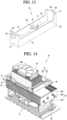
- the cold air supply device 30 illustrated in Fig. 14 is a cold air supply device 30 that is cut by a vertical plane extending in the horizontal direction such that a front portion thereof is removed.
- the cold air supply device 30 may include a thermoelectric element 31, a cold sink 32 attached to the heat absorbing surface of the thermoelectric element 31, a heat absorption fan 33 disposed in front of (or above) the cold sink 32, a heat sink 34 attached to the heat generating surface of the thermoelectric element 31, a heat dissipation fan 36 disposed behind (or below) the heat sink 34, and an insulation material 35 for preventing heat transfer between the cold sink 32 and the heat sink 34.
- the insulation material 35 is provided to surround the side surface of the thermoelectric element 31.
- the cold sink 32 is in contact with the front surface of the insulation material 35, and the heat sink 34 is in contact with the rear surface of the insulation material 35.
- the cold sink 32 and the heat sink 34 may include a thermal conductor directly attached to the heat absorbing surface or the heat generating surface, respectively, of the thermoelectric element 31, and a plurality of heat exchange fins extending from the surface of the thermal conductor.
- the heat absorption fan 33 is disposed to face the inside of the cabinet 11, and the heat dissipation fan 36 is disposed directly above the suction plate 17.
- the cold sink 32 includes a sink body 321 in direct contact with the heat absorbing surface of the thermoelectric element 31, and a plurality of heat exchange fins 322 arranged on the upper surface of the sink body 321.
- the sink body 321 may include a first portion in direct contact with the heat absorbing surface of the thermoelectric element 31, and a second portion formed on the upper surface of the first portion and having an area larger than that of the first portion.
- the heat sink 34 includes a sink body 341 in direct contact with the heat generating surface of the thermoelectric element 31, and a plurality of heat exchanger fins 342 arranged on the bottom surface of the sink body 341 and connected with the sink body 341 by a plurality of heat pipes 343.
- the sink body 341 may include a first portion in direct contact with the heat generating surface of the thermoelectric element 31, and a second portion formed on the bottom surface of the first portion and having an area larger than that of the first portion.
- the insulation material 35 may be interposed between the second portion of the cold sink 32 and the second portion of the heat sink 34.
- the insulation material 35 may have a rectangular band shape.
- the components of the cold air supply device 30 except for the heat absorption fan 33 and the heat dissipation fan 36 may be defined as a thermoelectric module.
- the heat absorption fan 33 may be fixedly coupled to the fan housing of the flow guide 23, and the heat dissipation fan 36 may be fixedly coupled to the suction plate 17 or the lower side of the thermoelectric module by one or more fastening screws.
- a fastening bracket 38 may be coupled to the outer circumferential surface of the insulation material 35.
- the fastening bracket 38 may be understood as a mounting member that allows the thermoelectric module to be fixedly mounted on the bottom surface of the cabinet 11.
- a sealing member 37 may surround the upper surface of the fastening bracket 38.
- the sealing member 37 is in close contact with the edge of the through-hole 118 formed in the bottom of the cabinet 11. Therefore, the sealing member 37 prevents the air inside the storage compartment 111 from leaking to the internal space of the housing 15.
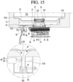
- Fig. 15 is a partial longitudinal cross-sectional view of the entrance refrigerator 10, taken along line 15-15 of Fig. 10
- Fig. 16 is a partial longitudinal cross-sectional view of the entrance refrigerator 10, taken along line 16-16 of Fig. 10 .
- a drain structure that collects water, falling on the bottom of the storage compartment 111 or water formed on the surface of the cold sink 32 of the cold air supply device 30, in one place, and discharges the water to the outside of the storage compartment 111.
- the bottom surface of the storage compartment 111 may be slanted to one side.
- the inner bottom surface of the cabinet 11 forming the bottom of the storage compartment 111 may include the front floor 111a, the left side floor 111b, and the right side floor 111c.
- the surface defined as the seating shoulder 111d may also be formed on the rear side of the bottom surface of the storage compartment 111.
- the bottom surface of the storage compartment 111 may be designed to be slanted to be lowered toward the mount plate seating portion 117. According to this structure, all the water falling on the bottom of the storage compartment 111 flows down along the edge of the mount plate seating portion 117.
- the water flowing along the edge of the mount plate seating portion 117 flows to the upper surface of the mount plate 24 disposed on the mount plate seating portion 117.
- the drain hole 243 (see Fig. 9 ) is formed in the flow guide seating portion 241 of the mount plate 24, and the flow guide seating portion 241 is formed to be slanted downward toward the drain hole 243. Thus, the water flowing onto the mount plate 24 is discharged through the drain hole 243.
- the water falling on the right flow guide seating portion 241b formed on the right side of the through-hole 242 of the mount plate 24 flows toward the left flow guide seating portion 241a along the upper surface of the sink body 321 of the cold sink 32.
- the upper surface of the left end of the sink body 321 and the upper surface of the right end of the sink body 321 may be designed to form the same surface as the right edge of the left flow guide seating portion 241a and the left edge of the right flow guide seating portion 241b, respectively.
- the drain hole 243 may be formed in the right flow guide seating portion 241b. That is, the left flow guide seating portion 241a and the right flow guide seating portion 241b may be symmetrical with respect to the vertical plane that divides the through-hole 242 from left and right.
- thermoelectric module may be mounted to be slanted with respect to the cabinet 11, as shown in Fig. 15 , such that the water formed on the surface of the cold sink 32 flows toward the drain hole 243 of the mount plate 24 along the upper surface of the sink body 321 of the cold sink 32.
- At least the left edge of the sink body 321 of the cold sink 32 is coupled below the right edge, such that the water flowing down on the upper surface of the sink body 321 flows toward the drain hole 243.
- the upper surface of the sink body 321 and the upper surface of the right flow guide seating portion 241b of the mount plate 24 form a single slanted surface, such that the water falling on the right flow guide seating portion 241b flows along the upper surface of the sink body 321 and flows to the drain hole 243.
- the thermoelectric module may be coupled to the cabinet such that the right edge of the sink body 321 is lower than the left edge of the right flow guide seating portion 241b, and the right edge of the left flow guide seating portion 241a is lower than the left edge of the sink body 321.
- the bottom surface of the left flow guide seating portion 241a of the mount plate 24 may be in close contact with the upper surface of the left drain floor 111e.
- the bottom surface of the right flow guide seating portion 241b of the mount plate 24 may be in close contact with the upper surface of the right drain floor 111g.
- the upper left end of the upper surface of the cold sink 32 is illustrated as being higher than the upper left end of the cold sink 32, the upper left end may be designed to be higher than the right end of the upper surface, if the drain port 111h is provided in the right drain floor 111g.
- the drain hole 111f is formed in the lower drain floor at the bottom surface of the mount plate seating portion 117.
- the drain floor adjacent to the higher side end of the cold sink 32 may be defined as a first drain floor, and the drain floor adjacent to the lower side end may be defined as a second drain floor.
- the heat absorption fan 33 may be horizontally coupled to the fan housing 232 of the flow guide 23 to be oriented horizontally and parallel to a ground surface (i.e. level).
- the heat dissipation fan 36 is illustrated as being slantingly coupled to the lower side of the thermoelectric module at an angle non-parallel with respect to the ground surface (i.e. non-level), but the present disclosure is not limited thereto.
- the heat dissipation fan 36 may be horizontally coupled to the lower side of the thermoelectric module to be oriented horizontally parallel to the ground surface (i.e. level) like the heat absorption fan 33.
- the drain port 111h is also used as a passage for supplying outside air to the storage compartment 111.
- an air hole 111i is formed in the drain port 111h.
- the air hole 111i may be formed at a point between the upper end and the lower end of the drain port 111h, and the air hole 111i is selectively opened or closed by the actuator 60.
- the actuator 60 may include a driver 61 and a plunger 62 connected to the driver 61 to move forward or backward from the driver 61 toward the air hole 111i.
- the driver 61 may be a motor and a gear assembly which rotates by receiving rotational force of the motor, and a rack gear may be formed on the outer circumferential surface of the plunger 62 to engage with the gear assembly.
- the end portion of the plunger 62 may be provided with a conical head portion such that the air hole 111i is closed.
- the conical head portion acts as a stopper to plug the air hole 111i.
- the driver 61 may be a solenoid which generates electromagnetic force when a current is applied thereto, such that the plunger 62 moves forward or backward.
- the driver 61 may include a spring to restore the plunger 62 to its original position when the current is no longer applied to the driver 61.
- a carbon dioxide sensor 41b which detects a concentration of carbon dioxide may be mounted inside the storage compartment 111.
- a controller 41a of the entrance refrigerator 10 may determine that a living organism is present in the storage compartment 111. When the living organism is detected, the controller 41a may allow power to be supplied to the driver 61.
- the plunger 62 keeps the air hole 111i closed to prevent outside air from flowing into the storage compartment 111.
- the outside air introduced through the air hole 111i is air inside the housing 15, that is, indoor air having a high temperature by heat exchange with the heat sink 34. Therefore, in order to maintain the internal temperature of the storage compartment 111 at a set temperature, outside air is not introduced through the air hole 111i under normal conditions.
- the driver 61 may be driven such that the plunger 62 moves backward to open the air hole 111i.
- a motion sensor 41c which detects a movement of an object inside the storage compartment 111 is provided inside the storage compartment 111.
- the controller 41a supplies power to the actuator 60 such that the air hole 111i is opened.
- the motion sensor 41c may include a PIR sensor, but the present disclosure is not limited thereto.
- Fig. 17 is a partial longitudinal cross-sectional view of the entrance refrigerator, taken along line 15-15 of Fig. 10 , showing an air hole opening/closing structure according to an embodiment.
- the air hole opening/closing structure may include an actuator 60 which is the same as that described with reference to Fig. 15 , and a drain cover 70 rotatably coupled to the lower end of the drain port 111h.
- the actuator 60 may be the same actuator as that described with reference to Fig. 15 .
- the actuator 60 includes a driver 61 and a plunger 62. When power is supplied to the driver 61, the plunger 62 moves in the vertical direction.
- the drain cover 70 coupled to the lower end of the drain port 111h may include a shielding plate 72 which shields a condensed water discharge port formed in the lower end of the drain port 111h, and a hinge shaft 71 formed at one end of the shielding plate 72.
- a shaft connection portion 111j protrudes from the outer circumferential surface of the end portion of the drain port 111h.
- the hinge shaft 71 may be inserted into the shaft connection portion 111j after passing through one end of the shielding plate 72.
- the end portion of the shielding plate 72 is bent, and the hinge shaft 71 passes through the bent end portion of the shielding plate 72. That is, the shielding plate 72 may be bent in an "L" shape.
- the shaft connection portion 111j may be bent in a "b" shape, and the shielding plate 72 may be formed of a flat disk or a polygonal plate.
- a torsion spring 73 may be wound around the hinge shaft 71. When no external force is applied to the shielding plate 72, the shielding plate 72 may be maintained in close contact with the end portion of the drain port 111h by the elastic force of the torsion spring 73.
- the drain port 111h is opened only at the time when the condensed water is discharged to the drain box 50. While the drain port 111h is opened, outside air is barely introduced into the storage compartment 111 as the condensed water is discharged through the drain port 111h. Therefore, a structure such as the port receiver 56 may not be required.
- the actuator 60 may be disposed on the side of the drain port 111h to press the shielding plate 72 such that the drain port 111h is forcibly opened.
- the controller 41a supplies power to the driver 61.
- the plunger 62 moves downward to press the shielding plate 72 downward, and the shielding plate 72 rotates downward to open the condensed water discharge port of the drain port 111h.
- the elastic restoring force is accumulated in the torsion spring 73. Therefore, when the supply of power is cut off or the reverse voltage is supplied to the driver 61, the plunger 62 moves upward, and the shielding plate 72 shields the condensed water discharge port of the drain port 111h by the restoring force of the torsion spring 73.
- the companion animal may be placed in an environment higher than the companion animal's own body temperature and thus die.
- the controller 41a may control the driving of the actuator 60 and control the driving of the cold air supply device 30.
- the controller 41a may control the amount of current supplied to the thermoelectric element 31 or the flow direction of current such that the internal temperature of the storage compartment 111 is maintained at a temperature most suitable for the survival of the companion animal.
- the controller 41a may adjust the amount of current supplied to the cold air supply device 30 and the flow direction of current such that the internal temperature of the storage compartment is maintained within a temperature range of 20°C to 25°C, which is most suitable for the survival of the companion animal.
- the controller 41a may control the guide light 131 to warn a user that a living organism is currently located in the entrance refrigerator 10.
Landscapes
- Engineering & Computer Science (AREA)
- Physics & Mathematics (AREA)
- Mechanical Engineering (AREA)
- Thermal Sciences (AREA)
- General Engineering & Computer Science (AREA)
- Chemical & Material Sciences (AREA)
- Combustion & Propulsion (AREA)
- Cold Air Circulating Systems And Constructional Details In Refrigerators (AREA)
- Devices That Are Associated With Refrigeration Equipment (AREA)
Claims (15)
- Réfrigérateur, comprenant :une carrosserie (11) installée de manière à traverser une porte ou un mur ou à y être encastrée, définissant un compartiment de stockage (111) pour le rangement d'articles ;un boîtier (15) raccordé à, ou formé d'un seul tenant avec une partie inférieure de la carrosserie (11) ;une porte latérale extérieure (12) prévue pour ouvrir ou fermer un côté avant du compartiment de stockage (111) et exposée à l'extérieur d'un espace, la porte ou le mur étant une limite dudit espace ;une porte latérale intérieure (13) prévue pour ouvrir ou fermer un côté arrière du compartiment de stockage (111) et exposée à l'intérieur de l'espace ;un dispositif de refoulement d'air froid, dont au moins une partie est disposée dans le boîtier (15), prévu pour refroidir l'air dans le compartiment de stockage (111) ; etun contrôleur prévu pour commander le fonctionnement du dispositif de refoulement d'air froid,caractérisé en ce que :la carrosserie (11) comporte un trou de drainage (111t) au fond du compartiment de stockage (111) ;le réfrigérateur comprend en outreun port de drainage (111h) s'étendant depuis une surface inférieure de la carrosserie (11) et communiquant avec le trou de drainage (111f) ; etun actionneur (60) prévu pour ouvrir ou fermer sélectivement une ouverture formée dans le port de drainage (111h) ; etle contrôleur est en outre prévu pour commander le fonctionnement de l'actionneur (60) afin d'empêcher la survenue d'une pénurie d'oxygène dans un compartiment de stockage (111) si un animal de compagnie est piégé dans ledit compartiment de stockage (111).
- Réfrigérateur selon la revendication 1, où l'actionneur (60) comprend :un piston (62) prévu pour effectuer un mouvement de va-et-vient linéaire ; etun entraînement (61) prévu pour fournir une force motrice permettant le mouvement de va-et-vient linéaire du piston (62).
- Réfrigérateur selon la revendication 2, où l'entraînement (61) comprend un solénoïde.
- Réfrigérateur selon la revendication 2, où l'entraînement comprend :un moteur ; etun ensemble d'engrenages prévu pour transmettre la force de rotation du moteur au piston.
- Réfrigérateur selon l'une des revendications 2 à 4, où l'ouverture est un trou d'air (111i) formé sur un point situé entre une extrémité supérieure et une extrémité inférieure du port de drainage (111h), et
où le trou d'air (111i) est sélectivement ouvert ou fermé par une partie terminale du piston (62) effectuant le mouvement de va-et-vient linéaire sensiblement dans la direction horizontale. - Réfrigérateur selon l'une des revendications 2 à 5, comprenant en outre une boîte de drainage (50) située sous la carrosserie (11) pour stocker l'eau de condensation évacuée par le port de drainage (111h),
où la boîte de drainage (50) comprend un récepteur de port (56) faisant saillie sur le fond de la boîte de drainage (50). - Réfrigérateur selon la revendication 6, où une partie en renfoncement (561) que l'eau de condensation peut remplir est formée à une extrémité supérieure du récepteur de port (56) à une profondeur prédéterminée, et où l'extrémité inférieure du port de drainage (111h) est reçue dans la partie en renfoncement (561).
- Réfrigérateur selon l'une des revendications 2 à 4, où l'ouverture est un orifice d'évacuation d'eau de condensation formé à une extrémité inférieure du port de drainage (111h), et
où le réfrigérateur comprend en outre un couvercle de drainage (70) prévu de manière pivotante à l'extrémité inférieure du port de drainage (111h) pour ouvrir ou fermer sélectivement l'orifice d'évacuation d'eau de condensation. - Réfrigérateur selon la revendication 8, où le couvercle de drainage (70) comprend :une plaque de protection (72) prévue pour protéger l'orifice d'évacuation d'eau de condensation ; etun axe d'articulation (71) prévu pour raccorder de manière pivotante une partie d'extrémité de la plaque de protection (72) à une surface circonférentielle extérieure du port de drainage (111h).
- Réfrigérateur selon la revendication 9, où la plaque de protection (72) est pivotée autour de l'axe d'articulation (71) par une partie d'extrémité du piston s'étendant vers le bas, et où
l'orifice d'évacuation d'eau de condensation est ouvert lorsque la plaque de protection (72) est séparée de l'extrémité inférieure du port de drainage (111h). - Réfrigérateur selon la revendication 10, comprenant en outre un ressort de torsion enroulé autour de l'axe d'articulation (71),
où, lorsque le piston (62) se déplace vers le haut, la plaque de protection (72) est pivotée par la force de rappel élastique du ressort de torsion pour protéger l'orifice d'évacuation d'eau de condensation. - Réfrigérateur selon l'une des revendications 8 à 11, comprenant en outre une boîte de drainage (50) située sous la carrosserie (11) pour stocker l'eau de condensation évacuée par le port de drainage (111h),
où l'actionneur (60) et le port de drainage (111h) sont logés dans la boîte de drainage. - Réfrigérateur selon l'une des revendications 1 à 12, comprenant en outre au moins un capteur de mouvement monté à l'intérieur du compartiment de stockage (111) et un capteur de dioxyde de carbone monté à l'intérieur du compartiment de stockage (111).
- Réfrigérateur selon la revendication 13, où le contrôleur est prévu pour :recevoir un ou plusieurs signaux du capteur de mouvement et/ou du capteur de dioxyde de carbone ; etcommander le fonctionnement de l'actionneur lorsqu'il est déterminé qu'un mouvement d'un organisme vivant est détecté, et/ou qu'une concentration de dioxyde de carbone détectée par le capteur de dioxyde de carbone dépasse une valeur définie.
- Réfrigérateur selon l'une des revendications 1 à 14, où le dispositif de refoulement d'air froid comprend :un module thermoélectrique relié à un trou de passage (118) sur le fond du compartiment de stockage ;un ventilateur d'absorption de chaleur (33) disposé sur ou au-dessus d'un côté du module thermoélectrique pour amener l'air dans le compartiment de stockage (111) à entrer en contact forcé avec le module thermoélectrique ; et un ventilateur de dissipation de chaleur (36) disposé sur ou au-dessous d'un autre côté du module thermoélectrique pour amener l'air dans le boîtier (15) à entrer en contact forcé avec le module thermoélectrique.
Applications Claiming Priority (2)
| Application Number | Priority Date | Filing Date | Title |
|---|---|---|---|
| KR1020190021867A KR102766351B1 (ko) | 2019-02-25 | 2019-02-25 | 현관용 냉장고 |
| KR1020190089221A KR102758303B1 (ko) | 2019-07-23 | 2019-07-23 | 현관용 냉장고 |
Publications (2)
| Publication Number | Publication Date |
|---|---|
| EP3699521A1 EP3699521A1 (fr) | 2020-08-26 |
| EP3699521B1 true EP3699521B1 (fr) | 2023-09-06 |
Family
ID=69726457
Family Applications (1)
| Application Number | Title | Priority Date | Filing Date |
|---|---|---|---|
| EP20158916.5A Active EP3699521B1 (fr) | 2019-02-25 | 2020-02-24 | Réfrigérateur d'entrée |
Country Status (3)
| Country | Link |
|---|---|
| US (1) | US11448456B2 (fr) |
| EP (1) | EP3699521B1 (fr) |
| CN (1) | CN111609652B (fr) |
Families Citing this family (3)
| Publication number | Priority date | Publication date | Assignee | Title |
|---|---|---|---|---|
| KR102996320B1 (ko) * | 2020-07-06 | 2026-07-27 | 엘지전자 주식회사 | 냉장고 |
| US20220205707A1 (en) * | 2020-12-24 | 2022-06-30 | Eric Clifton Roberts | Climate Control Lids |
| US11928642B2 (en) * | 2021-11-17 | 2024-03-12 | Daniel Ruocco | Delivery lockbox assembly |
Family Cites Families (53)
| Publication number | Priority date | Publication date | Assignee | Title |
|---|---|---|---|---|
| US3078682A (en) | 1961-05-29 | 1963-02-26 | Gen Motors Corp | Thermoelectric refrigerating apparatus |
| US3177678A (en) | 1961-09-26 | 1965-04-13 | Westinghouse Electric Corp | Refrigerating apparatus |
| FR1347414A (fr) | 1963-01-29 | 1963-12-27 | Borg Warner | Réfrigérateur thermo-électrique |
| US4738113A (en) | 1985-10-18 | 1988-04-19 | The Cola-Cola Company | Combination cooler and freezer for refrigerating containers and food in outer space |
| US4726193C2 (en) * | 1987-02-13 | 2001-03-27 | Marlow Ind Inc | Temperature controlled picnic box |
| JPH05149675A (ja) | 1991-11-27 | 1993-06-15 | Matsushita Refrig Co Ltd | 冷蔵庫 |
| US5315830B1 (en) * | 1993-04-14 | 1998-04-07 | Marlow Ind Inc | Modular thermoelectric assembly |
| CN2165389Y (zh) | 1993-10-06 | 1994-05-18 | 井侠 | 悬挂式小冰箱 |
| US5774053A (en) * | 1996-05-02 | 1998-06-30 | Porter; David | Storage device for the delivery and pickup of goods |
| TW499559B (en) | 1997-01-31 | 2002-08-21 | Gac Corp | Cold storage apparatus |
| JPH10267501A (ja) | 1997-03-28 | 1998-10-09 | Sanyo Electric Co Ltd | 業務用冷蔵庫 |
| JPH1194423A (ja) | 1997-09-19 | 1999-04-09 | Kazumi Yamamoto | 冷水発生ポット |
| DE19909794A1 (de) * | 1998-11-25 | 2000-09-07 | Bayerische Motoren Werke Ag | Vorrichtung für einen abschließbaren Raum eines Fahrzeugs |
| US20050122682A1 (en) | 2000-12-08 | 2005-06-09 | Robert Streit | Electronics arrangement |
| US6715299B2 (en) | 2001-10-19 | 2004-04-06 | Samsung Electronics Co., Ltd. | Refrigerator for cosmetics and method of controlling the same |
| DE10237132A1 (de) * | 2002-08-13 | 2004-02-26 | BSH Bosch und Siemens Hausgeräte GmbH | Haushaltsgerät mit biometrischer Personenidentifikationseinrichtung |
| US7101341B2 (en) | 2003-04-15 | 2006-09-05 | Ross Tsukashima | Respiratory monitoring, diagnostic and therapeutic system |
| CA2461635A1 (fr) | 2004-03-22 | 2005-09-22 | Marc Bedard | Presentoir frigorifique |
| US7451603B2 (en) * | 2004-03-22 | 2008-11-18 | General Mills, Inc. | Portable cooled merchandizing unit |
| US7934384B2 (en) | 2004-10-22 | 2011-05-03 | General Mills, Inc. | Portable cooled merchandizing unit with customer enticement features |
| WO2006087690A2 (fr) | 2005-02-21 | 2006-08-24 | Arcelik Anonim Sirketi | Dispositif de refroidissement |
| US7308796B1 (en) | 2005-06-03 | 2007-12-18 | Eager Jacob P | Fruit refrigerator |
| CN100549587C (zh) | 2006-12-26 | 2009-10-14 | 财团法人工业技术研究院 | 除雾装置 |
| CN201277783Y (zh) * | 2008-08-25 | 2009-07-22 | 河南新飞电器有限公司 | 冰箱排水管 |
| KR20110033394A (ko) * | 2009-09-25 | 2011-03-31 | 조영택 | 현관문 및 대문에 부착되는 냉장고 |
| WO2011107884A2 (fr) * | 2010-03-05 | 2011-09-09 | Electrolux Home Products Corporation N.V. | Réfrigérateur ou congélateur comprenant un appareil de décongélation |
| CN102914119B (zh) | 2011-07-31 | 2016-08-10 | 博西华家用电器有限公司 | 制冷器具 |
| CN102589236B (zh) * | 2012-02-22 | 2014-08-13 | 合肥美的电冰箱有限公司 | 冰箱及其排水管组件 |
| CN102927748B (zh) * | 2012-11-26 | 2015-05-13 | 合肥美的电冰箱有限公司 | 用于冷柜的排水管组件及具有其的冷柜 |
| CN203534032U (zh) * | 2013-08-02 | 2014-04-09 | 青岛海尔特种电冰箱有限公司 | 用于冰箱的排水管和冰箱 |
| EP2980511A1 (fr) | 2014-08-01 | 2016-02-03 | Werner W. Lorke | Appareil de refroidissement, module de refroidissement et module de nervures de refroidissement et leur utilisation |
| CN105389944A (zh) | 2015-12-03 | 2016-03-09 | 长春工业大学 | 车内滞留儿童预警及自动救助系统 |
| KR20170087705A (ko) | 2016-01-21 | 2017-07-31 | 삼성전자주식회사 | 보관장치 및 그 제어방법 |
| US9750355B1 (en) | 2016-03-02 | 2017-09-05 | Pepsico, Inc. | Refrigerated merchandise display system |
| JP6751909B2 (ja) * | 2016-04-25 | 2020-09-09 | パナソニックIpマネジメント株式会社 | 冷蔵宅配ボックス、およびこれに用いる宅配ボックス |
| KR102632586B1 (ko) | 2016-09-29 | 2024-02-02 | 엘지전자 주식회사 | 냉장고 |
| KR102632585B1 (ko) | 2016-09-29 | 2024-02-02 | 엘지전자 주식회사 | 냉장고 |
| CN206362072U (zh) | 2016-11-30 | 2017-07-28 | 合肥晶弘三菱电机家电技术开发有限公司 | 一种冰箱用接水盘及冰箱 |
| CN206257869U (zh) * | 2016-12-14 | 2017-06-16 | 海信(山东)冰箱有限公司 | 一种冷藏装置及其排水组件 |
| EP3348933B1 (fr) | 2017-01-04 | 2022-03-30 | LG Electronics Inc. | Réfrigérateur |
| MY201770A (en) * | 2017-01-10 | 2024-03-16 | Mitsubishi Electric Corp | Refrigerator |
| JP6874828B2 (ja) | 2017-03-31 | 2021-05-19 | ダイキン工業株式会社 | 硬化性組成物、その製造方法、及びそれを用いた物品 |
| KR102311397B1 (ko) | 2017-04-03 | 2021-10-13 | 엘지전자 주식회사 | 냉장고 |
| CN107084583B (zh) * | 2017-04-25 | 2024-03-26 | 青岛海尔特种电冰柜有限公司 | 制冷电器 |
| CN108800656B (zh) | 2017-04-28 | 2020-09-08 | 青岛海尔智能技术研发有限公司 | 半导体制冷模组及制冷设备 |
| CN207006712U (zh) * | 2017-06-26 | 2018-02-13 | 合肥华凌股份有限公司 | 用于制冷器具的安全防护组件、安全防护系统及制冷器具 |
| US10824175B2 (en) | 2017-07-28 | 2020-11-03 | Stmicroelectronics, Inc. | Air flow measurement using pressure sensors |
| KR102342315B1 (ko) | 2017-08-24 | 2021-12-24 | 에스케이하이닉스 주식회사 | 반도체 장치 및 반도체 시스템 |
| CN107440482A (zh) | 2017-09-26 | 2017-12-08 | 深圳市创新先进科技有限公司 | 一种可保鲜冷藏的电煲 |
| CN108344233A (zh) * | 2017-12-20 | 2018-07-31 | 青岛海尔股份有限公司 | 用于冰箱的排水管组件及冰箱 |
| CN108458540B (zh) * | 2017-12-20 | 2021-02-26 | 海尔智家股份有限公司 | 用于冰箱的排水管组件及冰箱 |
| CN207922675U (zh) * | 2018-02-26 | 2018-09-28 | 合肥美的电冰箱有限公司 | 冰箱排水管结构及冰箱 |
| CN207922676U (zh) | 2018-03-07 | 2018-09-28 | 海信(山东)冰箱有限公司 | 接水槽及冰箱 |
-
2020
- 2020-02-24 EP EP20158916.5A patent/EP3699521B1/fr active Active
- 2020-02-24 US US16/798,843 patent/US11448456B2/en active Active
- 2020-02-24 CN CN202010110989.7A patent/CN111609652B/zh active Active
Also Published As
| Publication number | Publication date |
|---|---|
| CN111609652A (zh) | 2020-09-01 |
| CN111609652B (zh) | 2022-03-08 |
| US20200271377A1 (en) | 2020-08-27 |
| EP3699521A1 (fr) | 2020-08-26 |
| US11448456B2 (en) | 2022-09-20 |
Similar Documents
| Publication | Publication Date | Title |
|---|---|---|
| EP3699521A1 (fr) | Réfrigérateur d'entrée | |
| EP3699532B1 (fr) | Réfrigérateur d'entrée | |
| EP3699529B1 (fr) | Réfrigérateur d'entrée | |
| EP3699525B1 (fr) | Réfrigérateur d'entrée | |
| EP3699528B1 (fr) | Réfrigérateur d'entrée | |
| EP3699526B1 (fr) | Réfrigérateur d'entrée | |
| EP3699527B1 (fr) | Réfrigérateur d'entrée | |
| EP3699524B1 (fr) | Réfrigérateur d'entrée | |
| US11441833B2 (en) | Entrance refrigerator | |
| KR102858752B1 (ko) | 현관용 냉장고 | |
| KR102861390B1 (ko) | 현관용 냉장고 | |
| US11274858B2 (en) | Entrance refrigerator | |
| KR102758303B1 (ko) | 현관용 냉장고 | |
| KR102861453B1 (ko) | 현관용 냉장고 |
Legal Events
| Date | Code | Title | Description |
|---|---|---|---|
| PUAI | Public reference made under article 153(3) epc to a published international application that has entered the european phase |
Free format text: ORIGINAL CODE: 0009012 |
|
| STAA | Information on the status of an ep patent application or granted ep patent |
Free format text: STATUS: REQUEST FOR EXAMINATION WAS MADE |
|
| 17P | Request for examination filed |
Effective date: 20200324 |
|
| AK | Designated contracting states |
Kind code of ref document: A1 Designated state(s): AL AT BE BG CH CY CZ DE DK EE ES FI FR GB GR HR HU IE IS IT LI LT LU LV MC MK MT NL NO PL PT RO RS SE SI SK SM TR |
|
| AX | Request for extension of the european patent |
Extension state: BA ME |
|
| RBV | Designated contracting states (corrected) |
Designated state(s): AL AT BE BG CH CY CZ DE DK EE ES FI FR GB GR HR HU IE IS IT LI LT LU LV MC MK MT NL NO PL PT RO RS SE SI SK SM TR |
|
| RIC1 | Information provided on ipc code assigned before grant |
Ipc: F25D 21/14 20060101AFI20230214BHEP |
|
| GRAP | Despatch of communication of intention to grant a patent |
Free format text: ORIGINAL CODE: EPIDOSNIGR1 |
|
| STAA | Information on the status of an ep patent application or granted ep patent |
Free format text: STATUS: GRANT OF PATENT IS INTENDED |
|
| INTG | Intention to grant announced |
Effective date: 20230324 |
|
| RAP3 | Party data changed (applicant data changed or rights of an application transferred) |
Owner name: LG ELECTRONICS INC. |
|
| GRAS | Grant fee paid |
Free format text: ORIGINAL CODE: EPIDOSNIGR3 |
|
| GRAA | (expected) grant |
Free format text: ORIGINAL CODE: 0009210 |
|
| STAA | Information on the status of an ep patent application or granted ep patent |
Free format text: STATUS: THE PATENT HAS BEEN GRANTED |
|
| AK | Designated contracting states |
Kind code of ref document: B1 Designated state(s): AL AT BE BG CH CY CZ DE DK EE ES FI FR GB GR HR HU IE IS IT LI LT LU LV MC MK MT NL NO PL PT RO RS SE SI SK SM TR |
|
| REG | Reference to a national code |
Ref country code: GB Ref legal event code: FG4D |
|
| REG | Reference to a national code |
Ref country code: CH Ref legal event code: EP |
|
| REG | Reference to a national code |
Ref country code: IE Ref legal event code: FG4D |
|
| REG | Reference to a national code |
Ref country code: DE Ref legal event code: R096 Ref document number: 602020016997 Country of ref document: DE |
|
| REG | Reference to a national code |
Ref country code: LT Ref legal event code: MG9D |
|
| REG | Reference to a national code |
Ref country code: NL Ref legal event code: MP Effective date: 20230906 |
|
| PG25 | Lapsed in a contracting state [announced via postgrant information from national office to epo] |
Ref country code: GR Free format text: LAPSE BECAUSE OF FAILURE TO SUBMIT A TRANSLATION OF THE DESCRIPTION OR TO PAY THE FEE WITHIN THE PRESCRIBED TIME-LIMIT Effective date: 20231207 |
|
| PG25 | Lapsed in a contracting state [announced via postgrant information from national office to epo] |
Ref country code: SE Free format text: LAPSE BECAUSE OF FAILURE TO SUBMIT A TRANSLATION OF THE DESCRIPTION OR TO PAY THE FEE WITHIN THE PRESCRIBED TIME-LIMIT Effective date: 20230906 Ref country code: RS Free format text: LAPSE BECAUSE OF FAILURE TO SUBMIT A TRANSLATION OF THE DESCRIPTION OR TO PAY THE FEE WITHIN THE PRESCRIBED TIME-LIMIT Effective date: 20230906 Ref country code: NO Free format text: LAPSE BECAUSE OF FAILURE TO SUBMIT A TRANSLATION OF THE DESCRIPTION OR TO PAY THE FEE WITHIN THE PRESCRIBED TIME-LIMIT Effective date: 20231206 Ref country code: LV Free format text: LAPSE BECAUSE OF FAILURE TO SUBMIT A TRANSLATION OF THE DESCRIPTION OR TO PAY THE FEE WITHIN THE PRESCRIBED TIME-LIMIT Effective date: 20230906 Ref country code: LT Free format text: LAPSE BECAUSE OF FAILURE TO SUBMIT A TRANSLATION OF THE DESCRIPTION OR TO PAY THE FEE WITHIN THE PRESCRIBED TIME-LIMIT Effective date: 20230906 Ref country code: HR Free format text: LAPSE BECAUSE OF FAILURE TO SUBMIT A TRANSLATION OF THE DESCRIPTION OR TO PAY THE FEE WITHIN THE PRESCRIBED TIME-LIMIT Effective date: 20230906 Ref country code: GR Free format text: LAPSE BECAUSE OF FAILURE TO SUBMIT A TRANSLATION OF THE DESCRIPTION OR TO PAY THE FEE WITHIN THE PRESCRIBED TIME-LIMIT Effective date: 20231207 Ref country code: FI Free format text: LAPSE BECAUSE OF FAILURE TO SUBMIT A TRANSLATION OF THE DESCRIPTION OR TO PAY THE FEE WITHIN THE PRESCRIBED TIME-LIMIT Effective date: 20230906 |
|
| REG | Reference to a national code |
Ref country code: AT Ref legal event code: MK05 Ref document number: 1609037 Country of ref document: AT Kind code of ref document: T Effective date: 20230906 |
|
| PG25 | Lapsed in a contracting state [announced via postgrant information from national office to epo] |
Ref country code: NL Free format text: LAPSE BECAUSE OF FAILURE TO SUBMIT A TRANSLATION OF THE DESCRIPTION OR TO PAY THE FEE WITHIN THE PRESCRIBED TIME-LIMIT Effective date: 20230906 |
|
| PG25 | Lapsed in a contracting state [announced via postgrant information from national office to epo] |
Ref country code: IS Free format text: LAPSE BECAUSE OF FAILURE TO SUBMIT A TRANSLATION OF THE DESCRIPTION OR TO PAY THE FEE WITHIN THE PRESCRIBED TIME-LIMIT Effective date: 20240106 |
|
| PG25 | Lapsed in a contracting state [announced via postgrant information from national office to epo] |
Ref country code: AT Free format text: LAPSE BECAUSE OF FAILURE TO SUBMIT A TRANSLATION OF THE DESCRIPTION OR TO PAY THE FEE WITHIN THE PRESCRIBED TIME-LIMIT Effective date: 20230906 |
|
| PG25 | Lapsed in a contracting state [announced via postgrant information from national office to epo] |
Ref country code: ES Free format text: LAPSE BECAUSE OF FAILURE TO SUBMIT A TRANSLATION OF THE DESCRIPTION OR TO PAY THE FEE WITHIN THE PRESCRIBED TIME-LIMIT Effective date: 20230906 |
|
| PG25 | Lapsed in a contracting state [announced via postgrant information from national office to epo] |
Ref country code: SM Free format text: LAPSE BECAUSE OF FAILURE TO SUBMIT A TRANSLATION OF THE DESCRIPTION OR TO PAY THE FEE WITHIN THE PRESCRIBED TIME-LIMIT Effective date: 20230906 Ref country code: RO Free format text: LAPSE BECAUSE OF FAILURE TO SUBMIT A TRANSLATION OF THE DESCRIPTION OR TO PAY THE FEE WITHIN THE PRESCRIBED TIME-LIMIT Effective date: 20230906 Ref country code: IS Free format text: LAPSE BECAUSE OF FAILURE TO SUBMIT A TRANSLATION OF THE DESCRIPTION OR TO PAY THE FEE WITHIN THE PRESCRIBED TIME-LIMIT Effective date: 20240106 Ref country code: ES Free format text: LAPSE BECAUSE OF FAILURE TO SUBMIT A TRANSLATION OF THE DESCRIPTION OR TO PAY THE FEE WITHIN THE PRESCRIBED TIME-LIMIT Effective date: 20230906 Ref country code: EE Free format text: LAPSE BECAUSE OF FAILURE TO SUBMIT A TRANSLATION OF THE DESCRIPTION OR TO PAY THE FEE WITHIN THE PRESCRIBED TIME-LIMIT Effective date: 20230906 Ref country code: CZ Free format text: LAPSE BECAUSE OF FAILURE TO SUBMIT A TRANSLATION OF THE DESCRIPTION OR TO PAY THE FEE WITHIN THE PRESCRIBED TIME-LIMIT Effective date: 20230906 Ref country code: AT Free format text: LAPSE BECAUSE OF FAILURE TO SUBMIT A TRANSLATION OF THE DESCRIPTION OR TO PAY THE FEE WITHIN THE PRESCRIBED TIME-LIMIT Effective date: 20230906 Ref country code: SK Free format text: LAPSE BECAUSE OF FAILURE TO SUBMIT A TRANSLATION OF THE DESCRIPTION OR TO PAY THE FEE WITHIN THE PRESCRIBED TIME-LIMIT Effective date: 20230906 Ref country code: PT Free format text: LAPSE BECAUSE OF FAILURE TO SUBMIT A TRANSLATION OF THE DESCRIPTION OR TO PAY THE FEE WITHIN THE PRESCRIBED TIME-LIMIT Effective date: 20240108 |
|
| PG25 | Lapsed in a contracting state [announced via postgrant information from national office to epo] |
Ref country code: PL Free format text: LAPSE BECAUSE OF FAILURE TO SUBMIT A TRANSLATION OF THE DESCRIPTION OR TO PAY THE FEE WITHIN THE PRESCRIBED TIME-LIMIT Effective date: 20230906 Ref country code: IT Free format text: LAPSE BECAUSE OF FAILURE TO SUBMIT A TRANSLATION OF THE DESCRIPTION OR TO PAY THE FEE WITHIN THE PRESCRIBED TIME-LIMIT Effective date: 20230906 |
|
| REG | Reference to a national code |
Ref country code: DE Ref legal event code: R097 Ref document number: 602020016997 Country of ref document: DE |
|
| PG25 | Lapsed in a contracting state [announced via postgrant information from national office to epo] |
Ref country code: DK Free format text: LAPSE BECAUSE OF FAILURE TO SUBMIT A TRANSLATION OF THE DESCRIPTION OR TO PAY THE FEE WITHIN THE PRESCRIBED TIME-LIMIT Effective date: 20230906 |
|
| PLBE | No opposition filed within time limit |
Free format text: ORIGINAL CODE: 0009261 |
|
| STAA | Information on the status of an ep patent application or granted ep patent |
Free format text: STATUS: NO OPPOSITION FILED WITHIN TIME LIMIT |
|
| PG25 | Lapsed in a contracting state [announced via postgrant information from national office to epo] |
Ref country code: DK Free format text: LAPSE BECAUSE OF FAILURE TO SUBMIT A TRANSLATION OF THE DESCRIPTION OR TO PAY THE FEE WITHIN THE PRESCRIBED TIME-LIMIT Effective date: 20230906 Ref country code: SI Free format text: LAPSE BECAUSE OF FAILURE TO SUBMIT A TRANSLATION OF THE DESCRIPTION OR TO PAY THE FEE WITHIN THE PRESCRIBED TIME-LIMIT Effective date: 20230906 |
|
| 26N | No opposition filed |
Effective date: 20240607 |
|
| PG25 | Lapsed in a contracting state [announced via postgrant information from national office to epo] |
Ref country code: MC Free format text: LAPSE BECAUSE OF FAILURE TO SUBMIT A TRANSLATION OF THE DESCRIPTION OR TO PAY THE FEE WITHIN THE PRESCRIBED TIME-LIMIT Effective date: 20230906 |
|
| REG | Reference to a national code |
Ref country code: CH Ref legal event code: PL |
|
| PG25 | Lapsed in a contracting state [announced via postgrant information from national office to epo] |
Ref country code: LU Free format text: LAPSE BECAUSE OF NON-PAYMENT OF DUE FEES Effective date: 20240224 |
|
| PG25 | Lapsed in a contracting state [announced via postgrant information from national office to epo] |
Ref country code: CH Free format text: LAPSE BECAUSE OF NON-PAYMENT OF DUE FEES Effective date: 20240229 |
|
| GBPC | Gb: european patent ceased through non-payment of renewal fee |
Effective date: 20240224 |
|
| PG25 | Lapsed in a contracting state [announced via postgrant information from national office to epo] |
Ref country code: LU Free format text: LAPSE BECAUSE OF NON-PAYMENT OF DUE FEES Effective date: 20240224 Ref country code: CH Free format text: LAPSE BECAUSE OF NON-PAYMENT OF DUE FEES Effective date: 20240229 |
|
| PG25 | Lapsed in a contracting state [announced via postgrant information from national office to epo] |
Ref country code: BG Free format text: LAPSE BECAUSE OF FAILURE TO SUBMIT A TRANSLATION OF THE DESCRIPTION OR TO PAY THE FEE WITHIN THE PRESCRIBED TIME-LIMIT Effective date: 20230906 |
|
| PG25 | Lapsed in a contracting state [announced via postgrant information from national office to epo] |
Ref country code: BG Free format text: LAPSE BECAUSE OF FAILURE TO SUBMIT A TRANSLATION OF THE DESCRIPTION OR TO PAY THE FEE WITHIN THE PRESCRIBED TIME-LIMIT Effective date: 20230906 |
|
| REG | Reference to a national code |
Ref country code: BE Ref legal event code: MM Effective date: 20240229 |
|
| PG25 | Lapsed in a contracting state [announced via postgrant information from national office to epo] |
Ref country code: BE Free format text: LAPSE BECAUSE OF NON-PAYMENT OF DUE FEES Effective date: 20240229 |
|
| PG25 | Lapsed in a contracting state [announced via postgrant information from national office to epo] |
Ref country code: GB Free format text: LAPSE BECAUSE OF NON-PAYMENT OF DUE FEES Effective date: 20240224 |
|
| PG25 | Lapsed in a contracting state [announced via postgrant information from national office to epo] |
Ref country code: FR Free format text: LAPSE BECAUSE OF NON-PAYMENT OF DUE FEES Effective date: 20240229 |
|
| PG25 | Lapsed in a contracting state [announced via postgrant information from national office to epo] |
Ref country code: IE Free format text: LAPSE BECAUSE OF NON-PAYMENT OF DUE FEES Effective date: 20240224 |
|
| PG25 | Lapsed in a contracting state [announced via postgrant information from national office to epo] |
Ref country code: IE Free format text: LAPSE BECAUSE OF NON-PAYMENT OF DUE FEES Effective date: 20240224 Ref country code: GB Free format text: LAPSE BECAUSE OF NON-PAYMENT OF DUE FEES Effective date: 20240224 Ref country code: FR Free format text: LAPSE BECAUSE OF NON-PAYMENT OF DUE FEES Effective date: 20240229 Ref country code: BE Free format text: LAPSE BECAUSE OF NON-PAYMENT OF DUE FEES Effective date: 20240229 |
|
| PGFP | Annual fee paid to national office [announced via postgrant information from national office to epo] |
Ref country code: DE Payment date: 20250106 Year of fee payment: 6 |
|
| PG25 | Lapsed in a contracting state [announced via postgrant information from national office to epo] |
Ref country code: CY Free format text: LAPSE BECAUSE OF FAILURE TO SUBMIT A TRANSLATION OF THE DESCRIPTION OR TO PAY THE FEE WITHIN THE PRESCRIBED TIME-LIMIT; INVALID AB INITIO Effective date: 20200224 |
|
| PG25 | Lapsed in a contracting state [announced via postgrant information from national office to epo] |
Ref country code: HU Free format text: LAPSE BECAUSE OF FAILURE TO SUBMIT A TRANSLATION OF THE DESCRIPTION OR TO PAY THE FEE WITHIN THE PRESCRIBED TIME-LIMIT; INVALID AB INITIO Effective date: 20200224 |
|
| PG25 | Lapsed in a contracting state [announced via postgrant information from national office to epo] |
Ref country code: TR Free format text: LAPSE BECAUSE OF FAILURE TO SUBMIT A TRANSLATION OF THE DESCRIPTION OR TO PAY THE FEE WITHIN THE PRESCRIBED TIME-LIMIT Effective date: 20230906 |