EP3699585B1 - Procédé de vérification d'un soudage - Google Patents
Procédé de vérification d'un soudage Download PDFInfo
- Publication number
- EP3699585B1 EP3699585B1 EP20158655.9A EP20158655A EP3699585B1 EP 3699585 B1 EP3699585 B1 EP 3699585B1 EP 20158655 A EP20158655 A EP 20158655A EP 3699585 B1 EP3699585 B1 EP 3699585B1
- Authority
- EP
- European Patent Office
- Prior art keywords
- weld
- ultrasonic probe
- robot
- ultrasonic
- test object
- Prior art date
- Legal status (The legal status is an assumption and is not a legal conclusion. Google has not performed a legal analysis and makes no representation as to the accuracy of the status listed.)
- Active
Links
Images




Classifications
-
- G—PHYSICS
- G01—MEASURING; TESTING
- G01N—INVESTIGATING OR ANALYSING MATERIALS BY DETERMINING THEIR CHEMICAL OR PHYSICAL PROPERTIES
- G01N29/00—Investigating or analysing materials by the use of ultrasonic, sonic or infrasonic waves; Visualisation of the interior of objects by transmitting ultrasonic or sonic waves through the object
- G01N29/04—Analysing solids
- G01N29/043—Analysing solids in the interior, e.g. by shear waves
-
- B—PERFORMING OPERATIONS; TRANSPORTING
- B23—MACHINE TOOLS; METAL-WORKING NOT OTHERWISE PROVIDED FOR
- B23K—SOLDERING OR UNSOLDERING; WELDING; CLADDING OR PLATING BY SOLDERING OR WELDING; CUTTING BY APPLYING HEAT LOCALLY, e.g. FLAME CUTTING; WORKING BY LASER BEAM
- B23K11/00—Resistance welding; Severing by resistance heating
- B23K11/002—Resistance welding; Severing by resistance heating specially adapted for particular articles or work
- B23K11/0026—Welding of thin articles
-
- B—PERFORMING OPERATIONS; TRANSPORTING
- B23—MACHINE TOOLS; METAL-WORKING NOT OTHERWISE PROVIDED FOR
- B23K—SOLDERING OR UNSOLDERING; WELDING; CLADDING OR PLATING BY SOLDERING OR WELDING; CUTTING BY APPLYING HEAT LOCALLY, e.g. FLAME CUTTING; WORKING BY LASER BEAM
- B23K11/00—Resistance welding; Severing by resistance heating
- B23K11/10—Spot welding; Stitch welding
- B23K11/11—Spot welding
-
- B—PERFORMING OPERATIONS; TRANSPORTING
- B23—MACHINE TOOLS; METAL-WORKING NOT OTHERWISE PROVIDED FOR
- B23K—SOLDERING OR UNSOLDERING; WELDING; CLADDING OR PLATING BY SOLDERING OR WELDING; CUTTING BY APPLYING HEAT LOCALLY, e.g. FLAME CUTTING; WORKING BY LASER BEAM
- B23K11/00—Resistance welding; Severing by resistance heating
- B23K11/16—Resistance welding; Severing by resistance heating taking account of the properties of the material to be welded
-
- B—PERFORMING OPERATIONS; TRANSPORTING
- B23—MACHINE TOOLS; METAL-WORKING NOT OTHERWISE PROVIDED FOR
- B23K—SOLDERING OR UNSOLDERING; WELDING; CLADDING OR PLATING BY SOLDERING OR WELDING; CUTTING BY APPLYING HEAT LOCALLY, e.g. FLAME CUTTING; WORKING BY LASER BEAM
- B23K11/00—Resistance welding; Severing by resistance heating
- B23K11/16—Resistance welding; Severing by resistance heating taking account of the properties of the material to be welded
- B23K11/18—Resistance welding; Severing by resistance heating taking account of the properties of the material to be welded of non-ferrous metals
- B23K11/185—Resistance welding; Severing by resistance heating taking account of the properties of the material to be welded of non-ferrous metals of aluminium or aluminium alloys
-
- B—PERFORMING OPERATIONS; TRANSPORTING
- B23—MACHINE TOOLS; METAL-WORKING NOT OTHERWISE PROVIDED FOR
- B23K—SOLDERING OR UNSOLDERING; WELDING; CLADDING OR PLATING BY SOLDERING OR WELDING; CUTTING BY APPLYING HEAT LOCALLY, e.g. FLAME CUTTING; WORKING BY LASER BEAM
- B23K31/00—Processes relevant to this subclass, specially adapted for particular articles or purposes, but not covered by any single one of main groups B23K1/00 - B23K28/00
- B23K31/12—Processes relevant to this subclass, specially adapted for particular articles or purposes, but not covered by any single one of main groups B23K1/00 - B23K28/00 relating to investigating the properties, e.g. the weldability, of materials
- B23K31/125—Weld quality monitoring
-
- B—PERFORMING OPERATIONS; TRANSPORTING
- B25—HAND TOOLS; PORTABLE POWER-DRIVEN TOOLS; MANIPULATORS
- B25J—MANIPULATORS; CHAMBERS PROVIDED WITH MANIPULATION DEVICES
- B25J19/00—Accessories fitted to manipulators, e.g. for monitoring, for viewing; Safety devices combined with or specially adapted for use in connection with manipulators
- B25J19/02—Sensing devices
- B25J19/021—Optical sensing devices
- B25J19/023—Optical sensing devices including video camera means
-
- B—PERFORMING OPERATIONS; TRANSPORTING
- B25—HAND TOOLS; PORTABLE POWER-DRIVEN TOOLS; MANIPULATORS
- B25J—MANIPULATORS; CHAMBERS PROVIDED WITH MANIPULATION DEVICES
- B25J9/00—Program-controlled manipulators
- B25J9/16—Program controls
- B25J9/1628—Program controls characterised by the control loop
- B25J9/1633—Program controls characterised by the control loop compliant, force, torque control, e.g. combined with position control
-
- B—PERFORMING OPERATIONS; TRANSPORTING
- B25—HAND TOOLS; PORTABLE POWER-DRIVEN TOOLS; MANIPULATORS
- B25J—MANIPULATORS; CHAMBERS PROVIDED WITH MANIPULATION DEVICES
- B25J9/00—Program-controlled manipulators
- B25J9/16—Program controls
- B25J9/1656—Program controls characterised by programming, planning systems for manipulators
- B25J9/1664—Program controls characterised by programming, planning systems for manipulators characterised by motion, path, trajectory planning
-
- B—PERFORMING OPERATIONS; TRANSPORTING
- B25—HAND TOOLS; PORTABLE POWER-DRIVEN TOOLS; MANIPULATORS
- B25J—MANIPULATORS; CHAMBERS PROVIDED WITH MANIPULATION DEVICES
- B25J9/00—Program-controlled manipulators
- B25J9/16—Program controls
- B25J9/1656—Program controls characterised by programming, planning systems for manipulators
- B25J9/1664—Program controls characterised by programming, planning systems for manipulators characterised by motion, path, trajectory planning
- B25J9/1666—Avoiding collision or forbidden zones
-
- B—PERFORMING OPERATIONS; TRANSPORTING
- B25—HAND TOOLS; PORTABLE POWER-DRIVEN TOOLS; MANIPULATORS
- B25J—MANIPULATORS; CHAMBERS PROVIDED WITH MANIPULATION DEVICES
- B25J9/00—Program-controlled manipulators
- B25J9/16—Program controls
- B25J9/1656—Program controls characterised by programming, planning systems for manipulators
- B25J9/1671—Program controls characterised by programming, planning systems for manipulators characterised by simulation, either to verify existing program or to create and verify new program, CAD/CAM oriented, graphic oriented programming systems
-
- B—PERFORMING OPERATIONS; TRANSPORTING
- B25—HAND TOOLS; PORTABLE POWER-DRIVEN TOOLS; MANIPULATORS
- B25J—MANIPULATORS; CHAMBERS PROVIDED WITH MANIPULATION DEVICES
- B25J9/00—Program-controlled manipulators
- B25J9/16—Program controls
- B25J9/1679—Program controls characterised by the tasks executed
- B25J9/1682—Dual arm manipulator; Coordination of several manipulators
-
- B—PERFORMING OPERATIONS; TRANSPORTING
- B25—HAND TOOLS; PORTABLE POWER-DRIVEN TOOLS; MANIPULATORS
- B25J—MANIPULATORS; CHAMBERS PROVIDED WITH MANIPULATION DEVICES
- B25J9/00—Program-controlled manipulators
- B25J9/16—Program controls
- B25J9/1694—Program controls characterised by use of sensors other than normal servo-feedback from position, speed or acceleration sensors, perception control, multi-sensor controlled systems, sensor fusion
- B25J9/1697—Vision controlled systems
-
- G—PHYSICS
- G01—MEASURING; TESTING
- G01B—MEASURING LENGTH, THICKNESS OR SIMILAR LINEAR DIMENSIONS; MEASURING ANGLES; MEASURING AREAS; MEASURING IRREGULARITIES OF SURFACES OR CONTOURS
- G01B11/00—Measuring arrangements characterised by the use of optical techniques
- G01B11/002—Measuring arrangements characterised by the use of optical techniques for measuring two or more coordinates
- G01B11/005—Measuring arrangements characterised by the use of optical techniques for measuring two or more coordinates coordinate measuring machines
-
- G—PHYSICS
- G01—MEASURING; TESTING
- G01L—MEASURING FORCE, STRESS, TORQUE, WORK, MECHANICAL POWER, MECHANICAL EFFICIENCY, OR FLUID PRESSURE
- G01L5/00—Apparatus for, or methods of, measuring force, work, mechanical power, or torque, specially adapted for specific purposes
- G01L5/0061—Force sensors associated with industrial machines or actuators
-
- G—PHYSICS
- G01—MEASURING; TESTING
- G01N—INVESTIGATING OR ANALYSING MATERIALS BY DETERMINING THEIR CHEMICAL OR PHYSICAL PROPERTIES
- G01N29/00—Investigating or analysing materials by the use of ultrasonic, sonic or infrasonic waves; Visualisation of the interior of objects by transmitting ultrasonic or sonic waves through the object
- G01N29/04—Analysing solids
-
- G—PHYSICS
- G01—MEASURING; TESTING
- G01N—INVESTIGATING OR ANALYSING MATERIALS BY DETERMINING THEIR CHEMICAL OR PHYSICAL PROPERTIES
- G01N29/00—Investigating or analysing materials by the use of ultrasonic, sonic or infrasonic waves; Visualisation of the interior of objects by transmitting ultrasonic or sonic waves through the object
- G01N29/04—Analysing solids
- G01N29/07—Analysing solids by measuring propagation velocity or propagation time of acoustic waves
-
- G—PHYSICS
- G01—MEASURING; TESTING
- G01N—INVESTIGATING OR ANALYSING MATERIALS BY DETERMINING THEIR CHEMICAL OR PHYSICAL PROPERTIES
- G01N29/00—Investigating or analysing materials by the use of ultrasonic, sonic or infrasonic waves; Visualisation of the interior of objects by transmitting ultrasonic or sonic waves through the object
- G01N29/22—Details, e.g. general constructional or apparatus details
- G01N29/225—Supports, positioning or alignment in moving situation
-
- G—PHYSICS
- G01—MEASURING; TESTING
- G01N—INVESTIGATING OR ANALYSING MATERIALS BY DETERMINING THEIR CHEMICAL OR PHYSICAL PROPERTIES
- G01N29/00—Investigating or analysing materials by the use of ultrasonic, sonic or infrasonic waves; Visualisation of the interior of objects by transmitting ultrasonic or sonic waves through the object
- G01N29/22—Details, e.g. general constructional or apparatus details
- G01N29/24—Probes
-
- G—PHYSICS
- G01—MEASURING; TESTING
- G01N—INVESTIGATING OR ANALYSING MATERIALS BY DETERMINING THEIR CHEMICAL OR PHYSICAL PROPERTIES
- G01N29/00—Investigating or analysing materials by the use of ultrasonic, sonic or infrasonic waves; Visualisation of the interior of objects by transmitting ultrasonic or sonic waves through the object
- G01N29/22—Details, e.g. general constructional or apparatus details
- G01N29/26—Arrangements for orientation or scanning by relative movement of the head and the sensor
- G01N29/265—Arrangements for orientation or scanning by relative movement of the head and the sensor by moving the sensor relative to a stationary material
-
- G—PHYSICS
- G01—MEASURING; TESTING
- G01N—INVESTIGATING OR ANALYSING MATERIALS BY DETERMINING THEIR CHEMICAL OR PHYSICAL PROPERTIES
- G01N29/00—Investigating or analysing materials by the use of ultrasonic, sonic or infrasonic waves; Visualisation of the interior of objects by transmitting ultrasonic or sonic waves through the object
- G01N29/22—Details, e.g. general constructional or apparatus details
- G01N29/28—Details, e.g. general constructional or apparatus details providing acoustic coupling, e.g. water
-
- G—PHYSICS
- G02—OPTICS
- G02B—OPTICAL ELEMENTS, SYSTEMS OR APPARATUS
- G02B27/00—Optical systems or apparatus not provided for by any of the groups G02B1/00 - G02B26/00, G02B30/00
- G02B27/28—Optical systems or apparatus not provided for by any of the groups G02B1/00 - G02B26/00, G02B30/00 for polarising
- G02B27/281—Optical systems or apparatus not provided for by any of the groups G02B1/00 - G02B26/00, G02B30/00 for polarising used for attenuating light intensity, e.g. comprising rotatable polarising elements
-
- B—PERFORMING OPERATIONS; TRANSPORTING
- B23—MACHINE TOOLS; METAL-WORKING NOT OTHERWISE PROVIDED FOR
- B23K—SOLDERING OR UNSOLDERING; WELDING; CLADDING OR PLATING BY SOLDERING OR WELDING; CUTTING BY APPLYING HEAT LOCALLY, e.g. FLAME CUTTING; WORKING BY LASER BEAM
- B23K2101/00—Articles made by soldering, welding or cutting
- B23K2101/006—Vehicles
-
- B—PERFORMING OPERATIONS; TRANSPORTING
- B23—MACHINE TOOLS; METAL-WORKING NOT OTHERWISE PROVIDED FOR
- B23K—SOLDERING OR UNSOLDERING; WELDING; CLADDING OR PLATING BY SOLDERING OR WELDING; CUTTING BY APPLYING HEAT LOCALLY, e.g. FLAME CUTTING; WORKING BY LASER BEAM
- B23K2101/00—Articles made by soldering, welding or cutting
- B23K2101/18—Sheet panels
-
- B—PERFORMING OPERATIONS; TRANSPORTING
- B23—MACHINE TOOLS; METAL-WORKING NOT OTHERWISE PROVIDED FOR
- B23K—SOLDERING OR UNSOLDERING; WELDING; CLADDING OR PLATING BY SOLDERING OR WELDING; CUTTING BY APPLYING HEAT LOCALLY, e.g. FLAME CUTTING; WORKING BY LASER BEAM
- B23K2103/00—Materials to be soldered, welded or cut
- B23K2103/02—Iron or ferrous alloys
- B23K2103/04—Steel or steel alloys
-
- B—PERFORMING OPERATIONS; TRANSPORTING
- B23—MACHINE TOOLS; METAL-WORKING NOT OTHERWISE PROVIDED FOR
- B23K—SOLDERING OR UNSOLDERING; WELDING; CLADDING OR PLATING BY SOLDERING OR WELDING; CUTTING BY APPLYING HEAT LOCALLY, e.g. FLAME CUTTING; WORKING BY LASER BEAM
- B23K2103/00—Materials to be soldered, welded or cut
- B23K2103/08—Non-ferrous metals or alloys
- B23K2103/10—Aluminium or alloys thereof
-
- G—PHYSICS
- G01—MEASURING; TESTING
- G01N—INVESTIGATING OR ANALYSING MATERIALS BY DETERMINING THEIR CHEMICAL OR PHYSICAL PROPERTIES
- G01N2291/00—Indexing codes associated with group G01N29/00
- G01N2291/02—Indexing codes associated with the analysed material
- G01N2291/023—Solids
- G01N2291/0234—Metals, e.g. steel
-
- G—PHYSICS
- G01—MEASURING; TESTING
- G01N—INVESTIGATING OR ANALYSING MATERIALS BY DETERMINING THEIR CHEMICAL OR PHYSICAL PROPERTIES
- G01N2291/00—Indexing codes associated with group G01N29/00
- G01N2291/02—Indexing codes associated with the analysed material
- G01N2291/028—Material parameters
- G01N2291/0289—Internal structure, e.g. defects, grain size, texture
-
- G—PHYSICS
- G01—MEASURING; TESTING
- G01N—INVESTIGATING OR ANALYSING MATERIALS BY DETERMINING THEIR CHEMICAL OR PHYSICAL PROPERTIES
- G01N2291/00—Indexing codes associated with group G01N29/00
- G01N2291/04—Wave modes and trajectories
- G01N2291/044—Internal reflections (echoes), e.g. on walls or defects
-
- G—PHYSICS
- G01—MEASURING; TESTING
- G01N—INVESTIGATING OR ANALYSING MATERIALS BY DETERMINING THEIR CHEMICAL OR PHYSICAL PROPERTIES
- G01N2291/00—Indexing codes associated with group G01N29/00
- G01N2291/26—Scanned objects
- G01N2291/267—Welds
-
- G—PHYSICS
- G01—MEASURING; TESTING
- G01N—INVESTIGATING OR ANALYSING MATERIALS BY DETERMINING THEIR CHEMICAL OR PHYSICAL PROPERTIES
- G01N2291/00—Indexing codes associated with group G01N29/00
- G01N2291/26—Scanned objects
- G01N2291/267—Welds
- G01N2291/2672—Spot welding
-
- G—PHYSICS
- G01—MEASURING; TESTING
- G01N—INVESTIGATING OR ANALYSING MATERIALS BY DETERMINING THEIR CHEMICAL OR PHYSICAL PROPERTIES
- G01N2291/00—Indexing codes associated with group G01N29/00
- G01N2291/26—Scanned objects
- G01N2291/267—Welds
- G01N2291/2675—Seam, butt welding
Definitions
- the DE 101 25 782 A1 A method for automated ultrasonic testing of resistance spot welds is provided. It is intended that after By approaching a known target position of the resistance welding point to be tested, motion modules programmed in the robot control system are activated in interaction with a computer-controlled test signal evaluation in such a way that a matrix of spatial positions of the ultrasonic test head is processed step by step, which most likely includes an optimal position. The ultrasonic signal is evaluated between each two test head positions until a clear test result is obtained according to known criteria.
- Subject of the DE 10 2004 044 342 A1 are an arrangement and a method for automated ultrasonic testing of spatially shaped beam-welded components.
- a five-axis articulated arm robot with a probe carrier in which an ultrasonic probe with ultrasonic transmitter and receiver is integrated is used for testing.
- the DE 11 2006 000 360 T5 discloses a method for checking weld points, whereby firstly the expected position coordinates of a weld point are specified to an industrial robot, then the industrial robot is positioned and the weld point to be checked is detected by means of an optical device. The measuring head is then aligned to the actual position coordinates of the weld point.
- An industrial robot has a measuring tool with an optical device for taking an image of a weld to be tested and a measuring head for testing the weld.
- the EP 2 322 897 A1 A sensor is emitted from a robot arm. This is first moved to a starting position at a first speed and then approached to a measuring point at a second speed.
- a non-destructive inspection of weld points is carried out in the US 2017/0284970 A1 described.
- a phased array ultrasonic probe is used.
- the DE 10 2005 043 776 A1 describes a generic method for positioning an ultrasonic test head, which is moved from an estimated position to an ideal test position using a camera.
- the JP H02263157 A is an ultrasonic test arrangement with an ultrasonic test head that can be pivoted from a holder.
- a spray device is connected to the holder, by means of which the front surface of the ultrasonic test head can be wetted.
- Subject of the DE 31 22 408 A1 are a method and a device for cleaning and wetting the front surface of an ultrasound lens.
- the present invention is based on the object of developing a method of the type mentioned at the outset in such a way that a weld can be checked quickly and precisely and the results can be used for further welds or welded joints if necessary.
- the task is essentially solved by providing CAD data of the target position of the weld, by aligning the ultrasonic probe to the target position of the weld on the basis of the CAD data of the weld, and by placing the ultrasonic probe on the weld in a force-controlled manner after determining the actual position of the weld using the optical sensor, whereby one or more calibration bodies of known CAD data are assigned to the robot in a fixed location, the calibration body or bodies are measured together with the test object or one or more parts of the test object using a camera or a 3D scanner, and by using 2D images from the camera or 3D point cloud from the 3D scanner, the position of the test object and transformed into the coordinate system of the robot taking into account CAD data of the test object and that in order to place the ultrasonic test head in the normal direction of the weld, the normal direction is determined by means of ultrasonic sensors of the ultrasonic test head and/or by determining the direction of the vector of the force acting on the weld
- the test head is placed on the weld with adaptive force control.
- the force-torque sensor system of the robot is used to allow the ultrasonic test head to act on the weld with a force P of e.g. P ⁇ 30 N, in particular 5 N ⁇ P ⁇ 15 N, preferably P around 5 N - 10 N, when measuring the weld.
- the test itself is carried out by placing a coupling medium between the transmitter and receiver of the ultrasonic test sensor, preferably water, which is located in an encapsulated area of the test head.
- a coupling medium between the transmitter and receiver of the ultrasonic test sensor, preferably water, which is located in an encapsulated area of the test head.
- This area or a housing containing the coupling medium is closed on the test object side with a cover such as a membrane or film, which is previously moistened with a coupling liquid such as water or oil for the measurement.
- the movement of the robot is calibrated in the coordinate system of the test object, taking into account the CAD data of the test object. This means that the position of the test object in relation to the robot and thus to the ultrasonic probe is determined by taking into account the CAD data of the test object.
- the measurement can be carried out using one or more 2D images from a camera or 3D point clouds from a 3D scanner. A best fit is carried out between the 2D images or the 3D point cloud and the CAD model in order to record the 6D position of the test object.
- the invention provides that one or more calibration bodies of known CAD data are assigned to the robot in a fixed location, that the calibration body(s) are measured together with the test object or one or more parts of the test object by means of a camera or a 3D scanner, and that the position of the test object is transformed into the coordinate system of the robot using 2D images from the camera or 3D point cloud from the 3D scanner, taking into account CAD data of the test object.
- the alignment of the ultrasonic probe to the target position of the weld is carried out on the basis of CAD data of the weld, since the robot movement has been virtually calibrated into the CAD data of the test object, even though the robot moves in its world coordinate system.
- Aligning the ultrasonic probe to the weld is a rough orientation, i.e. the CAD data is taken into account as the starting position for the measurement.
- the optical sensor particularly in the form of a camera, is positioned at a defined distance from the surface of the test object.
- the weld is recorded, particularly in the form of a weld spot.
- the 2D position of the weld is determined using image processing. Any necessary corrections are sent to the robot control system in order to align the measuring head centrally over the weld.
- the ultrasonic probe should be aligned along the normal of the weld, namely in the middle of the weld or the weld point.
- the normal direction is determined approximately from the CAD data of the target position of the weld. Tolerances between the real component and the CAD model are corrected by means of communication with the ultrasonic probe. For this purpose, the position of the area to be measured is recorded on the basis of the transit time measurements of some transmitters/receivers of the array of the ultrasonic probe and the corresponding information is then sent to the Robot control in order to align the test head in the normal direction of the welding point. In other words, the test head itself evaluates the spatial position of the welding point in order to then align the test head in the normal direction accordingly. This enables communication between the measuring robot and the ultrasonic testing device.
- the normal direction can also be determined using the force and/or moment sensor, as this determines the X, Y and Z components of the force vector. Alignment by determining the force vector is particularly useful when a correct determination can no longer be made using the ultrasonic sensors, e.g. due to the ultrasonic probe being tilted too far.
- the ultrasonic testing sensor should be moved at a higher speed than when approaching a weld.
- the invention provides for a pre-sorting of the welds or welding points to be checked in order to avoid unnecessary travel paths of the robot. In this way, neighboring welding points are approached one after the other.
- the welding points in a further development of the invention, it is possible for the welding points to be divided into groups, whereby the welding points of one group are checked first and then the welding points of other groups are checked one after the other.
- the groups should be divided in such a way that the distance between the welding points in each group is smaller than the distance between the groups.
- weld points are determined independently with regard to welding defects, such as spikes, and that measurements are not taken of a weld that has a welding defect.
- the ultrasonic test head which comprises at least one ultrasonic sensor and an ultrasonic delay line such as a water delay line, which is surrounded by or accommodated in a preferably tubular housing, must be in contact with the object to be tested.
- a coupling medium such as water or oil, is located between the test head and the object. It must therefore be ensured that a sufficient coupling medium can be provided.
- Ultrasound can be used to check welds on a test object, such as a motor vehicle, or parts thereof.
- the welds are, for example, spot welds, which are produced in particular by resistance welding, which is a widespread technique for firmly joining two or more metal parts, usually sheets or plates made of steel or aluminum.
- resistance welding is an important joining method.
- the inspection of welds or welding points according to the invention is not limited to this.
- Other areas of sheet metal processing or sheet metal joining for example For example, in household appliances, are also possible.
- the metal parts are connected using several small circular welds, i.e. weld points. In order to ensure the quality of the connections, the corresponding weld points must be checked.
- a check at the target positions cannot provide any reliable information about the quality of the welds. Instead, a check must be carried out at the actual welding position (actual position). This can be carried out non-destructively using an ultrasonic test sensor, whereby the ultrasonic pulse echo method, i.e. the reflected sound method, can be used. It is necessary that there is a coupling medium between the transmitter and receiver, which is usually water. These are explained in principle below.
- a test head 14 can be attached to the flange 10 of an arm 12 of a multi-axis robot, which has an ultrasonic test head 16 with a water feed line, which in the exemplary embodiment is connected via an adapter 18 to a force-torque sensor 20, which in turn is connected to the flange 10 via fastening elements not specified in more detail.
- an optical sensor in the form of a camera 22, which emanates, for example, from a holder arranged between the adapter 18 and the force sensor 20.
- the test head 16 itself is preferably designed as a phased array ultrasonic test head and has a matrix of transmitters/receivers, for example a matrix of 10 x 10 to 15 x 15 transmitters/receivers is to be emphasized.
- the coupling The test head 16 is connected to the test object via a water supply line, preferably using proven bubbler technology.
- the actual position of a weld can be determined using the optical sensor 22, particularly in the form of a camera, in order to then align the ultrasonic measuring head 16 to the actual position and place it on the weld.
- a membrane 24 that closes the water flow path in the ultrasonic test head 16 on the test piece side is placed on the test piece with a force that is preferably in the range of 5 - 10 N.
- An adaptive, force-controlled placement takes place with the aid of the force-torque sensors of the robot.
- the test head 16 is aligned with the weld in such a way that the test head exerts a force on the weld in its normal direction.
- the normal direction is determined in particular by communication between the ultrasonic test head 16 and the robot control.
- the position of the area to be measured is determined using runtime measurements from at least some, preferably 4, sensors of the phased array ultrasonic test head.
- the normal can be determined and the test head can be aligned accordingly via the robot control so that its longitudinal axis runs along the normal direction of the weld point.
- the longitudinal axis of the test head 14 is aligned with the normal emanating from the center area of the weld point.
- the ultrasonic test head 16 is screwed to the adapter 18 (screw connection 17). Furthermore, a silicone layer 19 can be provided on the measuring head side as collision protection. This ensures in particular that the approach to an obstacle is not too hard, so that braking or evasive action can take place without damaging the ultrasonic test head 16.
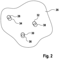
- FIG. 2 A section 26 of a test specimen is shown, which is, for example, welded to a point with an object not shown.
- the corresponding welding points are available as CAD data and are shown in the Fig. 2 symbolized by solid circles 28, 30, 32.
- the position of the actual welding points 34, 36, 38 does not always match the target welding points 28, 30, 32, as is shown by the dashed circles 34, 36, 38.
- the ultrasonic sensor 16 it is necessary for the ultrasonic sensor 16 to be aligned with the actual welding points and then placed on them with the necessary force in order to carry out a proper measurement.
- the position of the actual welding point 34, 36, 38 is determined using the camera and image processing, and its normal direction is determined using runtime measurements.
- the force vector can also be determined using the force-torque sensor system and its alignment along the normal can be achieved by adjusting the test head.
- the ultrasonic sensor 16 is first aligned to the target welding points 28 or 30 or 32, which are derived from CAD data, for example.
- the actual welding point is optically recorded using the camera 22 and its coordinates are determined.
- an image processing algorithm can determine the 2D center of the actual welding point and pass it on to the measuring robot. If there is a deviation between the target and actual value, the robot arm 12 is adjusted accordingly so that the ultrasonic sensor 16 is aligned to the actual welding point 34 or 36 or 38 and can measure it.
- the corresponding deviations can also be used to make corrections during subsequent welding on the same or a corresponding test piece in order to achieve a better match between the target and actual welding points. In this respect, the position at which welding is to take place is corrected.
- measurement results and determined differences between actual and target positions of the welds or weld points can be stored in a customer database and/or in a CAD model that contains the target positions of the welds.
- Fig. 1 In principle, an ultrasonic probe arrangement has been explained to check welds in the form of weld spots, so the Fig. 3 to 7 a preferred embodiment of an ultrasonic probe arrangement 104 as well as further features characterizing the invention can be taken individually and/or in combination, wherein the ultrasonic probe arrangement per se is not covered by the claims.
- weld points are generally referred to below as weld points.
- both the test object 102 and the calibration bodies 108, 110, 112 are recorded using a 3D scanner 107 in order to be able to transform the spatial coordinates of the test object 102 into the coordinate system of the robot 100 from the 3D point cloud or clouds of the 3D scanner 107, whereby the CAD data of the test object 102 and the calibration bodies 108, 110, 112 are included at the same time.
- the CAD data of the calibration bodies 108, 110, 112 are known.
- the spatial coordinates in the robot coordinate system are also available.
- the calibration bodies 108, 110, 112 extend from a holder 113, which is part of the ultrasonic probe assembly 104, which is connected to the flange 106 of the robot 100.
- the probe assembly 104 can be moved to the test object 102 on the basis of the CAD data of the test object.
- the holder with the calibration bodies can be removed after calibration has been completed, so that the mass that has to be moved when measuring or checking the welding points using the robot is reduced.
- the test object 102 is preferably held and fixed by a second robot 118 and can thus be aligned with the first robot 100 in such a way that the measurements can be carried out.
- the 3D point cloud obtained in this way is compared with the CAD data and the component position is determined.
- the CAD data available in the component position-independent format are converted into absolute robot positions using the 3D scanner.
- the coordinates of the test object and its spatial position relative to the robot 100 are available.
- the 6D data in the component coordinate system are exported to the world coordinate system of the robot and are available there.
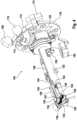
- the probe assembly 104 is described in more detail in the Fig. 4 and 5 shown.
- a base or flange plate 116 which can be connected in a clear spatial arrangement to the robot 100 via centering pins 120, the holder 113 for the calibration bodies 108, 110, 112 and, on the other hand, a carrier 122 which is connected to the plate 116 via a force-torque sensor 123.
- the carrier 122 has a holder 124 in its distal area, which in the exemplary embodiment has an L-geometry with a leg 126 running in the longitudinal axis direction of the carrier 122, which rotatably accommodates an ultrasonic test head 128 with camera 130.
- the camera 130 is rigidly connected to the housing 132 of the ultrasonic test head 128, so that a synchronous movement of the ultrasonic test head 128 and camera 130 takes place, which can be surrounded by a ring illumination on the beam entry side.
- the calibration bodies 108, 110, 112 with the holder 113 can be connected in a fixed manner to the flange 116 via a locking bolt 115, as the drawing clearly shows.
- the ultrasonic probe 128 may be a phased array probe.
- the test head 128 has a water pre-flow section which is surrounded by a housing 134.
- the housing 134 is detachably connected to the housing 132 of the ultrasonic test head 128, e.g. via a knurled nut 136.
- the housing 134 of the pre-flow section has a cover, such as a membrane 140, which is placed on a welding point when measuring it.
- the membrane 140 can also be replaced, e.g. using the knurled nut 142.
- a transmission drive is provided in order to be able to pivot the ultrasonic test head 128 and thus the camera 130.
- a belt 144 is adjusted via an actuator 146.
- the belt 144 is guided by a deflection pulley (not further specified), the axis of which defines the pivot axis 129 of the ultrasonic test head 128.
- a dosing device is integrated in the carrier 122, which has an outlet nozzle 148 through which a wetting liquid can be dispensed in order to wet the membrane 140.
- the wetting medium such as water or oil, is sprayed in a cone shape from the nozzle 148, with the longitudinal axis of the cone 150 coinciding with the longitudinal axis of the carrier 122 or running parallel to it.
- the pivoting or rotational axis 129 of the ultrasonic test head 128 runs perpendicular to this, as can be seen from the drawings.
- a shielding plate 154 extends from the cross leg 152 of the holder 20 connected to the carrier 122, which shielding plate is dimensioned such that when the ultrasonic test head 128 and thus the membrane 140 is aligned with the spray cone 150 of the dosing device with the nozzle 148, the camera 130, i.e. its entrance optics, is shielded so that it cannot be sprayed.
- the connections leading to the ultrasonic probe 128, the camera 130 and the actuator 146 are accommodated by cable guides 156, 158, which simultaneously provide strain relief.
- the ultrasonic test head 128 and, synchronously with it, the camera 130 can be pivoted to the holder 124 and thus to the base plate 116.
- the pivot angle is 0°
- the pivot angle is 90°
- the pivot angle is 180°, in which the membrane 140 is aligned with the spray cone 150 for wetting it.
- the separating plate 154 can be seen, which runs between the camera 130 and the spray cone 150, so that wetting of the optics of the camera 130 is excluded.
- the positions of the ultrasonic probe 128 shown can be set to any position, which allows for optimal alignment of the ultrasonic test head 128 onto a welding point and thus collisions with the test object 102 can be avoided.
- the robot arm 100 can rotate around the axis of the ultrasonic test head 128 at a fixed swivel angle in order to avoid collisions. Overall, this results in two angular degrees of freedom for the collision-free placement of the ultrasonic test head onto a welding point, namely the swivel angle and the rotation angle around the axis of the ultrasonic test head.
- test head 128 is first roughly adjusted on the basis of the CAD data of the weld points, which have been transformed into the coordinates of the robot 100 in the manner described above.
- the test head 128 is adjusted based on the image recorded by the camera 130 and the image processing by means of the software that processes this data, i.e. the member of the robot 100 holding the test head arrangement 104 or its arms, in order to then, after determining the normal emanating from the center of the weld point, place the ultrasonic test head 128 in the normal direction on the weld point as the actual position.
- the normal direction is determined using four sensors. If this is not possible, the force-torque sensor 123 is used. Irrespective of this, both the ultrasonic sensors and the force-torque sensor 123 can be taken into account to determine the normal, so that redundancy is provided.
- the force-torque sensor 123 ensures that any collisions are detected immediately and thus the test head 128 can be moved immediately away from the collision area.
- the communication between the ultrasonic probe 128 and the test object 102 or the weld point ensures that alignment along the normal is ensured during measurement or testing.
- the membrane 140 Before measuring, the membrane 140 can be sprayed by means of the dosing device.
- test head 128 can be pivoted according to the invention.
- the target-actual offset of the welding point can be saved.
- the membrane 140 is wetted before each measurement.
- pre-sorting is carried out to avoid unnecessary travel. Neighbouring welding points are approached one after the other. It is also possible to pre-sort by dividing welding points into groups, with the groups being approached one after the other to check the welding points in them.
- a welding point If it is determined that a welding point does not exist in reality, but has been stored in the CAD model, an error message is generated in order to to update the database.
- a welding point can be created using a robot.
- the 2D positions of several weld points in the image can be detected in order to determine the weld point that is closest to the center of the image.
- a final safety check can be carried out to determine whether the correction suggestion, i.e. the position change to align with the actual welding point based on the image processing, is smaller than an adjustable limit in order to avoid unwanted collisions with implausible correction values.
- the robot moves to the welding point in a single movement at a safe distance from the surface so that the ultrasonic probe is centered and at a defined distance from the welding point.
- the membrane is then placed on the welding point and measured.
- an ultrasonic test head 212 which has a housing 228 comprising a delay line, a membrane 224 and ultrasonic sensors 229 present in a housing 218 or connected to the housing 218, which are connected to an electronic system via a connection (cable 227) in order to emit ultrasonic pulses and to receive reflected ultrasonic pulses and then to be able to evaluate them.
- a rotation axis 231 is shown which passes through the holder 124 in order to be able to pivot the test head 212 by means of the drive 144, 146 to the extent explained above.
- the ultrasonic test head and the optical sensor can be pivoted synchronously, whereby an alignment takes place on a dosing device by means of which a coupling medium can be sprayed onto the cover of the ultrasonic test head.
- Also independently inventive is the determination of the spatial position of the test object having the welds to be measured in relation to the robot having the ultrasonic test head, wherein the CAD data of the test object and the welds are transformed into absolute robot positions, in particular using a 3D scanner, with which the position in space of both the test object and the calibration bodies assigned to the part of the robot holding the ultrasonic test head arrangement are determined, the CAD data of which are known.
- Also inventive is the rough alignment of the ultrasonic head to the welds based on the exported CAD data of the welds and subsequent fine alignment using the optical sensor and image processing as well as the placement of the ultrasonic probe on the weld such as the welding point in the normal direction.
Landscapes
- Engineering & Computer Science (AREA)
- Physics & Mathematics (AREA)
- Mechanical Engineering (AREA)
- General Physics & Mathematics (AREA)
- Chemical & Material Sciences (AREA)
- Analytical Chemistry (AREA)
- Health & Medical Sciences (AREA)
- General Health & Medical Sciences (AREA)
- Life Sciences & Earth Sciences (AREA)
- Immunology (AREA)
- Pathology (AREA)
- Biochemistry (AREA)
- Robotics (AREA)
- Acoustics & Sound (AREA)
- Quality & Reliability (AREA)
- Multimedia (AREA)
- Optics & Photonics (AREA)
- Investigating Or Analyzing Materials By The Use Of Ultrasonic Waves (AREA)
Claims (6)
- Procédé pour le contrôle et/ou la correction d'une soudure (34, 36, 38), telle qu'un point de soudure d'un élément à contrôler (26, 102), tel qu'un véhicule automobile ou d'une ou de plusieurs pièces de celui-ci, comprenant les étapes de procédé suivantes :- orientation d'une tête de contrôle à ultrasons (16, 128) guidée par un robot (100) sur une position de consigne (28, 30, 32) de la soudure,- détermination de la position réelle (34, 36, 38) de la soudure au moyen d'un capteur optique (22, 130) et orientation de la tête de contrôle à ultrasons (16) sur la position réelle et pose de la tête de contrôle à ultrasons dans le sens de la normale de la soudure,- mesure de la soudure,caractérisé en ce
que les données CAO de la position de consigne de la soudure (28, 30, 32) sont fournies, que sur la base des données CAO de la soudure, la tête de contrôle à ultrasons (16, 128) est orientée sur la position de consigne de la soudure et qu'après la détermination de la position réelle (34, 36, 38) de la soudure au moyen du capteur optique (22, 130), la tête de contrôle à ultrasons est posée sur la soudure avec une force régulée, sachant que sont associés au robot (100) de manière fixe un ou plusieurs corps de calibrage (108, 110, 112) des données CAO connues, que le ou les corps de calibrage sont mesurés en même temps que l'élément à contrôler (26, 102) ou l'une ou plusieurs pièces de l'élément à contrôler au moyen d'une caméra ou d'un scanner 3D (107), et que la position de l'élément à contrôler est déterminée au moyen des images 2D de la caméra ou du nuage de points 3D du scanner 3D et est transformée dans le système de coordonnées du robot en tenant compte des données CAO de l'élément à contrôler et que pour poser la tête de contrôle à ultrasons (16, 128) dans le sens de la normale de la soudure (34, 36, 38), le sens de la normale est déterminé au moyen de capteurs à ultrasons de la tête de contrôle à ultrasons (16, 128) et/ou en déterminant la direction du vecteur de la force s'exerçant sur la soudure au moyen d'au moins un capteur de force et/ou de couple (20, 123). - Procédé selon la revendication 1,
caractérisé en ce
que lors de la mesure de la soudure, la tête de contrôle à ultrasons (16, 128) agit sur la soudure avec une force P telle que P ≤ 30 N, notamment 5 N ≤ P ≤ 15 N, de préférence P comprise dans la plage 5 N - 10 N. - Procédé selon la revendication 1 ou 2,
caractérisé en ce
que lors d'un contrôle de plusieurs points de soudure pour contrôler ceux-ci, un pré-tri a lieu de telle sorte qu'après le contrôle d'un point de soudure, le point le plus proche du point de soudure précédemment contrôlé est contrôlé, et/ou que les points de soudure sont répartis en groupes, sachant que de préférence, l'écart entre les points de soudure dans des groupes respectifs est inférieur à l'écart entre les groupes, et/ou que les points de soudure sont déterminés en fonction des erreurs de soudure, telles que des ardillons, et qu'une mesure d'une soudure présentant une erreur de soudure n'est pas effectuée. - Procédé selon au moins l'une des revendications précédentes,
caractérisé en ce
que l'élément à contrôler (102) est tenu par un second robot (118) de telle sorte que le robot (100) guidant la tête de contrôle à ultrasons (128) atteint un optimum, dans le cas échéant l'ensemble ou au moins une multitude des soudures à contrôler. - Procédé selon au moins l'une des revendications précédentes,
caractérisé en ce
que la tête de contrôle à ultrasons est conçue de manière à être pivotable par rapport au robot, sachant que des collisions avec l'élément à contrôler sont évitées en basculant la tête de contrôle à ultrasons. - Procédé selon au moins l'une des revendications précédentes,
caractérisé en ce
que la tête de contrôle à ultrasons et le capteur optique sont basculés de manière synchrone et notamment que le capteur optique, telle que la caméra, est relié à la tête de contrôle à ultrasons.
Applications Claiming Priority (2)
| Application Number | Priority Date | Filing Date | Title |
|---|---|---|---|
| DE102019104654.8A DE102019104654A1 (de) | 2019-02-25 | 2019-02-25 | Verfahren zur Überprüfung einer Schweißung |
| DE202020100206.6U DE202020100206U1 (de) | 2020-01-16 | 2020-01-16 | Ultraschallprüfkopfanordnung |
Publications (4)
| Publication Number | Publication Date |
|---|---|
| EP3699585A2 EP3699585A2 (fr) | 2020-08-26 |
| EP3699585A3 EP3699585A3 (fr) | 2020-10-07 |
| EP3699585C0 EP3699585C0 (fr) | 2025-03-05 |
| EP3699585B1 true EP3699585B1 (fr) | 2025-03-05 |
Family
ID=69779755
Family Applications (1)
| Application Number | Title | Priority Date | Filing Date |
|---|---|---|---|
| EP20158655.9A Active EP3699585B1 (fr) | 2019-02-25 | 2020-02-21 | Procédé de vérification d'un soudage |
Country Status (6)
| Country | Link |
|---|---|
| US (1) | US11656205B2 (fr) |
| EP (1) | EP3699585B1 (fr) |
| CN (1) | CN111610251B (fr) |
| CA (1) | CA3073681A1 (fr) |
| MX (1) | MX2020002026A (fr) |
| ZA (1) | ZA202001126B (fr) |
Families Citing this family (8)
| Publication number | Priority date | Publication date | Assignee | Title |
|---|---|---|---|---|
| DE102018120479B4 (de) * | 2018-08-22 | 2024-07-11 | Benteler Automobiltechnik Gmbh | Verfahren zur Herstellung einer Achskomponente |
| US11584013B2 (en) * | 2020-03-31 | 2023-02-21 | Wipro Limited | System, device and method for determining error in robotic manipulator-to-camera calibration |
| CN113219059B (zh) * | 2021-05-18 | 2023-04-07 | 内蒙古电力(集团)有限责任公司内蒙古电力科学研究院分公司 | 一种电站汽轮机厚壁隔板相控阵检测工艺方法 |
| JP7658823B2 (ja) * | 2021-07-19 | 2025-04-08 | 株式会社東芝 | 処理システム、ロボットシステム、制御装置、処理方法、制御方法、プログラム、及び記憶媒体 |
| JP7853542B2 (ja) | 2021-10-29 | 2026-04-30 | 株式会社デンソーウェーブ | ロボット |
| AT527784A1 (de) * | 2023-12-06 | 2025-06-15 | Fill Gmbh | Verfahren zum zerstörungsfreien Prüfen eines Bauteils, sowie eine Ultraschall-Prüfanlage zum zerstörungsfreien Prüfen des Bauteils |
| CN119198920B (zh) * | 2024-09-30 | 2026-04-21 | 中国航发北京航空材料研究院 | 一种超声极扫描装置及超声极扫描检测方法 |
| CN119897716B (zh) * | 2025-03-28 | 2025-07-22 | 伯芯微电子(天津)有限公司 | 一种芯片焊接方法及其焊接装置 |
Family Cites Families (25)
| Publication number | Priority date | Publication date | Assignee | Title |
|---|---|---|---|---|
| GB1270387A (en) * | 1968-06-07 | 1972-04-12 | Int Research & Dev Co Ltd | Improvements in and relating to ultrasonic apparatus for the inspection of welds |
| DE3122408A1 (de) * | 1981-06-05 | 1982-12-23 | Ernst Leitz Wetzlar Gmbh, 6330 Wetzlar | Verfahren und vorrichtung zur reinigung und benetzung der frontflaeche eines ultraschall-objektives |
| US4796200A (en) * | 1986-12-09 | 1989-01-03 | Diffracto Ltd. | Target based determination of robot and sensor alignment |
| JPH02263157A (ja) * | 1989-04-03 | 1990-10-25 | Mitsubishi Electric Corp | 検査装置 |
| US5798627A (en) * | 1995-01-04 | 1998-08-25 | Gilliland; Malcolm T. | Method for simultaneous operation of robot welders |
| JP4874499B2 (ja) * | 2000-07-14 | 2012-02-15 | ロッキード マーティン コーポレイション | 試験目的の超音波信号発生装置を配置し位置決めするためのシステムおよび方法 |
| DE10125782B4 (de) | 2000-10-25 | 2004-12-23 | SCHWEIßTECHNISCHE LEHR- UND VERSUCHSANSTALT HALLE GMBH | Verfahren zur automatisierten Ultraschallprüfung von Widerstandspunktschweißverbindungen |
| US7132617B2 (en) * | 2002-02-20 | 2006-11-07 | Daimlerchrysler Corporation | Method and system for assessing quality of spot welds |
| DE102004044342B4 (de) | 2004-03-24 | 2006-03-23 | Slv Halle Gmbh | Anordnung und Verfahren zum automatisierten Ultraschall-Prüfen räumlich geformter strahlgeschweißter Bauteile |
| US7395714B2 (en) | 2004-09-16 | 2008-07-08 | The Boeing Company | Magnetically attracted inspecting apparatus and method using a ball bearing |
| US8989897B2 (en) * | 2004-11-19 | 2015-03-24 | Dynalog, Inc. | Robot-cell calibration |
| JP3886014B2 (ja) * | 2005-02-14 | 2007-02-28 | 株式会社エクセディ | 自動超音波検査装置、その検査方法及びその検査方法を用いた製造方法 |
| DE102005043776A1 (de) * | 2005-09-14 | 2007-03-22 | Bayerische Motoren Werke Ag | Verfahren zur Positionierung eines Ultraschallprüfkopfes |
| JP2007152371A (ja) * | 2005-12-01 | 2007-06-21 | Kanto Auto Works Ltd | 溶接打点位置検査システム |
| JP5456259B2 (ja) * | 2008-01-30 | 2014-03-26 | 日野自動車株式会社 | 溶接検査方法および装置 |
| US8146429B2 (en) * | 2009-08-03 | 2012-04-03 | Georgia Tech Research Corporation | Methods and systems for classifying the type and severity of defects in welds |
| DE102009051097A1 (de) * | 2009-10-28 | 2011-05-05 | Ge Sensing & Inspection Technologies Gmbh | Verbesserte Koppelmediumversorgung einer Ultraschallprüfvorrichtung |
| EP2322897A1 (fr) * | 2009-11-11 | 2011-05-18 | Günther Battenberg | Dispositif et procédé destinés à la mesure de pièces à usiner basé sur une machine pour mesurer des coordonnées optiques et mécaniques |
| US9182487B2 (en) * | 2011-06-22 | 2015-11-10 | The Boeing Company | Advanced remote nondestructive inspection system and process |
| US9759540B2 (en) * | 2014-06-11 | 2017-09-12 | Hexagon Metrology, Inc. | Articulating CMM probe |
| CN104792869B (zh) * | 2015-04-03 | 2018-01-05 | 上海和伍精密仪器股份有限公司 | 低压电器电触头钎焊质量的超声波无损检测系统 |
| US10036731B2 (en) | 2016-03-31 | 2018-07-31 | Honda Motor Co., Ltd. | Weld testing system and method for a welding assembly |
| DE102017125033A1 (de) | 2017-10-25 | 2019-04-25 | ese-robotics GmbH | Verfahren und Industrieroboter zur Prüfung von Schweißverbindungen, insbesondere von Schweißpunkten |
| JP6570600B2 (ja) | 2017-11-15 | 2019-09-04 | 株式会社東芝 | 検査システム、制御装置、角度調整方法、プログラム、および記憶媒体 |
| EP3702726A1 (fr) * | 2019-02-28 | 2020-09-02 | Renishaw PLC | Procédé de calibration d'une sonde ultrasonique et dispositif d'inspection correspondant |
-
2020
- 2020-02-21 MX MX2020002026A patent/MX2020002026A/es unknown
- 2020-02-21 EP EP20158655.9A patent/EP3699585B1/fr active Active
- 2020-02-24 ZA ZA2020/01126A patent/ZA202001126B/en unknown
- 2020-02-24 US US16/798,582 patent/US11656205B2/en active Active
- 2020-02-25 CA CA3073681A patent/CA3073681A1/fr active Pending
- 2020-02-25 CN CN202010116624.5A patent/CN111610251B/zh active Active
Also Published As
| Publication number | Publication date |
|---|---|
| CN111610251A (zh) | 2020-09-01 |
| US20200271627A1 (en) | 2020-08-27 |
| CN111610251B (zh) | 2024-11-12 |
| EP3699585A3 (fr) | 2020-10-07 |
| CA3073681A1 (fr) | 2020-08-25 |
| EP3699585C0 (fr) | 2025-03-05 |
| EP3699585A2 (fr) | 2020-08-26 |
| ZA202001126B (en) | 2021-03-31 |
| MX2020002026A (es) | 2020-08-26 |
| US11656205B2 (en) | 2023-05-23 |
Similar Documents
| Publication | Publication Date | Title |
|---|---|---|
| EP3699585B1 (fr) | Procédé de vérification d'un soudage | |
| EP3062959B1 (fr) | Procédé et dispositif de détection et de correction d'une position dans l'espace d'une pièce maintenue dans un système de positionnement | |
| DE102019211028B4 (de) | Robotersystem und Kalibrierverfahren | |
| DE102015119240B3 (de) | Automatisches detektieren und robotergestütztes bearbeiten von oberflächendefekten | |
| DE102015012565B3 (de) | Vorrichtung und Verfahren zur Erhöhung der Genauigkeit eines OCT-Messsystems für die Lasermaterialbearbeitung | |
| EP0770445B1 (fr) | Méthode de contrôle et de positionnement d'un faisceau ou d'un jet pour l'usinage d'une pièce | |
| DE102017126867A1 (de) | Laserbearbeitungssystem und Verfahren zur Laserbearbeitung | |
| EP3463811B1 (fr) | Procédé et dispositif de fabrication additive de pièces | |
| DE4428363C2 (de) | Röntgen-Mikrodiffraktometer | |
| DE102018122627B4 (de) | Messsystem | |
| DE102018202203B4 (de) | Anordnung zur Justierung einer Pulverströmung in Bezug zur mittleren Längsachse eines Energiestrahls | |
| WO2014114737A2 (fr) | Procédé et dispositif de détermination de la géométrie de structures au moyen de la tomographie assistée par ordinateur | |
| DE102004007830B4 (de) | Verfahren zur Lokalisierung von Fehlstellen und Markiersystem | |
| DE102007023826A1 (de) | Verfahren und Vorrichtung zur berührungslosen Schwingungsmessung | |
| EP1238746A2 (fr) | Méthode et appareil de découpe et soudage laser à commande robotique | |
| WO2009080233A1 (fr) | Procédé et dispositif d'assemblage | |
| DE102006018558B4 (de) | Verfahren zum automatischen Aufbringen oder Erzeugen und Überwachen einer auf einem Substrat aufgebrachten Struktur mit Ermittlung von geometrischen Abmessungen | |
| DE102008019435B4 (de) | Verfahren zum berührungslosen Vermessen dreidimensionaler, komplex geformter Bauteile | |
| EP3710777B1 (fr) | Dispositif pour la mesure optique du profil de filetage extérieur de tubes | |
| WO2019120557A1 (fr) | Dispositif optique d'application ou de production et de surveillance automatiques d'une structure déposée sur un substrat avec détermination de dimensions géométriques et procédé correspondant | |
| DE10115043A1 (de) | Verfahren und Vorrichtung zur Kalibrierung eines Kamerasystems, insbesondere eines auf einem Fahrzeug angeordneten Kamerasystems | |
| DE102004044342B4 (de) | Anordnung und Verfahren zum automatisierten Ultraschall-Prüfen räumlich geformter strahlgeschweißter Bauteile | |
| EP1399287B1 (fr) | Procede de coupe au rayonnement laser de pieces a assembler | |
| DE102019104654A1 (de) | Verfahren zur Überprüfung einer Schweißung | |
| EP4339556B1 (fr) | Procédé et dispositif de détermination de propriétés de surface d'une pièce |
Legal Events
| Date | Code | Title | Description |
|---|---|---|---|
| PUAI | Public reference made under article 153(3) epc to a published international application that has entered the european phase |
Free format text: ORIGINAL CODE: 0009012 |
|
| STAA | Information on the status of an ep patent application or granted ep patent |
Free format text: STATUS: THE APPLICATION HAS BEEN PUBLISHED |
|
| AK | Designated contracting states |
Kind code of ref document: A2 Designated state(s): AL AT BE BG CH CY CZ DE DK EE ES FI FR GB GR HR HU IE IS IT LI LT LU LV MC MK MT NL NO PL PT RO RS SE SI SK SM TR |
|
| AX | Request for extension of the european patent |
Extension state: BA ME |
|
| PUAL | Search report despatched |
Free format text: ORIGINAL CODE: 0009013 |
|
| AK | Designated contracting states |
Kind code of ref document: A3 Designated state(s): AL AT BE BG CH CY CZ DE DK EE ES FI FR GB GR HR HU IE IS IT LI LT LU LV MC MK MT NL NO PL PT RO RS SE SI SK SM TR |
|
| AX | Request for extension of the european patent |
Extension state: BA ME |
|
| RIC1 | Information provided on ipc code assigned before grant |
Ipc: B23K 11/25 20060101ALI20200828BHEP Ipc: G01N 29/22 20060101ALI20200828BHEP Ipc: G01N 29/28 20060101ALI20200828BHEP Ipc: G01N 29/04 20060101AFI20200828BHEP Ipc: B23K 1/00 20060101ALI20200828BHEP Ipc: B23K 37/00 20060101ALI20200828BHEP Ipc: G01N 29/265 20060101ALI20200828BHEP |
|
| STAA | Information on the status of an ep patent application or granted ep patent |
Free format text: STATUS: REQUEST FOR EXAMINATION WAS MADE |
|
| 17P | Request for examination filed |
Effective date: 20210324 |
|
| RBV | Designated contracting states (corrected) |
Designated state(s): AL AT BE BG CH CY CZ DE DK EE ES FI FR GB GR HR HU IE IS IT LI LT LU LV MC MK MT NL NO PL PT RO RS SE SI SK SM TR |
|
| STAA | Information on the status of an ep patent application or granted ep patent |
Free format text: STATUS: EXAMINATION IS IN PROGRESS |
|
| 17Q | First examination report despatched |
Effective date: 20221128 |
|
| P01 | Opt-out of the competence of the unified patent court (upc) registered |
Effective date: 20230728 |
|
| RIC1 | Information provided on ipc code assigned before grant |
Ipc: B23K 103/10 20060101ALI20240326BHEP Ipc: B23K 103/04 20060101ALI20240326BHEP Ipc: B23K 101/18 20060101ALI20240326BHEP Ipc: B23K 101/00 20060101ALI20240326BHEP Ipc: B23K 31/12 20060101ALI20240326BHEP Ipc: B23K 11/18 20060101ALI20240326BHEP Ipc: B23K 11/16 20060101ALI20240326BHEP Ipc: G01N 29/28 20060101ALI20240326BHEP Ipc: B23K 11/11 20060101ALI20240326BHEP Ipc: B23K 11/00 20060101ALI20240326BHEP Ipc: G01N 29/265 20060101ALI20240326BHEP Ipc: G01N 29/22 20060101ALI20240326BHEP Ipc: G01N 29/04 20060101AFI20240326BHEP |
|
| GRAP | Despatch of communication of intention to grant a patent |
Free format text: ORIGINAL CODE: EPIDOSNIGR1 |
|
| STAA | Information on the status of an ep patent application or granted ep patent |
Free format text: STATUS: GRANT OF PATENT IS INTENDED |
|
| INTG | Intention to grant announced |
Effective date: 20240506 |
|
| GRAJ | Information related to disapproval of communication of intention to grant by the applicant or resumption of examination proceedings by the epo deleted |
Free format text: ORIGINAL CODE: EPIDOSDIGR1 |
|
| STAA | Information on the status of an ep patent application or granted ep patent |
Free format text: STATUS: EXAMINATION IS IN PROGRESS |
|
| GRAS | Grant fee paid |
Free format text: ORIGINAL CODE: EPIDOSNIGR3 |
|
| STAA | Information on the status of an ep patent application or granted ep patent |
Free format text: STATUS: GRANT OF PATENT IS INTENDED |
|
| GRAP | Despatch of communication of intention to grant a patent |
Free format text: ORIGINAL CODE: EPIDOSNIGR1 |
|
| INTC | Intention to grant announced (deleted) | ||
| RIN1 | Information on inventor provided before grant (corrected) |
Inventor name: BATTENBERG, GUENTHER |
|
| INTG | Intention to grant announced |
Effective date: 20240927 |
|
| GRAA | (expected) grant |
Free format text: ORIGINAL CODE: 0009210 |
|
| STAA | Information on the status of an ep patent application or granted ep patent |
Free format text: STATUS: THE PATENT HAS BEEN GRANTED |
|
| AK | Designated contracting states |
Kind code of ref document: B1 Designated state(s): AL AT BE BG CH CY CZ DE DK EE ES FI FR GB GR HR HU IE IS IT LI LT LU LV MC MK MT NL NO PL PT RO RS SE SI SK SM TR |
|
| REG | Reference to a national code |
Ref country code: GB Ref legal event code: FG4D Free format text: NOT ENGLISH |
|
| REG | Reference to a national code |
Ref country code: CH Ref legal event code: EP |
|
| REG | Reference to a national code |
Ref country code: DE Ref legal event code: R096 Ref document number: 502020010513 Country of ref document: DE |
|
| REG | Reference to a national code |
Ref country code: IE Ref legal event code: FG4D Free format text: LANGUAGE OF EP DOCUMENT: GERMAN |
|
| U01 | Request for unitary effect filed |
Effective date: 20250325 |
|
| U07 | Unitary effect registered |
Designated state(s): AT BE BG DE DK EE FI FR IT LT LU LV MT NL PT RO SE SI Effective date: 20250331 |
|
| P04 | Withdrawal of opt-out of the competence of the unified patent court (upc) registered |
Free format text: CASE NUMBER: APP_14855/2025 Effective date: 20250326 |
|
| PG25 | Lapsed in a contracting state [announced via postgrant information from national office to epo] |
Ref country code: RS Free format text: LAPSE BECAUSE OF FAILURE TO SUBMIT A TRANSLATION OF THE DESCRIPTION OR TO PAY THE FEE WITHIN THE PRESCRIBED TIME-LIMIT Effective date: 20250605 |
|
| PG25 | Lapsed in a contracting state [announced via postgrant information from national office to epo] |
Ref country code: ES Free format text: LAPSE BECAUSE OF FAILURE TO SUBMIT A TRANSLATION OF THE DESCRIPTION OR TO PAY THE FEE WITHIN THE PRESCRIBED TIME-LIMIT Effective date: 20250305 |
|
| PG25 | Lapsed in a contracting state [announced via postgrant information from national office to epo] |
Ref country code: NO Free format text: LAPSE BECAUSE OF FAILURE TO SUBMIT A TRANSLATION OF THE DESCRIPTION OR TO PAY THE FEE WITHIN THE PRESCRIBED TIME-LIMIT Effective date: 20250605 |
|
| PG25 | Lapsed in a contracting state [announced via postgrant information from national office to epo] |
Ref country code: HR Free format text: LAPSE BECAUSE OF FAILURE TO SUBMIT A TRANSLATION OF THE DESCRIPTION OR TO PAY THE FEE WITHIN THE PRESCRIBED TIME-LIMIT Effective date: 20250305 |
|
| PG25 | Lapsed in a contracting state [announced via postgrant information from national office to epo] |
Ref country code: GR Free format text: LAPSE BECAUSE OF FAILURE TO SUBMIT A TRANSLATION OF THE DESCRIPTION OR TO PAY THE FEE WITHIN THE PRESCRIBED TIME-LIMIT Effective date: 20250606 |
|
| PG25 | Lapsed in a contracting state [announced via postgrant information from national office to epo] |
Ref country code: SM Free format text: LAPSE BECAUSE OF FAILURE TO SUBMIT A TRANSLATION OF THE DESCRIPTION OR TO PAY THE FEE WITHIN THE PRESCRIBED TIME-LIMIT Effective date: 20250305 |
|
| PG25 | Lapsed in a contracting state [announced via postgrant information from national office to epo] |
Ref country code: PL Free format text: LAPSE BECAUSE OF FAILURE TO SUBMIT A TRANSLATION OF THE DESCRIPTION OR TO PAY THE FEE WITHIN THE PRESCRIBED TIME-LIMIT Effective date: 20250305 |
|
| PG25 | Lapsed in a contracting state [announced via postgrant information from national office to epo] |
Ref country code: CZ Free format text: LAPSE BECAUSE OF FAILURE TO SUBMIT A TRANSLATION OF THE DESCRIPTION OR TO PAY THE FEE WITHIN THE PRESCRIBED TIME-LIMIT Effective date: 20250305 |
|
| PG25 | Lapsed in a contracting state [announced via postgrant information from national office to epo] |
Ref country code: SK Free format text: LAPSE BECAUSE OF FAILURE TO SUBMIT A TRANSLATION OF THE DESCRIPTION OR TO PAY THE FEE WITHIN THE PRESCRIBED TIME-LIMIT Effective date: 20250305 |
|
| PG25 | Lapsed in a contracting state [announced via postgrant information from national office to epo] |
Ref country code: IS Free format text: LAPSE BECAUSE OF FAILURE TO SUBMIT A TRANSLATION OF THE DESCRIPTION OR TO PAY THE FEE WITHIN THE PRESCRIBED TIME-LIMIT Effective date: 20250705 |
|
| PLBE | No opposition filed within time limit |
Free format text: ORIGINAL CODE: 0009261 |
|
| STAA | Information on the status of an ep patent application or granted ep patent |
Free format text: STATUS: NO OPPOSITION FILED WITHIN TIME LIMIT |
|
| REG | Reference to a national code |
Ref country code: CH Ref legal event code: L10 Free format text: ST27 STATUS EVENT CODE: U-0-0-L10-L00 (AS PROVIDED BY THE NATIONAL OFFICE) Effective date: 20260114 |
|
| 26N | No opposition filed |
Effective date: 20251208 |