EP3699863B1 - Bildinterpretationsvorrichtung - Google Patents
Bildinterpretationsvorrichtung Download PDFInfo
- Publication number
- EP3699863B1 EP3699863B1 EP17929925.0A EP17929925A EP3699863B1 EP 3699863 B1 EP3699863 B1 EP 3699863B1 EP 17929925 A EP17929925 A EP 17929925A EP 3699863 B1 EP3699863 B1 EP 3699863B1
- Authority
- EP
- European Patent Office
- Prior art keywords
- data
- pixels
- pieces
- aligned along
- channels
- Prior art date
- Legal status (The legal status is an assumption and is not a legal conclusion. Google has not performed a legal analysis and makes no representation as to the accuracy of the status listed.)
- Active
Links
Images


Classifications
-
- G—PHYSICS
- G06—COMPUTING OR CALCULATING; COUNTING
- G06T—IMAGE DATA PROCESSING OR GENERATION, IN GENERAL
- G06T7/00—Image analysis
- G06T7/0002—Inspection of images, e.g. flaw detection
- G06T7/0012—Biomedical image inspection
-
- G—PHYSICS
- G01—MEASURING; TESTING
- G01N—INVESTIGATING OR ANALYSING MATERIALS BY DETERMINING THEIR CHEMICAL OR PHYSICAL PROPERTIES
- G01N33/00—Investigating or analysing materials by specific methods not covered by groups G01N1/00 - G01N31/00
- G01N33/48—Biological material, e.g. blood, urine; Haemocytometers
-
- G—PHYSICS
- G06—COMPUTING OR CALCULATING; COUNTING
- G06T—IMAGE DATA PROCESSING OR GENERATION, IN GENERAL
- G06T2207/00—Indexing scheme for image analysis or image enhancement
- G06T2207/10—Image acquisition modality
- G06T2207/10056—Microscopic image
-
- G—PHYSICS
- G06—COMPUTING OR CALCULATING; COUNTING
- G06T—IMAGE DATA PROCESSING OR GENERATION, IN GENERAL
- G06T2207/00—Indexing scheme for image analysis or image enhancement
- G06T2207/20—Special algorithmic details
- G06T2207/20021—Dividing image into blocks, subimages or windows
-
- G—PHYSICS
- G06—COMPUTING OR CALCULATING; COUNTING
- G06T—IMAGE DATA PROCESSING OR GENERATION, IN GENERAL
- G06T2207/00—Indexing scheme for image analysis or image enhancement
- G06T2207/20—Special algorithmic details
- G06T2207/20076—Probabilistic image processing
-
- G—PHYSICS
- G06—COMPUTING OR CALCULATING; COUNTING
- G06T—IMAGE DATA PROCESSING OR GENERATION, IN GENERAL
- G06T2207/00—Indexing scheme for image analysis or image enhancement
- G06T2207/20—Special algorithmic details
- G06T2207/20081—Training; Learning
-
- G—PHYSICS
- G06—COMPUTING OR CALCULATING; COUNTING
- G06T—IMAGE DATA PROCESSING OR GENERATION, IN GENERAL
- G06T2207/00—Indexing scheme for image analysis or image enhancement
- G06T2207/20—Special algorithmic details
- G06T2207/20084—Artificial neural networks [ANN]
-
- G—PHYSICS
- G06—COMPUTING OR CALCULATING; COUNTING
- G06T—IMAGE DATA PROCESSING OR GENERATION, IN GENERAL
- G06T2207/00—Indexing scheme for image analysis or image enhancement
- G06T2207/30—Subject of image; Context of image processing
- G06T2207/30004—Biomedical image processing
- G06T2207/30024—Cell structures in vitro; Tissue sections in vitro
Definitions
- the description herein discloses an image analysis device configured to execute image analysis according to a convolutional neural network.
- image analysis that uses an image analysis device is known (for example, Japanese Patent Application Publication Nos. 2001-59842 , 2010-281636 , 2004- 286666 , and 2011-527056 ).
- Japanese Patent Application Publication No. 2011-527056 executes image analysis according to a convolutional neural network.
- Yuezhang Li ET AL "Object-sensitive Deep Reinforcement Learning", 3rd Global Conference on Artificial Intelligence (GCAI-17), EPiC Series in Computing, 18 October 2017 (2017-10-18), pages 20-35 , XP055726730, relates to object-sensitive deep reinforcement learning.
- a consideration may be given for example to executing the image analysis by generating reduced image data by reducing target image data of an analysis target and executing the image analysis according to the convolutional neural network using the reduced image data.
- the image analysis using the reduced image data may have degraded analysis accuracy.
- An image analysis device comprising a memory, an obtaining unit, a specifying unit, a generating unit, a reducing unit, an analysis unit and an output unit specified according to claim 1 is disclosed herein.
- the image analysis device upon execution of the image analysis according to the convolutional neural network, not only uses the reduced image data as the K pieces of channel data corresponding to the K channels but also uses the first probability data as the one piece of channel data corresponding to the one channel. Due to this, the image analysis device can improve analysis accuracy related to the first object in the image analysis using reduced image data.
- the K channels may be three channels of RGB. According to this configuration, the image analysis device can execute the image analysis by using the reduced image data as three pieces of channel data corresponding to the three channels of RGB.
- the memory may be further configured to store second object data representing a second object different from the first object.
- the image analysis device may further comprise: a second generating unit configured to generate second probability data by using the (m ⁇ n) partial images and the second object data in the memory, wherein the second probability data includes (m ⁇ n) pixels constituted of m pixels aligned along the first direction and n pixels aligned along the second direction, and each pixel of the (m ⁇ n) pixels included in the second probability data indicates a value related to a probability that one partial image corresponding to the pixel includes the second object.
- the analysis unit may execute the image analysis by using the reduced image data as the K pieces of channel data, using the first probability data as the one piece of channel data corresponding to the one channel, and using the second probability data as one piece of channel data corresponding to one channel.
- the image analysis device can improve both the analysis accuracy related to the first object and analysis accuracy related to the second object in the image analysis using reduced image data.
- the first object may be a predetermined cell. According to this configuration, the image analysis device can improve the analysis accuracy related to the first object being the predetermined cell.
- the present technology is also applicable to an image analysis method, as specified in claim 6.
- a computer program as specified in claim 5 is also disclosed.
- FIG. 1 shows a configuration of an image analysis device 10 configured to execute image analysis on an image including cell(s).
- the image analysis device 10 comprises an operation unit 12, a display 14, an input unit 16, and a controller 30.
- the respective units 12 to 30 are connected to a bus line (reference sign omitted).
- the operation unit 12 comprises a mouse and a keyboard, for example.
- a user can provide various instructions to the image analysis device 10 by operating the operation unit 12.
- the display 14 is a display configured to display various types of information.
- the input unit 16 is a device configured to input target image data representing a target image being an analysis target to the image analysis device 10.
- the target image data includes a plurality of cell objects corresponding to a plurality of cells.
- the input unit 16 may be a communication interface configured to execute wired or wireless communication, or may be a memory interface to which a USB memory or the like is to be inserted.
- the target image data may be inputted to the image analysis device 10 by the input unit 16 executing wired or wireless communication with a device storing image data captured by a microscope, a Whole Slide Image (virtual slide) captured by a scanner, and the like, as the target image data and receiving the target image data from this device.
- the target image data may be inputted to the image analysis device 10 by the input unit 16 reading the target image data from a memory storing the target image data.
- the controller 30 comprises a CPU 32 and a memory 34.
- the CPU 32 is configured to execute various processes in accordance with programs 36, 38 stored in the memory 34.
- the memory 34 stores an OS program 36 for realizing basic operations of the image analysis device 10 and an analysis program 38 for executing image analysis according to a convolutional neural network (hereinbelow termed "CNN (abbreviation of Convolutional Neural Network)").
- CNN abbreviation of Convolutional Neural Network
- the image analysis according to the CNN is a concept that encompasses image analysis according to a large-scale network including the CNN as a partial structure thereof (such as GoogLeNet (registered trademark) and Residual Network).
- the image analysis device 10 may be realized by installing the analysis program 38 on a general-purpose PC or server.
- the memory 34 stores analysis data 40 for executing the image analysis according to the analysis program 38.
- the analysis data 40 may be data provided from a vendor who sells the analysis program 38 or may be data generated by the user of the image analysis device 10. In the former case, the analysis data 40 is stored in the memory 34 upon installation of the analysis program 38. In the latter case, the analysis data 40 is stored in the memory 34 by the user of the image analysis device 10 after the installation of the analysis program 38.
- the analysis data 40 includes pattern data 42 and object data 44.
- the pattern data 42 is data used in a convolutional layer in the image analysis according to the CNN.
- the object data 44 includes object data representing images including cell objects respectively indicating types of plural cells (such as a cancer cell, a lymphocyte, and a normal epitheliocyte).
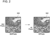
- FIG. 2 shows an example of a target image 500 represented by the target image data.
- the target image data includes (802 ⁇ 802) pixels constituted of 802 pixels aligned along a lateral direction and 802 pixels aligned along a vertical direction.
- target image data may have pixels in numbers different from 802 aligned along the lateral and vertical directions.
- a number of pixels aligned along the lateral direction and a number of pixels aligned along the vertical direction may be different from each other.
- Each of the pixels indicates RGB values in a multilevel gradation (such as 256-level gradation). That is, each pixel indicates three values corresponding to three channels being RGB (that is, the RGB values).
- FIG. 2 shows an example of a reduced image 502 represented by the reduced image data.
- the reduced image data includes (40 ⁇ 40) pixels constituted of 40 pixels aligned along the lateral direction and 40 pixels aligned along the vertical direction.
- pixels in numbers different from 40 may be aligned along the lateral and vertical directions.
- a number of pixels aligned along the lateral direction and a number of pixels aligned along the vertical direction may be different from each other.
- the image analysis device executes the following processes (1) to (5) by using the reduced image data as three pieces of channel data corresponding to the three channels.
- (1) the image analysis device firstly executes a convolutional layer process on the reduced image data.
- Three-layer pattern data included in the pattern data 42 is used in a convolutional layer hereof.
- FIG. 3(A) shows an example of the three-layer pattern data.
- the three-layer pattern data may for example be data for detecting features of a cancer cell (such as edge and texture thereof), and includes one layer of data corresponding to R values, one layer of data corresponding to G values, and one layer of data corresponding to B values.
- Each of the three layers of data includes (3 ⁇ 3) pixels constituted of 3 pixels aligned along the lateral direction and 3 pixels aligned along the vertical direction. That is, the three-layer pattern data is constituted of (3 ⁇ 3 ⁇ 3) pixels. Each pixel indicates a value in the multilevel gradation (such as 256-level gradation).
- FIG. 3(A) shows values of the respective pixels by darkness of color.
- the image analysis device specifies the (3 ⁇ 3) pixels included in the reduced image data as a target pixel group, and compares (3 ⁇ 3) R values included in this target pixel group with the (3 ⁇ 3) R values included in the one layer corresponding to the R values in the three-layer pattern data. Similarly, the image analysis device executes comparisons for the G values and the B values as well.
- the image analysis device uses the comparison results of the RGB to calculate a match rate between the target pixel group and the three-layer pattern data.
- the match rate is represented by a value in a range of "0" to "1".
- the image analysis device generates a primary feature map 101 in which respective match rates as specified are described by sequentially specifying target pixel groups from the reduced image data to sequentially specify the match rates thereof.
- the primary feature map 101 includes (40 ⁇ 40) pixels constituted of 40 pixels aligned along the lateral direction and 40 pixels aligned along the vertical direction, and each pixel indicates the match rate.
- a plurality of pieces of three-layer pattern data is prepared rather than just one piece of three-layer pattern data.
- a plurality of pieces of three-layer pattern data corresponding to different features (such as edge and texture) of a same cell (such as the cancer cell) may be prepared.
- a plurality of pieces of three-layer pattern data corresponding to a feature (such as edge or texture) of plural types of cells may be prepared.
- the image analysis device generates a plurality of primary feature maps 101 to 104 corresponding to the plurality of pieces of three-layer pattern data by executing the convolutional layer process respectively on the plurality of pieces of three-layer pattern data.
- the image analysis is executed by using the reduced image data in which the target image data is reduced, for purpose of speeding up the image analysis.
- a contour and the like of the object may become unclear in a reduced image 502 as compared to a target image 500, by which analysis accuracy may be degraded.
- the present embodiment executes the following processes in addition to the conventional image analysis.
- the CPU 32 shifts 18 pixels downward from the first partial image 510 and specifies a next partial image from the target image 500. Then, similar to the above, the CPU 32 scans rightward from this partial image and sequentially specifies 40 partial images aligned along the lateral direction. By repeating the above, the CPU 32 sequentially specifies (40 ⁇ 40) partial images constituted of 40 partial images aligned along the lateral direction and 40 partial images aligned along the vertical direction.
- a number of the partial images aligned along the lateral direction (that is, 40) and a number of the partial images aligned along the vertical direction (that is, 40) respectively match the number of pixels in the lateral direction and the number of pixels in the vertical direction in the reduced image data (see 502 in FIG. 2 as above).
- these numbers may be any numbers other than "40" so long as the numbers of the partial images and the numbers of the pixels in the reduced image data match.
- the CPU 32 uses the object data 44 representing the cancer cell and calculates a probability that each of the specified partial images includes the cancer cell.
- This probability is represented by a value in a range from “0” to "1", and becomes a value closer to "1" with a higher probability that the partial image includes the cancer cell.
- the probability may be represented by a value in a range from "0%” to "100%”. Further, in another variant, it may become a value closer to "0" with the higher probability that the partial image includes the cancer cell.
- the CPU 32 calculates "0.3" as the probability that the first partial image 510 includes the cancer cell, and describes the probability "0.3” as the value of a pixel 512 corresponding to the first partial image 510.
- the CPU 32 calculates "0.8” as the probability that the second partial image 520 includes the cancer cell, and describes the probability "0.8” as the value of a pixel 522 corresponding to the second partial image 520.
- the CPU 32 calculates probabilities for the other partial images similarly, and generates probability data 504 in which the respectively calculated probabilities are described.
- the probability data 504 includes (40 ⁇ 40) pixels constituted of 40 pixels aligned along the lateral direction and 40 pixels aligned along the vertical direction. In the probability data 504 of FIG.
- values of the respective probabilities are represented by darkness of pixels, and a pixel is whiter with a higher probability (that is, being closer to "1").
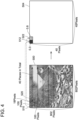
- FIG. 5 shows an example of the probability data 504 corresponding to the cancer cell. In FIG. 5 as well, pixels are whiter with the higher probability.
- the generation process as above is not limited to the CNN. In examples not within the scope of the claims it may be executed according to a support vector machine or a decision tree.
- the CPU 32 further uses the object data 44 representing the lymphocyte and generates probability data 506 (see FIG. 5 ) similar to the above. Further, the CPU 32 further uses object data (not shown) representing the normal epitheliocyte and generates probability data 508 similar to the above.
- the image analysis of the present embodiment differs from the conventional image processing in (1) of FIG. 3 in regard to a process in the first convolutional layer.
- the CPU 32 uses the reduced image data as the three pieces of channel data corresponding to the three channels of RGB as has been the case with the conventional image processing, however, the CPU 32 further executes the convolutional layer process using the probability data 504 as one piece of channel data corresponding to one channel.
- the CPU 32 further executes the convolutional layer process using the probability data 506 as one piece of channel data corresponding to one channel, and also the probability data 508 as one piece of channel data corresponding to one channel.
- the CPU 32 firstly reduces the target image data to generate the reduced image data similar to the conventional image processing, and executes respective processes of (1) to (5) of FIG. 6 .
- the CPU 32 executes the convolutional layer process by using not only the generated reduced image data but also the three pieces of probability data 504, 506, 508 as three pieces of channel data.
- Six-layer pattern data included in the pattern data 42 is used in the convolutional layer hereof.
- FIG. 6(A) shows an example of the six-layer pattern data.
- the six-layer pattern data includes one layer of data corresponding to the R values, one layer of data corresponding to the G values, one layer of data corresponding to the B values, one layer of data corresponding to a probability P1 that the cancer cell is present, one layer of data corresponding to a probability P2 that the lymphocyte is present, and one layer of data corresponding to a probability P3 that the normal epitheliocyte is present.
- Each of the six layers of data includes (3 ⁇ 3) pixels constituted of 3 pixels aligned along the lateral direction and 3 pixels aligned along the vertical direction. That is, the six-layer pattern data is constituted of (3 ⁇ 3 ⁇ 6) pixels.
- the CPU 32 specifies (3 ⁇ 3) pixels included in the reduced image data as a target pixel group and compares (3 ⁇ 3) R values included in this target pixel group with (3 ⁇ 3) R values included in the one layer corresponding to the R values in the three-layer pattern data. Similarly, the CPU 32 executes comparisons for the G values and the B values as well. Further, the CPU 32 specifies (3 ⁇ 3) pixels included in the probability data 504 corresponding to the cancer cell as a target pixel group and compares (3 ⁇ 3) values included in this target pixel group with (3 ⁇ 3) values included in the one layer of data corresponding to the probability P1 in the six-layer pattern data. Similarly, the CPU 32 executes comparisons for the probability data 506, 508 corresponding to the lymphocyte and the normal epitheliocyte as well.
- the CPU 32 uses the respective comparison results to calculate match rates between the target pixel groups and the six-layer pattern data.
- the CPU 32 generates a primary feature map 601 in which respectively specified match rates are described by sequentially specifying the target pixel groups from the reduced image data and the probability data 504, 506, 508 and sequentially specifying the match rates thereof.
- the primary feature map 601 includes (40 ⁇ 40) pixels constituted of 40 pixels aligned along the lateral direction and 40 pixels aligned along the vertical direction, and each pixel indicates the match rate.
- the CPU 32 executes the convolutional layer process for each of the plurality of pieces of six-layer pattern data and generates a plurality of primary feature maps 601 to 604 corresponding to the plurality of pieces of six-layer pattern data.
- the processes of (2) to (5) are same as those of (2) to (5) of FIG. 3 except that the plurality of primary feature maps 601 to 604 is used. That is, (2) the pooling layer process is executed for the plurality of primary feature maps 601 to 604 by which a plurality of reduced primary feature maps 611 to 614 is generated, and (3) the convolutional layer process is executed for the plurality of reduced primary feature maps 611 to 614 by which a plurality of secondary feature maps 621 to 626 is generated. Further, (4) the pooling layer process is executed for the plurality of secondary feature maps 621 to 626 by which a plurality of reduced secondary feature maps 631 to 636 is generated, and (5) a result of the image analysis is outputted.
- an analysis result with high analysis accuracy may be obtained by employing a configuration that uses target image data as three pieces of channel data corresponding to three channels without reducing the target image data.
- the target image data includes (802 ⁇ 802) pixels, and as such, a long period of time is required and a high memory volume is consumed in the convolutional layer process in (1) of FIG. 3(C) .
- each primary feature map generated by the convolutional layer process also includes (802 ⁇ 802) pixels
- each reduced primary feature map generated in the pooling layer in (2) of FIG. 3(C) also includes (401 ⁇ 401) pixels, by which a long period of time is required and a high memory volume is consumed also in the convolutional layer and the pooling layer process which take place thereafter.
- the image analysis device 10 uses the reduced image data as the three pieces of channel data corresponding to the three channels in executing the image analysis according to the CNN, so that the image analysis can be executed promptly.
- the image analysis device 10 uses the probability data 504 as the one piece of channel data corresponding to the one channel in addition to the reduced image data as the three pieces of channel data corresponding to the three channels. Due to this, the image analysis device 10 can improve analysis accuracy related to the image including the cancer cell in the image analysis using the reduced image data.
- the image analysis device 10 further uses the probability data 506 as the one piece of channel data corresponding to the one channel and also the probability data 508 as the one piece of channel data corresponding to the one channel. By doing so, the image analysis device 10 can further improve both analysis accuracy related to the image including the lymphocyte and analysis accuracy related to the image including the normal epitheliocyte in the image analysis using the reduced image data.
- Japanese Patent Application Publication Nos. 2004-286666 and 2010-281636 describe techniques related to image analysis.
- the art disclosed in the present embodiment (which the inventor calls the "component channel CNN (cc-CNN)") completely differs from such conventional techniques, and executes the CNN using the probability data 504 to 508 corresponding to the cancer cell and the like as the channel data. Due to this, prompting of the image analysis, suppression of memory consumption, and high analysis accuracy can be realized.
- the cancer cell and the lymphocyte are respectively an example of a "first object” and a "second object”.
- the lateral direction and the vertical direction are respectively an example of a "first direction” and a "second direction”.
- the (802 ⁇ 802) pixels in the target image data is an example of "(M ⁇ N) pixels" and the three channels of RGB are an example of "K channels”.
- the (40 ⁇ 40) partial images are an example of "(m ⁇ n) partial images”.
- the (40 ⁇ 40) pixels in the probability data are an example of "(m ⁇ n) pixels".
- the probability data 504 and the probability data 506 are respectively an example of "first probability data” and "second probability data”.
- the image analysis device 10 may execute the image analysis on images including other objects (such as a human or a tree).
- the image analysis device 10 stores a piece of object data representing a human and a piece of object data representing a tree as the pieces of object data 44.
- the image analysis device 10 generates a piece of probability data representing a probability that a human is present and a piece of probability data representing a probability that a tree is present based on the target image data.
- the image analysis device 10 executes the CNN using reduced image data obtained by reducing the target image data and the plurality of pieces of probability data that were respectively generated, by which the image analysis related to the human and the tree can be executed promptly and highly accurately. That is, in this variant, any one of the human and the tree is an example of the "first object" and the "first object” may not be a predetermined cell.
- the respective pixels constituting the target image data include the three values corresponding to the three channels of RGB.
- the respective pixels constituting the target image data may include only one value corresponding to one channel such as a luminance value.
- the respective pixels constituting the reduced image data also include only one value corresponding to the one channel.
- four-layer pattern data including one layer of data corresponding to the luminance value, the one layer of data corresponding to the probability P1 that the cancer cell is present, the one layer of data corresponding to the probability P2 that the lymphocyte is present, and the one layer of data corresponding to the probability P3 that the normal epitheliocyte is present is used. That is, in the present variant, the "K" is 1. In another variant, the "K" may be 2, or may be 4 or more.
- the probability data 506, 508 may not be used. That is, at least one probability data may be used. In the present variant, a "second generating unit" may be omitted. Further, in another variant, additional piece of probability data may be generated and the convolutional layer process in (1) of FIG. 6(C) may be executed with this additional piece of probability data being further be used as one piece of channel data. That is, a number of the probability data may be 3 or more.
- FIGS. 4 and 6 are realized by software (that is, the analysis program 38), however, at least one of these processes may be realized by hardware such as a logic circuit.
- 10 image analysis device
- 12 operation unit
- 14 display
- 16 input unit
- 30 controller
- 34 memory
- 36 OS program
- 38 analysis program
- 40 analysis data
- 42 pattern data
- 44 object data
- 101, 102, 103, 104 601, 602, 603, 604: primary feature map, 201, 202, 203, 204, 611, 612, 613, 614: reduced primary feature map, 301, 302, 303, 304, 305, 306, 621, 622, 623, 624, 625, 626: secondary feature map, 401, 402, 403, 404, 405, 406, 631, 632, 633, 634, 635, 636: reduced secondary feature map, 500: target image, 502: reduced image, 510, 520: partial image, 512, 522: pixel, 504, 506, 508: probability data
Landscapes
- Engineering & Computer Science (AREA)
- Health & Medical Sciences (AREA)
- Physics & Mathematics (AREA)
- General Health & Medical Sciences (AREA)
- General Physics & Mathematics (AREA)
- Life Sciences & Earth Sciences (AREA)
- Medical Informatics (AREA)
- Computer Vision & Pattern Recognition (AREA)
- Quality & Reliability (AREA)
- Radiology & Medical Imaging (AREA)
- Theoretical Computer Science (AREA)
- Nuclear Medicine, Radiotherapy & Molecular Imaging (AREA)
- Chemical & Material Sciences (AREA)
- Biomedical Technology (AREA)
- Molecular Biology (AREA)
- Urology & Nephrology (AREA)
- Hematology (AREA)
- Food Science & Technology (AREA)
- Medicinal Chemistry (AREA)
- Analytical Chemistry (AREA)
- Biochemistry (AREA)
- Immunology (AREA)
- Pathology (AREA)
- Image Analysis (AREA)
- Investigating Or Analysing Biological Materials (AREA)
Claims (6)
- Bildanalysevorrichtung (10) mit:einem Speicher, der zum Speichern von ersten Objektdaten, die ein erstes Objekt darstellen, ausgebildet ist;einer Erhalteeinheit, die zum Erhalten von Zielbilddaten, die ein Zielbild (500), das ein Analyseziel ist, darstellen, ausgebildet ist, wobei die Zielbilddaten (M×N) Pixel aufweisen, die aus M Pixel, die entlang der ersten Richtung ausgerichtet sind, und N Pixel, die entlang einer zweiten Richtung orthogonal zu der ersten Richtung ausgerichtet sind, gebildet werden, wobei M eine ganze Zahl größer oder gleich 3 ist und N eine ganze Zahl größer oder gleich 3 ist und jedes Pixel der (M×N) Pixel K Werte angibt, die K Kanälen entsprechen, wobei K eine ganze Zahl größer oder gleich 1 ist;einer Spezifiziereinheit, die zum Spezifizieren von (m×n) Teilbildern der Reihe nach durch Scannen der Zielbilddaten ausgebildet ist, wobei die (m×n) Teilbilder aus m Teilbildern, die entlang der ersten Richtung ausgerichtet sind, und n Teilbildern, die entlang der zweiten Richtung ausgerichtet sind, gebildet werden, wobei m eine ganze Zahl größer oder gleich 2 und kleiner als M ist und n eine ganze Zahl größer oder gleich 2 und kleiner als N ist;einer Erzeugungseinheit, die zum Erzeugen von L Stücken von zusätzlichen Kanaldaten, die erste Wahrscheinlichkeitsdaten (504) aufweisen, unter Verwendung der (m×n) Teilbilder und eines ersten faltenden neuronalen Netzes, das die ersten Objektdaten in dem Speicher verwendet, ausgebildet ist, wobei L eine ganze Zahl größer oder gleich 1 ist, wobei die ersten Wahrscheinlichkeitsdaten (504) (m×n) Pixel aufweisen, die aus m Pixel, die entlang der ersten Richtung ausgerichtet sind, und n Pixel, die entlang der zweiten Richtung ausgereichtet sind, gebildet werden, und wobei jedes Pixel der (m×n) Pixel, die in den ersten Wahrscheinlichkeitsdaten (504) enthalten sind, einen Wert in Bezug auf eine Wahrscheinlichkeit, dass ein Teilbild, das dem Pixel entspricht, das erste Objekt aufweist, angibt;einer Verringerungseinheit, die zum Verringern der Zielbilddaten zum Erzeugen von reduzierten Bilddaten ausgebildet ist, wobei die reduzierten Bilddaten (m×n) Pixel aufweisen, die aus m Pixel, die entlang der ersten Richtung ausgerichtet sind, und n Pixel, die entlang der zweiten Richtung ausgerichtet sind, gebildet werden, wobei (K+L) Stücke von Kanaldaten, die (K+L) Kanälen entsprechen, unter Verwendung der verringerten Bilddaten als K Stücke von Kanaldaten, die den K Kanälen entsprechen, und unter Verwendung der L Stücke von zusätzlichen Kanaldaten als L Stücke von Kanaldaten, die L zusätzlichen Kanälen entsprechen, erzeugt werden;einer Analyseeinheit, die zum Ausführen einer Bildanalyse gemäß einem zweiten faltenden neuronalen Netz unter Verwendung der (K+L) Stücke von Kanaldaten ausgebildet ist, wobeidie Bildanalyse Ausführen eines Faltungsschichtprozesses unter Verwendung der (K+L) Stücke von Kanaldaten, die den (K+L) Kanälen entsprechen, und von (K+L) Stücken von Musterdaten (42), die im Voraus bereitgestellt werden und den (K+L) Kanälen entsprechen, beinhaltet;jedes Stück der (K+L) Stücke von Musterdaten (42) (m'×n') Pixel aufweist, die aus m' Pixel, die entlang der ersten Richtung ausgerichtet sind, und n' Pixel, die entlang der zweiten Richtung ausgerichtet sind, gebildet werden, wobei m' eine ganze Zahl kleiner als m ist und n' eine ganze Zahl kleiner als n ist, undder Faltungsschichtprozess einen Prozess zum Ausführen, für jeden der (K+L) Kanäle, eines Vergleichs zwischen Werten einer Zielpixelgruppe in einem Stück von Kanaldaten, die dem Kanal entsprechen, und Werten eines Stücks der Musterdaten (42), die dem Kanal entsprechen, und Berechnen einer Übereinstimmungsrate zwischen der Zielpixelgruppe und den (K+L) Stücken von Musterdaten unter Verwendung der jeweiligen Vergleiche beinhaltet; undeiner Ausgabeeinheit, die zum Ausgeben eines Ergebnisses der Bildanalyse ausgebildet ist.
- Bildanalysevorrichtung (10) nach Anspruch 1, bei der
die K Kanäle drei Kanäle von RGB sind. - Bildanalysevorrichtung (10) nach Anspruch 1 oder 2, bei derder Speicher ferner zum Speichern von zweiten Objektdaten, die ein zweites Objekt, das sich von dem ersten Objekt unterscheidet, darstellen, ausgebildet ist,die Erzeugungseinheit ferner ausgebildet ist zum Erzeugen der L Stücke von zusätzlichen Kanaldaten, die ferner zweite Wahrscheinlichkeitsdaten (506) aufweisen, unter Verwendung der (m×n) Teilbilder und der zweiten Objektdaten in dem Speicher, wobei die zweiten Wahrscheinlichkeitsdaten (506) (m×n) Pixel aufweisen, die aus m Pixel, die entlang der ersten Richtung ausgerichtet sind, und n Pixel, die entlang der zweiten Richtung ausgerichtet sind, gebildet werden, und jedes Pixel der (m×n) Pixel, die in den zweiten Wahrscheinlichkeitsdaten (506) enthalten sind, einen Wert in Bezug auf eine Wahrscheinlichkeit, dass ein Teilbild, das dem Pixel entspricht, das zweite Objekt enthält, angibt, unddie (K+L) Stücke von Kanaldaten unter Verwendung der L Stücke von zusätzlichen Kanaldaten, die die ersten Wahrscheinlichkeitsdaten (504) und die zweiten Wahrscheinlichkeitsdaten (506) aufweisen, erzeugt werden.
- Bildanalysevorrichtung (10) nach einem der Ansprüche 1 bis 3, bei der das erste Objekt eine vorbestimmte Zelle ist.
- Computerprogramm mit Anweisungen, die bei einer Ausführung auf einem Computer einer Bildanalysevorrichtung (10) bewirken, dass der Computer der Bildanalysevorrichtung (10) fungiert als:eine Erhalteeinheit, die zum Erhalten von Zielbilddaten, die ein Zielbild (500), das ein Analyseziel ist, darstellen, ausgebildet ist, wobei die Zielbilddaten (M×N) Pixel aufweisen, die aus M Pixel, die entlang der ersten Richtung ausgerichtet sind, und N Pixel, die entlang einer zweiten Richtung orthogonal zu der ersten Richtung ausgerichtet sind, gebildet werden, wobei M eine ganze Zahl größer oder gleich 3 ist und N eine ganze Zahl größer oder gleich 3 ist und jedes Pixel der (M×N) Pixel K Werte angibt, die K Kanälen entsprechen, wobei K eine ganze Zahl größer oder gleich 1 ist;eine Spezifiziereinheit, die zum Spezifizieren von (m×n) Teilbildern der Reihe nach durch Scannen der Zielbilddaten ausgebildet ist, wobei die (m×n) Teilbilder aus m Teilbildern, die entlang der ersten Richtung ausgerichtet sind, und n Teilbildern, die entlang der zweiten Richtung ausgerichtet sind, gebildet werden, wobei m eine ganze Zahl größer oder gleich 2 und kleiner als M ist und n eine ganze Zahl größer oder gleich 2 und kleiner als N ist;eine Erzeugungseinheit, die zum Erzeugen von L Stücken von zusätzlichen Kanaldaten, die erste Wahrscheinlichkeitsdaten (504) aufweisen, unter Verwendung der (m×n) Teilbilder und eines ersten faltenden neuronalen Netzes, das die ersten Objektdaten in dem Speicher verwendet, ausgebildet ist, wobei L eine ganze Zahl größer oder gleich 1 ist, wobei die ersten Wahrscheinlichkeitsdaten (504) (m×n) Pixel aufweisen, die aus m Pixel, die entlang der ersten Richtung ausgerichtet sind, und n Pixel, die entlang der zweiten Richtung ausgereichtet sind, gebildet werden, und wobei jedes Pixel der (m×n) Pixel, die in den ersten Wahrscheinlichkeitsdaten (504) enthalten sind, einen Wert in Bezug auf eine Wahrscheinlichkeit, dass ein Teilbild, das dem Pixel entspricht, das erste Objekt aufweist, angibt;eine Verringerungseinheit, die zum Verringern der Zielbilddaten zum Erzeugen von reduzierten Bilddaten ausgebildet ist, wobei die reduzierten Bilddaten (m×n) Pixel aufweisen, die aus m Pixel, die entlang der ersten Richtung ausgerichtet sind, und n Pixel, die entlang der zweiten Richtung ausgerichtet sind, gebildet werden, wobei (K+L) Stücke von Kanaldaten, die (K+L) Kanälen entsprechen, unter Verwendung der verringerten Bilddaten als K Stücke von Kanaldaten, die den K Kanälen entsprechen, und unter Verwendung der L Stücke von zusätzlichen Kanaldaten als L Stücke von Kanaldaten, die L zusätzlichen Kanälen entsprechen, erzeugt werden;eine Analyseeinheit, die zum Ausführen einer Bildanalyse gemäß einem zweiten faltenden neuronalen Netz unter Verwendung der (K+L) Stücke von Kanaldaten ausgebildet ist, wobeidie Bildanalyse Ausführen eines Faltungsschichtprozesses unter Verwendung der (K+L) Stücke von Kanaldaten, die den (K+L) Kanälen entsprechen, und von (K+L) Stücken von Musterdaten (42), die im Voraus bereitgestellt werden und den (K+L) Kanälen entsprechen, beinhaltet;jedes Stück der (K+L) Stücke von Musterdaten (42) (m'×n') Pixel aufweist, die aus m' Pixel, die entlang der ersten Richtung ausgerichtet sind, und n' Pixel, die entlang der zweiten Richtung ausgerichtet sind, gebildet werden, wobei m' eine ganze Zahl kleiner als m ist und n' eine ganze Zahl kleiner als n ist, undder Faltungsschichtprozess einen Prozess zum Ausführen, für jeden der (K+L) Kanäle, eines Vergleichs zwischen Werten einer Zielpixelgruppe in einem Stück von Kanaldaten, die dem Kanal entsprechen, und Werten eines Stücks der Musterdaten (42), die dem Kanal entsprechen, und Berechnen einer Übereinstimmungsrate zwischen der Zielpixelgruppe und den (K+L) Stücken von Musterdaten unter Verwendung der jeweiligen Vergleiche beinhaltet; undeine Ausgabeeinheit, die zum Ausgeben eines Ergebnisses der Bildanalyse ausgebildet ist.
- Computerimplementiertes Verfahren zum Analysieren eines Bilds, mit folgenden Schritten:einem Erhalteschritt zum Erhalten von Zielbilddaten, die ein Zielbild (500), das ein Analyseziel ist, darstellen, wobei die Zielbilddaten (M×N) Pixel aufweisen, die aus M Pixel, die entlang der ersten Richtung ausgerichtet sind, und N Pixel, die entlang einer zweiten Richtung orthogonal zu der ersten Richtung ausgerichtet sind, gebildet werden, wobei M eine ganze Zahl größer oder gleich 3 ist und N eine ganze Zahl größer oder gleich 3 ist und jedes Pixel der (M×N) Pixel K Werte angibt, die K Kanälen entsprechen, wobei K eine ganze Zahl größer oder gleich 1 ist;einem Spezifizierschritt zum Spezifizieren von (m×n) Teilbildern der Reihe nach durch Scannen der Zielbilddaten, wobei die (m×n) Teilbilder aus m Teilbildern, die entlang der ersten Richtung ausgerichtet sind, und n Teilbildern, die entlang der zweiten Richtung ausgerichtet sind, gebildet werden, wobei m eine ganze Zahl größer oder gleich 2 und kleiner als M ist und n eine ganze Zahl größer oder gleich 2 und kleiner als N ist;einem Erzeugungsschritt zum Erzeugen von L Stücken von zusätzlichen Kanaldaten, die erste Wahrscheinlichkeitsdaten (504) aufweisen, unter Verwendung der (m×n) Teilbilder und eines ersten faltenden neuronalen Netzes, das die ersten Objektdaten in dem Speicher verwendet, wobei L eine ganze Zahl größer oder gleich 1 ist, wobei die ersten Wahrscheinlichkeitsdaten (504) (m×n) Pixel aufweisen, die aus m Pixel, die entlang der ersten Richtung ausgerichtet sind, und n Pixel, die entlang der zweiten Richtung ausgereichtet sind, gebildet werden, und wobei jedes Pixel der (m×n) Pixel, die in den ersten Wahrscheinlichkeitsdaten (504) enthalten sind, einen Wert in Bezug auf eine Wahrscheinlichkeit, dass ein Teilbild, das dem Pixel entspricht, das erste Objekt aufweist, angibt;einem Verringerungsschritt zum Verringern der Zielbilddaten zum Erzeugen von reduzierten Bilddaten, wobei die reduzierten Bilddaten (m×n) Pixel aufweisen, die aus m Pixel, die entlang der ersten Richtung ausgerichtet sind, und n Pixel, die entlang der zweiten Richtung ausgerichtet sind, gebildet werden, wobei (K+L) Stücke von Kanaldaten, die (K+L) Kanälen entsprechen, unter Verwendung der verringerten Bilddaten als K Stücke von Kanaldaten, die den K Kanälen entsprechen, und unter Verwendung der L Stücke von zusätzlichen Kanaldaten als L Stücke von Kanaldaten, die L zusätzlichen Kanälen entsprechen, erzeugt werden;einem Analyseschritt zum Ausführen einer Bildanalyse gemäß einem zweiten faltenden neuronalen Netz unter Verwendung der (K+L) Stücke von Kanaldaten, wobeidie Bildanalyse Ausführen eines Faltungsschichtprozesses unter Verwendung der (K+L) Stücke von Kanaldaten, die den (K+L) Kanälen entsprechen, und von (K+L) Stücken von Musterdaten (42), die im Voraus bereitgestellt werden und den (K+L) Kanälen entsprechen, beinhaltet;jedes Stück der (K+L) Stücke von Musterdaten (42) (m'×n') Pixel aufweist, die aus m' Pixel, die entlang der ersten Richtung ausgerichtet sind, und n' Pixel, die entlang der zweiten Richtung ausgerichtet sind, gebildet werden, wobei m' eine ganze Zahl kleiner als m ist und n' eine ganze Zahl kleiner als n ist, undder Faltungsschichtprozess einen Prozess zum Ausführen, für jeden der (K+L) Kanäle, eines Vergleichs zwischen Werten einer Zielpixelgruppe in einem Stück von Kanaldaten, die dem Kanal entsprechen, und Werten eines Stücks der Musterdaten (42), die dem Kanal entsprechen, und Berechnen einer Übereinstimmungsrate zwischen der Zielpixelgruppe und den (K+L) Stücken von Musterdaten unter Verwendung der jeweiligen Vergleiche beinhaltet; undeinem Ausgabeschritt zum Ausgeben eines Ergebnisses der Bildanalyse.
Applications Claiming Priority (1)
| Application Number | Priority Date | Filing Date | Title |
|---|---|---|---|
| PCT/JP2017/038404 WO2019082283A1 (ja) | 2017-10-24 | 2017-10-24 | 画像解析装置 |
Publications (3)
| Publication Number | Publication Date |
|---|---|
| EP3699863A1 EP3699863A1 (de) | 2020-08-26 |
| EP3699863A4 EP3699863A4 (de) | 2020-10-14 |
| EP3699863B1 true EP3699863B1 (de) | 2025-04-30 |
Family
ID=66247350
Family Applications (1)
| Application Number | Title | Priority Date | Filing Date |
|---|---|---|---|
| EP17929925.0A Active EP3699863B1 (de) | 2017-10-24 | 2017-10-24 | Bildinterpretationsvorrichtung |
Country Status (4)
| Country | Link |
|---|---|
| US (1) | US11321832B2 (de) |
| EP (1) | EP3699863B1 (de) |
| JP (1) | JP7106144B2 (de) |
| WO (1) | WO2019082283A1 (de) |
Families Citing this family (1)
| Publication number | Priority date | Publication date | Assignee | Title |
|---|---|---|---|---|
| EP3699863B1 (de) | 2017-10-24 | 2025-04-30 | Toru Nagasaka | Bildinterpretationsvorrichtung |
Family Cites Families (15)
| Publication number | Priority date | Publication date | Assignee | Title |
|---|---|---|---|---|
| JP2001059842A (ja) | 1999-08-25 | 2001-03-06 | Nec Corp | 病理診断装置 |
| JP2004286666A (ja) | 2003-03-24 | 2004-10-14 | Olympus Corp | 病理診断支援装置および病理診断支援プログラム |
| JP2004340738A (ja) | 2003-05-15 | 2004-12-02 | Sysmex Corp | 細胞分類装置とシステム及び細胞分類方法 |
| US8582860B2 (en) | 2008-07-03 | 2013-11-12 | Nec Laboratories America, Inc. | Signet ring cell detector and related methods |
| JP5387146B2 (ja) | 2009-06-03 | 2014-01-15 | 日本電気株式会社 | 病理組織画像解析装置、病理組織画像解析方法、病理組織画像解析プログラム |
| JP5538967B2 (ja) * | 2009-06-18 | 2014-07-02 | キヤノン株式会社 | 情報処理装置、情報処理方法、プログラム |
| JP2011176748A (ja) * | 2010-02-25 | 2011-09-08 | Sony Corp | 画像処理装置および方法、並びにプログラム |
| GB201015581D0 (en) * | 2010-09-17 | 2010-10-27 | Vib Vzw | Mutations in SPTLC2 gene associated with sensory neuropathy |
| JP2015095042A (ja) * | 2013-11-11 | 2015-05-18 | 独立行政法人科学技術振興機構 | 画像認識装置、画像認識方法、および、プログラム |
| JP2015232869A (ja) * | 2014-05-16 | 2015-12-24 | 株式会社リコー | 画像処理装置、画像処理方法及び画像処理プログラム |
| JP6488380B2 (ja) * | 2014-12-17 | 2019-03-20 | ノキア テクノロジーズ オーユー | ニューラルネットワークによるオブジェクト検出 |
| US10282663B2 (en) * | 2015-08-15 | 2019-05-07 | Salesforce.Com, Inc. | Three-dimensional (3D) convolution with 3D batch normalization |
| US9760807B2 (en) * | 2016-01-08 | 2017-09-12 | Siemens Healthcare Gmbh | Deep image-to-image network learning for medical image analysis |
| KR102419136B1 (ko) * | 2017-06-15 | 2022-07-08 | 삼성전자주식회사 | 다채널 특징맵을 이용하는 영상 처리 장치 및 방법 |
| EP3699863B1 (de) | 2017-10-24 | 2025-04-30 | Toru Nagasaka | Bildinterpretationsvorrichtung |
-
2017
- 2017-10-24 EP EP17929925.0A patent/EP3699863B1/de active Active
- 2017-10-24 JP JP2019549725A patent/JP7106144B2/ja active Active
- 2017-10-24 WO PCT/JP2017/038404 patent/WO2019082283A1/ja not_active Ceased
- 2017-10-24 US US16/757,988 patent/US11321832B2/en active Active
Non-Patent Citations (1)
| Title |
|---|
| ANONYMOUS: "OpenCV: Object Detection - "matchTemplate()" Function Documentation", 4 August 2017 (2017-08-04), XP055982890, Retrieved from the Internet <URL:https://docs.opencv.org/3.3.0/df/dfb/group__imgproc__object.html> [retrieved on 20221118] * |
Also Published As
| Publication number | Publication date |
|---|---|
| JPWO2019082283A1 (ja) | 2020-11-19 |
| EP3699863A1 (de) | 2020-08-26 |
| JP7106144B2 (ja) | 2022-07-26 |
| US11321832B2 (en) | 2022-05-03 |
| WO2019082283A1 (ja) | 2019-05-02 |
| EP3699863A4 (de) | 2020-10-14 |
| US20200342590A1 (en) | 2020-10-29 |
Similar Documents
| Publication | Publication Date | Title |
|---|---|---|
| US10268883B2 (en) | Form structure extraction network | |
| CN113792851B (zh) | 字体生成模型训练方法、字库建立方法、装置及设备 | |
| US8340433B2 (en) | Image processing apparatus, electronic medium, and image processing method | |
| KR102508860B1 (ko) | 이미지에서의 키 포인트 위치의 인식 방법, 장치, 전자기기 및 매체 | |
| EP3214579B1 (de) | Bildverarbeitungsvorrichtung, zeichenerkennungsvorrichtung, bildverarbeitungsverfahren, und programm | |
| EP4276754B1 (de) | Bildverarbeitungsverfahren und -vorrichtung, vorrichtung, speichermedium und computerprogrammprodukt | |
| US11792514B2 (en) | Method and apparatus for stabilizing image, roadside device and cloud control platform | |
| CN111724396A (zh) | 图像分割方法及装置、计算机可读存储介质、电子设备 | |
| US12217472B2 (en) | Segmenting and removing objects from visual media items | |
| CN114241496B (zh) | 用于阅读任务的预训练模型训练方法、装置及其电子设备 | |
| CN112734900B (zh) | 阴影贴图的烘焙方法、装置、设备及计算机可读存储介质 | |
| US12347061B2 (en) | Splitting and scaling images for input to a model and method, medium, and device therefor | |
| JP2024150733A (ja) | 大規模言語モデルに用いられるタスク実行方法、装置、機器及び記憶媒体 | |
| CN110619597A (zh) | 一种半透明水印去除方法、装置、电子设备及存储介质 | |
| US11257212B2 (en) | Image analysis device | |
| EP3699863B1 (de) | Bildinterpretationsvorrichtung | |
| CN111985471B (zh) | 一种车牌定位方法、装置及存储介质 | |
| CN113763496A (zh) | 图像着色的方法、装置及计算机可读存储介质 | |
| CN114841906B (zh) | 一种图像合成方法、装置、电子设备和存储介质 | |
| CN116012883B (zh) | 一种图像生成模型的训练方法、图像生成方法及装置 | |
| CN118587637A (zh) | 一种基于智能算法的复合烟感低误报方法 | |
| CN117315758A (zh) | 面部表情的检测方法、装置、电子设备及存储介质 | |
| CN118069858A (zh) | 一种知识图谱可视化方法、装置、电子设备及存储介质 | |
| US20240320957A1 (en) | Information processing apparatus, information processing method, and non-transitory computer-readable medium | |
| CN117421651A (zh) | 电弧故障识别方法和装置 |
Legal Events
| Date | Code | Title | Description |
|---|---|---|---|
| STAA | Information on the status of an ep patent application or granted ep patent |
Free format text: STATUS: THE INTERNATIONAL PUBLICATION HAS BEEN MADE |
|
| PUAI | Public reference made under article 153(3) epc to a published international application that has entered the european phase |
Free format text: ORIGINAL CODE: 0009012 |
|
| STAA | Information on the status of an ep patent application or granted ep patent |
Free format text: STATUS: REQUEST FOR EXAMINATION WAS MADE |
|
| 17P | Request for examination filed |
Effective date: 20200518 |
|
| AK | Designated contracting states |
Kind code of ref document: A1 Designated state(s): AL AT BE BG CH CY CZ DE DK EE ES FI FR GB GR HR HU IE IS IT LI LT LU LV MC MK MT NL NO PL PT RO RS SE SI SK SM TR |
|
| AX | Request for extension of the european patent |
Extension state: BA ME |
|
| A4 | Supplementary search report drawn up and despatched |
Effective date: 20200911 |
|
| RIC1 | Information provided on ipc code assigned before grant |
Ipc: G01N 33/48 20060101ALI20200907BHEP Ipc: G06T 7/00 20170101AFI20200907BHEP |
|
| DAV | Request for validation of the european patent (deleted) | ||
| DAX | Request for extension of the european patent (deleted) | ||
| STAA | Information on the status of an ep patent application or granted ep patent |
Free format text: STATUS: EXAMINATION IS IN PROGRESS |
|
| 17Q | First examination report despatched |
Effective date: 20221201 |
|
| GRAP | Despatch of communication of intention to grant a patent |
Free format text: ORIGINAL CODE: EPIDOSNIGR1 |
|
| STAA | Information on the status of an ep patent application or granted ep patent |
Free format text: STATUS: GRANT OF PATENT IS INTENDED |
|
| INTG | Intention to grant announced |
Effective date: 20250204 |
|
| GRAS | Grant fee paid |
Free format text: ORIGINAL CODE: EPIDOSNIGR3 |
|
| GRAA | (expected) grant |
Free format text: ORIGINAL CODE: 0009210 |
|
| STAA | Information on the status of an ep patent application or granted ep patent |
Free format text: STATUS: THE PATENT HAS BEEN GRANTED |
|
| AK | Designated contracting states |
Kind code of ref document: B1 Designated state(s): AL AT BE BG CH CY CZ DE DK EE ES FI FR GB GR HR HU IE IS IT LI LT LU LV MC MK MT NL NO PL PT RO RS SE SI SK SM TR |
|
| REG | Reference to a national code |
Ref country code: CH Ref legal event code: EP Ref country code: GB Ref legal event code: FG4D |
|
| REG | Reference to a national code |
Ref country code: IE Ref legal event code: FG4D |
|
| REG | Reference to a national code |
Ref country code: DE Ref legal event code: R096 Ref document number: 602017089259 Country of ref document: DE |
|
| REG | Reference to a national code |
Ref country code: NL Ref legal event code: MP Effective date: 20250430 |
|
| REG | Reference to a national code |
Ref country code: AT Ref legal event code: MK05 Ref document number: 1790766 Country of ref document: AT Kind code of ref document: T Effective date: 20250430 |
|
| PG25 | Lapsed in a contracting state [announced via postgrant information from national office to epo] |
Ref country code: FI Free format text: LAPSE BECAUSE OF FAILURE TO SUBMIT A TRANSLATION OF THE DESCRIPTION OR TO PAY THE FEE WITHIN THE PRESCRIBED TIME-LIMIT Effective date: 20250430 Ref country code: PT Free format text: LAPSE BECAUSE OF FAILURE TO SUBMIT A TRANSLATION OF THE DESCRIPTION OR TO PAY THE FEE WITHIN THE PRESCRIBED TIME-LIMIT Effective date: 20250901 Ref country code: ES Free format text: LAPSE BECAUSE OF FAILURE TO SUBMIT A TRANSLATION OF THE DESCRIPTION OR TO PAY THE FEE WITHIN THE PRESCRIBED TIME-LIMIT Effective date: 20250430 |
|
| REG | Reference to a national code |
Ref country code: LT Ref legal event code: MG9D |
|
| PG25 | Lapsed in a contracting state [announced via postgrant information from national office to epo] |
Ref country code: NO Free format text: LAPSE BECAUSE OF FAILURE TO SUBMIT A TRANSLATION OF THE DESCRIPTION OR TO PAY THE FEE WITHIN THE PRESCRIBED TIME-LIMIT Effective date: 20250730 Ref country code: GR Free format text: LAPSE BECAUSE OF FAILURE TO SUBMIT A TRANSLATION OF THE DESCRIPTION OR TO PAY THE FEE WITHIN THE PRESCRIBED TIME-LIMIT Effective date: 20250731 |
|
| PG25 | Lapsed in a contracting state [announced via postgrant information from national office to epo] |
Ref country code: PL Free format text: LAPSE BECAUSE OF FAILURE TO SUBMIT A TRANSLATION OF THE DESCRIPTION OR TO PAY THE FEE WITHIN THE PRESCRIBED TIME-LIMIT Effective date: 20250430 Ref country code: NL Free format text: LAPSE BECAUSE OF FAILURE TO SUBMIT A TRANSLATION OF THE DESCRIPTION OR TO PAY THE FEE WITHIN THE PRESCRIBED TIME-LIMIT Effective date: 20250430 |
|
| PG25 | Lapsed in a contracting state [announced via postgrant information from national office to epo] |
Ref country code: BG Free format text: LAPSE BECAUSE OF FAILURE TO SUBMIT A TRANSLATION OF THE DESCRIPTION OR TO PAY THE FEE WITHIN THE PRESCRIBED TIME-LIMIT Effective date: 20250430 |
|
| PG25 | Lapsed in a contracting state [announced via postgrant information from national office to epo] |
Ref country code: HR Free format text: LAPSE BECAUSE OF FAILURE TO SUBMIT A TRANSLATION OF THE DESCRIPTION OR TO PAY THE FEE WITHIN THE PRESCRIBED TIME-LIMIT Effective date: 20250430 |
|
| PG25 | Lapsed in a contracting state [announced via postgrant information from national office to epo] |
Ref country code: AT Free format text: LAPSE BECAUSE OF FAILURE TO SUBMIT A TRANSLATION OF THE DESCRIPTION OR TO PAY THE FEE WITHIN THE PRESCRIBED TIME-LIMIT Effective date: 20250430 |
|
| PG25 | Lapsed in a contracting state [announced via postgrant information from national office to epo] |
Ref country code: RS Free format text: LAPSE BECAUSE OF FAILURE TO SUBMIT A TRANSLATION OF THE DESCRIPTION OR TO PAY THE FEE WITHIN THE PRESCRIBED TIME-LIMIT Effective date: 20250731 |
|
| PG25 | Lapsed in a contracting state [announced via postgrant information from national office to epo] |
Ref country code: IS Free format text: LAPSE BECAUSE OF FAILURE TO SUBMIT A TRANSLATION OF THE DESCRIPTION OR TO PAY THE FEE WITHIN THE PRESCRIBED TIME-LIMIT Effective date: 20250830 |
|
| PG25 | Lapsed in a contracting state [announced via postgrant information from national office to epo] |
Ref country code: LV Free format text: LAPSE BECAUSE OF FAILURE TO SUBMIT A TRANSLATION OF THE DESCRIPTION OR TO PAY THE FEE WITHIN THE PRESCRIBED TIME-LIMIT Effective date: 20250430 |
|
| PGFP | Annual fee paid to national office [announced via postgrant information from national office to epo] |
Ref country code: DE Payment date: 20251020 Year of fee payment: 9 |
|
| PGFP | Annual fee paid to national office [announced via postgrant information from national office to epo] |
Ref country code: GB Payment date: 20251024 Year of fee payment: 9 |
|
| PG25 | Lapsed in a contracting state [announced via postgrant information from national office to epo] |
Ref country code: DK Free format text: LAPSE BECAUSE OF FAILURE TO SUBMIT A TRANSLATION OF THE DESCRIPTION OR TO PAY THE FEE WITHIN THE PRESCRIBED TIME-LIMIT Effective date: 20250430 Ref country code: SM Free format text: LAPSE BECAUSE OF FAILURE TO SUBMIT A TRANSLATION OF THE DESCRIPTION OR TO PAY THE FEE WITHIN THE PRESCRIBED TIME-LIMIT Effective date: 20250430 |
|
| PG25 | Lapsed in a contracting state [announced via postgrant information from national office to epo] |
Ref country code: CZ Free format text: LAPSE BECAUSE OF FAILURE TO SUBMIT A TRANSLATION OF THE DESCRIPTION OR TO PAY THE FEE WITHIN THE PRESCRIBED TIME-LIMIT Effective date: 20250430 |
|
| PG25 | Lapsed in a contracting state [announced via postgrant information from national office to epo] |
Ref country code: EE Free format text: LAPSE BECAUSE OF FAILURE TO SUBMIT A TRANSLATION OF THE DESCRIPTION OR TO PAY THE FEE WITHIN THE PRESCRIBED TIME-LIMIT Effective date: 20250430 |
|
| PG25 | Lapsed in a contracting state [announced via postgrant information from national office to epo] |
Ref country code: SK Free format text: LAPSE BECAUSE OF FAILURE TO SUBMIT A TRANSLATION OF THE DESCRIPTION OR TO PAY THE FEE WITHIN THE PRESCRIBED TIME-LIMIT Effective date: 20250430 Ref country code: RO Free format text: LAPSE BECAUSE OF FAILURE TO SUBMIT A TRANSLATION OF THE DESCRIPTION OR TO PAY THE FEE WITHIN THE PRESCRIBED TIME-LIMIT Effective date: 20250430 |
|
| PG25 | Lapsed in a contracting state [announced via postgrant information from national office to epo] |
Ref country code: IT Free format text: LAPSE BECAUSE OF FAILURE TO SUBMIT A TRANSLATION OF THE DESCRIPTION OR TO PAY THE FEE WITHIN THE PRESCRIBED TIME-LIMIT Effective date: 20250430 |
|
| REG | Reference to a national code |
Ref country code: DE Ref legal event code: R097 Ref document number: 602017089259 Country of ref document: DE |
|
| PLBE | No opposition filed within time limit |
Free format text: ORIGINAL CODE: 0009261 |
|
| STAA | Information on the status of an ep patent application or granted ep patent |
Free format text: STATUS: NO OPPOSITION FILED WITHIN TIME LIMIT |
|
| REG | Reference to a national code |
Ref country code: CH Ref legal event code: L10 Free format text: ST27 STATUS EVENT CODE: U-0-0-L10-L00 (AS PROVIDED BY THE NATIONAL OFFICE) Effective date: 20260311 |
|
| 26N | No opposition filed |
Effective date: 20260202 |