EP3699892A1 - Flexible abdeckplatte, flexible anzeigevorrichtung und flexibles endgerät - Google Patents
Flexible abdeckplatte, flexible anzeigevorrichtung und flexibles endgerät Download PDFInfo
- Publication number
- EP3699892A1 EP3699892A1 EP18879188.3A EP18879188A EP3699892A1 EP 3699892 A1 EP3699892 A1 EP 3699892A1 EP 18879188 A EP18879188 A EP 18879188A EP 3699892 A1 EP3699892 A1 EP 3699892A1
- Authority
- EP
- European Patent Office
- Prior art keywords
- layer
- cover
- flexible
- plate
- cover plate
- Prior art date
- Legal status (The legal status is an assumption and is not a legal conclusion. Google has not performed a legal analysis and makes no representation as to the accuracy of the status listed.)
- Granted
Links
Images


Classifications
-
- G—PHYSICS
- G06—COMPUTING OR CALCULATING; COUNTING
- G06F—ELECTRIC DIGITAL DATA PROCESSING
- G06F1/00—Details not covered by groups G06F3/00 - G06F13/00 and G06F21/00
- G06F1/16—Constructional details or arrangements
- G06F1/1613—Constructional details or arrangements for portable computers
- G06F1/1633—Constructional details or arrangements of portable computers not specific to the type of enclosures covered by groups G06F1/1615 - G06F1/1626
- G06F1/1637—Details related to the display arrangement, including those related to the mounting of the display in the housing
- G06F1/1652—Details related to the display arrangement, including those related to the mounting of the display in the housing the display being flexible, e.g. mimicking a sheet of paper, or rollable
-
- C—CHEMISTRY; METALLURGY
- C09—DYES; PAINTS; POLISHES; NATURAL RESINS; ADHESIVES; COMPOSITIONS NOT OTHERWISE PROVIDED FOR; APPLICATIONS OF MATERIALS NOT OTHERWISE PROVIDED FOR
- C09J—ADHESIVES; NON-MECHANICAL ASPECTS OF ADHESIVE PROCESSES IN GENERAL; ADHESIVE PROCESSES NOT PROVIDED FOR ELSEWHERE; USE OF MATERIALS AS ADHESIVES
- C09J7/00—Adhesives in the form of films or foils
-
- G—PHYSICS
- G06—COMPUTING OR CALCULATING; COUNTING
- G06F—ELECTRIC DIGITAL DATA PROCESSING
- G06F1/00—Details not covered by groups G06F3/00 - G06F13/00 and G06F21/00
- G06F1/16—Constructional details or arrangements
- G06F1/1613—Constructional details or arrangements for portable computers
- G06F1/1633—Constructional details or arrangements of portable computers not specific to the type of enclosures covered by groups G06F1/1615 - G06F1/1626
- G06F1/1656—Details related to functional adaptations of the enclosure, e.g. to provide protection against EMI, shock, water, or to host detachable peripherals like a mouse or removable expansions units like PCMCIA cards, or to provide access to internal components for maintenance or to removable storage supports like CDs or DVDs, or to mechanically mount accessories
-
- G—PHYSICS
- G09—EDUCATION; CRYPTOGRAPHY; DISPLAY; ADVERTISING; SEALS
- G09F—DISPLAYING; ADVERTISING; SIGNS; LABELS OR NAME-PLATES; SEALS
- G09F9/00—Indicating arrangements for variable information in which the information is built-up on a support by selection or combination of individual elements
- G09F9/30—Indicating arrangements for variable information in which the information is built-up on a support by selection or combination of individual elements in which the desired character or characters are formed by combining individual elements
-
- G—PHYSICS
- G09—EDUCATION; CRYPTOGRAPHY; DISPLAY; ADVERTISING; SEALS
- G09F—DISPLAYING; ADVERTISING; SIGNS; LABELS OR NAME-PLATES; SEALS
- G09F9/00—Indicating arrangements for variable information in which the information is built-up on a support by selection or combination of individual elements
- G09F9/30—Indicating arrangements for variable information in which the information is built-up on a support by selection or combination of individual elements in which the desired character or characters are formed by combining individual elements
- G09F9/301—Indicating arrangements for variable information in which the information is built-up on a support by selection or combination of individual elements in which the desired character or characters are formed by combining individual elements flexible foldable or roll-able electronic displays, e.g. thin LCD, OLED
-
- H—ELECTRICITY
- H05—ELECTRIC TECHNIQUES NOT OTHERWISE PROVIDED FOR
- H05K—PRINTED CIRCUITS; CASINGS OR CONSTRUCTIONAL DETAILS OF ELECTRIC APPARATUS; MANUFACTURE OF ASSEMBLAGES OF ELECTRICAL COMPONENTS
- H05K5/00—Casings, cabinets or drawers for electric apparatus
- H05K5/02—Details
- H05K5/03—Covers
-
- H—ELECTRICITY
- H05—ELECTRIC TECHNIQUES NOT OTHERWISE PROVIDED FOR
- H05K—PRINTED CIRCUITS; CASINGS OR CONSTRUCTIONAL DETAILS OF ELECTRIC APPARATUS; MANUFACTURE OF ASSEMBLAGES OF ELECTRICAL COMPONENTS
- H05K5/00—Casings, cabinets or drawers for electric apparatus
- H05K5/06—Hermetically-sealed casings
-
- G—PHYSICS
- G06—COMPUTING OR CALCULATING; COUNTING
- G06F—ELECTRIC DIGITAL DATA PROCESSING
- G06F2203/00—Indexing scheme relating to G06F3/00 - G06F3/048
- G06F2203/041—Indexing scheme relating to G06F3/041 - G06F3/045
- G06F2203/04102—Flexible digitiser, i.e. constructional details for allowing the whole digitising part of a device to be flexed or rolled like a sheet of paper
Definitions
- the present invention relates to the field of display technologies, and in particular, to a flexible cover plate, a flexible display apparatus, and a flexible terminal product.
- screens of intelligent terminal products such as a mobile phone and a tablet computer
- a screen of the mobile phone develops from a large screen to a small screen, from a straight screen to a curved screen, and to a bezelless screen and a foldable screen.
- the foldable screen is an important technical direction for development of the intelligent terminal product in future.
- a display screen is required to feature a repeated bending capability, without affecting a display function of the display screen due to bending.
- the display screen with the function may be a flexible display screen.
- a surface of an existing flexible module (the flexible module includes the foregoing flexible display screen, where the flexible display screen may also be a display layer) included in the intelligent terminal product has low hardness and weak strength due to a used material.
- a cover plate is required for protection. Therefore, the cover plate also needs to feature sufficient rigidity and the repeated bending capability.
- a material with good heat resistance and good light transmission is used as a base material of the flexible cover plate, and when a thickness of the material used as the base material can be reduced to a given extent, the flexible cover plate may have the repeated bending capability.
- a polyimide (English full name: Polyimide, PI for short) thin film is used as the base material of the flexible cover plate.
- a thickness of the PI thin film is less than 0.1 mm, and therefore the PI thin film has a good repeated bending capability.
- the thickness of the PI thin film is less than 0.1 m, the PI thin film cannot well protect the flexible module of the intelligent terminal product. In other words, the flexible cover plate does not have sufficient rigidity.
- Embodiments of this application provide a flexible cover plate, a flexible display apparatus, and a flexible terminal product, to make the flexible cover plate feature a repeated bending capability and sufficient rigidity.
- a first aspect of this application provides a flexible cover plate, including a first cover-plate layer, a second cover-plate layer, and a flow layer that is enclosed between the first cover-plate layer and the second cover-plate layer by using a transparent sealing material.
- the flow layer includes fluid capable of flowing, the first cover-plate layer and the second cover-plate layer each have a thickness ranging from 0.05 mm to 0.5 mm, and the flow layer has a thickness ranging from 0.1 mm to 0.2 mm.
- At least one first support bump is attached to an inner side of the first cover-plate layer, where the first support bump has a height ranging from 0.05 mm to 0.1 mm, and the inner side of the first cover-plate layer is a side that is of the first cover-plate layer and that is in direct contact with the flow layer.
- At least one second support bump is attached to an inner side of the second cover-plate layer, where the second support bump has a height ranging from 0.05 mm to 0.1 mm, and the inner side of the second cover-plate layer is a side that is of the second cover-plate layer and that is in direct contact with the flow layer.
- the flexible cover plate includes the first cover-plate layer, the second cover-plate layer, and the flow layer.
- the flexible cover plate When the flexible cover plate is bent, the fluid in the flow layer that is sealed between the first cover-plate layer and the second cover-plate layer flows toward two sides of the flexible cover plate, to reduce a thickness at a bent part, so that the first cover-plate layer and the second cover-plate layer are bent less and stretched less, thereby avoiding problems such as cracks and deformations that are caused when the first cover-plate layer and the second cover-plate layer are bent. Therefore, the flexible cover plate is enabled with a repeated bending capability.
- the flow layer may further have an impact buffer function, to avoid damage to a flexible module of a terminal product to some extent, and increase rigidity of the flexible cover plate.
- a first support bump and a second support bump are respectively disposed in an inner side of the first cover-plate layer and an inner side of the second cover-plate layer of the flexible cover plate, and the first support bump and the second support bump can provide a support function, thereby further ensuring overall rigidity of the flexible cover plate.
- the flow layer in addition to the fluid capable of flowing, may further include a transparent nano-glass material, where a percentage of a filling volume of the transparent nano-glass material to a filling volume of the fluid is from 10% to 50%.
- the transparent nano-glass material that accounts for a specific volume ratio of the filling volume of the fluid is added to the flow layer, so that the flow layer is gel-like.
- the flexible cover plate is bent, flow resistance of the fluid in the flow layer is increased to some extent, thereby avoiding problems such as cracks and deformations at a bent part in case of large bending force.
- the flow layer can effectively absorb energy, thereby effectively reducing impact against the flexible module.
- a material of the first cover-plate layer and the second cover-plate layer may be an inorganic material or an organic material.
- the first cover-plate layer and the second cover-plate layer may include a PI thin film or glass, where the PI thin film or glass is commonly used in a current terminal product.
- the first implementation of the first aspect of this application, or the second implementation of the first aspect of this application, in a third implementation of the first aspect of this application when there are at least two first support bumps attached to the inner side of the first cover-plate layer and at least two second support bumps attached to the inner side of the second cover-plate layer, the first support bumps are evenly attached to the inner side of the first cover-plate layer, and the second support bumps are also evenly attached to the inner side of the second cover-plate layer.
- the first support bumps and the second support bumps are respectively evenly attached to the inner side of the first cover-plate layer and the inner side of the second cover-plate layer. Therefore, regardless of a part at which the flexible cover plate is bent, the overall rigidity of the flexible cover plate can be ensured maximally.
- the first support bump and the second support bump each may be attached in the following manner: bonding, mold pressing, or coating.
- a plurality of attaching manners of the first support bump and a plurality of attaching manners of the second support bump are provided. This provides diversity in implementations and flexibility.
- the first support bump and the second support bump may include transparent resin.
- first support bump and the second support bump there may be various shapes of the first support bump and various shapes of the second support bump, and the shapes may be different from each other.
- the first support bump and the second support bump may be in the following shape: a cone, a tetrahedron, a hemisphere, or a cuboid.
- a plurality of shapes of the first support bump and the second support bump are provided, and this is flexible.
- the flow layer of the flexible cover plate may include OCA optical adhesive or UV adhesive.
- the transparent sealing material that is used to seal the flow layer between the first cover-plate layer and the second cover-plate layer may include polycarbonate, acrylic, or glass.
- a second aspect of the embodiments of this application provides a flexible display apparatus.
- the flexible display apparatus includes a flexible cover plate and a display layer.
- the flexible cover plate is bonded to the display layer, and the flexible cover plate is the flexible cover plate according to any one of the foregoing first aspect of this application, or the first implementation of the foregoing first aspect of this application to the eighth implementation of the foregoing first aspect of this application.
- the display layer is a display layer with a touch function, and can implement a function of a touch panel.
- the flexible display apparatus may further include a touch panel, and the flexible cover plate, the touch panel, and the display layer are sequentially bonded.
- the display layer may include an OLED display layer or an LCD display layer.
- a third aspect of the embodiments of this application provides a flexible terminal product.
- the flexible terminal product includes a flexible display apparatus and a foldable mechanism.
- the flexible display apparatus is bonded to the foldable mechanism.
- the flexible display apparatus is the flexible display apparatus according to the foregoing second aspect of this application or the first implementation of the foregoing second aspect of this application.
- the foldable mechanism is foldable and may include a housing, a PCB, a chip, and the like.
- the flexible cover plate includes the first cover-plate layer, the second cover-plate layer, and the flow layer that is sandwiched between the first cover-plate layer and the second cover-plate layer.
- the flow layer includes the fluid capable of flowing.
- the flow layer may further have the impact buffer function, thereby avoiding the damage to the flexible module of the terminal product to some extent, and increasing the rigidity of the flexible cover plate.
- the first support bump and the second support bump are respectively disposed in the inner side of the first cover-plate layer and the inner side of the second cover-plate layer of the flexible cover plate, and the first support bump and the second support bump can provide the support function, thereby further ensuring the overall rigidity of the flexible cover plate.
- Embodiments of this application provide a flexible cover plate, a flexible display apparatus, and a flexible terminal product, to make the flexible cover plate feature a repeated bending capability and sufficient rigidity.
- FIG. 1 shows a foldable mobile phone.
- a left side of FIG. 1 is an unfolded state of the mobile phone, and a right side of FIG. 1 is a folded state of the mobile phone.
- a structure of a foldable flexible terminal product may be divided into two parts as required: a flexible cover plate and a flexible module (that is, a part of an intelligent terminal product other than the flexible cover plate is referred to as the flexible module). Both the flexible cover plate and the flexible module are foldable, so that the entire flexible terminal product is bendable or foldable.
- a flexible module 201 may include a display layer 2002 and a foldable mechanism 2003.
- the foldable mechanism 2003 may specifically include components (including but not limited to a housing, a PCB, and a chip) that implement all functions of a flexible terminal product.
- a flexible cover plate 2001 and the display layer 2002 further constitute a flexible display apparatus 202 in this embodiment of this application.
- the flexible cover plate 2001 and the display layer 2002 are bonded to each other.
- the display layer 2002 shown in FIG. 2 is a display layer with a touch function, and can implement a function of a touch panel.
- the touch panel is embedded between a color filter substrate and a polarizer of the display layer by using an on-cell technology or an in-cell technology. If the display layer does not have the touch function, a touch panel is required between the flexible cover plate and the display layer.
- a touch panel 3002 is further sandwiched between a flexible cover plate 3001 and a display layer 3003 without a touch function.
- the flexible cover plate 3001, the touch panel 3002, and the display layer 3003 are sequentially bonded to each other.
- a current common method is to add a flexible cover plate to the flexible module to protect the flexible module.
- the flexible cover plate needs to feature sufficient rigidity and a repeated bending capability.
- the flexible cover plate is too thin to have sufficient rigidity, incapable of providing sufficient protection for the flexible module of the flexible terminal product.
- the flexible cover plate if the flexible cover plate is thick enough to provide sufficient protection for the flexible module, the flexible cover plate lacks a bending capability or the repeated bending capability due to an increase in thickness.
- a flexible cover plate provided in an embodiment of this application includes: a first cover-plate layer 11, a second cover-plate layer 12, and a flow layer 13.
- the flow layer 13 includes fluid capable of flowing.
- the flow layer 13 is enclosed between the first cover-plate layer 11 and the second cover-plate layer 12 by using a transparent sealing material 14.
- the transparent sealing material 14 may be polycarbonate, acrylic, or glass, and this is not specifically limited herein.
- the first cover-plate layer 11 and the second cover-plate layer 12 each have a thickness ranging from 0.05 mm to 0.5 mm, and the flow layer 13 has a thickness ranging from 0.1 mm to 0.2 mm.
- At least one first support bump 15 is attached to an inner side of the first cover-plate layer 11, where the first support bump 15 has a height ranging from 0.05 mm to 0.1 mm, and the inner side of the first cover-plate layer 11 is a side that is of the first cover-plate layer 11 and that is in direct contact with the flow layer 13.
- At least one second support bump 16 is attached to an inner side of the second cover-plate layer 12, where the second support bump 16 has a height ranging from 0.05 mm to 0.1 mm, and the inner side of the second cover-plate layer 12 is a side that is of the second cover-plate layer 12 and that is in direct contact with the flow layer 13.
- the first cover-plate layer 11 and the second cover-plate layer 12 each have the thickness that is limited to ranging from 0.05 mm to 0.5 mm, so that the first cover-plate layer 11 and the second cover-plate layer 12 can have a repeated bending capability. If values of the thicknesses are too large, the cover-plate layers are hard to be bent or does not have a bending capability.
- the flow layer 13 is configured to enable the flexible cover plate to feature the repeated bending capability, and further increase rigidity of the flexible cover plate.
- the flow layer 13 may further include a transparent nano-glass material 17, where a percentage of a filling volume of the transparent nano-glass material to a filling volume of the fluid in the flow layer 13 ranges from 10% to 50%.
- the transparent nano-glass material that accounts for a specific volume ratio of the filling volume of the fluid is added to the flow layer, so that the flow layer is gel-like.
- the transparent nano-glass material 17 in the flow layer 13, and when the flexible cover plate is bent, the transparent nano-glass material 17 also flows toward the two sides of the flexible cover plate), to reduce a thickness at a bent part, so that the first cover-plate layer 11 and the second cover-plate layer 12 are bent less and stretched less, thereby avoiding the problems such as cracks and deformations that are caused when the first cover-plate layer 11 and the second cover-plate layer 12 are bent. Therefore, the flexible cover plate is enabled with the repeated bending capability.
- the flow layer 13 may further have an impact buffer function, to avoid damage to a flexible module of a terminal product to some extent, and increase rigidity of the flexible cover plate.
- the fluid in the flow layer 13 flows back from the two sides of the flexible cover plate, so that the flexible cover plate restores to be in a flat state.
- the fluid in the flow layer 13 of the flexible cover plate may be OCA optical adhesive or UV adhesive. This is not specifically limited herein.
- first support bumps 15 or second support bumps 16 may be respectively evenly attached to an inner side of the first cover-plate layer 11 and an inner side of the second cover-plate layer 11.
- a spacing between the first support bumps 15 and a spacing between the second support bumps 16 may not be specified.
- the first support bumps 15 and the second support bumps 16 are respectively randomly attached to the inner side of the first cover-plate layer 11 or the inner side of the second cover-plate layer 11. This is not specifically limited herein.
- a spacing between the first support bumps 15 or a spacing between the second support bumps 16 at a part at which the flexible cover plate is frequently bent is relatively small, to ensure that the flexible cover plate is not easy to deform at the part at which the flexible cover plate is frequently bent, thereby increasing rigidity.
- the flow layer 13 in FIG. 6 may include a transparent nano-glass filler, which is not shown in FIG.
- a spacing between the first support bumps 15 that are close to the middle part of the first cover-plate layer 11 and a spacing between the second support bumps 16 that are close to the middle part of the second cover-plate layer 12 are smaller than spacings at other parts, thereby ensuring rigidity at the frequently bent part.
- the first support bump 15 or the second support bump 16 should also be disposed at a part at which the flexible cover plate is frequently bent. As shown in FIG. 7 (the flow layer 13 in FIG. 7 may include the transparent nano-glass filler, which is not shown in FIG. 7 ), if the flexible cover plate is frequently bent at a middle part, the first support bump 15 or the second support bump 16 should be disposed at a position that is close to the middle part of the first cover-plate layer 11 or the middle part of the second cover-plate layer 12.
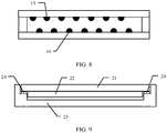
- first support bump 15 and the second support bump 16 may be directly opposite to each other, as shown in FIG. 4 ; or may be alternately with each other, as shown in FIG. 8 . This is not specifically limited herein.
- first support bump 15 and the second support bump 16 each in FIG. 4 to FIG. 8 are schematically illustrated as a hemisphere shape.
- first support bump 15 and the second support bump 16 each may be alternatively in a shape such as a cone, a tetrahedron, a cuboid, or the like.
- shapes of the first support bump 15 and the second support bump 16 are not limited herein.
- a material of the first cover-plate layer 11 and the second cover-plate layer 12 may be an inorganic material or an organic material.
- the first cover-plate layer 11 and the second cover-plate layer 12 may include a PI thin film or glass, where the PI thin film or glass is commonly used in a current terminal product.
- the first cover-plate layer 11 is an outer side that is of the flexible cover plate and that is directly exposed to a user for contact
- base materials of the first cover-plate layer 11 and the second cover-plate layer 12 are PI thin films
- a hardened coating layer with a specific thickness needs to be coated on an outer side of the first cover-plate layer 11, to protect the PI thin film from scratches; or when the base materials of the first cover-plate layer 11 and the second cover-plate layer 12 are glass, an anti-fingerprint coating layer with a specific thickness needs to be coated on the outer side of the first cover-plate layer 11, thereby improving abrasion resistance, dirt resistance, and the like of the first cover-plate layer 11.
- first support bump 15 and the second support bump 16 each may be attached in the following manner: bonding, mold pressing, or coating. This is not specifically limited herein.
- the first support bump 15 and the second support bump 16 may include transparent resin. This is not specifically limited herein.
- the flexible display apparatus 202 includes the flexible cover plate 2001 and the display layer 2002, where the flexible cover plate 2001 is bonded to the display layer 2002.
- the flexible cover plate 2001 is the flexible cover plate according to any one of FIG. 4 to FIG. 8 .
- the display layer 2002 is a display layer with a touch function, and can implement a function of a touch panel.
- the flexible display apparatus may further include a touch panel.
- the flexible display apparatus 301 may include the flexible cover plate 3001, the touch panel 3002, and the display layer 3003, and the flexible cover plate 3001, the touch panel 3002, and the display layer 3003 are sequentially bonded.
- the display layer may be an OLED display layer or an LCD display layer. This is not specifically limited herein.
- the flexible terminal product includes a flexible display apparatus and a foldable mechanism 23, where the flexible display apparatus includes a flexible cover plate 21 and a display layer 22.
- the display layer 22 of the flexible display apparatus is bonded to the foldable mechanism 23 by using adhesive 24.
- the flexible display apparatus is the foregoing flexible display apparatus that includes the flexible cover plate according to any one of FIG. 4 to FIG. 8 .
- the foldable mechanism 23 is foldable and may include a housing, a PCB, a chip, and the like. It should be noted that a structural diagram of the flexible terminal product shown in FIG. 9 is merely an example. This is not specifically limited herein.
Landscapes
- Engineering & Computer Science (AREA)
- Theoretical Computer Science (AREA)
- Computer Hardware Design (AREA)
- General Engineering & Computer Science (AREA)
- Physics & Mathematics (AREA)
- General Physics & Mathematics (AREA)
- Human Computer Interaction (AREA)
- Microelectronics & Electronic Packaging (AREA)
- Chemical & Material Sciences (AREA)
- Organic Chemistry (AREA)
- Electroluminescent Light Sources (AREA)
- Devices For Indicating Variable Information By Combining Individual Elements (AREA)
- Liquid Crystal (AREA)
Applications Claiming Priority (2)
| Application Number | Priority Date | Filing Date | Title |
|---|---|---|---|
| CN201721535113.7U CN207818084U (zh) | 2017-11-16 | 2017-11-16 | 一种柔性盖板、柔性显示装置以及柔性终端产品 |
| PCT/CN2018/095141 WO2019095706A1 (zh) | 2017-11-16 | 2018-07-10 | 一种柔性盖板、柔性显示装置以及柔性终端产品 |
Publications (3)
| Publication Number | Publication Date |
|---|---|
| EP3699892A1 true EP3699892A1 (de) | 2020-08-26 |
| EP3699892A4 EP3699892A4 (de) | 2020-12-23 |
| EP3699892B1 EP3699892B1 (de) | 2025-06-25 |
Family
ID=63333619
Family Applications (1)
| Application Number | Title | Priority Date | Filing Date |
|---|---|---|---|
| EP18879188.3A Active EP3699892B1 (de) | 2017-11-16 | 2018-07-10 | Flexible abdeckplatte, flexible anzeigevorrichtung und flexibles endgerät |
Country Status (4)
| Country | Link |
|---|---|
| US (1) | US11320864B2 (de) |
| EP (1) | EP3699892B1 (de) |
| CN (1) | CN207818084U (de) |
| WO (1) | WO2019095706A1 (de) |
Families Citing this family (27)
| Publication number | Priority date | Publication date | Assignee | Title |
|---|---|---|---|---|
| CN108962028B (zh) * | 2018-07-10 | 2020-03-31 | 云谷(固安)科技有限公司 | 柔性显示屏盖板、柔性显示模组和柔性显示装置 |
| CN109326220B (zh) * | 2018-09-20 | 2021-06-29 | 云谷(固安)科技有限公司 | 盖板及其制造方法、柔性显示模组和电子设备 |
| CN109285454B (zh) * | 2018-09-21 | 2021-06-22 | 云谷(固安)科技有限公司 | 盖板结构、显示装置及盖板结构制备方法 |
| CN110969939A (zh) * | 2018-09-28 | 2020-04-07 | 上海和辉光电有限公司 | 一种可折叠显示屏及显示装置 |
| CN109166461B (zh) * | 2018-09-30 | 2022-02-22 | 广州国显科技有限公司 | 显示面板及其制造方法、以及显示装置 |
| CN109192075B (zh) * | 2018-10-30 | 2022-01-25 | 云谷(固安)科技有限公司 | 柔性盖板及其制备方法 |
| US11127923B2 (en) * | 2018-12-18 | 2021-09-21 | Wuhan China Star Optoelectronics Semiconductor Display Technology Co., Ltd. | Display device |
| CN109671353B (zh) * | 2018-12-18 | 2020-09-08 | 武汉华星光电半导体显示技术有限公司 | 显示装置 |
| CN111522394B (zh) * | 2019-02-01 | 2025-06-24 | 北京小米移动软件有限公司 | 显示面板及其加工工艺、电子设备 |
| CN111599268B (zh) * | 2019-02-20 | 2021-09-14 | 华为技术有限公司 | 柔性显示盖板、显示面板及显示装置 |
| CN109920331B (zh) * | 2019-02-23 | 2020-05-05 | 昆山工研院新型平板显示技术中心有限公司 | 显示面板及显示装置 |
| CN112185247A (zh) * | 2019-07-03 | 2021-01-05 | 华为技术有限公司 | 柔性显示盖板、柔性显示模组和柔性显示装置 |
| CN110517588A (zh) * | 2019-08-29 | 2019-11-29 | 京东方科技集团股份有限公司 | 柔性显示盖板及其制备方法、可折叠显示装置 |
| CN112462864A (zh) * | 2019-09-06 | 2021-03-09 | 北京小米移动软件有限公司 | 折叠屏用盖板、折叠屏及智能设备 |
| CN110675753B (zh) * | 2019-09-30 | 2022-06-03 | 昆山工研院新型平板显示技术中心有限公司 | 一种盖板、盖板的制备方法和柔性显示屏 |
| CN110807990A (zh) * | 2019-10-14 | 2020-02-18 | 武汉华星光电半导体显示技术有限公司 | 一种耐弯折盖窗口及其制备方法 |
| CN111128031A (zh) * | 2020-01-15 | 2020-05-08 | 昆山工研院新型平板显示技术中心有限公司 | 柔性显示盖板及其修复方法、柔性显示模组及显示装置 |
| CN111599844B (zh) | 2020-05-28 | 2022-09-09 | 京东方科技集团股份有限公司 | 柔性显示装置及其制造方法 |
| CN111818200B (zh) * | 2020-06-10 | 2022-02-15 | 维沃移动通信有限公司 | 一种电子设备 |
| CN112038500B (zh) * | 2020-08-27 | 2021-12-28 | 武汉华星光电半导体显示技术有限公司 | 显示模组 |
| CN114449791B (zh) * | 2020-10-30 | 2024-01-23 | 北京小米移动软件有限公司 | 电子设备 |
| KR20230071805A (ko) * | 2021-11-15 | 2023-05-24 | 삼성디스플레이 주식회사 | 표시 장치 |
| CN115240562B (zh) * | 2022-08-25 | 2024-01-30 | 昆山国显光电有限公司 | 显示模组及显示装置 |
| CN116092382A (zh) * | 2022-12-30 | 2023-05-09 | 上海天马微电子有限公司 | 一种可折叠膜材结构及其制备方法、显示面板和显示装置 |
| CN116168612A (zh) * | 2023-02-22 | 2023-05-26 | 维沃移动通信有限公司 | 显示组件和电子设备 |
| CN116312234A (zh) * | 2023-02-27 | 2023-06-23 | 云谷(固安)科技有限公司 | 显示模组及电子设备 |
| CN118658375A (zh) * | 2024-07-05 | 2024-09-17 | 武汉天马微电子有限公司上海分公司 | 盖板及显示装置 |
Family Cites Families (24)
| Publication number | Priority date | Publication date | Assignee | Title |
|---|---|---|---|---|
| EP0882982A1 (de) * | 1997-06-04 | 1998-12-09 | Vrije Universiteit Brussel | Verfahren und Vorrichtung zur Trennung eines Fluids |
| CN102033385A (zh) * | 2003-10-24 | 2011-04-27 | 伊英克公司 | 电光显示器 |
| CN101598865B (zh) * | 2009-07-16 | 2011-01-05 | 友达光电股份有限公司 | 可挠式显示装置 |
| US12578684B2 (en) * | 2009-08-21 | 2026-03-17 | Preciflex Sa | Visual indicator and fluid dispenser |
| JP2011237771A (ja) * | 2010-04-12 | 2011-11-24 | Seiko Epson Corp | 電気泳動表示装置および電子機器 |
| JP2012093626A (ja) * | 2010-10-28 | 2012-05-17 | Seiko Epson Corp | 表示シート、表示装置および電子機器 |
| JP6077194B2 (ja) * | 2010-12-07 | 2017-02-08 | ソニー株式会社 | 導電性光学素子ならびに情報入力装置および表示装置 |
| US20120256867A1 (en) * | 2011-04-09 | 2012-10-11 | Annacone William R | Underwater touchscreen system |
| JP2013239812A (ja) * | 2012-05-14 | 2013-11-28 | Sharp Corp | 携帯端末 |
| KR102265083B1 (ko) * | 2013-08-22 | 2021-06-15 | 삼성전자주식회사 | 가변강성 필름, 가변강성 유연 디스플레이 및 이의 제조 방법 |
| KR20150084257A (ko) | 2014-01-13 | 2015-07-22 | 삼성디스플레이 주식회사 | 플렉서블 표시장치 |
| US10020462B1 (en) * | 2015-07-30 | 2018-07-10 | Apple Inc. | Electronic devices with flexible displays |
| US10345905B2 (en) * | 2015-09-08 | 2019-07-09 | Apple Inc. | Electronic devices with deformable displays |
| JP2019507462A (ja) * | 2015-12-28 | 2019-03-14 | スリーエム イノベイティブ プロパティズ カンパニー | 流体キャビティ構成を有する可撓性電子デバイス |
| KR102456540B1 (ko) * | 2016-05-02 | 2022-10-20 | 삼성전자주식회사 | 폐쇄형 윈도우를 포함하는 전자 장치 및 그 제조 방법 |
| CN106125846B (zh) * | 2016-07-08 | 2018-06-26 | 广东欧珀移动通信有限公司 | 柔性屏支撑结构、柔性显示屏模组及移动终端 |
| KR102038740B1 (ko) * | 2016-07-19 | 2019-10-31 | (주)화이트스톤 | 곡면 커버 글라스 보호필름, 이의 부착장치 및 이를 이용한 곡면 커버 글라스 보호필름의 부착방법 |
| KR102680552B1 (ko) * | 2016-11-30 | 2024-07-01 | 엘지디스플레이 주식회사 | 커버 플레이트 및 이를 포함하는 폴더블 표시장치 |
| US10592018B2 (en) * | 2017-03-14 | 2020-03-17 | Tactus Technology, Inc. | Elastomer tie layer and methods |
| CN107123371B (zh) * | 2017-04-27 | 2019-08-02 | 京东方科技集团股份有限公司 | 一种柔性显示面板及其制作方法、柔性显示装置 |
| JP7110713B2 (ja) * | 2017-05-12 | 2022-08-02 | Agc株式会社 | 屈曲基材の製造方法 |
| US20190312228A1 (en) * | 2017-07-14 | 2019-10-10 | Sharp Kabushiki Kaisha | Manufacturing method of electro-optical device and electro-optical device |
| US10275069B2 (en) * | 2017-09-22 | 2019-04-30 | Apple Inc. | Pressure resistant force sensing enclosure |
| WO2019071835A1 (zh) * | 2017-10-13 | 2019-04-18 | 华为技术有限公司 | 一种高强度防指纹玻璃及其制备方法,以及高强度防指纹玻璃外观件及其制备方法 |
-
2017
- 2017-11-16 CN CN201721535113.7U patent/CN207818084U/zh active Active
-
2018
- 2018-07-10 EP EP18879188.3A patent/EP3699892B1/de active Active
- 2018-07-10 WO PCT/CN2018/095141 patent/WO2019095706A1/zh not_active Ceased
-
2020
- 2020-05-14 US US16/874,030 patent/US11320864B2/en active Active
Also Published As
| Publication number | Publication date |
|---|---|
| EP3699892A4 (de) | 2020-12-23 |
| EP3699892B1 (de) | 2025-06-25 |
| US20200272204A1 (en) | 2020-08-27 |
| CN207818084U (zh) | 2018-09-04 |
| WO2019095706A1 (zh) | 2019-05-23 |
| US11320864B2 (en) | 2022-05-03 |
Similar Documents
| Publication | Publication Date | Title |
|---|---|---|
| US11320864B2 (en) | Flexible cover plate, flexible display apparatus, and flexible terminal product | |
| KR102338473B1 (ko) | 윈도우 커버, 이를 가지는 디스플레이장치 및 그 제조방법 | |
| KR20220024880A (ko) | 유연한 디스플레이 커버 플레이트, 유연한 디스플레이 모듈 및 유연한 디스플레이 디바이스 | |
| CN205899447U (zh) | 一种显示装置 | |
| JP6181391B2 (ja) | タッチスクリーンとその製造方法、およびそれを備える携帯端末 | |
| CN104063084B (zh) | 触控显示装置 | |
| CN114495706A (zh) | 电子设备 | |
| CN104503615B (zh) | 一种触控显示器 | |
| JP2017191319A (ja) | フレキシブル・ディスプレイ・スタックアップおよび組立方法 | |
| CN103913861A (zh) | 平板显示装置及其制造方法 | |
| KR20150042046A (ko) | 터치센서 | |
| WO2017030707A1 (en) | Bendable device with a window top layer | |
| CN209690889U (zh) | 一种触控模组及触控显示屏 | |
| KR20160043965A (ko) | 정전 용량형 터치 패널 | |
| WO2015129662A1 (ja) | 電子機器 | |
| US20120261240A1 (en) | Key device and electronic apparatus containing the key device | |
| EP2555092A1 (de) | Elektronische anwendung und damit ausgestattetes mobilgerät | |
| CN111625142A (zh) | 保护盖板、触控组件、显示屏以及电子设备 | |
| JP2014225126A (ja) | 静電容量型タッチパネル | |
| CN220820973U (zh) | 柔性显示装置 | |
| CN114697415B (zh) | 折叠屏的保护机构和可折叠电子设备 | |
| CN105718095A (zh) | 触控显示装置 | |
| CN103265897B (zh) | 一种光学粘接件及触摸显示装置 | |
| JP2005222266A (ja) | タッチセンサ付き表示装置、およびタッチセンサ付き表示装置用両面接着テープ | |
| CN210851554U (zh) | 一种用于柔性显示面板的保护贴膜 |
Legal Events
| Date | Code | Title | Description |
|---|---|---|---|
| STAA | Information on the status of an ep patent application or granted ep patent |
Free format text: STATUS: THE INTERNATIONAL PUBLICATION HAS BEEN MADE |
|
| PUAI | Public reference made under article 153(3) epc to a published international application that has entered the european phase |
Free format text: ORIGINAL CODE: 0009012 |
|
| STAA | Information on the status of an ep patent application or granted ep patent |
Free format text: STATUS: REQUEST FOR EXAMINATION WAS MADE |
|
| 17P | Request for examination filed |
Effective date: 20200518 |
|
| AK | Designated contracting states |
Kind code of ref document: A1 Designated state(s): AL AT BE BG CH CY CZ DE DK EE ES FI FR GB GR HR HU IE IS IT LI LT LU LV MC MK MT NL NO PL PT RO RS SE SI SK SM TR |
|
| AX | Request for extension of the european patent |
Extension state: BA ME |
|
| A4 | Supplementary search report drawn up and despatched |
Effective date: 20201120 |
|
| RIC1 | Information provided on ipc code assigned before grant |
Ipc: H05K 5/02 20060101ALI20201116BHEP Ipc: H04M 1/02 20060101ALI20201116BHEP Ipc: G09F 9/30 20060101AFI20201116BHEP Ipc: G06F 1/16 20060101ALI20201116BHEP |
|
| DAV | Request for validation of the european patent (deleted) | ||
| DAX | Request for extension of the european patent (deleted) | ||
| STAA | Information on the status of an ep patent application or granted ep patent |
Free format text: STATUS: EXAMINATION IS IN PROGRESS |
|
| 17Q | First examination report despatched |
Effective date: 20230303 |
|
| GRAP | Despatch of communication of intention to grant a patent |
Free format text: ORIGINAL CODE: EPIDOSNIGR1 |
|
| STAA | Information on the status of an ep patent application or granted ep patent |
Free format text: STATUS: GRANT OF PATENT IS INTENDED |
|
| INTG | Intention to grant announced |
Effective date: 20250218 |
|
| GRAS | Grant fee paid |
Free format text: ORIGINAL CODE: EPIDOSNIGR3 |
|
| GRAA | (expected) grant |
Free format text: ORIGINAL CODE: 0009210 |
|
| STAA | Information on the status of an ep patent application or granted ep patent |
Free format text: STATUS: THE PATENT HAS BEEN GRANTED |
|
| AK | Designated contracting states |
Kind code of ref document: B1 Designated state(s): AL AT BE BG CH CY CZ DE DK EE ES FI FR GB GR HR HU IE IS IT LI LT LU LV MC MK MT NL NO PL PT RO RS SE SI SK SM TR |
|
| REG | Reference to a national code |
Ref country code: GB Ref legal event code: FG4D |
|
| REG | Reference to a national code |
Ref country code: CH Ref legal event code: EP |
|
| REG | Reference to a national code |
Ref country code: DE Ref legal event code: R096 Ref document number: 602018083015 Country of ref document: DE |
|
| REG | Reference to a national code |
Ref country code: CH Ref legal event code: EP |
|
| REG | Reference to a national code |
Ref country code: IE Ref legal event code: FG4D |
|
| PG25 | Lapsed in a contracting state [announced via postgrant information from national office to epo] |
Ref country code: FI Free format text: LAPSE BECAUSE OF FAILURE TO SUBMIT A TRANSLATION OF THE DESCRIPTION OR TO PAY THE FEE WITHIN THE PRESCRIBED TIME-LIMIT Effective date: 20250625 |
|
| PGFP | Annual fee paid to national office [announced via postgrant information from national office to epo] |
Ref country code: DE Payment date: 20250708 Year of fee payment: 8 |
|
| REG | Reference to a national code |
Ref country code: LT Ref legal event code: MG9D |
|
| PG25 | Lapsed in a contracting state [announced via postgrant information from national office to epo] |
Ref country code: GR Free format text: LAPSE BECAUSE OF FAILURE TO SUBMIT A TRANSLATION OF THE DESCRIPTION OR TO PAY THE FEE WITHIN THE PRESCRIBED TIME-LIMIT Effective date: 20250926 Ref country code: NO Free format text: LAPSE BECAUSE OF FAILURE TO SUBMIT A TRANSLATION OF THE DESCRIPTION OR TO PAY THE FEE WITHIN THE PRESCRIBED TIME-LIMIT Effective date: 20250925 |
|
| PG25 | Lapsed in a contracting state [announced via postgrant information from national office to epo] |
Ref country code: BG Free format text: LAPSE BECAUSE OF FAILURE TO SUBMIT A TRANSLATION OF THE DESCRIPTION OR TO PAY THE FEE WITHIN THE PRESCRIBED TIME-LIMIT Effective date: 20250625 |
|
| PGFP | Annual fee paid to national office [announced via postgrant information from national office to epo] |
Ref country code: GB Payment date: 20250710 Year of fee payment: 8 |
|
| PG25 | Lapsed in a contracting state [announced via postgrant information from national office to epo] |
Ref country code: HR Free format text: LAPSE BECAUSE OF FAILURE TO SUBMIT A TRANSLATION OF THE DESCRIPTION OR TO PAY THE FEE WITHIN THE PRESCRIBED TIME-LIMIT Effective date: 20250625 |
|
| PG25 | Lapsed in a contracting state [announced via postgrant information from national office to epo] |
Ref country code: RS Free format text: LAPSE BECAUSE OF FAILURE TO SUBMIT A TRANSLATION OF THE DESCRIPTION OR TO PAY THE FEE WITHIN THE PRESCRIBED TIME-LIMIT Effective date: 20250925 |
|
| PG25 | Lapsed in a contracting state [announced via postgrant information from national office to epo] |
Ref country code: LV Free format text: LAPSE BECAUSE OF FAILURE TO SUBMIT A TRANSLATION OF THE DESCRIPTION OR TO PAY THE FEE WITHIN THE PRESCRIBED TIME-LIMIT Effective date: 20250625 |
|
| REG | Reference to a national code |
Ref country code: NL Ref legal event code: MP Effective date: 20250625 |
|
| PG25 | Lapsed in a contracting state [announced via postgrant information from national office to epo] |
Ref country code: NL Free format text: LAPSE BECAUSE OF FAILURE TO SUBMIT A TRANSLATION OF THE DESCRIPTION OR TO PAY THE FEE WITHIN THE PRESCRIBED TIME-LIMIT Effective date: 20250625 |
|
| PG25 | Lapsed in a contracting state [announced via postgrant information from national office to epo] |
Ref country code: PT Free format text: LAPSE BECAUSE OF FAILURE TO SUBMIT A TRANSLATION OF THE DESCRIPTION OR TO PAY THE FEE WITHIN THE PRESCRIBED TIME-LIMIT Effective date: 20251027 |
|
| REG | Reference to a national code |
Ref country code: AT Ref legal event code: MK05 Ref document number: 1807386 Country of ref document: AT Kind code of ref document: T Effective date: 20250625 |
|
| PG25 | Lapsed in a contracting state [announced via postgrant information from national office to epo] |
Ref country code: IS Free format text: LAPSE BECAUSE OF FAILURE TO SUBMIT A TRANSLATION OF THE DESCRIPTION OR TO PAY THE FEE WITHIN THE PRESCRIBED TIME-LIMIT Effective date: 20251025 |
|
| PG25 | Lapsed in a contracting state [announced via postgrant information from national office to epo] |
Ref country code: AT Free format text: LAPSE BECAUSE OF FAILURE TO SUBMIT A TRANSLATION OF THE DESCRIPTION OR TO PAY THE FEE WITHIN THE PRESCRIBED TIME-LIMIT Effective date: 20250625 Ref country code: SM Free format text: LAPSE BECAUSE OF FAILURE TO SUBMIT A TRANSLATION OF THE DESCRIPTION OR TO PAY THE FEE WITHIN THE PRESCRIBED TIME-LIMIT Effective date: 20250625 |
|
| PG25 | Lapsed in a contracting state [announced via postgrant information from national office to epo] |
Ref country code: CZ Free format text: LAPSE BECAUSE OF FAILURE TO SUBMIT A TRANSLATION OF THE DESCRIPTION OR TO PAY THE FEE WITHIN THE PRESCRIBED TIME-LIMIT Effective date: 20250625 |
|
| PG25 | Lapsed in a contracting state [announced via postgrant information from national office to epo] |
Ref country code: PL Free format text: LAPSE BECAUSE OF FAILURE TO SUBMIT A TRANSLATION OF THE DESCRIPTION OR TO PAY THE FEE WITHIN THE PRESCRIBED TIME-LIMIT Effective date: 20250625 |
|
| PG25 | Lapsed in a contracting state [announced via postgrant information from national office to epo] |
Ref country code: EE Free format text: LAPSE BECAUSE OF FAILURE TO SUBMIT A TRANSLATION OF THE DESCRIPTION OR TO PAY THE FEE WITHIN THE PRESCRIBED TIME-LIMIT Effective date: 20250625 |
|
| PG25 | Lapsed in a contracting state [announced via postgrant information from national office to epo] |
Ref country code: SK Free format text: LAPSE BECAUSE OF FAILURE TO SUBMIT A TRANSLATION OF THE DESCRIPTION OR TO PAY THE FEE WITHIN THE PRESCRIBED TIME-LIMIT Effective date: 20250625 |
|
| PG25 | Lapsed in a contracting state [announced via postgrant information from national office to epo] |
Ref country code: ES Free format text: LAPSE BECAUSE OF FAILURE TO SUBMIT A TRANSLATION OF THE DESCRIPTION OR TO PAY THE FEE WITHIN THE PRESCRIBED TIME-LIMIT Effective date: 20250625 |
|
| REG | Reference to a national code |
Ref country code: CH Ref legal event code: H13 Free format text: ST27 STATUS EVENT CODE: U-0-0-H10-H13 (AS PROVIDED BY THE NATIONAL OFFICE) Effective date: 20260224 |
|
| PG25 | Lapsed in a contracting state [announced via postgrant information from national office to epo] |
Ref country code: RO Free format text: LAPSE BECAUSE OF FAILURE TO SUBMIT A TRANSLATION OF THE DESCRIPTION OR TO PAY THE FEE WITHIN THE PRESCRIBED TIME-LIMIT Effective date: 20250625 Ref country code: LU Free format text: LAPSE BECAUSE OF NON-PAYMENT OF DUE FEES Effective date: 20250710 |
|
| REG | Reference to a national code |
Ref country code: BE Ref legal event code: MM Effective date: 20250731 |
|
| PG25 | Lapsed in a contracting state [announced via postgrant information from national office to epo] |
Ref country code: MC Free format text: LAPSE BECAUSE OF FAILURE TO SUBMIT A TRANSLATION OF THE DESCRIPTION OR TO PAY THE FEE WITHIN THE PRESCRIBED TIME-LIMIT Effective date: 20250625 |
|
| PG25 | Lapsed in a contracting state [announced via postgrant information from national office to epo] |
Ref country code: DK Free format text: LAPSE BECAUSE OF FAILURE TO SUBMIT A TRANSLATION OF THE DESCRIPTION OR TO PAY THE FEE WITHIN THE PRESCRIBED TIME-LIMIT Effective date: 20250625 |
|
| PG25 | Lapsed in a contracting state [announced via postgrant information from national office to epo] |
Ref country code: BE Free format text: LAPSE BECAUSE OF NON-PAYMENT OF DUE FEES Effective date: 20250731 Ref country code: IT Free format text: LAPSE BECAUSE OF FAILURE TO SUBMIT A TRANSLATION OF THE DESCRIPTION OR TO PAY THE FEE WITHIN THE PRESCRIBED TIME-LIMIT Effective date: 20250625 |
|
| PG25 | Lapsed in a contracting state [announced via postgrant information from national office to epo] |
Ref country code: CH Free format text: LAPSE BECAUSE OF NON-PAYMENT OF DUE FEES Effective date: 20250731 |
|
| PLBE | No opposition filed within time limit |
Free format text: ORIGINAL CODE: 0009261 |
|
| STAA | Information on the status of an ep patent application or granted ep patent |
Free format text: STATUS: NO OPPOSITION FILED WITHIN TIME LIMIT |