EP3699896B1 - Projektionsanzeigevorrichtung und projektionsanzeigeverfahren - Google Patents
Projektionsanzeigevorrichtung und projektionsanzeigeverfahren Download PDFInfo
- Publication number
- EP3699896B1 EP3699896B1 EP19183428.2A EP19183428A EP3699896B1 EP 3699896 B1 EP3699896 B1 EP 3699896B1 EP 19183428 A EP19183428 A EP 19183428A EP 3699896 B1 EP3699896 B1 EP 3699896B1
- Authority
- EP
- European Patent Office
- Prior art keywords
- frame
- video signal
- frames
- pixel data
- complement
- Prior art date
- Legal status (The legal status is an assumption and is not a legal conclusion. Google has not performed a legal analysis and makes no representation as to the accuracy of the status listed.)
- Active
Links
Images

Classifications
-
- G—PHYSICS
- G09—EDUCATION; CRYPTOGRAPHY; DISPLAY; ADVERTISING; SEALS
- G09G—ARRANGEMENTS OR CIRCUITS FOR CONTROL OF INDICATING DEVICES USING STATIC MEANS TO PRESENT VARIABLE INFORMATION
- G09G3/00—Control arrangements or circuits, of interest only in connection with visual indicators other than cathode-ray tubes
- G09G3/001—Control arrangements or circuits, of interest only in connection with visual indicators other than cathode-ray tubes using specific devices not provided for in groups G09G3/02 - G09G3/36, e.g. using an intermediate record carrier such as a film slide; Projection systems; Display of non-alphanumerical information, solely or in combination with alphanumerical information, e.g. digital display on projected diapositive as background
- G09G3/002—Control arrangements or circuits, of interest only in connection with visual indicators other than cathode-ray tubes using specific devices not provided for in groups G09G3/02 - G09G3/36, e.g. using an intermediate record carrier such as a film slide; Projection systems; Display of non-alphanumerical information, solely or in combination with alphanumerical information, e.g. digital display on projected diapositive as background to project the image of a two-dimensional display, such as an array of light emitting or modulating elements or a CRT
-
- H—ELECTRICITY
- H04—ELECTRIC COMMUNICATION TECHNIQUE
- H04N—PICTORIAL COMMUNICATION, e.g. TELEVISION
- H04N9/00—Details of colour television systems
- H04N9/12—Picture reproducers
- H04N9/31—Projection devices for colour picture display, e.g. using electronic spatial light modulators [ESLM]
- H04N9/3141—Constructional details thereof
-
- H—ELECTRICITY
- H04—ELECTRIC COMMUNICATION TECHNIQUE
- H04N—PICTORIAL COMMUNICATION, e.g. TELEVISION
- H04N7/00—Television systems
- H04N7/01—Conversion of standards, e.g. involving analogue television standards or digital television standards processed at pixel level
- H04N7/0135—Conversion of standards, e.g. involving analogue television standards or digital television standards processed at pixel level involving interpolation processes
- H04N7/014—Conversion of standards, e.g. involving analogue television standards or digital television standards processed at pixel level involving interpolation processes involving the use of motion vectors
-
- G—PHYSICS
- G06—COMPUTING OR CALCULATING; COUNTING
- G06T—IMAGE DATA PROCESSING OR GENERATION, IN GENERAL
- G06T7/00—Image analysis
- G06T7/20—Analysis of motion
-
- H—ELECTRICITY
- H04—ELECTRIC COMMUNICATION TECHNIQUE
- H04N—PICTORIAL COMMUNICATION, e.g. TELEVISION
- H04N5/00—Details of television systems
- H04N5/74—Projection arrangements for image reproduction, e.g. using eidophor
- H04N5/7408—Direct viewing projectors, e.g. an image displayed on a video CRT or LCD display being projected on a screen
-
- H—ELECTRICITY
- H04—ELECTRIC COMMUNICATION TECHNIQUE
- H04N—PICTORIAL COMMUNICATION, e.g. TELEVISION
- H04N9/00—Details of colour television systems
- H04N9/12—Picture reproducers
- H04N9/31—Projection devices for colour picture display, e.g. using electronic spatial light modulators [ESLM]
- H04N9/3179—Video signal processing therefor
- H04N9/3188—Scale or resolution adjustment
-
- G—PHYSICS
- G09—EDUCATION; CRYPTOGRAPHY; DISPLAY; ADVERTISING; SEALS
- G09G—ARRANGEMENTS OR CIRCUITS FOR CONTROL OF INDICATING DEVICES USING STATIC MEANS TO PRESENT VARIABLE INFORMATION
- G09G2340/00—Aspects of display data processing
- G09G2340/04—Changes in size, position or resolution of an image
- G09G2340/0407—Resolution change, inclusive of the use of different resolutions for different screen areas
-
- G—PHYSICS
- G09—EDUCATION; CRYPTOGRAPHY; DISPLAY; ADVERTISING; SEALS
- G09G—ARRANGEMENTS OR CIRCUITS FOR CONTROL OF INDICATING DEVICES USING STATIC MEANS TO PRESENT VARIABLE INFORMATION
- G09G2340/00—Aspects of display data processing
- G09G2340/04—Changes in size, position or resolution of an image
- G09G2340/0407—Resolution change, inclusive of the use of different resolutions for different screen areas
- G09G2340/0414—Vertical resolution change
-
- G—PHYSICS
- G09—EDUCATION; CRYPTOGRAPHY; DISPLAY; ADVERTISING; SEALS
- G09G—ARRANGEMENTS OR CIRCUITS FOR CONTROL OF INDICATING DEVICES USING STATIC MEANS TO PRESENT VARIABLE INFORMATION
- G09G2340/00—Aspects of display data processing
- G09G2340/04—Changes in size, position or resolution of an image
- G09G2340/0407—Resolution change, inclusive of the use of different resolutions for different screen areas
- G09G2340/0421—Horizontal resolution change
-
- G—PHYSICS
- G09—EDUCATION; CRYPTOGRAPHY; DISPLAY; ADVERTISING; SEALS
- G09G—ARRANGEMENTS OR CIRCUITS FOR CONTROL OF INDICATING DEVICES USING STATIC MEANS TO PRESENT VARIABLE INFORMATION
- G09G2340/00—Aspects of display data processing
- G09G2340/04—Changes in size, position or resolution of an image
- G09G2340/0407—Resolution change, inclusive of the use of different resolutions for different screen areas
- G09G2340/0435—Change or adaptation of the frame rate of the video stream
-
- G—PHYSICS
- G09—EDUCATION; CRYPTOGRAPHY; DISPLAY; ADVERTISING; SEALS
- G09G—ARRANGEMENTS OR CIRCUITS FOR CONTROL OF INDICATING DEVICES USING STATIC MEANS TO PRESENT VARIABLE INFORMATION
- G09G2340/00—Aspects of display data processing
- G09G2340/16—Determination of a pixel data signal depending on the signal applied in the previous frame
-
- G—PHYSICS
- G09—EDUCATION; CRYPTOGRAPHY; DISPLAY; ADVERTISING; SEALS
- G09G—ARRANGEMENTS OR CIRCUITS FOR CONTROL OF INDICATING DEVICES USING STATIC MEANS TO PRESENT VARIABLE INFORMATION
- G09G3/00—Control arrangements or circuits, of interest only in connection with visual indicators other than cathode-ray tubes
- G09G3/007—Use of pixel shift techniques, e.g. by mechanical shift of the physical pixels or by optical shift of the perceived pixels
-
- G—PHYSICS
- G09—EDUCATION; CRYPTOGRAPHY; DISPLAY; ADVERTISING; SEALS
- G09G—ARRANGEMENTS OR CIRCUITS FOR CONTROL OF INDICATING DEVICES USING STATIC MEANS TO PRESENT VARIABLE INFORMATION
- G09G5/00—Control arrangements or circuits for visual indicators common to cathode-ray tube indicators and other visual indicators
- G09G5/36—Control arrangements or circuits for visual indicators common to cathode-ray tube indicators and other visual indicators characterised by the display of a graphic pattern, e.g. using an all-points-addressable [APA] memory
- G09G5/39—Control of the bit-mapped memory
- G09G5/391—Resolution modifying circuits, e.g. variable screen formats
Definitions
- the present disclosure relates to a projection display apparatus and a display method, and in particular to a projection display apparatus and a display method applied to frame insertion and resolution improvement.
- An image having a high resolution provides clear detail(s) and high quality of viewing, and is thus helpful for improving the user experience and many applications.
- Many video signals have been developed to have a resolution of 4K (3840 ⁇ 2160), even reaching a resolution of 8K (7680 ⁇ 4320).
- a general projection display apparatus lacks a projection display component corresponding to the resolution of 8K apparatus. Therefore, the resolution of 8K is not supported by current projection display apparatus.
- US 2017/0019648 A1 provides a projection image display apparatus that can form the motion-interpolation image processing circuits with ease.
- US 2008/0284763 A1 provides an image display apparatus to reduce motion blur without increasing the amount of pixel data that must be transferred to the display device.
- US 2010/0053429 A1 provides a picture signal processing unit that performs frame rate conversion of a picture signal by using motion compensation.
- US 2014/0340492 A1 provides a projection display apparatus which can project an image by shifting an optical path of an image light in a predetermined cycle.
- the projection display apparatus includes a processing circuit and an image projection display device.
- the processing circuit is configured to perform a dynamic operation compensation according to a first frame and second frame in a first video signal to generate a complement frame between the first frame and the second frame, and to combine the first frame and the complement frame into a third frame, in which the first frame and the second frame are continuous frames, and the processing circuit is further configured to decompose the third frame to generate a plurality of fourth frames, and to output the plurality of fourth frames as a second video signal, and a resolution of the first video signal is higher than a resolution of the second video signal.
- the image projection display device is configured to project and display the second video signal, in which the image projection display device has an original resolution equal to the resolution of the second video signal.
- An aspect of the present disclosure relates to a display method according to claim 3.
- the display method includes the following operations: performing a dynamic operation compensation on a first frame and a second frame in a first video signal to generate a complement frame between the first frame and the second frame, and combining the first frame and the complement frame are a third frame, in which the first frame and the second frame are continuous frames; decomposing the third frame to generate a plurality of fourth frames, and outputting the plurality of fourth frames as a second video signal, in which a resolution of the first video signal is higher than a resolution of the second video signal; and displaying the second video signal by an image projection display device.
- the projection display apparatus and the display method provided by the embodiments of the present disclosure can generate a higher resolution image by using a projection apparatus that has lower original resolution.
- first, second, third etc. may be used herein to describe various elements, components, regions, layers and/or sections, these elements, components, regions, layers and/or sections should not be limited by these terms. These terms are only used to distinguish one element, component, region, layer or section from another element, component, region, layer or section. Thus, a first element, component, region, layer or section discussed below could be termed a second element, component, region, layer or section without departing from the teachings of the present disclosure.
- FIG. 1 is a schematic diagram of a projection display apparatus 100 according to some embodiments of the present disclosure.
- the projection display apparatus 100 is configured to receive a video signal having high resolution, and to use an image projection device which has a lower original resolution to generate an image of the video signal, and to make the image have the aforementioned high resolution equivalently.
- the projection display apparatus 100 is configured to receive a first video signal SIN having a specification of 8K60Hz.
- the projection display apparatus 100 further employs an image projection display device 120 having a resolution of 4K , in order to generate the image (i.e., second video signal SOUT) that is able to provide an effect of 8K resolution effect for human eye, in which the real output specification of the image is 4K240Hz.
- the projection display apparatus 100 may be a digital television, a digital micro mirror, a home projector, a professional projector, etc.
- the projection display apparatus 100 includes a processing circuit 110 and the image projection display device 120.
- the processing circuit 110 is configured to perform operation(s) of a display method 600 described below, in order to generate a projection image.
- the processing circuit 110 may include image processing circuit(s), which may include, for example, a dynamic blur suppression circuit (not shown), an image processing circuit (not shown), a color management circuit (not shown), etc.
- the processing circuit 110 also includes at least one control circuit (not shown) that is configured to control operation(s) and timing of the above image processing circuits.
- the dynamic blur suppression circuit can perform dynamic estimation or compensation (for example, a dynamic operation compensation described later) according to the first video signal SIN to improve the sharpness or smoothness of the image.
- the image processing circuit is configured to perform operations of FIG. 3 and/or FIG. 4 described later.
- the color management circuit is configured to perform operations (e.g., color separation) according to operational requirements.
- the processing circuit 110 can be a combination of processor and memory, in which the functions of the image processing circuits (e.g., dynamic blur suppression circuit, image processing circuit, color management circuit, etc.) may be implemented with at least one computer program code and stored in the memory for use by the processor.
- the functions of the image processing circuits e.g., dynamic blur suppression circuit, image processing circuit, color management circuit, etc.
- the processor is a central processing unit (CPU), an application-specific integrated circuit (ASIC), a multi-processor, a decentralized processing system, or a suitable processor.
- CPU central processing unit
- ASIC application-specific integrated circuit
- multi-processor multi-processor
- decentralized processing system or a suitable processor.
- the memory is a non-transitory computer readable medium.
- the computer readable medium is an electrical, magnetic, optical, infrared, and/or semiconductor system (or apparatus or device).
- non-transitory computer readable medium includes semiconductor or solid state memory, magnetic tape, removable computer diskettes, random access memory (RAM), read only memory (ROM), hard disk and/or optical magnetic disc.
- the computer readable medium includes a CD-ROM, a CD-R/W, and/or a digital video disc (DVD).
- processing circuit 110 is given for illustrative purposes, but the present disclosure is not limited thereto. Various circuits or units to implement the processing circuit 110 are within the scope of the present disclosure.
- the image projection display device 120 includes a digital micro mirror element 121, a multi-axis shifting device 122, a lens 123, and a light source 124.
- the digital micro mirror element 121 may include a matrix formed with a plurality of micro mirrors (not shown). With light transmitted by the light source 124, the digital micro mirror element 121 can project the image via the lens 123. In some embodiments, the multi-axis shifting device 122 can be activated by the projection display apparatus 100 according to the resolution of the first video signal SIN.
- the multi-axis shifting device 122 can include two sets of voice coil motors (not shown) and a lens (not shown).
- One set of voice coils can drive the lens to shift the image projected by the digital micro mirror element 121 along a first axial direction (e.g., a vertical axis).
- Another set of voice coil motors can drive the lens, in order to shift the image in a second axial direction (e.g., horizontal axis) projected by the digital micro mirror element 121.
- a first axial direction e.g., a vertical axis
- Another set of voice coil motors can drive the lens, in order to shift the image in a second axial direction (e.g., horizontal axis) projected by the digital micro mirror element 121.
- the image projection display device 120 has an original resolution of 3840 ⁇ 2160 (also known as 4K resolution).
- the resolution of the first video signal SIN received by the processing circuit 110 is higher than the original resolution of the image projection display device 120.
- the resolution of the first video signal SIN can be 7680 ⁇ 4320 (also referred to as 8K resolution).
- the projection display device when the resolution of the received video signal is greater than the original resolution of the projection display device, the projection display device can only present the image having the original resolution.
- the projection display apparatus 100 of the embodiment of the present disclosure can provide the projection image with high resolution via the image projection display device 120 that has a lower original resolution.
- FIG. 2 is a schematic diagram illustrating an operation 200 of a dynamic operation compensation according to some embodiments of the present disclosure.
- the specification of a first video signal 210 i.e., the first video signal SIN in FIG. 1
- 8K60Hz the specification of a first video signal 210
- the first video signal 210 includes a plurality of continuous frames, which includes a first frame 211 and a second frame 212.
- the processing circuit 110 performs a dynamic operation compensation according to the first frame 211 and the second frame 212 to generate a complement frame 230, and inserts the complement frame 230 between the first frame 211 and the second frame 212.
- the aforementioned first frame 211 and second frame 212 may be any two consecutive frames in the first video signal 210.
- the processing circuit 110 performs the dynamic operation compensation according to the second frame 212 and its next frame (not shown) to generate the complement frame, and the complement frame is inserted between the second frame 212 and the aforementioned next frame (not shown).
- the specification of the processed video signal can be increased to 8K120Hz.
- the above term "continuous" means that two frames are continuous in time, or that two frames are associated with each other based on the encoding, but the present disclosure is not limited thereto.
- the aforementioned dynamic operation compensation is an image processing method of motion estimation and motion compensation (MEMC).
- This image processing method includes operations of de-interlacing and/or motion interpolation.
- the above dynamic operation compensation is given as an example, and the present disclosure is not limited thereto.
- the various types of dynamic operation compensation are within the scope of this disclosure.
- FIG. 3 is a schematic diagram of an operation 300 of combining the first frame 211 and the complement frame 230 in FIG. 2 according to some embodiments of the present disclosure.
- the image of each of the first frame 211 and the complement frame 230 is formed with a plurality of row data, in which the each one of the row data may contain multiple image data values (e.g., pixel values).
- the processing circuit 110 is configured to interleave a plurality of odd row data of the first frame 211 with a plurality of even row data of the complement frame 230 to generate the third frame 320.
- First row data 310 and second row data 314 of the third frame 320 in FIG. 3 are the first row data and the third row data of the first frame 211, respectively.
- Second row data 312 and fourth row data 316 of the third frame 320 are the second row data and the fourth row data of the complement frame 230, respectively.
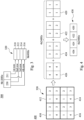
- FIG. 4 is a schematic diagram of an operation 400 of combining a fourth frame according to some embodiments of the present disclosure.
- the processing circuit 110 decomposes the third frame 320 of FIG. 3 into a plurality of blocks (e.g., blocks 410, 412, 414, and 416), and generates a plurality of fourth frames (e.g., frames 420, 422, 424, and 426) according to different pixel data of each of the blocks.
- a plurality of blocks e.g., blocks 410, 412, 414, and 416
- fourth frames e.g., frames 420, 422, 424, and 426
- the processing circuit 110 decomposes the plurality of pixel data of third frame 320 into the plurality of blocks 410, 412, 414, and 416.
- the different pixel data of each of the plurality of blocks 410, 412, 414 and 416 are arranged according to a predetermined direction.
- the above predetermined direction may be a clockwise direction.
- the plurality of pixel data of each of the blocks 410, 412, 414, and 416 are sequentially arranged in a clockwise direction from an upper left corner of the corresponding block.
- the plurality of pixel data are sequentially arranged in the upper left corner, the upper right corner, the lower right corner, and the lower left corner of the corresponding block, and are sequentially numbered as the plurality of pixel data 1 to 4.
- the processing circuit 110 generates a corresponding one of the plurality of fourth frames (e.g., frames 420, 422, 424, and 426) according to the corresponding pixel data of each of the plurality of blocks 410, 412, 414 and 416.
- the processing circuit 110 can combine the pixel data 1 of each of the plurality of blocks 410, 412, 414, and 416 into the fourth frame 420, and combine the pixel data 2 of each of the plurality of blocks 410, 412, 414, and 416 into the fourth frame 422.
- the processing circuit 110 can combine the plurality of pixel data 3 into the fourth frame 424 and combine the plurality of pixel data 4 into a fourth frame 426.
- the processor 110 strings all the generated fourth frames into a second video signal 430.
- the processing circuit 110 sequentially decomposes the 16 pixel points of the third frame 320 into the upper left block 410, the upper right block 412, the lower right block 414, and the lower left block 416.
- the 4 pixel points of each block are sequentially located at the upper left, upper right, lower right and lower left corners and numbered.
- the pixel points that have the same number in the four blocks are the combined into new frames (e.g., fourth frames 420, 422, 424, and 426).
- each of the third frames 320 is decomposed into the four fourth frames (e.g., frames 420, 422, 424, and 426).
- the specification of the second video signal 430 that is formed with all of the fourth frames can be equivalently adjusted to 4K240Hz.
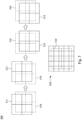
- FIG. 5 is a schematic diagram of an operation 500 of periodically shifting and projecting according to some embodiments of the present disclosure.
- the aforementioned multi-axis shifting device 122 can be used to periodically shift and to project the second video signal 430 in a clockwise direction, in order to produce the projection image with higher resolution. Due to the visual persistence of the human eye, the projection image perceived by the user can be equivalently regarded as four overlapped frames that have the 4K resolution. As a result, the resolution of the projection image perceived by the user is equivalently improved to be 8K resolution.
- the original image position 510 of FIG. 5 represents an original position where the original image position projected by the digital micro mirror element 121 through the lens 123 when the multi-axis shifting device 122 is not operating (without shifting).
- the shifting caused by the multi-axis shifting device 122 made according to a predetermined direction (e.g., the aforementioned clockwise direction).
- the operations shifting and projecting performed by the multi-axis shifting device 122 are to shift the image of the second video signal 430 (i.e., the fourth frame 420) from the original image position 510 to a projection position 511.
- the images of the second video signal 430 i.e., the fourth frames 422, 424, and 426) are then sequentially moved to a projection position 512, a projection position 513, and a projection position 514 in a clockwise direction. Because of the visual persistence of the human eye, the final rendered image is the image 520.
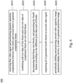
- FIG. 6 is a flow chart of a display method 600 of the projection display apparatus 100 according to some embodiments of the present disclosure.
- the display method 600 will be described with reference to the aforementioned projection display apparatus 100 and operations in the Figs. 2 to 5 .
- the first video signal 210 is received and the dynamic operation compensation between the first frame 211 and the second frame 212 is performed to generate a complement frame 230.
- the operation S610 can be understood with reference to the operation 200 of FIG. 2 , and thus the description will not be repeated.
- a new frame is inserted in every two consecutive image of the first video signal 210, in order to improve the continuity of the dynamic image. If frames per second of the video are more, the smoothness of the rendered dynamic image is better.
- the operation S620 can be understood with reference to the operation 300 of FIG. 3 , and thus the description will not be repeated here.
- the processing circuit 110 generates a third frame 320 by utilizing odd data in the first frame 211 and even row data in the complement frame 230, in order to extend the effect of the image continuity enhanced by the operation 200 of the previous dynamic operation compensation.
- the third frame 320 is decomposed into the plurality of blocks 410, 412, 414 and 416, and the fourth frames 420, 422, 424, and 426 are generated according to the different pixel data 1-4 of each of the plurality of blocks 410, 412, 414 and 416.
- the operation S630 can be understood with reference to FIG. 4 , and thus the description will not be repeated here.
- the second video signal 430 is periodically shifted and projected by the image projection display device 120, in order to generate the projection image.
- the operation of periodically shifting and projecting is to overlap the fast shifting projection of images with each other to form a single image by utilizing the visual persistence characteristics of the human eye, resulting in an effect of increasing the resolution.
- the second video signal 430 includes four fourth frames.
- the image projection display device 120 periodically shifts and projects the second video signal 430, and the four fourth frames are overlapped with each other and shown as one image with high resolution due to the visual persistence of the human eye.
- the resolution of the image can be increased to 8K with the above operation(s) and processing(s).
- the 4K resolution refers to a level at which the horizontal resolution of the display apparatus or display content reaches four thousand pixels, and the vertical resolution reaches two thousand pixels.
- the length and width of 4K videos are about 4096 ⁇ 2160 or 3840 ⁇ 2160.
- the length and width of 8K videos are about7680 ⁇ 4320.
- the total pixel size of the 8K specification is four times higher than the total pixel size of the 4K specification.
- 60Hz (hertz) in 4K60Hz represents the frame rate, i.e., a number of frames (images) are displayed per second. If more frames are displayed per second, the video will be smoother.
- control method 600 The multiple operations in the above control method 600 are only examples. It is not limited to be performed in the order in this example. Various operations of the display method 600 may be appropriately added, replaced, omitted, or performed in a different order, without departing from the scope of the appended claims.
- the projection display apparatus and the display method provided by the embodiments of the present disclosure can generate a higher resolution image by using a projection apparatus that supports lower native resolution.
Landscapes
- Engineering & Computer Science (AREA)
- Multimedia (AREA)
- Signal Processing (AREA)
- Physics & Mathematics (AREA)
- General Physics & Mathematics (AREA)
- Theoretical Computer Science (AREA)
- Computer Vision & Pattern Recognition (AREA)
- Computer Hardware Design (AREA)
- Transforming Electric Information Into Light Information (AREA)
- Controls And Circuits For Display Device (AREA)
- Projection Apparatus (AREA)
Claims (4)
- Projektionsanzeigevorrichtung (100), die Folgendes umfasst:einen Verarbeitungsschaltkreis (110), der so konfiguriert ist, dass er ein erstes Videosignal (210) als Eingangssignal der Projektionsanzeigevorrichtung (100) empfängt, wobei das erste Videosignal einen ersten Frame (211) und einen zweiten Frame (212) enthält,eine dynamische Operationskompensation gemäß dem ersten Frame (211) und dem zweiten Frame (212) in dem ersten Videosignal (210) auszuführen, um einen Komplementär-Frame (230) zwischen dem ersten Frame (211) und dem zweiten Frame (212) zu erzeugen,ungerade Zeilendaten (310, 314) des ersten Frames (211) und gerade Zeilendaten (312, 316) des Komplementär-Frames (230) zu verschachteln, um einen dritten Frame (320) zu erzeugen, wobei der erste Frame (211) und der zweite Frame (212) zwei aufeinanderfolgende Frames in dem ersten Videosignal (210) sind,den dritten Frame (320) zu zerlegen, um eine Vielzahl von vierten Frames (426, 424, 422, 420) zu erzeugen und die Vielzahl von vierten Frames als zweites Videosignal (SOUT, 430) auszugeben,wobei eine Spezifikation des ersten Videosignals (210) 8K60Hz beträgt und eine Spezifikation des zweiten Videosignals (430) 4K240Hz beträgt; undeine Bildprojektionsanzeigevorrichtung (120), die so konfiguriert ist, dass sie das zweite Videosignal (SOUT, 430) projiziert und anzeigt, wobei die Bildprojektionsanzeigevorrichtung (120) eine ursprüngliche Auflösung aufweist, die gleich der Auflösung des zweiten Videosignals (SOUT, 430) ist, und wobei die Bildprojektionsanzeigevorrichtung (120) ferner eine mehrachsige Verschiebevorrichtung (122) umfasst, die so konfiguriert ist, dass sie das zweite Videosignal (SOUT, 430) periodisch verschiebt und projiziert, um ein Projektionsbild (520) zu erzeugen;wobei die dynamische Operationskompensation eine Operation der Bewegungsschätzung und Bewegungskompensation ist, die mindestens eine der folgenden Operationen enthält: eine Deinterlacing-Operation und eine Bewegungsinterpolationsoperation, wobei die dynamische Operationskompensation so konfiguriert ist, dass sie den Komplementär-Frame (230) erzeugt und den Komplementär-Frame (230) zwischen dem ersten Frame (211) und dem zweiten Frame (212) des ersten Videosignals (210) einfügt, um die Kontinuität des dynamischen Bildes zu verbessern,wobei sowohl der erste Frame (211) als auch der Komplementär-Frame (230) eine Vielzahl von Datenzeilen umfassen, wobei jede der Vielzahl von Datenzeilen eine Vielzahl von Pixeldaten umfasst,wobei ungerade Datenzeilen des dritten Frames (320) jeweils aus ungeraden Datenzeilen des ersten Frames (211) gebildet werden und gerade Datenzeilen des dritten Frames (320) jeweils aus geraden Datenzeilen des Komplementär-Frames (230) gebildet werden,wobei der Verarbeitungsschaltkreis (110) so konfiguriert ist, dass er die Vielzahl von Pixeldaten des dritten Frames (320) in eine Vielzahl von Blöcken (410, 412, 414, 416) zerlegt, die jeweils vier Pixeldaten umfassen, die gemäß einer vorbestimmten Richtung angeordnet sind, und die vierten Frames (426, 424, 422, 420) gemäß den entsprechenden Pixeldaten von jedem der Blöcke erzeugt,wobei ein erster der Vielzahl von vierten Frames (420) gemäß ersten Pixeldaten (1) in jedem der Vielzahl von Blöcken erzeugt wird, ein zweiter der Vielzahl von vierten Frames (422) gemäß zweiten Pixeldaten (2) in jedem der Vielzahl von Blöcken erzeugt wird, ein dritter der Vielzahl von vierten Frames (424) gemäß dritten Pixeldaten (3) in jedem der Vielzahl von Blöcken erzeugt wird und ein vierter der Vielzahl von vierten Frames (426) gemäß vierten Pixeldaten (4) in jedem der Vielzahl von Blöcken erzeugt wird,wobei eine Auflösung und eine Frame-Rate des ersten Videosignals (210) 8K bzw. 60 Hz betragen, eine Auflösung und eine Frame-Rate des Komplementär-Frames (230) 8K bzw. 120 Hz betragen, eine Auflösung und eine Frame-Rate des dritten Frames (320) 8K bzw. 60 Hz betragen und eine Auflösung und eine Frame-Rate von jedem der vierten Frames (426, 424, 422, 420) und des zweiten Videosignals (430) 4K bzw. 240 Hz betragen.
- Projektionsanzeigevorrichtung (100) nach Anspruch 1, wobei die verschiedenen Pixeldaten in jedem der Vielzahl von Blöcken im Uhrzeigersinn angeordnet sind.
- Anzeigeverfahren (600) zum Betreiben der Projektionsanzeigevorrichtung nach Anspruch 1, das Folgendes umfasst:Empfangen eines ersten Videosignals (210) als Eingangssignal der Projektionsanzeigevorrichtung (100), wobei das erste Videosignal einen ersten Frame (211) und einen zweiten Frame (212) enthält;Ausführen einer dynamischen Operationskompensation an dem ersten Frame (211) und dem zweiten Frame (212) in dem ersten Videosignal (210), um einen Komplementär-Frame (230) zwischen dem ersten Frame (211) und dem zweiten Frame (212) zu erzeugen,Kombinieren des ersten Frames (211) und des Komplementär-Frames (230), um einen dritten Frame (320) zu erzeugen, wobei der dritte Frame (320) aus ungeraden Zeilendaten (310, 314) des ersten Frames (211) und Zeilendaten (312, 316) des Komplementär-Frames (230) erzeugt wird, die miteinander verschachtelt sind,wobei der erste Frame (211) und der zweite Frame (212) zwei aufeinanderfolgende Frames in dem ersten Videosignal (210) sind;Zerlegen des dritten Frames (320), um eine Vielzahl von vierten Frames (420, 422, 424, 426) zu erzeugen, und Ausgeben der Vielzahl von vierten Frames als zweites Videosignal (SOUT, 430), wobei eine Spezifikation des ersten Videosignals (210) 8K60Hz beträgt und eine Spezifikation des zweiten Videosignals (430) 4K240Hz beträgt; undAnzeigen des zweiten Videosignals (SOUT, 430) durch eine Bildprojektionsanzeigevorrichtung (120) durch periodisches Verschieben und Projizieren des zweiten Videosignals (SOUT, 430) und Erzeugen eines Proiektionsbildes (520),wobei die dynamische Operationskompensation eine Operation der Bewegungsschätzung und Bewegungskompensation ist, die mindestens eine der folgenden Operationen enthält: eine Deinterlacing-Operation und eine Bewegungsinterpolationsoperation, wobei die dynamische Operationskompensation so konfiguriert ist, dass sie den Komplementär-Frame (230) erzeugt und den Komplementär-Frame (230) zwischen dem ersten Frame (211) und dem zweiten Frame (212) des ersten Videosignals (210) einfügt, um die Kontinuität des dynamischen Bildes zu verbessern,wobei sowohl der erste Frame (211) als auch der Komplementär-Frame (230) eine Vielzahl von Datenzeilen umfassen, wobei jede der Vielzahl von Datenzeilen eine Vielzahl von Pixeldaten umfasst,wobei ungerade Datenzeilen des dritten Frames (320) jeweils aus ungeraden Datenzeilen des ersten Frames (211) gebildet werden und gerade Datenzeilen des dritten Frames (320) jeweils aus geraden Datenzeilen des Komplementär-Frames (230) gebildet werden,wobei das Zerlegen des dritten Frames das Zerlegen der Vielzahl von Pixeldaten des dritten Frames (320) in eine Vielzahl von Blöcken (410, 412, 414, 416), die jeweils vier Pixeldaten umfassen, die gemäß einer vorbestimmten Richtung angeordnet sind, und das Erzeugen der vierten Frames (426, 424, 422, 420) gemäß den entsprechenden Pixeldaten von jedem der Vielzahl von Blöcken umfasst,wobei ein erster der Vielzahl von vierten Frames (420) gemäß ersten Pixeldaten (1) in jedem der Vielzahl von Blöcken erzeugt wird, ein zweiter der Vielzahl von vierten Frames (422) gemäß zweiten Pixeldaten (2) in jedem der Vielzahl von Blöcken erzeugt wird, ein dritter der Vielzahl von vierten Frames (424) gemäß dritten Pixeldaten (3) in jedem der Vielzahl von Blöcken erzeugt wird und ein vierter der Vielzahl von vierten Frames (426) gemäß vierten Pixeldaten (4) in jedem der Vielzahl von Blöcken erzeugt wird;wobei eine Auflösung und eine Frame-Rate des ersten Videosignals (210) 8K bzw. 60 Hz betragen, eine Auflösung und eine Frame-Rate des Komplementär-Frames (230) 8K bzw. 120 Hz betragen, eine Auflösung und eine Frame-Rate des dritten Frames (320) 8K bzw. 60 Hz betragen und eine Auflösung und eine Frame-Rate von sowohl den vierten Frames (426, 424, 422, 420) als auch dem zweiten Videosignal (430) 4K bzw. 240 Hz betragen.
- Anzeigeverfahren (600) nach Anspruch 3, wobei die verschiedenen Pixeldaten in jedem der Vielzahl von Blöcken im Uhrzeigersinn angeordnet sind.
Applications Claiming Priority (1)
| Application Number | Priority Date | Filing Date | Title |
|---|---|---|---|
| CN201910133086.8A CN111614945B (zh) | 2019-02-22 | 2019-02-22 | 投影显示设备与显示方法 |
Publications (3)
| Publication Number | Publication Date |
|---|---|
| EP3699896A1 EP3699896A1 (de) | 2020-08-26 |
| EP3699896B1 true EP3699896B1 (de) | 2024-11-27 |
| EP3699896C0 EP3699896C0 (de) | 2024-11-27 |
Family
ID=67137735
Family Applications (1)
| Application Number | Title | Priority Date | Filing Date |
|---|---|---|---|
| EP19183428.2A Active EP3699896B1 (de) | 2019-02-22 | 2019-06-28 | Projektionsanzeigevorrichtung und projektionsanzeigeverfahren |
Country Status (4)
| Country | Link |
|---|---|
| US (1) | US11044438B2 (de) |
| EP (1) | EP3699896B1 (de) |
| JP (1) | JP6770142B2 (de) |
| CN (1) | CN111614945B (de) |
Families Citing this family (3)
| Publication number | Priority date | Publication date | Assignee | Title |
|---|---|---|---|---|
| CN110431616B (zh) * | 2019-06-21 | 2024-04-19 | 京东方科技集团股份有限公司 | 图片帧显示设备和显示方法 |
| US11605328B2 (en) * | 2020-09-16 | 2023-03-14 | Aiconnx Technology Corporation | Split-type display system |
| KR20230170790A (ko) * | 2021-04-23 | 2023-12-19 | 아발론 홀로그래픽스 인크. | 직접 투사 다중 광 필드 디스플레이 |
Citations (3)
| Publication number | Priority date | Publication date | Assignee | Title |
|---|---|---|---|---|
| US20080284763A1 (en) * | 2007-05-16 | 2008-11-20 | Mitsubishi Electric Corporation | Image display apparatus and method, and image generating apparatus and method |
| US20100053429A1 (en) * | 2008-08-26 | 2010-03-04 | Sony Corporation | Picture signal processing unit, image display unit, and picture signal processing method |
| US20140340492A1 (en) * | 2013-05-20 | 2014-11-20 | Panasonic Corporation | Projection display apparatus |
Family Cites Families (9)
| Publication number | Priority date | Publication date | Assignee | Title |
|---|---|---|---|---|
| JP4479763B2 (ja) * | 2007-08-31 | 2010-06-09 | ソニー株式会社 | 投射型表示装置および投射表示制御プログラム |
| US8958484B2 (en) | 2009-08-11 | 2015-02-17 | Google Inc. | Enhanced image and video super-resolution processing |
| CN103108148B (zh) | 2011-11-14 | 2016-03-30 | 联想(北京)有限公司 | 视频帧的插帧方法以及信息处理设备 |
| CN103813180A (zh) | 2014-02-11 | 2014-05-21 | 广州中大数字家庭工程技术研究中心有限公司 | 一种自适应显示设备的媒体分辨率变换方法 |
| JP6364609B2 (ja) * | 2014-03-17 | 2018-08-01 | パナソニックIpマネジメント株式会社 | 投写型画像表示装置、及び画像信号生成装置 |
| US10091477B2 (en) * | 2015-07-16 | 2018-10-02 | Panasonic Intellectual Property Management Co., Ltd. | Projection image display apparatus |
| US9736442B1 (en) | 2016-08-29 | 2017-08-15 | Christie Digital Systems Usa, Inc. | Device, system and method for content-adaptive resolution-enhancement |
| TWI624804B (zh) | 2016-11-07 | 2018-05-21 | 盾心科技股份有限公司 | 利用超解析重建法生成高解析度影像的方法與系統 |
| CN106507075A (zh) * | 2016-11-18 | 2017-03-15 | 海信集团有限公司 | 一种投影图像处理方法、装置及投影显示系统 |
-
2019
- 2019-02-22 CN CN201910133086.8A patent/CN111614945B/zh active Active
- 2019-06-27 US US16/455,729 patent/US11044438B2/en active Active
- 2019-06-28 JP JP2019120978A patent/JP6770142B2/ja active Active
- 2019-06-28 EP EP19183428.2A patent/EP3699896B1/de active Active
Patent Citations (3)
| Publication number | Priority date | Publication date | Assignee | Title |
|---|---|---|---|---|
| US20080284763A1 (en) * | 2007-05-16 | 2008-11-20 | Mitsubishi Electric Corporation | Image display apparatus and method, and image generating apparatus and method |
| US20100053429A1 (en) * | 2008-08-26 | 2010-03-04 | Sony Corporation | Picture signal processing unit, image display unit, and picture signal processing method |
| US20140340492A1 (en) * | 2013-05-20 | 2014-11-20 | Panasonic Corporation | Projection display apparatus |
Also Published As
| Publication number | Publication date |
|---|---|
| US11044438B2 (en) | 2021-06-22 |
| JP6770142B2 (ja) | 2020-10-14 |
| CN111614945A (zh) | 2020-09-01 |
| EP3699896A1 (de) | 2020-08-26 |
| JP2020137107A (ja) | 2020-08-31 |
| CN111614945B (zh) | 2022-02-08 |
| US20200275051A1 (en) | 2020-08-27 |
| EP3699896C0 (de) | 2024-11-27 |
Similar Documents
| Publication | Publication Date | Title |
|---|---|---|
| CN109803175B (zh) | 视频处理方法及装置、设备、存储介质 | |
| CN108364623B (zh) | 信息处理设备、信息处理方法和计算机可读介质 | |
| US6906687B2 (en) | Digital formatter for 3-dimensional display applications | |
| JP4777675B2 (ja) | 画像処理装置、画像表示装置、画像処理方法、その方法をコンピュータに実行させるプログラム、および記録媒体 | |
| EP3699896B1 (de) | Projektionsanzeigevorrichtung und projektionsanzeigeverfahren | |
| TW200816812A (en) | Image display apparatus, signal processing apparatus, image display method, and computer program product | |
| TWI455572B (zh) | 用於立體顯示之圖框率轉換裝置及方法 | |
| US20150222890A1 (en) | Dual-channel three-dimension projector | |
| JP2005286677A (ja) | 撮像装置 | |
| JP2011166705A (ja) | 映像処理装置、映像処理方法 | |
| JP5051983B2 (ja) | フレームレート制御によるlcdぼけ低減 | |
| US9100637B2 (en) | Image processing apparatus and control method thereof | |
| US20120120191A1 (en) | Image processor for use in a frame sequential 3d display system and related 3d display system | |
| EP3941036B1 (de) | Verfahren, elektronische vorrichtung und speichermedium zur auswahl eines referenzrahmens | |
| US8330799B2 (en) | Image output apparatus and image output method | |
| US10192508B2 (en) | Display apparatus and three-dimensional image display system | |
| TWI698119B (zh) | 投影顯示設備與顯示方法 | |
| WO2014115522A1 (ja) | フレームレート変換装置及びフレームレート変換方法並びにフレームレート変換装置を備えた表示装置及び撮像装置 | |
| JP5700998B2 (ja) | 立体映像表示装置及びその制御方法 | |
| JP4489760B2 (ja) | 3dビデオ信号を生成する装置 | |
| TWI288393B (en) | Signal processing apparatus and image output apparatus | |
| US8878837B2 (en) | Image processing apparatus having on-screen display function and method thereof | |
| EP0568320B1 (de) | Bildvorführungsanlage und -verfahren | |
| JP2017102190A (ja) | 表示装置及びその制御方法 | |
| JP2007288483A (ja) | 画像変換装置 |
Legal Events
| Date | Code | Title | Description |
|---|---|---|---|
| PUAI | Public reference made under article 153(3) epc to a published international application that has entered the european phase |
Free format text: ORIGINAL CODE: 0009012 |
|
| STAA | Information on the status of an ep patent application or granted ep patent |
Free format text: STATUS: THE APPLICATION HAS BEEN PUBLISHED |
|
| AK | Designated contracting states |
Kind code of ref document: A1 Designated state(s): AL AT BE BG CH CY CZ DE DK EE ES FI FR GB GR HR HU IE IS IT LI LT LU LV MC MK MT NL NO PL PT RO RS SE SI SK SM TR |
|
| AX | Request for extension of the european patent |
Extension state: BA ME |
|
| STAA | Information on the status of an ep patent application or granted ep patent |
Free format text: STATUS: REQUEST FOR EXAMINATION WAS MADE |
|
| 17P | Request for examination filed |
Effective date: 20200924 |
|
| RBV | Designated contracting states (corrected) |
Designated state(s): AL AT BE BG CH CY CZ DE DK EE ES FI FR GB GR HR HU IE IS IT LI LT LU LV MC MK MT NL NO PL PT RO RS SE SI SK SM TR |
|
| STAA | Information on the status of an ep patent application or granted ep patent |
Free format text: STATUS: EXAMINATION IS IN PROGRESS |
|
| 17Q | First examination report despatched |
Effective date: 20211011 |
|
| 17Q | First examination report despatched |
Effective date: 20211022 |
|
| GRAP | Despatch of communication of intention to grant a patent |
Free format text: ORIGINAL CODE: EPIDOSNIGR1 |
|
| STAA | Information on the status of an ep patent application or granted ep patent |
Free format text: STATUS: GRANT OF PATENT IS INTENDED |
|
| INTG | Intention to grant announced |
Effective date: 20240604 |
|
| GRAS | Grant fee paid |
Free format text: ORIGINAL CODE: EPIDOSNIGR3 |
|
| GRAA | (expected) grant |
Free format text: ORIGINAL CODE: 0009210 |
|
| STAA | Information on the status of an ep patent application or granted ep patent |
Free format text: STATUS: THE PATENT HAS BEEN GRANTED |
|
| AK | Designated contracting states |
Kind code of ref document: B1 Designated state(s): AL AT BE BG CH CY CZ DE DK EE ES FI FR GB GR HR HU IE IS IT LI LT LU LV MC MK MT NL NO PL PT RO RS SE SI SK SM TR |
|
| REG | Reference to a national code |
Ref country code: GB Ref legal event code: FG4D |
|
| REG | Reference to a national code |
Ref country code: CH Ref legal event code: EP |
|
| REG | Reference to a national code |
Ref country code: IE Ref legal event code: FG4D |
|
| REG | Reference to a national code |
Ref country code: DE Ref legal event code: R096 Ref document number: 602019062487 Country of ref document: DE |
|
| U01 | Request for unitary effect filed |
Effective date: 20241212 |
|
| U07 | Unitary effect registered |
Designated state(s): AT BE BG DE DK EE FI FR IT LT LU LV MT NL PT RO SE SI Effective date: 20250102 |
|
| PG25 | Lapsed in a contracting state [announced via postgrant information from national office to epo] |
Ref country code: IS Free format text: LAPSE BECAUSE OF FAILURE TO SUBMIT A TRANSLATION OF THE DESCRIPTION OR TO PAY THE FEE WITHIN THE PRESCRIBED TIME-LIMIT Effective date: 20250327 Ref country code: HR Free format text: LAPSE BECAUSE OF FAILURE TO SUBMIT A TRANSLATION OF THE DESCRIPTION OR TO PAY THE FEE WITHIN THE PRESCRIBED TIME-LIMIT Effective date: 20241127 |
|
| PG25 | Lapsed in a contracting state [announced via postgrant information from national office to epo] |
Ref country code: ES Free format text: LAPSE BECAUSE OF FAILURE TO SUBMIT A TRANSLATION OF THE DESCRIPTION OR TO PAY THE FEE WITHIN THE PRESCRIBED TIME-LIMIT Effective date: 20241127 |
|
| PG25 | Lapsed in a contracting state [announced via postgrant information from national office to epo] |
Ref country code: NO Free format text: LAPSE BECAUSE OF FAILURE TO SUBMIT A TRANSLATION OF THE DESCRIPTION OR TO PAY THE FEE WITHIN THE PRESCRIBED TIME-LIMIT Effective date: 20250227 |
|
| PG25 | Lapsed in a contracting state [announced via postgrant information from national office to epo] |
Ref country code: GR Free format text: LAPSE BECAUSE OF FAILURE TO SUBMIT A TRANSLATION OF THE DESCRIPTION OR TO PAY THE FEE WITHIN THE PRESCRIBED TIME-LIMIT Effective date: 20250228 |
|
| PG25 | Lapsed in a contracting state [announced via postgrant information from national office to epo] |
Ref country code: PL Free format text: LAPSE BECAUSE OF FAILURE TO SUBMIT A TRANSLATION OF THE DESCRIPTION OR TO PAY THE FEE WITHIN THE PRESCRIBED TIME-LIMIT Effective date: 20241127 |
|
| PG25 | Lapsed in a contracting state [announced via postgrant information from national office to epo] |
Ref country code: RS Free format text: LAPSE BECAUSE OF FAILURE TO SUBMIT A TRANSLATION OF THE DESCRIPTION OR TO PAY THE FEE WITHIN THE PRESCRIBED TIME-LIMIT Effective date: 20250227 |
|
| U20 | Renewal fee for the european patent with unitary effect paid |
Year of fee payment: 7 Effective date: 20250509 |
|
| PG25 | Lapsed in a contracting state [announced via postgrant information from national office to epo] |
Ref country code: SM Free format text: LAPSE BECAUSE OF FAILURE TO SUBMIT A TRANSLATION OF THE DESCRIPTION OR TO PAY THE FEE WITHIN THE PRESCRIBED TIME-LIMIT Effective date: 20241127 |
|
| PGFP | Annual fee paid to national office [announced via postgrant information from national office to epo] |
Ref country code: GB Payment date: 20250401 Year of fee payment: 7 |
|
| PG25 | Lapsed in a contracting state [announced via postgrant information from national office to epo] |
Ref country code: SK Free format text: LAPSE BECAUSE OF FAILURE TO SUBMIT A TRANSLATION OF THE DESCRIPTION OR TO PAY THE FEE WITHIN THE PRESCRIBED TIME-LIMIT Effective date: 20241127 |
|
| PG25 | Lapsed in a contracting state [announced via postgrant information from national office to epo] |
Ref country code: CZ Free format text: LAPSE BECAUSE OF FAILURE TO SUBMIT A TRANSLATION OF THE DESCRIPTION OR TO PAY THE FEE WITHIN THE PRESCRIBED TIME-LIMIT Effective date: 20241127 |
|
| PLBE | No opposition filed within time limit |
Free format text: ORIGINAL CODE: 0009261 |
|
| STAA | Information on the status of an ep patent application or granted ep patent |
Free format text: STATUS: NO OPPOSITION FILED WITHIN TIME LIMIT |
|
| REG | Reference to a national code |
Ref country code: CH Ref legal event code: L10 Free format text: ST27 STATUS EVENT CODE: U-0-0-L10-L00 (AS PROVIDED BY THE NATIONAL OFFICE) Effective date: 20251008 |
|
| 26N | No opposition filed |
Effective date: 20250828 |
|
| REG | Reference to a national code |
Ref country code: CH Ref legal event code: H13 Free format text: ST27 STATUS EVENT CODE: U-0-0-H10-H13 (AS PROVIDED BY THE NATIONAL OFFICE) Effective date: 20260127 |
|
| PG25 | Lapsed in a contracting state [announced via postgrant information from national office to epo] |
Ref country code: MC Free format text: LAPSE BECAUSE OF FAILURE TO SUBMIT A TRANSLATION OF THE DESCRIPTION OR TO PAY THE FEE WITHIN THE PRESCRIBED TIME-LIMIT Effective date: 20241127 |
|
| PG25 | Lapsed in a contracting state [announced via postgrant information from national office to epo] |
Ref country code: IE Free format text: LAPSE BECAUSE OF NON-PAYMENT OF DUE FEES Effective date: 20250628 |
|
| PG25 | Lapsed in a contracting state [announced via postgrant information from national office to epo] |
Ref country code: CH Free format text: LAPSE BECAUSE OF NON-PAYMENT OF DUE FEES Effective date: 20250630 |