EP3700170A1 - Vorrichtung und verfahren zum übertragen von identifikations- und/oder datenflusssteuerungsinformationen zwischen vorrichtungen - Google Patents
Vorrichtung und verfahren zum übertragen von identifikations- und/oder datenflusssteuerungsinformationen zwischen vorrichtungen Download PDFInfo
- Publication number
- EP3700170A1 EP3700170A1 EP19158670.0A EP19158670A EP3700170A1 EP 3700170 A1 EP3700170 A1 EP 3700170A1 EP 19158670 A EP19158670 A EP 19158670A EP 3700170 A1 EP3700170 A1 EP 3700170A1
- Authority
- EP
- European Patent Office
- Prior art keywords
- packet
- field
- data flow
- flow control
- control
- Prior art date
- Legal status (The legal status is an assumption and is not a legal conclusion. Google has not performed a legal analysis and makes no representation as to the accuracy of the status listed.)
- Pending
Links
Images



Classifications
-
- H—ELECTRICITY
- H04—ELECTRIC COMMUNICATION TECHNIQUE
- H04L—TRANSMISSION OF DIGITAL INFORMATION, e.g. TELEGRAPHIC COMMUNICATION
- H04L69/00—Network arrangements, protocols or services independent of the application payload and not provided for in the other groups of this subclass
- H04L69/30—Definitions, standards or architectural aspects of layered protocol stacks
- H04L69/32—Architecture of open systems interconnection [OSI] 7-layer type protocol stacks, e.g. the interfaces between the data link level and the physical level
- H04L69/322—Intralayer communication protocols among peer entities or protocol data unit [PDU] definitions
- H04L69/324—Intralayer communication protocols among peer entities or protocol data unit [PDU] definitions in the data link layer [OSI layer 2], e.g. HDLC
-
- H—ELECTRICITY
- H04—ELECTRIC COMMUNICATION TECHNIQUE
- H04L—TRANSMISSION OF DIGITAL INFORMATION, e.g. TELEGRAPHIC COMMUNICATION
- H04L47/00—Traffic control in data switching networks
- H04L47/10—Flow control; Congestion control
- H04L47/24—Traffic characterised by specific attributes, e.g. priority or QoS
- H04L47/2441—Traffic characterised by specific attributes, e.g. priority or QoS relying on flow classification, e.g. using integrated services [IntServ]
-
- H—ELECTRICITY
- H04—ELECTRIC COMMUNICATION TECHNIQUE
- H04L—TRANSMISSION OF DIGITAL INFORMATION, e.g. TELEGRAPHIC COMMUNICATION
- H04L47/00—Traffic control in data switching networks
- H04L47/10—Flow control; Congestion control
- H04L47/36—Flow control; Congestion control by determining packet size, e.g. maximum transfer unit [MTU]
- H04L47/365—Dynamic adaptation of the packet size
-
- H—ELECTRICITY
- H04—ELECTRIC COMMUNICATION TECHNIQUE
- H04L—TRANSMISSION OF DIGITAL INFORMATION, e.g. TELEGRAPHIC COMMUNICATION
- H04L69/00—Network arrangements, protocols or services independent of the application payload and not provided for in the other groups of this subclass
- H04L69/22—Parsing or analysis of headers
Definitions
- Examples relate to a mechanism for interfacing between devices, more particularly a device and method for transferring identification and/or data flow control information between link partner devices.
- ITU-T G.999.1 defines an interface between a link layer and a physical layer for digital subscriber lines (DSL) transceivers.
- the interface defined in ITU-T G.999.1 is a single point-to-point interconnection between a link layer device and a physical layer device.
- an identification of a packet or a fragment of the packet, and data flow control information are carried between the link layer and the physical layer.
- the interface defined in ITU-T 999.1 adds an additional tag, an Ethernet encapsulation header, and an additional frame check sequence (FCS) to each packet or fragment.
- FCS frame check sequence
- the interface defined in ITU-T 999.1 also inserts a pause frame to carry data flow control information.
- Examples are disclosed for a mechanism to transfer identification, priority information, and/or data flow control information without overhead in the interface between two link partner devices (e.g. a link layer device and a physical layer device).
- link partner devices e.g. a link layer device and a physical layer device.
- Fig. 1 shows the reference model defined in ITU.T G.999.1 for the interface between a link layer 102 and a physical layer 104.
- the ITU.T G.999.1 specification is incorporated herein as if fully set forth.
- Multiple streams (N streams) are supported between the link layer 102 and the physical layer 104.
- Stream(n).confirm is a primitive used by the link layer 102 to pass one or more packets to the physical layer 104 to be transported.
- a packet is a block of data consisting of a certain number of octets for transport between a physical layer port and a link layer port.
- the fragmentation function 112 may divide a packet to multiple fragments if the size of the packet exceeds the maximum fragment size. If the length of the packet is less than or equal to the maximum fragment size, the packet is transmitted without fragmentation.
- the tag function 114 adds an identification tag to each packet or fragment of a packet.
- the identification tag is inserted into a tag control identification (TCI) field (16 bits).
- TCI field includes a start of fragment (SoF) bit (1 bit), an end of fragment (EoF) bit (1 bit), a data stream flag (1 bit), and a stream identification (SID) (13 bits).
- SoF start of fragment
- EoF end of fragment
- SID stream identification
- the tag function may add a length field to indicate the number of bytes in a packet/fragment.
- the tagged packets or fragments on multiple streams are multiplexed by a multiplexer 116.
- the Ethernet (ETH) adaptation block 118 adds fields to the tagged packets or fragments for compliance with the IEEE 802.3 format.
- the Ethernet adaptation block 118 adds a source medium access control (MAC) address field, a destination MAC address field, and a virtual local area network (LAN) tag protocol identifier (TPID) field to the tagged packets/fragments.
- the Ethernet adaptation block 118 may also append a padding field.
- the frame check sequence (FCS) block 120 adds an FCS field for error detection.
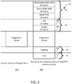
- Fig. 2A shows a packet/fragment format without overhead, (i.e. without any Ethernet header or tag).
- Fig. 2B shows a packet/fragment format with overhead.
- the Ethernet header 202 and the padding 208, the TCI field 204, the length field 206, and the FCS field 210 are all additional overheads.
- the tagged data packet or fragment is sent to the physical layer 104.
- the packets/fragments are demultiplexed for each stream by the demultiplexer 122.
- the decapsulation function 124 recovers the packets by performing the reverse functions (e.g. error verification and removal of the FCS field, removal of the Ethernet header fields, removal of the identification tag, and reassembly of fragments to a packet).
- the packet transfer functions described above may also be implemented for transfer of packets from the physical layer 104 to the link layer 102.
- the fragment function 132, the tagging function 134, the Ethernet function 136, and the FCS function 138 as explained above are performed in the physical layer, and the decapsulation function 140 is performed in the link layer 102.
- Data flow control is a mechanism that prevents congestion by ensuring that a transmitting device does not overwhelm a receiving device with data.
- the physical layer 104 may send a pause frame to the link layer 102.
- Data flow control is implemented through a single pause frame containing the data flow states of all streams between the link layer 102 and the physical layer 104.
- the DFC field contains N bits, where N represents the number of streams.
- a data flow control bit is set to '0' to request to stop transmission and set to '1' to request to resume transmission for the respective data stream.
- An Ethernet header is also added to the pause frame.
- the identification of a packet or a fragment of a packet may be carried in a packet control header (PCH) attached to each packet or fragment.
- the data flow control information may be carried in the PCH attached to each data frame or fragment or an idle frame to eliminate the pause frame insertion.
- priority information of the packet or fragment may be carried in the PCH of each frame/fragment to control quality of service (QoS) for the data packets.
- QoS quality of service
- the identification information, the data flow control information, and the priority information, or any other information may be carried in the PCH independently.
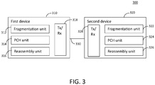
- Fig. 3 is a block diagram of an example system in accordance with one example.
- the system 300 includes a first device 310 and a second device 320 that are connected over a connection 330.
- the first device 310 may be a link layer device and the second device 320 may be a physical layer device, or vice versa.
- the link layer device may be an Ethernet switch, router, gateway, or the like, and the physical layer device may be a DSL physical layer chip.
- the first and second devices 310, 320 may be directly connected e.g. via a point-to-point connection between the devices 310, 320.
- the examples disclosed herein may be implemented if the network component(s) in the middle also supports the mechanism disclosed herein.
- the first and second devices 310, 320 are link partner devices in communication.
- a link partner device is a device in direct communication over a link established therebetween.
- the devices may be a physical layer device or a link layer device.
- the communication may be between two physical layer devices, between two link layer devices, or between a physical layer device and a link layer device.
- Devices 310, 320 may support multiple streams simultaneously and identification information for packets or fragments of the packets and/or data flow control information may be transferred between the first device 310 and the second device 320.
- Each device 310, 320 includes a fragmentation unit 312, 322, a PCH unit 314, 324, a reassembly unit 316, 326, and a transceiver 318, 328, respectively.
- the fragmentation unit 312, 322 is configured to fragment a packet into multiple fragments if a size of the packet is greater than a maximum fragment size. If the size of the packet is not greater than the maximum fragment size, the packet may not be fragmented.
- the PCH unit 314, 324 is configured to generate a PCH for a packet or each fragment of the packet.
- the PCH may include at least one of a traffic control identifier field for identifying a data stream to which the packet belongs, a priority field for indicating a priority for the packet, or a data flow control field for congestion control between the devices 310, 320.
- the PCH may include any other information.
- the reassembly unit 316, 326 may reassemble fragments to a packet based on the information carried in the PCH.
- the transceiver 318, 328 is configured to send the packet or the fragments of the packet with the PCH via a connection 330 between the devices 310, 320.
- the transceiver 318, 328 may be configured to send the PCH in place of a preamble for bit-level synchronization at the link partner device.
- the PCH may include a start of packet (SOP) field, a packet type field, an extension field type field, and an extension field, which will be explained in detail below.
- SOP start of packet
- the traffic control identifier field, the priority field, and the data flow control field may be inserted into the extension field in the PCH.
- the packet type field may be set to a predetermined value to indicate that the packet or the fragment is sent with the PCH.
- the data flow control field may include a first set of bits for indicating a group index of a data stream and a second set of bits for data flow control information for a group of data streams corresponding to the group index.
- the data flow control field may be sent in a round robin way for multiple groups of streams.
- Fig. 4A shows a format of a conventional packet transferred between two devices.
- a data frame (packet data) 420 is preceded by a preamble 410 (8 bytes).
- the preamble 410 includes a start of packet (SOP) 412, a pattern 414 of alternating 1s and 0s for allowing devices on the network to synchronize their receiver clocks and bit-level synchronization, and a start frame delimiter (SFD) 416.
- SFD 416 is designed to break the bit pattern of the preamble and signal the start of the packet data.
- Fig. 4B shows an example format of a packet or fragment transferred between devices 310, 320 in accordance with one example.
- the packet/fragment includes a PCH 450 and a packet data 460.
- the PCH 450 may be 8-bytes long, or alternatively any length may be used.
- the transmitting device e.g. either a link layer device or a physical layer device
- the PCH 450 may include an SOP field 451, a packet type field 452, a sub-port ID field 453, an extension field type field 454, an extension field 455, and a cyclic redundancy check (CRC) 456.
- the SOP field 451 may be set to a fixed value (e.g. 0xFB).
- the packet type field 452 (e.g. 2 bits) indicates the type of the packet.
- the packet type field 452 may be set as follows: 00: Ethernet packet with packet specific information (e.g. the packet format as shown in Fig. 4B ), 01: Ethernet packet without packet specific information (compatible with the preamble format shown in Fig. 4A ), 10: idle packet with status, and 11: reserved.
- the extension field type field 454 (e.g. 2 bits) indicates the type of the extension field 455.
- the extension field type field 454 may be set as follows: 00: ignore the extension field, 01: the extension field carries time stamp, 10: user-defined information type 1 (as an example), and 11:user-defined information type 2 (as an example).
- the extension field 455 (e.g. 40 bits) carries data defined by the extension field type field 454, (e.g. time stamp).
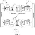
- FIG. 5 shows the reference model for the interface between a link layer device and a physical layer device in accordance with one example.
- a link layer device 502 may pass a data packet to a physical layer device 504, or vice versa.
- the link layer device 502 and the physical layer device 504 may support a plurality of streams simultaneously.
- a packet is a block of data consisting of a certain number of octets for transport between a physical layer port and a link layer port.
- the fragmentation function 512 in the link layer device 502 may divide the packet to multiple fragments if the size of the packet exceeds the maximum fragment size. If the length of the packet is less than or equal to the maximum fragment size, the packet may be transmitted without fragmentation.
- Data packets on the plurality of streams are multiplexed by the multiplexer 514.
- the PCH function 516 generates, and appends, a PCH to each packet or fragment of the packet. An example structure of the PCH is shown in Fig. 4B .
- the PCH function 516 may add in the extension field 455 of the PCH at least one of a TCI field, a priority field, and/or a DFC field, or any additional information.
- the TCI field may include a start of fragment (SoF) field (1 bit), an end of fragment (EoF) field (1 bit), and a stream identification (SID) field (e.g. 10 bits to support 1024 streams between the link layer device 502 and the physical layer device 504).
- SoF start of fragment
- EoF end of fragment
- SID stream identification
- the extension field type field 454 in the PCH may be set to "10" or "11" to indicate that the packet is transmitted with the PCH. Alternatively, the extension field type field 454 may be set to a different value that is mutually agreed with between the devices 502, 504.
- the priority field may indicate a priority of the packet/fragment (e.g. 3 bits) for QoS control.
- the DFC field may be included in the PCH for controlling data flow from the physical layer device 504 to the link layer device 502. Alternatively, the data flow control for the data flow from the physical layer device 504 to the link layer device 502 may not be implemented.
- the link layer device 502 sends a packet or fragment with the PCH to the physical layer device 504. If there is no data packet to be transferred and DFC information is changed for any stream, an idle packet (a packet without payload data) with DFC carried in the PCH may be generated and transferred between the devices 502, 504.
- the packets/fragments on multiple streams are demultiplexed by the demultiplexer 518.
- the reassembly unit 520 of the physical layer device 504 reassembles fragments to a packet based on the TCI field in the PCH.
- the fragmentation function 522 in the physical layer device 504 may divide the packet to multiple fragments if the size of the packet exceeds the maximum fragment size. If the length of the packet is less than or equal to the maximum fragment size, the packet may be transmitted without fragmentation.
- Data packets on the plurality of streams are multiplexed by the multiplexer 524.
- the PCH function 526 in the physical layer device 504 generates, and appends, a PCH to each packet or fragment of the packet. An example structure of the PCH is shown in Fig. 4B .
- the PCH function 526 may add in the extension field 455 of the PCH at least one of a TCI field, a priority field, and/or a DFC field, or any additional information.
- the TCI field may include an SoF field (1 bit), an EoF field (1 bit), and an SID field (e.g. 10 bits to support 1024 streams between the link layer device 502 and the physical layer device 504).
- the extension field type field 454 in the PCH may be set to "10" or "11" to indicate that the packet is transmitted with the PCH. Alternatively, the extension field type field 454 may be set to a different value that is mutually agreed with between the devices 502, 504.
- the priority field may indicate a priority of the packet/fragment (e.g.
- the DFC field may be included in the PCH for controlling data flow from the link layer device 502 to the physical layer device 504.
- the physical layer device 504 sends a packet or fragment with the PCH to the link layer device 502. If there is no data packet to be transferred and DFC information is changed for any stream, an idle packet with DFC carried in the PCH may be generated and transferred between the devices 502, 504.
- the packets/fragments on multiple streams are demultiplexed by the demultiplexer 528.
- the reassembly unit 530 of the link layer device 502 reassembles fragments to a packet based on the TCI field in the PCH.
- the examples disclosed herein do not require a separate identification tag, Ethernet header encapsulation, FCS generation and insertion, and the corresponding reverse actions in a link partner device.
- the examples do not require separate pause frame generation and insertion, and the corresponding reverse action in a link partner device.
- the transport mechanism in accordance with the examples disclosed herein may carry identification (e.g. start of fragment, end of fragment, stream ID), priority information, and/or DFC information in the PCH field that is transported in place of a preamble for a packet/fragment.
- the mechanism in accordance with the examples disclosed herein compared with the methods defined in ITU-T G.999.1, has no interface overhead for data frame and data flow control frame. In addition, implementation complexity is reduced in the mechanism in accordance with the examples disclosed herein.
- tagging, Ethernet header encapsulation, FCS generation and insertion are not required in the examples.
- un-tagging, Ethernet header de-capsulation, FCS verification and removal are not required.
- the PCH (e.g. 8 bytes) may carry additional information that is not defined by the ITU-T G.999.1. For example, priority information which may improve overall QoS in the link layer and/or the physical layer may be additionally transferred between the devices.
- N streams may be supported between the link layer device 502 and the physical layer device 504.
- Each of the N streams requires one DFC bit.
- the streams may be divided into multiple groups.
- the streams may be divided into 64 groups, each group with 16 streams.
- 1024 streams can be supported.
- the DFC field in the PCH may be partitioned into two parts: one part for the stream group index (e.g. 6 bits for 64 groups) and the other part for DFC information for a specific stream group (e.g. 16 bits for 16 streams).
- the DFC group index indicates the index of the selected stream group, and the DFC information part are bit maps for the streams of the selected group.
- the DFC information of all streams in the selected group is indicated by the DFC group index.
- the DFC information of that group is selected to be carried in the PCH of the next data packet or fragment if there is a data packet to be sent.
- the packet type field 452 in the PCH may be set to "00.” If there is no data packet to be transferred and there is any DFC change, an idle packet with the PCH may be generated. In this case, the packet type field 452 in the PCH may be set to "10.” If a DFC state changes in multiple stream groups, a round robin mechanism may be used for selecting the stream group among all the stream groups with DFC state change. If there is no DFC state change for a specific stream group, the DFC field of a data packet may carry DFC information of any stream group.
- the PCH may be transmitted in place of a preamble preceding packet data. The packet with the PCH may be transmitted without preamble.
- Fig. 6 is a flow diagram of an example process of interfacing between devices.
- a data packet is obtained (602).
- the data packet may be fragmented into multiple fragments if a size of the packet is greater than a maximum fragment size (604).
- a packet control header is generated for the packet or each fragment of the packet (606).
- the packet control header may include at least one of a traffic control identifier field for identifying a data stream to which the packet belongs, a priority field for indicating a priority for the packet, and/or a data flow control field for congestion control between the devices.
- the packet or the fragments of the packet is sent with the packet control header to a link partner device (608).
- the packet control header may be sent in place of a preamble for bit-level synchronization at the link partner device.
- the packet control header may include an SOP field, a packet type field, an extension field type field, and an extension field.
- the traffic control identifier field, the priority field, and the data flow control field may be inserted into the extension field.
- the packet type field may indicate that the packet or the fragments is sent with the packet control header.
- the data flow control field may include a first set of bits for indicating a group index of a data stream and a second set of bits for data flow control information for a group of data streams corresponding to the group index.
- the data flow control field may be sent in a round robin way for multiple groups of streams.
- Another example is a computer program having a program code for performing at least one of the methods described herein, when the computer program is executed on a computer, a processor, or a programmable hardware component.
- Another example is a machine-readable storage including machine readable instructions, when executed, to implement a method or realize an apparatus as described herein.
- a further example is a machine-readable medium including code, when executed, to cause a machine to perform any of the methods described herein.
- Examples may further be or relate to a computer program having a program code for performing one or more of the above methods, when the computer program is executed on a computer or processor. Steps, operations or processes of various above-described methods may be performed by programmed computers or processors. Examples may also cover program storage devices such as digital data storage media, which are machine, processor or computer readable and encode machine-executable, processor-executable or computer-executable programs of instructions. The instructions perform or cause performing some or all of the acts of the above-described methods.
- the program storage devices may comprise or be, for instance, digital memories, magnetic storage media such as magnetic disks and magnetic tapes, hard drives, or optically readable digital data storage media.
- FIG. 1 may also cover computers, processors or control units programmed to perform the acts of the above-described methods or (field) programmable logic arrays ((F)PLAs) or (field) programmable gate arrays ((F)PGAs), programmed to perform the acts of the above-described methods.
- a functional block denoted as "means for " performing a certain function may refer to a circuit that is configured to perform a certain function.
- a "means for s.th.” may be implemented as a "means configured to or suited for s.th.”, such as a device or a circuit configured to or suited for the respective task.
- Functions of various elements shown in the figures may be implemented in the form of dedicated hardware, such as “a signal provider”, “a signal processing unit”, “a processor”, “a controller”, etc. as well as hardware capable of executing software in association with appropriate software.
- a processor the functions may be provided by a single dedicated processor, by a single shared processor, or by a plurality of individual processors, some of which or all of which may be shared.
- processor or “controller” is by far not limited to hardware exclusively capable of executing software but may include digital signal processor (DSP) hardware, network processor, application specific integrated circuit (ASIC), field programmable gate array (FPGA), read only memory (ROM) for storing software, random access memory (RAM), and non-volatile storage.
- DSP digital signal processor
- ASIC application specific integrated circuit
- FPGA field programmable gate array
- ROM read only memory
- RAM random access memory
- non-volatile storage Other hardware, conventional and/or custom, may also be included.
- a block diagram may, for instance, illustrate a high-level circuit diagram implementing the principles of the disclosure.
- a flow chart, a flow diagram, a state transition diagram, a pseudo code, and the like may represent various processes, operations or steps, which may, for instance, be substantially represented in computer readable medium and so executed by a computer or processor, whether or not such computer or processor is explicitly shown.
- Methods disclosed in the specification or in the claims may be implemented by a device having means for performing each of the respective acts of these methods.
- each claim may stand on its own as a separate example. While each claim may stand on its own as a separate example, it is to be noted that - although a dependent claim may refer in the claims to a specific combination with one or more other claims - other examples may also include a combination of the dependent claim with the subject matter of each other dependent or independent claim. Such combinations are explicitly proposed herein unless it is stated that a specific combination is not intended. Furthermore, it is intended to include also features of a claim to any other independent claim even if this claim is not directly made dependent to the independent claim.
Landscapes
- Engineering & Computer Science (AREA)
- Computer Networks & Wireless Communication (AREA)
- Signal Processing (AREA)
- Computer Security & Cryptography (AREA)
- Data Exchanges In Wide-Area Networks (AREA)
Priority Applications (5)
| Application Number | Priority Date | Filing Date | Title |
|---|---|---|---|
| EP19158670.0A EP3700170A1 (de) | 2019-02-21 | 2019-02-21 | Vorrichtung und verfahren zum übertragen von identifikations- und/oder datenflusssteuerungsinformationen zwischen vorrichtungen |
| US16/784,360 US11362958B2 (en) | 2019-02-21 | 2020-02-07 | Device and method for transferring identification and/or data flow control information between devices |
| US17/806,942 US11902172B2 (en) | 2019-02-21 | 2022-06-14 | Device and method for transferring identification and/or data flow control information between devices |
| US18/440,884 US12438963B2 (en) | 2019-02-21 | 2024-02-13 | Device and method for transferring identification and/or data flow control information between devices |
| US19/352,435 US20260039732A1 (en) | 2019-02-21 | 2025-10-07 | Device and method for transferring identification and/or data flow control information between devices |
Applications Claiming Priority (1)
| Application Number | Priority Date | Filing Date | Title |
|---|---|---|---|
| EP19158670.0A EP3700170A1 (de) | 2019-02-21 | 2019-02-21 | Vorrichtung und verfahren zum übertragen von identifikations- und/oder datenflusssteuerungsinformationen zwischen vorrichtungen |
Publications (1)
| Publication Number | Publication Date |
|---|---|
| EP3700170A1 true EP3700170A1 (de) | 2020-08-26 |
Family
ID=65763251
Family Applications (1)
| Application Number | Title | Priority Date | Filing Date |
|---|---|---|---|
| EP19158670.0A Pending EP3700170A1 (de) | 2019-02-21 | 2019-02-21 | Vorrichtung und verfahren zum übertragen von identifikations- und/oder datenflusssteuerungsinformationen zwischen vorrichtungen |
Country Status (2)
| Country | Link |
|---|---|
| US (4) | US11362958B2 (de) |
| EP (1) | EP3700170A1 (de) |
Families Citing this family (4)
| Publication number | Priority date | Publication date | Assignee | Title |
|---|---|---|---|---|
| EP3700170A1 (de) | 2019-02-21 | 2020-08-26 | INTEL Corporation | Vorrichtung und verfahren zum übertragen von identifikations- und/oder datenflusssteuerungsinformationen zwischen vorrichtungen |
| KR102328631B1 (ko) * | 2020-09-28 | 2021-11-18 | 한국항공우주연구원 | 다중 데이터 전송 방법 및 다중 데이터 전송 시스템 |
| US20240414083A1 (en) * | 2023-06-07 | 2024-12-12 | Cisco Technology, Inc. | Physical layer metadata carrier for ethernet systems |
| US20250081037A1 (en) * | 2023-09-05 | 2025-03-06 | Samsung Electronics Co., Ltd. | Multi-link fragmentation |
Citations (3)
| Publication number | Priority date | Publication date | Assignee | Title |
|---|---|---|---|---|
| US20090086759A1 (en) * | 2007-10-02 | 2009-04-02 | Bernd Heise | Retransmission in data communication systems |
| US20150078383A1 (en) * | 2013-09-13 | 2015-03-19 | Smg Holdings--Anova Technologies, Inc. | High Payload Data Packet Transmission System and Relay to Lower Latency |
| US20150373162A1 (en) * | 2014-06-19 | 2015-12-24 | Palo Alto Research Center Incorporated | CUT-THROUGH FORWARDING OF CCNx MESSAGE FRAGMENTS WITH IP ENCAPSULATION |
Family Cites Families (7)
| Publication number | Priority date | Publication date | Assignee | Title |
|---|---|---|---|---|
| US20020064190A1 (en) * | 2000-11-30 | 2002-05-30 | Sikora John J. | Method for compressing packet headers within a trunking protocol for aggregating multiple information channels across a network |
| US8009667B1 (en) * | 2001-01-16 | 2011-08-30 | Wi—LAN, Inc. | Packing source data packets into transporting packets with fragmentation |
| US7664857B2 (en) * | 2007-01-26 | 2010-02-16 | Citrix Systems, Inc. | Systems and methods of using an IP ID field for automatic WAN/LAN detection |
| US7894481B2 (en) * | 2008-12-31 | 2011-02-22 | Silver Spring Networks, Inc. | Methods and systems for dynamic fragmentation of packets by communication network nodes |
| US10097294B2 (en) * | 2014-01-03 | 2018-10-09 | Lg Electronics Inc. | Apparatus for transmitting broadcast signals, apparatus for receiving broadcast signals, method for transmitting broadcast signals and method for receiving broadcast signals |
| US9998434B2 (en) * | 2015-01-26 | 2018-06-12 | Listat Ltd. | Secure dynamic communication network and protocol |
| EP3700170A1 (de) | 2019-02-21 | 2020-08-26 | INTEL Corporation | Vorrichtung und verfahren zum übertragen von identifikations- und/oder datenflusssteuerungsinformationen zwischen vorrichtungen |
-
2019
- 2019-02-21 EP EP19158670.0A patent/EP3700170A1/de active Pending
-
2020
- 2020-02-07 US US16/784,360 patent/US11362958B2/en active Active
-
2022
- 2022-06-14 US US17/806,942 patent/US11902172B2/en active Active
-
2024
- 2024-02-13 US US18/440,884 patent/US12438963B2/en active Active
-
2025
- 2025-10-07 US US19/352,435 patent/US20260039732A1/en active Pending
Patent Citations (3)
| Publication number | Priority date | Publication date | Assignee | Title |
|---|---|---|---|---|
| US20090086759A1 (en) * | 2007-10-02 | 2009-04-02 | Bernd Heise | Retransmission in data communication systems |
| US20150078383A1 (en) * | 2013-09-13 | 2015-03-19 | Smg Holdings--Anova Technologies, Inc. | High Payload Data Packet Transmission System and Relay to Lower Latency |
| US20150373162A1 (en) * | 2014-06-19 | 2015-12-24 | Palo Alto Research Center Incorporated | CUT-THROUGH FORWARDING OF CCNx MESSAGE FRAGMENTS WITH IP ENCAPSULATION |
Non-Patent Citations (1)
| Title |
|---|
| JAMES MCEACHERN NORTEL NETWORKS CANADA: "Proposed modifications to clauses 8 and 9 of item #2 of the living list on FR; D 371", ITU-T DRAFT STUDY PERIOD 2001-2004, INTERNATIONAL TELECOMMUNICATION UNION, GENEVA ; CH, vol. STUDY GROUP 13, 21 July 2003 (2003-07-21), pages 1 - 3, XP017416544 * |
Also Published As
| Publication number | Publication date |
|---|---|
| US20260039732A1 (en) | 2026-02-05 |
| US12438963B2 (en) | 2025-10-07 |
| US20220385591A1 (en) | 2022-12-01 |
| US20200274818A1 (en) | 2020-08-27 |
| US11362958B2 (en) | 2022-06-14 |
| US11902172B2 (en) | 2024-02-13 |
| US20240187350A1 (en) | 2024-06-06 |
Similar Documents
| Publication | Publication Date | Title |
|---|---|---|
| US11902172B2 (en) | Device and method for transferring identification and/or data flow control information between devices | |
| CN100594698C (zh) | 用于高级交换的分组聚合协议 | |
| EP2100406B1 (de) | Verfahren und Vorrichtung zur Implementierung von Multicast-Routing | |
| US7649843B2 (en) | Methods and apparatus for controlling the flow of multiple signal sources over a single full duplex ethernet link | |
| EP1495591B1 (de) | Verringern der übertragungszeit für datenpakete; die durch ein sicherungsschichtprotokoll mit einer fragmentierungs-/defragmentierungsfähigkeit gesteuert werden | |
| US12537717B2 (en) | Time-sensitive transmission of ethernet traffic between endpoint network nodes | |
| CN113557696B (zh) | 在网络中路由FlexE数据 | |
| CN113890680A (zh) | 一种应用于光纤通道航电网络dds的传输方法 | |
| CN101184098A (zh) | 数据传输方法和传输装置 | |
| CN108809861A (zh) | 报文发送方法和报文接收方法及装置 | |
| CN110830152A (zh) | 接收码块流的方法、发送码块流的方法和通信装置 | |
| EP4391497B1 (de) | Ethernet-mac-unterschicht zur unterstützung von cut-through-weiterleitung | |
| US8583822B2 (en) | Method and system for minimum frame size support for a communication protocol encapsulated over Ethernet | |
| US20060230146A1 (en) | Method for generating super frame by using sub-frame in residential ethernet system | |
| CN119728806B (zh) | 一种数据传输系统、数据接收方法及数据发送方法 | |
| US7009973B2 (en) | Switch using a segmented ring | |
| CN1726736A (zh) | 聚集同步光网络链路的系统、方法及装置 | |
| CN118900290B (zh) | 报文处理方法、装置、设备和可读存储介质 | |
| EP3664371B1 (de) | Schaltverfahren und -vorrichtung | |
| WO2022022724A1 (zh) | 比特块的发送方法及装置 | |
| CN101616155A (zh) | 用于对可变大小协议数据单元进行解复用的方法和设备 |
Legal Events
| Date | Code | Title | Description |
|---|---|---|---|
| PUAI | Public reference made under article 153(3) epc to a published international application that has entered the european phase |
Free format text: ORIGINAL CODE: 0009012 |
|
| STAA | Information on the status of an ep patent application or granted ep patent |
Free format text: STATUS: THE APPLICATION HAS BEEN PUBLISHED |
|
| AK | Designated contracting states |
Kind code of ref document: A1 Designated state(s): AL AT BE BG CH CY CZ DE DK EE ES FI FR GB GR HR HU IE IS IT LI LT LU LV MC MK MT NL NO PL PT RO RS SE SI SK SM TR |
|
| AX | Request for extension of the european patent |
Extension state: BA ME |
|
| STAA | Information on the status of an ep patent application or granted ep patent |
Free format text: STATUS: REQUEST FOR EXAMINATION WAS MADE |
|
| 17P | Request for examination filed |
Effective date: 20210226 |
|
| RBV | Designated contracting states (corrected) |
Designated state(s): AL AT BE BG CH CY CZ DE DK EE ES FI FR GB GR HR HU IE IS IT LI LT LU LV MC MK MT NL NO PL PT RO RS SE SI SK SM TR |
|
| STAA | Information on the status of an ep patent application or granted ep patent |
Free format text: STATUS: EXAMINATION IS IN PROGRESS |
|
| 17Q | First examination report despatched |
Effective date: 20210615 |
|
| RAP1 | Party data changed (applicant data changed or rights of an application transferred) |
Owner name: MAXLINEAR ASIA SINGAPORE PRIVATE LIMITED |
|
| P01 | Opt-out of the competence of the unified patent court (upc) registered |
Effective date: 20230601 |