EP3700697B1 - Verfahren zur herstellung von gussteilen mit mikrokanälen - Google Patents
Verfahren zur herstellung von gussteilen mit mikrokanälen Download PDFInfo
- Publication number
- EP3700697B1 EP3700697B1 EP18803559.6A EP18803559A EP3700697B1 EP 3700697 B1 EP3700697 B1 EP 3700697B1 EP 18803559 A EP18803559 A EP 18803559A EP 3700697 B1 EP3700697 B1 EP 3700697B1
- Authority
- EP
- European Patent Office
- Prior art keywords
- fiber
- casting
- cavity
- manufacturing
- fibers
- Prior art date
- Legal status (The legal status is an assumption and is not a legal conclusion. Google has not performed a legal analysis and makes no representation as to the accuracy of the status listed.)
- Not-in-force
Links
Images


Classifications
-
- B—PERFORMING OPERATIONS; TRANSPORTING
- B22—CASTING; POWDER METALLURGY
- B22D—CASTING OF METALS; CASTING OF OTHER SUBSTANCES BY THE SAME PROCESSES OR DEVICES
- B22D19/00—Casting in, on, or around objects which form part of the product
- B22D19/0072—Casting in, on, or around objects which form part of the product for making objects with integrated channels
-
- F—MECHANICAL ENGINEERING; LIGHTING; HEATING; WEAPONS; BLASTING
- F28—HEAT EXCHANGE IN GENERAL
- F28F—DETAILS OF HEAT-EXCHANGE AND HEAT-TRANSFER APPARATUS, OF GENERAL APPLICATION
- F28F2255/00—Heat exchanger elements made of materials having special features or resulting from particular manufacturing processes
- F28F2255/14—Heat exchanger elements made of materials having special features or resulting from particular manufacturing processes molded
Definitions
- the invention relates to a method for producing cast parts with microchannels.
- it is necessary to dissipate excess heat and to protect components from overheating or to control the temperature in a targeted manner.
- the space available for component temperature control and the need to get as close as possible to the components to be temperature-controlled are of crucial importance, in addition to ensuring heat exchange and removal.
- cooling is now achieved, for example, via directed forced ventilation by means of a flow of air.
- Cooling channels can be formed by assembling a housing from several parts. The exposed structure of the cooling channels is shown in one half of the housing, while the other half of the housing closes the cooling channels, or modifications of this described design. In cast components, cooling channels can be created using cores, cast-in tubes or in a subsequent processing step. All variants are subject to geometric constraints such that cooling channels are constrained by length to diameter ratio and shape complexity.
- lost cores can still be used in order to produce complex hollow structures by casting.
- the cores are subject to geometric restrictions due to their low strength. So no arbitrary relationship between length, diameter and complexity of the cavity can be set within the cast component.
- Hollow structures introduced subsequently into a cast component are also known. These are subject to severe geometric constraints in terms of length-to-width ratio and complexity. Undesirable deformations can also occur within the component due to the reduction of internal stress when the hollow structures are introduced.
- Battery systems for electrically powered vehicles require a controllable cooling system, with the addition being brought in by the cooling system Weight is at the expense of the range of the vehicle and should be minimized.
- cooling manifolds are formed between individual laminations of a stator core.
- DE 11 2012 003 041 describes the production of microchannels by means of diffusion welding and/or brazing, which achieves complete channel separation and resistance to the prevailing operating pressure.
- A1 electrical components are cooled by means of a base plate and metallic foils, which are bonded to one another so that channels with a width of 100 to 350 ⁇ m and a depth of 30 to 150 ⁇ m are created.
- the mean distance between the channels is 30 to 300 ⁇ m.
- microchannels are applied to metallic surfaces and sealed by build-up deposition.
- DE 11 2006 0000 160 describes the formation of microchannels by using an ablative process and arranging multiple layers.
- the pamphlet U.S. 2003/173720 A1 discloses articles with very small diameter channels that are very closely spaced. These can be made by packing elongated cores in a jig, clamping them, and then inserting matrix material around the cores. The matrix material is formed and consolidated into a unitary body. The cores are pulled out, leaving open channels in the places where they were.
- the U.S. 5,070,606 A shows a method of making an article having a body with one or more closed channels extending therethrough, such as for the circulation of liquids.
- the body is preferably formed by metal deposition around one or more fibers to create the trapped channels, with at least one end of the fibers extending beyond the body.
- the fibers are then pulled out of the ducts in the body to leave the ducts open for fluid to circulate through.
- the object of the present invention is to enable the most efficient possible cooling of components, with the component size and weight being kept as small as possible. Furthermore, the stated disadvantages of cooling systems according to the prior art are to be avoided.
- the object is achieved by a manufacturing method for a casting with the features of independent claim 1.
- the present invention can be provided in particular to integrate cooling directly into components by means of microchannels or to dimension a cooling element or heat exchanger smaller than is possible according to the prior art.
- the production of the microchannels and their geometric design and positioning are part of the invention.
- a production method is therefore aimed at producing the component as a cast part with at least one microchannel.
- At least one fiber is fixed in a cavity of a casting tool. The fiber extends within the cavity and is spaced from a wall of the cavity, with at least one end of the at least one fiber lying outside the cavity.
- a casting material is introduced into the cavity and the casting material casts around the at least one fiber.
- a cast part formed from the cast material is removed from the cavity, with the end of the at least one fiber protruding from the cavity protruding from the cast part.
- the at least one fiber is pulled out of the casting at the end protruding from the casting so that a cavity forming the microchannel remains where the fiber ran in the casting.
- the use of a fiber to produce the microchannel makes it possible to design the microchannel with a complex course, that is to say, for example, to produce one or more bends in the microchannel.
- the flexibility of the fiber allows it to be pulled even when it contains one or more bends or bends.
- a diameter of the channel can be kept particularly small. The space available in the component can thus be used optimally.
- the at least one fiber can have a diameter of about 5 ⁇ m, for example.
- the diameter can also be more than 5 microns and for example, a few hundred microns at most, about 500 microns at most.
- the at least one fiber is typically at least 1 mm long. It may be that the length of the at least one fiber is at most a few hundred mm, for example at most 500 mm, in order to still be able to remove the fiber easily.
- a bending radius of the at least one fiber when it is arranged in the cavity is at least ten times the diameter of the fiber.
- 0.5 mm can be provided as the smallest bending radius. Such bending radii can prevent the at least one fiber from being torn off.
- This smallest bending radius is then reflected in the cast part to be produced as the smallest bending radius of the at least one microchannel located therein.
- a melting point of the at least one fiber is typically at least 1000°C, for example approx. 1200°C.
- the fiber is typically chosen so that its temperature resistance is at least 750°C.
- the at least one fiber can be clamped in a frame, for example.
- the frame can be positioned in the casting tool.
- the frame can then delimit the cavity, for example, so that the casting material is introduced into an interior of the frame.
- Aluminum melt such as Anticorodal AC 70, is preferably used as the casting material in the production process.
- casting material which contains aluminum and/or magnesium and/or zinc and/or lead and/or copper, for example. So there are about alloys of the materials mentioned in question.
- cast materials are used with a melting point below 700° C., preferably below 600° C.
- a low-pressure or gravity casting process can be used as the casting process.
- the fibers remain in the intended position when the casting material is poured in and, moreover, do not form a material bond with the casting material.
- die casting investment casting or lost foam methods can also be used.
- the at least one fiber can be designed, for example, as a glass fiber, for example made of S-glass or E-glass, as a carbon fiber, aramid fiber, mineral fiber or metallic fiber. These materials have turned out to be particularly suitable for avoiding the material connection with the cast material.
- a pulling force for pulling out the at least one fiber can be controlled or regulated.
- the force can therefore be varied, in particular during the pulling out, in order to prevent the at least one fiber from being torn off. This can be indicated, for example, when the fiber has a curved or angled course.
- the at least one fiber comprises a multiplicity of fibers that are provided as yarn, hybrid yarn, fiber bundles, rovings or braiding.
- a micro-channel with accordingly larger diameter can be achieved and, on the other hand, the extraction can be simplified, since the elements mentioned can be compressible compared to individual fibers.
- Hybrid yarns with an outer sheath made of glass fibers and a temperature-stable core made of steel filaments can also be used.
- the properties of the fibers can be adapted to the casting process and to the requirements of the microchannels to be created.
- At least one core marker can be provided in the cavity, with at least one of the at least one fiber being deflected by means of the at least one core marker.
- a further step for removing the at least one core mark from the cast part can be provided in the method.
- the core mark can be connected to the casting tool so that the core mark is removed when the casting is removed from the tool. Holes in the cast part caused by the at least one core mark can then be closed, for example before the removal of the at least one core mark, for example by introducing cast material into the holes.
- At least one wire for fixing and/or deflecting the fiber can be provided in the cavity, with the at least one wire being made of aluminum or of a material that is suitable for entering into a material connection with the cast material used or in solution to go.
- the wire designed in this way then connects to the cast material introduced into the cavity in a firm and media-tight manner and does not have to be removed. If the If the wire does not completely dissolve in the cast material, it can remain in the cast part as a foreign body in some designs without significantly impairing its performance or leading to a structural weakening of the cast part.
- the at least one wire can be designed as a thin wire, for example. It can be prepared inside the tool or in a clamping frame outside the tool.
- the at least one fiber is infiltrate with a temperature-stable matrix material, preferably water glass or silicate adhesive.
- the at least one fiber is typically introduced into a shaping tool in an upstream process and infiltrated with the temperature-stable matrix material in order to produce prefabricated preforms that can assume a highly complex shape.
- the fiber produced in this way is dimensionally stable and can have a curved or angled course. It can then be provided in the cavity, an advantage being that the curved or angled run requires no wires or core markers, or at least fewer wires and core markers than with flexible fibres.
- the fiber can then only be fixed by means of a frame or only by means of wires or core markers.
- a degree of infiltration is selected so that, on the one hand, there is sufficient dimensional stability and, on the other hand, the infiltrated fiber or fibers can be removed by pulling them out of the cast part.
- the invention also relates to a component, in particular a cast part, with which efficient cooling can be made possible.
- the casting has at least one microchannel made in the manner described above.
- the cast part can be designed as a coil, for example, or as a housing for a battery or an electric motor. It can also be a component of a machine tool, for example a component for a high-speed application power electronics, a gas turbine, a compressor, a turbine blade, a heat exchanger or a burner.
- the invention also relates to the use of the cast part described here.
- the configuration of the channels manufactured in the manner described, in particular their small diameter and typically complex shape, can result in certain types of use being advantageous.
- cooling media can be used which have a low boiling point and flow through the microchannels in gaseous form at least during part of the use.
- Liquid media suffer from a significant pressure loss in channels with a small cross section and therefore require correspondingly higher pressures, pump performance and, as a result, higher energy consumption when used in microchannels. As a result, the overall system is reduced in terms of efficiency and economy.
- the cooling medium can be selected according to the operating temperatures relevant to the application.
- the cooling medium is typically present with a low admission pressure at the entrance of the microchannels.
- a cooling medium can, for example, be introduced into the at least one microchannel in a liquid state of aggregation.
- the cooling medium changes its state of aggregation from liquid to gaseous when the component or the cooling jacket is heated.
- Refrigerants currently in use can be used as possible cooling media.
- R123a or ammonia can be used.
- the boiling point of the coolant can be specifically influenced by the inlet pressure.
- refrigerants can be used for high efficiency, easy detectability, prevention of ozone damage, etc. to be chosen.
- the possible transition into the gaseous phase results in a high enthalpy absorption and thus a high cooling capacity.
- the transition to the gaseous state causes an increase in volume, which results in an increase in pressure in the system.
- the gaseous cooling medium is thus driven through the cooling channel without an increase in the admission pressure.
- the cooling process can also take place, for example, according to the thermosiphon or heat pipe principle or according to the principle of a refrigerating machine.
- figure 1 shows at the top a schematic representation of a fiber 2, which is positioned before a casting process in a casting tool 1 shown at the bottom of the figure.
- An arrow indicates how the fiber 2 formed from fiber material is introduced into a cavity 1.3 of the tool, with a bend in the fiber 2 following a course of the cavity 1.3.
- the fiber 2 can thus be arranged essentially centrally in the cavity 1.3, so that it extends at a distance from a wall surrounding the cavity 1.3.
- the fiber 2 is fixed in the cavity of the casting tool in such a way that its ends protrude from the cavity.
- molten aluminum for example Anticorodal AC 70
- the fiber 2 i.e. a region of the fiber that lies in the cavity 1.3, is cast around by the casting material.
- the casting material can also contain magnesium and/or zinc and/or lead and/or copper instead of or in addition to aluminum.
- the fiber 2 is designed as a glass fiber, for example made of S-glass or E-glass. In other versions, it can also be selected as carbon fiber, aramid fiber, mineral fiber or metallic fiber.
- the fiber 2 has been introduced into a shaping tool in an upstream process and has been infiltrated with a temperature-stable matrix material (for example water glass, silicate adhesive, etc.).
- a temperature-stable matrix material for example water glass, silicate adhesive, etc.
- the resulting pre-assembled preforms can take on the most complex shape and are then placed in the casting tool.
- the selected degree of infiltration ensures dimensional stability of the preforms and demoldability from the cast part.
- the fiber 2 has a diameter of between 5 ⁇ m and 500 ⁇ m and a length of at least 1 mm and at most 500 mm.
- a bending radius of the fiber 2 is at least ten times the diameter of the fiber and at least 0.5 mm.
- a melting point of the fiber is over 1200°C and temperature resistance is over 750°C.
- fibers, fabrics, scrims and other semi-finished fiber products cast in various casting processes are not wetted and do not form a material bond with the aluminum.
- fibers can be specifically introduced into the casting process, cast around and then pulled out of the component again.
- the fibers are pulled out of the cast component, creating a microchannel (see also figures 2 and 3 ).
- the cast part is removed from the cavity and the fiber is pulled out of the cast component in a machine-supported and controlled process in order to prevent tearing within the component.
- fiber bundles or rovings or yarns or fiber yarns or braids is also possible.
- Hybrid yarns with an outer sheath made of glass fibers and a temperature-stable core made of steel filaments can also be used.
- figure 2 shows a schematic representation of the thin-walled cast part 5 with a microchannel 6, its production in connection with FIG figure 1 was described. It has the curved or curved course in the figure 1 shown cavity 1.3.
- the cast part 5 formed from the cast material was removed from the cavity 1.3, with the fiber 2 protruding at opposite ends of the cast part 5 .
- One of the ends of the fiber 2 is grasped and pulled out of the casting 5 using the machine assisted and controlled process described above.
- FIG. 12 shows a schematic representation of the thin-walled casting 5 with microchannel 6.
- FIG figure 2 in a side view (above) and in a sectional view (below).
- the microchannel 6 running centrally in the casting 5 can be seen, which has an identical distance that is constant over the length of parallel curved outer sides of the casting 5 and extends over the entire length of the casting 5 and at opposite ends from the Casting 5 emerges.
- This configuration of the microchannel 6 is explained by the in connection with Figures 1 and 2 manufacturing method described allows.
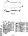
- figure 4 1 shows a casting 5 with two microchannels, which was produced using fibers 2 using the method described above.
- the cast part 5 is shown on the left in a perspective view and on the right in a lateral sectional view, so that the microchannels 6 are visible.
- the cast part 5 is designed as a coil whose turns are formed from cast aluminum wire with a flattened, rectangular cross-sectional profile. Such flat coils are suitable for making particularly good use of the available installation space. During operation, such coils can also become particularly hot, so that cooling is necessary can be. Prior art cooling devices would run counter to this goal.
- micro-channels for internal cooling of the individual windings can be introduced using the technology described here. Due to the microchannels shown, no additional components have to be provided.
- the channels can extend along winding sections. In the example shown, two channels 6 extend parallel to one another between two opposite sides of the coil along two winding sections.
- cooling media that have a low boiling point and flow through the microchannels in gaseous form.
- Liquid media suffer from a significant pressure loss in channels with a small cross section and therefore require correspondingly higher pressures, pump performance and, as a result, higher energy consumption when used in microchannels. As a result, the overall system is reduced in terms of efficiency and economy.
- the liquid cooling medium is selected according to the application-relevant operating temperatures.
- the cooling medium is present with a low admission pressure at the entrance of the micro-channels. When the component or the cooling jacket heats up, the cooling medium changes its aggregate state from liquid to gaseous.
- Refrigerants currently in use e.g.
- R123a ammonia
- R123a ammonia
- refrigerants can be selected for high efficiency, easy detectability, prevention of ozone damage, etc.
- the transition to the gaseous phase results in a high enthalpy absorption and thus a high cooling capacity.
- the transition to the gaseous state causes an increase in volume, which results in an increase in pressure in the system.
- the gaseous cooling medium is thus driven through the cooling channel without an increase in the admission pressure.
- other cast components can also be provided with the microchannels shown in the manner described and then cooled in the manner described when they are used.
- These other cast components can be, for example, a housing for a battery or an electric motor, or else a component of a machine tool, particularly for high-speed applications. It can also be a component of power electronics, a gas turbine, a compressor, a turbine blade, a heat exchanger or a burner.
- figure 5 shows the use of a frame 3 with clamped fibers 2 to produce the castings 5 with microchannels 6.
- the fibers 2 are clamped in a frame 3 outside the tool (on the left in the figure).
- the frame 3 is placed in the tool 1 (on the right in the figure) and the fibers 2 are cast around.
- FIG 5 shows how the frame 3 is positioned on a lower mold half 1.1, so that the frame itself lies outside the cavity 1.3 of the casting mold, but the fibers 2 clamped therein run through the cavity 1.3.
- the casting tool can then be closed by means of an upper tool half.
- the fibers are flushed with melt, which is fed into cavity 1.3.
- the frame and sections of the fibers 2 lie outside the cast part.
- the frame can then be removed and the fibers pulled out. Pulling can again take place in the machine-supported controlled process.
- the fibers can be designed not only as glass fibers but also as carbon fibers, aramid fibers, mineral fibers or metallic fibers.
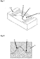
- figure 6 shows the casting 5 with multiple microchannels, its production in connection with figure 5 was described.
- the frame was removed and the glass fibers 2 were pulled out of the casting, so that where the fibers 2 ran, the microchannels 6 are formed.
- figure 7 shows a lower half of the tool 1.1 for producing a cast part 5 with a microchannel, with core marks 4 inside the tool serving as fixing or deflection points for the fiber 2 or fibers inside the cavity 1.3 of the tool. The fibers are clamped outside the cavity in the tool.
- the in figure 5 frames shown are used.
- the fiber 2 or a semi-finished textile product can map the complex path shown because it is stretched around the core marks 4 in the tool.
- the fiber is deflected three times.
- a bending radius of the fiber 2 guided around the core marks is at least ten times the diameter of the fiber and at least 0.5 mm.
- the core marks 4 are designed in such a way that they do not come into contact with the introduced aluminum melt and can be removed from the component after casting, or the core marks 4 can be connected to the tool so that they can be removed from the cast part when the cast part is removed to be pulled.
- wires in the cavity for fixing and/or deflecting the fiber for example exactly at the locations of the core marks 4 shown.
- the wires can be made of aluminum or of a material that is suitable for use with molten aluminum in solution to go.
- the fibers 2 are prepared using the preferably thin wires inside the tool or using an additional optional clamping frame outside the tool.
- the wires are cast in during the casting process so that they form a strong connection with the aluminum that is impervious to media.
- the wires remain in the casting while the fibers can be pulled out after the casting process.
- figure 8 shows the casting 5, with the in the figure 7 Casting tool shown was made with core brands 4.
- voids remain within the cast component 5 at the locations where the core marks were 4.
- the holes are then closed, for example by filling in more melt. This typically occurs before the fiber 2 is pulled out, with the pulling out being advantageously regulated again, since the risk of tearing off can be increased with fibers 2 bent in this way.
Landscapes
- Engineering & Computer Science (AREA)
- Mechanical Engineering (AREA)
- Casting Or Compression Moulding Of Plastics Or The Like (AREA)
- Manufacture Of Alloys Or Alloy Compounds (AREA)
Description
- Die Erfindung betrifft ein Verfahren zur Herstellung von Gussteilen mit Mikrokanälen. In verschiedensten technischen Prozessen, Anwendungen und Bauteilen ist es notwendig, überschüssige Wärme abzuführen und Bauteile vor einer Überhitzung zu schützen oder gezielt zu temperieren. Bei vielen Anwendungen wie beispielsweise Spulen in elektrischen Maschinen oder Kühlelementen in Batterien ist neben dem zu gewährleistenden Wärmeaustausch- und Abtransport der zur Verfügung stehenden Bauraum für die Bauteiltemperierung sowie der Bedarf möglichst dicht an die zu temperierenden Komponenten heran zu kommen von entscheidender Bedeutung. Bei Spulen in E-Maschinen wird die Kühlung heutzutage beispielsweise über eine gerichtete Zwangsbelüftung mittels Anströmen mit Luft erreicht. Nachteilig dabei ist, dass der Motor mit Luft durchströmt werden muss, wodurch Verschmutzungen in den Motor eingetragen werden können, welche zum Ausfall führen, beziehungsweise Wartungsmaßnahmen erfordern oder zusätzliche Versorgungsmöglichkeiten und Komponenten des Motors notwendig machen. Weiterhin ist die Wärmeleitfähigkeit und Wärmekapazität von Luft geringer als die anderer Kühlmedien, weshalb diese als wenig effizient einzustufen ist. Die gleichen Problemstellungen ergeben sich bei der Anwendung für Kühl-/Temperierelemente für Batterien und weitere elektronische Komponenten. Insbesondere der zur Verfügung stehende Bauraum erschwert die Umsetzung von konventionellen Kühl-/Temperierkonzepten mit Temperiermedien. Kühlkanäle können durch das Zusammensetzen eines Gehäuses aus mehreren Teilen gebildet werden. In einer Gehäusehälfte wird dabei die offen liegende Struktur der Kühlkanäle abgebildet, die andere Gehäusehälfte verschließt die Kühlkanäle, beziehungsweise Abwandlungen dieser beschriebenen Bauweise. In Gussbauteilen können Kühlkanäle mittels Kernen, eingegossenen Rohren oder in einem nachträglichen Bearbeitungsschritt erzeugt werden. Alle Varianten unterliegen geometrischen Beschränkungen, sodass Kühlkanäle einer Beschränkung im Verhältnis von Länge zu Durchmesser und der Komplexität der Form unterliegen.
- Nach dem Stand der Technik können weiterhin verlorene Kerne eingesetzt werden, um gießtechnisch komplexe Hohlstrukturen zu erzeugen. Dabei unterliegen die Kerne aufgrund der geringen Festigkeit geometrischen Beschränkungen. So kann kein beliebiges Verhältnis zwischen Länge, Durchmesser und Komplexität des Hohlraumes innerhalb des Gussbauteils eingestellt werden.
- Bekannt sind außerdem nachträglich in ein Gussbauteil eingebrachte Hohlstrukturen. Diese unterliegen starken geometrischen Beschränkungen in Bezug auf das Verhältnis von Länge zu Breite und Komplexität. Ebenfalls können ungewollte Verformungen innerhalb des Bauteils durch den Abbau von Eigenspannung bei der Einbringung der Hohlstrukturen entstehen.
- Batterie-Systeme für elektrisch angetriebene Fahrzeuge benötigen ein regelbares Kühlsystem, wobei das zusätzlich durch das Kühlsystem eingebrachte Gewicht zu Lasten der Reichweite des Fahrzeuges geht und minimiert werden soll.
- Gemäß
DE 11 2014 001 340 werden Kühlsammelleitungen zwischen einzelnen Lamellen eines Statorkerns gebildet. -
DE 11 2012 003 041 beschreibt die Herstellung von Mikrokanälen mittels Diffusionsschweißen und/oder Hartlöten, wodurch eine vollständige Kanaltrennung und die Beständigkeit gegen den herrschenden Betriebsdruck erreicht wird. -
DE 10 2014 102 954 A1 beschreibt ein Mikrokanal-Kühlrippe gebildet aus einer Metallplattenbaugruppe zur Kühlung von Batteriemodulen für elektrisch angetriebene Fahrzeuge. - Gemäß
DE 10 2005 033 150 A1 erfolgt die Kühlung elektrischer Bauelemente mittels Grundplatte und metallischer Folien, welche stoffschlüssig miteinander verbunden werden, sodass Kanäle mit einer Breite von 100 bis 350 um und einer Tiefe von 30 bis 150 µm entstehen. Der Mittlere Abstand zwischen den Kanälen beträgt 30 bis 300 µm. - In der
DE 10 2011056 905 A1 werden Mikrokanäle in metallische Oberflächen aufgebracht und durch Aufbauabscheidung verschlossen. -
DE 11 2006 0000 160 - Die Druckschrift
US 2003/173720 A1 offenbart Artikel mit Kanälen sehr kleinen Durchmessers, die sehr eng beieinander liegen. Diese können hergestellt werden, indem man längliche Kerne in eine Spannvorrichtung packt, sie einspannt und dann Matrixmaterial um die Kerne herum einführt. Das Matrixmaterial wird zu einem einheitlichen Körper geformt und verfestigt. Die Kerne werden herausgezogen, wobei an den Stellen, an denen sie sich befanden, offene Kanäle verbleiben. - Die
US 5 070 606 A zeigt ein Verfahren zur Herstellung eines Gegenstandes mit einem Körper mit einem oder mehreren geschlossenen Kanälen, die sich durch diesen hindurch erstrecken, wie z.B. für die Zirkulation von Flüssigkeiten. Der Körper wird vorzugsweise durch Metallabscheidung um eine oder mehrere Fasern herum gebildet, um die eingeschlossenen Kanäle zu erzeugen, wobei sich mindestens ein Ende der Fasern über den Körper hinaus erstreckt. Die Fasern werden dann aus den Kanälen im Körper herausgezogen, um die Kanäle, durch die Flüssigkeit zirkulieren kann, offen zu lassen. - In der Veröffentlichung "Effect of Working Fluid on Thermal Performance of Closed Loop Pulsating Heat Pipe: A Review", von SG Khedkar, P.R. Pachghare, Ashish M. Mahalle, veröffentlicht im International Journal of Emerging Technology and Advanced Engineering, Bd. 2, Nr. 3, März 2012 (ISSN: 2250-2459), werden pulsierende Wärmerohre diskutiert. Dies sind zweiphasige Wärmeübertragungsvorrichtungen, die auf der oszillierenden Strömung von Flüssigkeitsschwall und Dampfpfropfen in einem langen, in viele Windungen gebogenen Miniaturrohr beruhen. Das besondere Merkmal von pulsierenden Wärmerohren im Vergleich zu herkömmlichen Wärmerohren besteht darin, dass es keine Dochtstruktur gibt, die das Kondensat in den Heizabschnitt zurückführt, so dass es keinen Gegenstrom zwischen Flüssigkeit und Dampf gibt.
- Aufgabe der vorliegenden Erfindung ist es, eine möglichst effiziente Kühlung von Bauteilen zu ermöglichen, wobei Bauteilgröße und -gewicht möglichst gering gehalten werden sollen. Weiterhin sollen die genannten Nachteile von Kühlsystemen gemäß Stand der Technik vermieden werden.
- Die Aufgabe wird durch einen Herstellungsverfahren für ein Gussteil mit den Merkmalen des unabhängigen Anspruchs 1 gelöst.
- Vorteilhafte Ausgestaltungen der Erfindung ergeben sich aus den abhängigen Unteransprüchen sowie aus der Beschreibung und den Figuren.
- Bei der vorliegenden Erfindung kann es insbesondere vorgesehen sein, eine Kühlung direkt in Bauteile mittels Mikrokanäle zu integrieren oder ein Kühlelement bzw. Wärmetauscher kleiner zu dimensionieren, als es nach dem Stand der Technik möglich ist. Dabei ist insbesondere die Herstellung der Mikrokanäle und deren geometrische Gestaltung und Positionierung Teil der Erfindung. Mit der Erfindung soll es möglich werden, komplexe Kanäle in Gussbauteilen zu erzeugen, wobei diese ein großes Verhältnis zwischen Länge und Durchmesser aufweisen.
- Ein Herstellungsverfahren ist gemäß dieser Anmeldung also auf die Herstellung des Bauteils als Gussteil mit mindestens einem Mikrokanal gerichtet. Dabei wird mindestens eine Faser in einer Kavität eines Gießwerkzeugs fixiert. Die Faser erstreckt sich in der Kavität und ist dabei von einer Umwandung der Kavität beabstandet, wobei mindestens ein Ende der mindestens einen Faser außerhalb der Kavität liegt. Ein Gussmaterial wird in die Kavität eingeleitet und die mindestens eine Faser von dem Gussmaterial umgossen. Ein aus dem Gussmaterial gebildetes Gussteil wird aus der Kavität entnommen, wobei das aus der Kavität herausragende Ende der mindestens einen Faser aus dem Gussteil hervorsteht. Die mindestens eine Faser wird an dem aus dem Gussteil herausragenden Ende aus dem Gussteil herausgezogen sodass dort, wo die Faser in dem Gussteil verlaufen ist, ein den Mikrokanal bildender Hohlraum verbleibt.
- Durch die Verwendung einer Faser zur Herstellung des Mikrokanals wird es ermöglicht, den Mikrokanal mit einem komplexen Verlauf auszugestalten, also beispielsweise eine oder auch mehrere Biegungen in dem Mikrokanal zu erzeugen. Durch die Flexibilität der Faser kann diese auch dann gezogen werden, wenn sie eine oder mehrere Krümmungen oder Biegungen enthält. Ferner kann ein Durchmesser des Kanals besonders gering gehalten werden. Im Bauteil zur Verfügung stehender Platz kann so optimal ausgenutzt werden. Die mindestens eine Faser kann beispielsweise einen Durchmesser haben, der etwa 5 µm beträgt. Der Durchmesser kann auch mehr als 5 µm betragen und beispielsweise höchstens einige hundert µm, etwa höchstens 500 µm betragen.
- Die mindestens eine Faser ist typischerweise mindestens 1 mm lang. Es kann sein, dass die Länge der mindestens einen Faser höchstens einige hundert mm beträgt, etwa höchstens 500 mm, um die Faser noch gut entfernen zu können.
- Ebenfalls mit Blick auf das Entfernen der Faser kann es vorgesehen sein, dass ein Biegeradius der mindestens einen Faser, wenn sie in der Kavität angeordnet ist, mindestens ein Zehnfaches des Durchmessers der Faser beträgt. Alternativ oder zusätzlich kann als kleinster Biegeradius 0,5 mm vorgesehen sein. Durch solche Biegeradien kann das Abreißen der mindestens einen Faser verhindert werden.
- Dieser kleinste Biegeradius spiegelt sich dann in dem herzustellenden Gussteil als kleinster Biegeradius des darin befindlichen mindestens einen Mikrokanals wieder.
- Ein Schmelzpunkt der mindestens einen Faser liegt typischerweise bei mindestens 1000°C, beispielsweise bei ca. 1200°C. Alternativ oder zusätzlich wird die Faser typischerweise so gewählt, dass ihre Temperaturbeständigkeit mindestens 750°C beträgt.
- Bei dem Verfahren kann die mindestens eine Faser zum Beispiel in einem Rahmen eingespannt werden. Der Rahmen kann in dem Gießwerkzeug positioniert werden. Der Rahmen kann dann etwa die Kavität begrenzen, so dass das Gussmaterial in ein Inneres des Rahmens eingeleitet wird.
- Bei dem Herstellungsverfahren wird als Gussmaterial vorzugsweise Aluminiumschmelze, etwa Anticorodal AC 70, verwendet.
- Es kann aber auch sein, dass ein anderes Gussmaterial verwendet wird, das beispielsweise Aluminium und/oder Magnesium und/oder Zink und/oder Blei und/oder Kupfer enthält. Es kommen also etwa Legierungen der genannten Materialien in Frage. Dabei werden beispielsweise Gussmaterialien verwendet mit Schmelzpunkt unter 700° C, vorzugsweise unter 600° C.
- Als Gießverfahren können beispielsweise ein Niederdruck- oder Schwerkraftgießverfahren zum Einsatz kommen. Hiermit kann vorteilhaft erreicht werden, dass die Fasern beim Einfüllen des Gussmaterials an der vorgesehenen Position verbleiben und außerdem keine stoffschlüssige Verbindung mit dem Gussmaterial eingehen.
- Es können aber auch Druckguss-, Feinguss- oder Lost Foam-Verfahren verwendet werden.
- Für das Gießwerkzeug können sowohl Dauerformen als auch verlorene Formen verwendet werden.
- Die mindestens eine Faser kann zum Beispiel als Glasfaser, etwa aus S-Glas oder E-Glas, als Kohlenstofffaser, Aramidfaser, mineralische Faser oder metallische Faser ausgebildet sein. Diese Materialien haben sich als besonders geeignet herausgestellt, um die stoffschlüssige Verbindung mit dem Gussmaterial zu vermeiden.
- Die genannten optionalen Weiterentwicklungen können jeweils für sich genommen oder in Kombination dazu beitragen, dass die Fasern sich mit geringem Kraftaufwand aus dem Gussbauteil herausziehen lassen.
- Beim Entfernen der mindestens einen Faser aus dem Gussbauteil zur Erzeugung des mindestens einen Mikrokanals kann eine Zugkraft zum Herausziehen der mindestens einen Faser gesteuert oder geregelt werden. Die Kraft kann also insbesondere während des Herausziehens variiert werden, um ein Abreißen der mindestens einen Faser zu vermeiden. Das kann beispielsweise dann angezeigt sein, wenn die Faser einen gekrümmten oder abgewinkelten Verlauf aufweist.
- Es kann in möglichen Ausführungen auch vorgesehen sein, dass als Fasern dicke Einzelfasern zum Einsatz kommen. Es kann aber auch vorgesehen sein, dass die mindestens eine Faser eine Vielzahl Fasern umfasst, die als Garn, Hybridgarn, Faserbündel, Rovings oder Geflecht bereitgestellt werden. Dadurch kann beispielsweise einerseits einen Mikrokanal mit entsprechend größerem Durchmesser erzielt werden und andererseites das Herausziehen vereinfacht werden, da die genannten Elemente im Vergleich zu Einzelfasern kompressibel sein können.
- Dabei ist es auch möglich, dass die genannten mehrere Fasern umfassenden Garne, Hybridgarne, Faserbündel, Rovings oder Geflechte entfernt werden, indem die darin enthaltenen Fasern einzeln herausgezogen werden.
- Weiterhin können Hybridgarne mit Außenmantel aus Glasfasern und einem temperaturstabilen Kern aus Stahlfilamenten eingesetzt werden.
- Auf diese Weise können die Eigenschaften der Fasern an den Gießprozess und an die Anforderungen der zu schaffenden Mikrokanäle angepasst werden.
- Im Folgenden wird erläutert, wie, sofern vorgesehen, ein komplexer Verlauf für die Fasern hergestellt werden kann.
- In einer möglichen Ausführung kann in der Kavität mindestens eine Kernmarke bereitgestellt werden wobei zumindest eine der mindestens einen Faser mittels der mindestens einen Kernmarke umgelenkt wird.
- Dabei kann in dem Verfahren ein weiterer Schritt zum Entfernen der mindestens einen Kernmarke aus dem Gussteil vorgesehen sein. Die Kernmarke kann mit dem Gießwerkzeug verbunden sein, so dass die Kernmarke beim Entnehmen des Gussteils aus dem Werkzeug entfernt wird. Durch die mindestens eine Kernmarke verursachte Löcher in dem Gussteil können dann, beispielsweise vor dem Entfernen der mindestens einen Kernmarke, geschlossen werden, etwa durch Einbringen von Gussmaterial in die Löcher.
- Alternativ oder zusätzlich kann in der Kavität mindestens ein Draht zur Fixierung und/oder zum Umlenken der Faser bereitgestellt werden, wobei der mindestens eine Draht aus Aluminium gebildet ist oder aus einem Material, das geeignet ist, mit dem verwendeten Gussmaterial eine Stoffschlüssige Verbindung einzugehen oder in Lösung zu gehen. Der so ausgestaltete Draht verbindet sich dann mit dem in die Kavität eingeleiteten Gussmaterial auf feste und für Medien dichte weise und muss nicht entfernt werden. Wenn der Draht nicht vollständig mit dem Gussmaterial in Lösung geht, kann er in manchen Ausführungen als Fremdkörper im Gussteil verbleiben ohne dessen Leistungsfähigkeit wesentlich zu beeinträchtigen oder zu einer strukturellen Schwächung des Gussteils zu führen. Der mindestens eine Draht kann beispielsweise als dünner Draht ausgebildet sein. Er kann innerhalb des Werkzeuges oder in einem Spannrahmen außerhalb des Werkzeuges vorbereitet werden.
- Weiterhin ist es alternativ oder zusätzlich auch möglich, die mindestens eine Faser mit einem temperaturstabilen Matrix-Werkstoff, vorzugsweise Wasserglas oder Silikatklebstoff, zu infiltrieren. Die mindestens eine Faser wird typischerweise in einem vorgeschalteten Prozess in ein Formgebendes Werkzeug eingebracht und mit dem temperaturstabilen Matrix-Werkstoff infiltriert um vorkonfektionierte Preforms zu erzeugen, die eine maximal komplexe Gestalt annehmen können. Die auf diese Weise hergestellte Faser ist formstabil und kann einen gebogenen oder abgewinkelten Verlauf aufweisen. Sie kann dann in der Kavität bereitgestellt werden, wobei ein Vorteil darin liegt, dass für den gebogenen oder abgewinkelten Lauf keine Drähte oder Kernmarken oder zumindest weniger Drähte und Kernmarken benötigt werden als bei flexiblen Fasern. Beispielsweise kann die Faser dann nur mittels eines Rahmens oder nur mittels Drähten oder Kernmarken fixiert werden.
- Ein Grad der Infiltration ist so gewählt, dass einerseits ausreichende Formstabilität besteht und andererseits die Entfernung der infiltrierten Faser oder Fasern durch Herausziehen aus dem Gussteil möglich ist.
- Die Erfindung bezieht sich auch auf ein Bauteil, insbesondere Gussteil, mit dem die effiziente Kühlung ermöglicht werden kann.
- Das Gussteil weist mindestens einen Mikrokanal auf, der auf die oben beschriebene Weise hergestellt ist. Das Gussteil kann dabei beispielsweise als Spule ausgebildet sein oder als Gehäuse einer Batterie oder eines Elektromotors. Ebenso kann es sich um eine Komponente einer Werkzeugmaschine, beispielsweise für eine Hochgeschwindigkeitsanwendung, eine Komponente einer Leistungselektronik, einer Gasturbine, eines Verdichters, einer Turbinenschaufel, eines Wärmetauschers oder eines Brenners handeln.
- Außerdem bezieht sich die Erfindung auf die Verwendung des hier beschriebenen Gussteils. Die Ausgestaltung der auf die beschriebene Weise gefertigten Kanäle, insbesondere ihr geringer Durchmesser und typischerweise komplexe Form kann zur Folge haben, dass bestimmte Arten der Verwendung vorteilhaft sind.
- Beispielsweise können in Verfahren zur Verwendung des Gussteils Kühlmedien eingesetzt werden, die einen niedrigen Siedepunkt aufweisen und die Mikrokanäle zumindest während eines Teils der Verwendung gasförmig durchströmen. Flüssige Medien erleiden in Kanälen geringem Querschnitt einen erheblichen Druckverlust und benötigen daher bei Einsatz in Mikrokanälen entsprechend höhere Drücke, Pumpenleistungen und in Folge dessen einen höheren Energieaufwand. Dadurch wird das Gesamtsystem im Wirkungsgrad und der Wirtschaftlichkeit reduziert.
- Im Fall der hier gezeigten Mikrokanäle kann das Kühlmedium entsprechend der für die Anwendung relevanten Einsatztemperaturen ausgewählt werden.
- Das Kühlmedium steht typischerweise mit einem geringen Vordruck am Eintritt der Mikrokanäle an.
- Ein Kühlmedium kann beispielsweise in flüssigem Aggregatzustand in den mindestens einen Mikrokanal eingeleitet werden.
- Es kann vorgesehen sein, dass das Kühlmedium bei Erwärmung des Bauteils bzw. des Kühlmantels seinen Aggregatzustand von flüssig zu gasförmig ändert.
- Als mögliche Kühlmedien können aktuell eingesetzte Kältemittel verwendet werden. Beispielsweise können R123a oder Ammoniak verwendet werden.
- Der Siedepunkt der Kühlmittel kann durch den Vordruck gezielt beeinflusst werden kann. Entsprechend der Anwendung können Kältemittel für eine hohe Effizienz, leichte Detektierbarkeit, Vermeidung von Ozonschäden usw. ausgewählt werden. Durch den möglichen Übergang in die gasförmige Phase resultieren eine hohe Enthalpie-Aufnahme und damit eine hohe Kühlleistung. Gleichzeitig entsteht durch den Übergang in den gasförmigen Zustand ein Volumenanstieg, woraus ein Druckanstieg im System resultiert. Das gasförmige Kühlmedium wird so ohne einen Anstieg des Vordruckes durch den Kühlkanal getrieben.
- Der Kühlprozess kann beispielsweise auch nach dem Thermosiphon- oder Heatpipe-Prinzip oder nach dem Prinzip einer Kältemaschine erfolgen.
- Beispielhafte Ausführungen der Erfindung werden anhand der angehängten Figuren erläutert.
- Darin zeigen
- Figur 1
- schematisch ein Gießwerkzeug, mit einer Kavität, in der eine Faser angeordnet wird,
- Figur 2
- ein Gussteil mit einem Mikrokanal, hergestellt mit dem Gießwerkzeug aus
Figur 1 , - Figur 3
- eine Seitenansicht und einen Schnitt des Gussteils aus
Figur 2 , - Figur 4
- eine Schrägansicht und einen Schnitt eines als Spule ausgebildeten Gussteils mit einem Mikrokanal,
- Figur 5
- ein Gießwerkzeug, in dem ein Rahmen mit eingespannten Fasern positioniert wird,
- Figur 6
- ein mit dem Gießwerkzeug aus
Figur 5 hergestelltes Gussteil, - Figur 7
- ein Gießwerkzeug mit einer Kavität und darin angeordneten Kernmarken zum Umlenken einer in der Kavität verlaufenden Faser, und
- Figur 8
- einen Schnitt durch ein mit dem Gießwerkzeug aus
Figur 7 hergestelltes Gussteil, mit einem Mikrokanal und durch die Kernmarken verursachten Löchern. -
Figur 1 zeigt oben eine schematische Darstellung einer Faser 2, welche vor einem Gießprozess in einem in der Figur unten dargestellten Gießwerkzeug 1 positioniert wird. In derFigur 1 ist durch einen Pfeil angedeutet, wie die aus Fasermaterial gebildete Faser 2 in eine Kavität 1.3 des Werkzeugs eingebracht wird, wobei eine Biegung der Faser 2 einem Verlauf der Kavität 1.3 folgt. So kann die Faser 2 im Wesentlichen zentral in der Kavität 1.3 angeordnet werden, so dass sie sich von einer Umwandung der Kavität 1.3 beabstandet erstreckt. - Die Faser 2 wird in der Kavität des Gießwerkzeugs so fixiert, dass ihre Enden aus der Kavität herausragen.
- Anschließend wird Aluminiumschmelze, beispielsweise Anticorodal AC 70, als Gussmaterial in die Kavität 1.3 eingeleitet, so dass die Faser 2, d.h. ein Bereich der Faser, der in der Kavität 1.3 liegt, von dem Gussmaterial umgossen wird.
- In anderen Ausführungen kann das Gussmaterial anstatt oder neben Aluminium auch Magnesium und/oder Zink und/oder Blei und/oder Kupfer enthalten.
- Die Faser 2 ist als Glasfaser, beispielsweise aus S-Glas oder E-Glas ausgebildet. In anderen Ausführungen kann sie auch als Kohlenstofffaser, Aramidfaser, mineralische Faser oder metallische Faser gewählt werden.
- Im gezeigten Beispiel ist die Faser 2 in einem vorgeschalteten Prozess in ein Formgebendes Werkzeug eingebracht und mit einem temperaturstabilen Matrix-Werkstoff (beispielsweise Wasserglas, Silikatklebstoff usw.) infiltriert worden. So entstehende vorkonfektionierte Preforms können eine maximale komplexe Gestalt annehmen und werden anschließend in das Gießwerkzeug eingelegt. Durch den gewählten Grad der Infiltration werden Formstabilität der Preforms und Entformbarkeit aus dem Gußteil erreicht.
- Die Faser 2 hat einen Durchmesser von zwischen 5 µm und500 µm eine Länge von mindestens 1 mm und höchstens 500 mm.
- Ein Biegeradius der Faser 2 beträgt mindestens ein Zehnfaches des Durchmessers der Faser und mindestens 0,5 mm.
- Ein Schmelzpunkt der Faser liegt bei über 1200°C und eine Temperaturbeständigkeit bei über 750°C.
- Zwischen Faser 2 und Aluminiumschmelze besteht ein nicht-benetzendes System. Dadurch werden in verschiedenen Gießverfahren eingegossene Fasern, Gewebe, Gelege und andere Faserhalbzeuge nicht benetzt und gehen keine stoffschlüssige Verbindung mit dem Aluminium ein. So können Fasern gezielt in den Gießprozess eingebracht, umgossen und anschließend wieder aus dem Bauteil herausgezogen werden. In einem nachgeschalteten Prozessschritt werden die Fasern aus dem Gussbauteil gezogen, wodurch ein Mikrokanal entsteht (siehe auch
Figuren 2 und3 ). - Versuche haben beispielsweise gezeigt, dass Glasfasern (S-Glas, E-Glas) und Aluminium (Anticorodal AC 70) im Niederdruck- und Schwerkraftgießprozess keine Verbindung miteinander eingehen. So können die Fasern mit einer Zugprüfmaschine anschließend mit geringem Kraftaufwand aus dem Gussbauteil herausgezogen werden.
- Es ist aber auch möglich, Druckguss-, Feinguss- oder Lost Foam-Verfahren zu verwenden.
- Zum Entfernen der Faser aus dem Gussbauteil zur Erzeugung eines Mikrokanals wird das Gussteil aus der Kavität entnommen und die Faser in einem maschinengestützten und geregelten Prozess aus dem Gussbauteil herausgezogen, um ein Abreißen innerhalb des Bauteils zu verhindern.
- Die Verwendung von Faserbündeln oder Rovings oder Garnen oder Fasergarnen oder Geflechten ist ebenfalls möglich. Weiterhin können Hybridgarnen mit Außenmantel aus Glasfasern und einem temperaturstabilen Kern aus Stahlfilamenten eingesetzt werden.
-
Figur 2 zeigt eine schematische Darstellung des dünnwandig ausgebildeten Gussteils 5 mit Mikrokanal 6, dessen Herstellung im Zusammenhang mitFigur 1 beschrieben wurde. Es weist den gebogenen bzw. geschwungenen Verlauf der in derFigur 1 gezeigten Kavität 1.3 auf. - Das aus dem Gussmaterial gebildete Gussteil 5 wurde aus der Kavität 1.3 entnommen, wobei an entgegengesetzten Enden des Gussteil 5 die Faser 2 hervorsteht.
- Eines der Enden der Faser 2 wird gegriffen und aus dem Gussteil 5 herausgezogen, wobei der oben beschriebene maschinengestütze und geregelte Prozess verwendet wird.
-
Figur 3 zeigt eine schematische Darstellung des dünnwandigen Gussteils 5 mit Mikrokanal 6 ausFigur 2 in einer Seitenansicht (oben) und in einer Schnittdarstellung (unten). - In der Schnittdarstellung ist der zentral in dem Gussteil 5 verlaufende Mikrokanal 6 zu erkennen, der einen identischen und über die Länge gleichbleibenden Abstand zu parallel verlaufenden geschwungenen Außenseiten des Gussteils 5 aufweist und sich über eine komplette Länge des Gussteils 5 erstreckt und an entgegengesetzten Enden aus dem Gussteil 5 hervortritt. Diese Ausgestaltung des Mikrokanals 6 wird durch die in im Zusammenhang mit
Figuren 1 und 2 beschriebene Herstellungsmethode ermöglicht. -
Figur 4 zeigt ein Gussteil 5 mit zwei Mikrokanälen, welches mit der oben beschriebenen Methode, unter Einsatz von Fasern 2 hergestellt wurde. Links ist das Gussteil 5 in einer perspektivischen Ansicht und rechts in einer seitlichen Schnittansicht gezeigt, sodass die Mikrokanäle 6 sichtbar sind. - Das Gussteil 5 ist als Spule ausgebildet, deren Windungen aus gegossenem Aluminiumdraht mit abgeflachtem rechteckigem Querschnittsprofil geformt werden. Derartige flach ausgestaltete Spulen sind geeignet, zur Verfügung stehenden Bauraum besonders gut auszunutzen. Im Betrieb können solche Spulen dadurch auch besonders heiß werden, sodass eine Kühlung notwendig sein kann. Kühlvorrichtungen gemäß Stand der Technik würden diesem Ziel entgegenlaufen. In solchen gegossenen Spulen für elektrische Maschinen können mit der hier beschriebenen Technik Mikrokanäle zur innenliegenden Kühlung der einzelnen Windungen eingebracht werden. Durch die gezeigten Mikrokanäle müssen keine zusätzlichen Komponenten bereitgestellt werden. Die Kanäle können sich entlang von Windungsabschnitten erstrecken. Im gezeigten Beispiel erstrecken sich zwei Kanäle 6 parallel zueinander zwischen zwei gegenüberliegenden Seiten der Spule entlang zweier Windungsabschnitte.
- Beim Betrieb von Bauteilen mit mindestens einem Mikrokanal, insbesondere beispielsweise beim Betrieb der gezeigten Spule, können diese auf die im Folgenden beschriebene Weise vorteilhaft gekühlt werden.
- Vorteilhaft ist der Einsatz von Kühlmedien, die einen niedrigen Siedepunkt aufweisen und die Mikrokanäle gasförmig durchströmen. Flüssige Medien erleiden in Kanälen geringem Querschnitt einen erheblichen Druckverlust und benötigen daher bei Einsatz in Mikrokanälen entsprechend höhere Drücke, Pumpenleistungen und in Folge dessen einen höheren Energieaufwand. Dadurch wird das Gesamtsystem im Wirkungsgrad und der Wirtschaftlichkeit reduziert. In Kombination mit Mikrokanälen wird das flüssige Kühlmedium entsprechend der Anwendung relevanten Einsatztemperaturen ausgewählt. Das Kühlmedium steht mit einem geringen Vordruck am Eintritt der Mikrokanäle an. Bei Erwärmung des Bauteils bzw. des Kühlmantels ändert das Kühlmedium seinen Aggregatzustand von flüssig zu gasförmig. Als mögliche Kühlmedien können aktuell eingesetzte Kältemittel (z.B. R123a, Ammoniak) verwendet werden, deren Siedepunkt durch den Vordruck gezielt beeinflusst werden kann. Entsprechend der Anwendung können Kältemittel für eine hohe Effizienz, leichte Detektierbarkeit, Vermeidung von Ozonschäden usw. ausgewählt werden. Durch den Übergang in die gasförmige Phase resultieren eine hohe Enthalpie-Aufnahme und damit eine hohe Kühlleistung. Gleichzeitig entsteht durch den Übergang in den gasförmigen Zustand ein Volumenanstieg, woraus ein Druckanstieg im System resultiert. Das gasförmige Kühlmedium wird so ohne einen Anstieg des Vordruckes durch den Kühlkanal getrieben.
- Außer Spulen können auf die beschriebene Weise auch andere gegossene Bauteile mit den gezeigten Mikrokanälen versehen und dann bei ihrer Verwendung auf die beschriebene Weise gekühlt werden. Bei diesen anderen gegossenen Bauteilen kann es sich beispielsweise um ein Gehäuse einer Batterie oder eines Elektromotors handeln oder auch um eine Komponente einer Werkzeugmaschine, insbesondere für Hochgeschwindigkeitsanwendungen. Es kann sich auch um eine Komponente einer Leistungselektronik, einer Gasturbine, eines Verdichters, einer Turbinenschaufel, eines Wärmetauschers oder eines Brenners handeln.
-
Figur 5 zeigt die Verwendung eines Rahmens 3 mit eingespannten Fasern 2 zur Herstellung der Gussteile 5 mit Mikrokanälen 6. - Die Fasern 2 werden in einem Rahmen 3 außerhalb des Werkzeuges verspannt (links in der Figur). Im Gießprozess wird der Rahmen 3 in das Werkzeug 1 eingelegt (rechts in der Figur) und die Fasern 2 werden umgossen.
- In der
Figur 5 ist gezeigt, wie der Rahmen 3 auf einer unteren Werkzeughälfte 1.1 positioniert wird, so dass sich der Rahmen selbst außerhalb der Kavität 1.3 des Gießwerkzeugs liegt, die darin eingespannten Fasern 2 aber durch die Kavität 1.3 verlaufen. Das Gießwerkzeug kann dann mittels einer oberen Werkzeughälfte verschlossen werden. Im Gießprozess, der als Niederdruck- oder Schwerkraftgießverfahren ausgeführt wird, wird werden die Fasern mit Schmelze, die in die Kavität 1.3 geleitet wird, umspült. - Nach Entnehmen des aus der Schmelze gebildeten Gussteils 5 liegen der Rahmen und Abschnitte der Fasern 2 außerhalb des Gussteils. Der Rahmen kann dann entfernt und die Fasern herausgezogen werden. Das ziehen kann wieder in dem maschinengestützten geregelten Prozess erfolgen.
- Auch hier können die Fasern nicht nur als Glasfasern sondern auch als Kohlenstofffasern, Aramidfasern, mineralische Fasern oder metallische Fasern ausgebildet sein.
-
Figur 6 zeigt das Gussteil 5 mit mehreren Mikrokanälen, dessen Herstellung im Zusammenhang mitFigur 5 beschrieben wurde. In einem dem Gießen nachgeschalteten Prozessschritt wurde der Rahmen entfernt und die Glasfasern 2 wurden aus dem Gußteil gezogen, sodass dort, wo die Fasern 2 verlaufen sind, die Mikrokanäle 6 entstehen. -
Figur 7 zeigt eine untere Werkzeughälfte 1.1 zur Herstellung eines Gussteils 5 mi einem Mikrokanal, wobei Kernmarken 4 innerhalb des Werkzeuges als Fixierungs- oder Umlenkungspunkte für die Faser 2 bzw. Fasern innerhalb der Kavität 1.3 des Werkzeuges dienen. Die Fasern werden außerhalb der Kavität im Werkzeug verspannt. Dafür kann optional auch der inFigur 5 gezeigte Rahmen verwendet werden. - Die Faser 2 bzw. ein textiles Halbzeug kann dadurch, dass es um die Kernmarken 4 im Werkzeug gespannt ist den gezeigten komplexen Pfad abbilden. In der
Figur 7 wird die Faser drei Mal umgelenkt. Ein Biegeradius der um die Kernmarken gelenkten Faser 2 beträgt mindestens ein Zehnfaches des Durchmessers der Faser und mindestens 0,5 mm. - Die Kernmarken 4 sind so ausgebildet, dass die mit der eingeleiteten Aluminiumschmelze nicht in Verbindung gehen und sich nach dem Gießen aus dem Bauteil entfernen lassen, bzw. können die Kernmarken 4 mit dem Werkzeug verbunden sein, so dass sie beim Entnehmen des Gussteils aus dem Gussteil gezogen werden.
- Alternativ ist es auch möglich, in der Kavität Drähte zur Fixierung und/oder zum Umlenken der Faser bereitzustellen, beispielsweise genau an den Orten der gezeigten Kernmarken 4. Die Drähte können aus Aluminium gebildet sein oder aus einem Material, das geeignet ist, mit Aluminiumschmelze in Lösung zu gehen.
- Die Fasern 2 werden mittels der, vorzugsweise dünnen, Drähte innerhalb des Werkzeuges oder mittels einem zusätzlichen optionalen Spannrahmen außerhalb des Werkzeuges vorbereitet. Im Gießprozess werden die Drähte mit eingegossen, sodass sie eine feste und für Medien dichte Verbindung mit dem Aluminium eingehen. Die Drähte verbleiben im Gußteil, während die Fasern nach dem Gießprozess herausgezogen werden können.
-
Figur 8 zeigt das Gussteil 5, das mit dem in derFigur 7 gezeigten Gießwerkzeug mit Kernmarken 4 hergestellt wurde. - Nach dem Gießprozess verbleiben Leerstellen innerhalb des Gussbauteils 5 an den Orten, an denen sich die Kernmarken befunden haben 4. Die Löcher werden anschließend verschlossen, beispielsweise durch Einfüllen von weiterer Schmelze. Dies geschieht typischerweise vor dem Herausziehen der Faser 2, wobei das Herausziehen vorteilhaft wieder geregelt wird, da die Gefahr des Abreißens bei derartig gebogenen Fasern 2 verstärkt gegeben sein kann.
-
- 1
- Gießwerkzeug
- 1.1
- Untere Werkzeughälfte
- 1.3
- Kavität
- 2
- Faser
- 3
- Rahmen
- 4
- Kernmarke
- 5
- Gussteil
- 6
- Mikrokanal
- 7
- Loch
Claims (11)
- Herstellungsverfahren für ein Gussteil (5) mit mindestens einem Mikrokanal (6), wobei- mindestens eine Faser (2) in einer Kavität (1.3) eines Gießwerkzeugs (1) fixiert wird, so dass die mindestens eine Faser (2) sich in der Kavität (1.3) von einer Umwandung der Kavität (1.3) beabstandet erstreckt und mindestens ein Ende der mindestens einen Faser (2) außerhalb der Kavität (1.3) liegt,- ein Gussmaterial in die Kavität (1.3) eingeleitet und die mindestens eine Faser (2) von dem Gussmaterial umgossen wird,- ein aus dem Gussmaterial gebildetes Gussteil (5) aus der Kavität (1.3) entnommen wird, wobei aus dem Gussteil (5) das mindestens eine Ende der mindestens einen Faser (2) hervorsteht,- die mindestens eine Faser (2) aus dem Gussteil (5) herausgezogen wird,wobeiin der Kavität (1.3) mindestens eine Kernmarke (4) bereitgestellt wird und zumindest eine der Fasern (2) mittels der mindestens einen Kernmarke (4) umgelenkt wirdund/oderwobei in der Kavität (1.3) mindestens ein Draht zur Fixierung und/oder zum Umlenken der Faser (2) bereitgestellt wird, wobei der mindestens eine Draht aus Aluminium gebildet ist oder aus einem Material, das geeignet ist, sich mit dem Gussmaterial stoffschlüssig zu verbinden oder mit dem Gussmaterial in Lösung zu gehen und/oderwobei die mindestens eine Faser (2) mit einem temperaturstabilen Matrix-Werkstoff infiltriert wird, zum Herstellen einer Formstabilität für die Faser (2) mit gebogenem oder abgewinkeltem Verlauf.
- Herstellungsverfahren gemäß Anspruch 1, wobei die mindestens eine Faser (2) einen Durchmesser von mindestens 5 µm und/oder höchstens 1000 µm aufweist und/oder wobei die mindestens eine Faser (2) eine Länge von mindestens 1 mm und/oder höchstens 500 mm aufweist.
- Herstellungsverfahren gemäß einem der vorhergehenden Ansprüche, wobei ein Biegeradius der mindestens einen Faser (2) mindestens ein Zehnfaches des Durchmessers der Faser und/oder mindestens 0,5 mm beträgt.
- Herstellungsverfahren gemäß einem der vorhergehenden Ansprüche, wobei ein Schmelzpunkt der mindestens einen Faser (2) bei mindestens 1000°C liegt und/oder eine Temperaturbeständigkeit der mindestens einen Faser bei mindestens 750°C liegt
und/oder
wobei die mindestens eine Faser (2) als Glasfaser, Kohlenstofffaser, Aramidfaser, mineralische Faser oder metallische Faser gewählt wird. - Herstellungsverfahren gemäß einem der vorhergehenden Ansprüche wobei das Gussmaterial Aluminiumschmelze ist, vorzugsweise Anticorodal AC 70, oder das Gussmaterial Aluminium und/oder Magnesium und/oder Zink und/oder Blei und/oder Kupfer enthält und/oder wobei als Gießverfahren ein Niederdruck- oder Schwerkraftgießverfahren verwendet wird oder wobei ein Druckguss-, Feinguss- oder Lost Foam-Verfahren verwendet wird.
- Herstellungsverfahren gemäß einem der vorhergehenden Ansprüche, wobei die mindestens eine Faser (2) eine Vielzahl Fasern umfasst, die als Garn, Hybridgarn, Roving, Faserbündel oder Geflecht ausgestaltet sind.
- Herstellungsverfahren gemäß einem der vorhergehenden Ansprüche, wobei in der Kavität (1.3) die mindestens eine Kernmarke (4) bereitgestellt wird und die zumindest eine der Fasern (2) mittels der mindestens einen Kernmarke (4) umgelenkt wird, wobei das Verfahren weiterhin einen Schritt zum Verschließen von durch die mindestens eine Kernmarke (4) verursachten Löchern (7) in dem Gussteil (5) umfasst.
- Herstellungsverfahren gemäß einem der vorhergehenden Ansprüche, wobei die mindestens eine Faser (2) mit Wasserglas oder Silikatklebstoff infiltriert wird, zum Herstellen der Formstabilität für die Faser (2) mit gebogenem oder abgewinkeltem Verlauf.
- Herstellungsverfahren gemäß einem der vorhergehenden Ansprüche, wobei die mindestens eine Faser (2) in einem Rahmen (3) eingespannt wird und der Rahmen (3) in dem Gießwerkzeug (1) positioniert wird.
- Herstellungsverfahren gemäß einem der vorhergehenden Ansprüche, wobei eine Zugkraft zum Herausziehen der mindestens einen Faser (2) gesteuert oder geregelt wird.
- Herstellungsverfahren gemäß einem der vorhergehenden Ansprüche, wobei das Gussteil (5) ausgebildet wird als Spule oder als Gehäuse einer Batterie oder eines Elektromotors, oder als Komponente einer Werkzeugmaschine, einer Leistungselektronik, einer Gasturbine, eines Verdichters, einer Turbinenschaufel, eines Wärmetauschers oder eines Brenners.
Applications Claiming Priority (2)
| Application Number | Priority Date | Filing Date | Title |
|---|---|---|---|
| DE102017125167 | 2017-10-26 | ||
| PCT/EP2018/079515 WO2019081774A1 (de) | 2017-10-26 | 2018-10-26 | Verfahren zur herstellung von gussteilen mit mikrokanälen |
Publications (2)
| Publication Number | Publication Date |
|---|---|
| EP3700697A1 EP3700697A1 (de) | 2020-09-02 |
| EP3700697B1 true EP3700697B1 (de) | 2022-08-24 |
Family
ID=64316480
Family Applications (1)
| Application Number | Title | Priority Date | Filing Date |
|---|---|---|---|
| EP18803559.6A Not-in-force EP3700697B1 (de) | 2017-10-26 | 2018-10-26 | Verfahren zur herstellung von gussteilen mit mikrokanälen |
Country Status (2)
| Country | Link |
|---|---|
| EP (1) | EP3700697B1 (de) |
| WO (1) | WO2019081774A1 (de) |
Family Cites Families (8)
| Publication number | Priority date | Publication date | Assignee | Title |
|---|---|---|---|---|
| US5070606A (en) * | 1988-07-25 | 1991-12-10 | Minnesota Mining And Manufacturing Company | Method for producing a sheet member containing at least one enclosed channel |
| US6939505B2 (en) * | 2002-03-12 | 2005-09-06 | Massachusetts Institute Of Technology | Methods for forming articles having very small channels therethrough, and such articles, and methods of using such articles |
| JP4955943B2 (ja) | 2005-06-28 | 2012-06-20 | クラリオン株式会社 | 情報端末および計算機資源管理方法 |
| DE102005033150A1 (de) | 2005-07-13 | 2007-01-25 | Atotech Deutschland Gmbh | Mikrostrukturierter Kühler und dessen Verwendung |
| US8753071B2 (en) | 2010-12-22 | 2014-06-17 | General Electric Company | Cooling channel systems for high-temperature components covered by coatings, and related processes |
| GB2509255B (en) | 2011-07-19 | 2018-07-04 | Velocys Inc | A cylindrical microchannel device |
| US9196935B2 (en) | 2013-03-12 | 2015-11-24 | Gm Global Technology Operations, Llc | Micro-channel cooling fin design based on an equivalent temperature gradient |
| US9419479B2 (en) | 2013-03-14 | 2016-08-16 | Baldor Electric Company | Micro-channel heat exchanger for stator of electrical machine with supply header |
-
2018
- 2018-10-26 EP EP18803559.6A patent/EP3700697B1/de not_active Not-in-force
- 2018-10-26 WO PCT/EP2018/079515 patent/WO2019081774A1/de not_active Ceased
Also Published As
| Publication number | Publication date |
|---|---|
| EP3700697A1 (de) | 2020-09-02 |
| WO2019081774A1 (de) | 2019-05-02 |
Similar Documents
| Publication | Publication Date | Title |
|---|---|---|
| EP2933901B1 (de) | Stator einer elektrischen Maschine und dessen Herstellung | |
| EP2701286B1 (de) | Gehäuse für eine elektrische Maschine mit mäanderförmigem Kühlkanal und Leitgeometrien | |
| EP3576894B1 (de) | Verfahren zum herstellen einer kühlvorrichtung | |
| DE102016216019A1 (de) | Einsatz für einen Kühlmantel einer elektrischen Maschine | |
| DE102011076904A1 (de) | Gekühlter Stator für Elektromotor | |
| EP3062054B1 (de) | Wärmetauscher, insbesondere für ein kraftfahrzeug | |
| EP2884638B1 (de) | Kühlkörper für einen linearmotor | |
| WO2000036154A1 (de) | Kühlplatte für einen ofen zur eisen- oder stahlerzeugung | |
| DE102012223976A1 (de) | Stator gepresst mit Wickelkopfsupport | |
| EP2680408A1 (de) | Rahmen mit integrierter Kühlung für einen elektrischen Antrieb | |
| DE102020105454A1 (de) | Verfahren zur Herstellung eines Mikrokanalbündel-Wärmetauschers und Verwendung eines Mikrokanalwärmetauschers | |
| DE102019109313A1 (de) | Elektrischer Antrieb mit Wärmetauscherabschnitt | |
| DE102016118026A1 (de) | Rotor, insbesondere Rotor für eine elektrische Maschine, elektrische Maschine und Verfahren zur Herstellung eines Rotors | |
| WO2018149669A1 (de) | Rotorwelle für eine elektrische maschine sowie elektrische maschine | |
| WO2014090805A1 (de) | Gehäuse und verfahren zur herstellung des gehäuses | |
| DE102018115539A1 (de) | Kontinuierliches fasergitter zur verstärkung von polymerverbundstoffen | |
| EP4348809A1 (de) | Stator für eine elektrische maschine, elektrische maschine, statorkühlsystem und verfahren zum kühlen eines stators | |
| DE102012020882A1 (de) | Verfahren zur Herstellung eines Wärmetauschers für ein Kraftfahrzeug und Wärmetauscher für ein Kraftfahrzeug | |
| DE102019109721A1 (de) | Rotor für eine elektrische Maschine | |
| DE102017011828A1 (de) | Verfahren zur Herstellung einer Wickelkopfkühlung eines Wickelkopfs sowie Gusswerkzeug zur Herstellung einer Wickelkopfkühlung | |
| EP3700697B1 (de) | Verfahren zur herstellung von gussteilen mit mikrokanälen | |
| EP2454037B1 (de) | Formeinlage für einen giesskern und/oder eine giessform sowie giesskern und/oder giessform mit einer formeinlage | |
| DE69603383T2 (de) | Wärmetauscher und Verfahren zu seiner Herstellung | |
| DE102015200096A1 (de) | Kühlmantelanordnung für einen Elektromotor sowie elektrischer Antrieb für ein Fahrzeug mit der Kühlmantelanordnung | |
| EP4290060B1 (de) | Kühlvorrichtung |
Legal Events
| Date | Code | Title | Description |
|---|---|---|---|
| STAA | Information on the status of an ep patent application or granted ep patent |
Free format text: STATUS: UNKNOWN |
|
| STAA | Information on the status of an ep patent application or granted ep patent |
Free format text: STATUS: THE INTERNATIONAL PUBLICATION HAS BEEN MADE |
|
| PUAI | Public reference made under article 153(3) epc to a published international application that has entered the european phase |
Free format text: ORIGINAL CODE: 0009012 |
|
| STAA | Information on the status of an ep patent application or granted ep patent |
Free format text: STATUS: REQUEST FOR EXAMINATION WAS MADE |
|
| 17P | Request for examination filed |
Effective date: 20200525 |
|
| AK | Designated contracting states |
Kind code of ref document: A1 Designated state(s): AL AT BE BG CH CY CZ DE DK EE ES FI FR GB GR HR HU IE IS IT LI LT LU LV MC MK MT NL NO PL PT RO RS SE SI SK SM TR |
|
| AX | Request for extension of the european patent |
Extension state: BA ME |
|
| DAV | Request for validation of the european patent (deleted) | ||
| DAX | Request for extension of the european patent (deleted) | ||
| STAA | Information on the status of an ep patent application or granted ep patent |
Free format text: STATUS: EXAMINATION IS IN PROGRESS |
|
| 17Q | First examination report despatched |
Effective date: 20210419 |
|
| GRAP | Despatch of communication of intention to grant a patent |
Free format text: ORIGINAL CODE: EPIDOSNIGR1 |
|
| STAA | Information on the status of an ep patent application or granted ep patent |
Free format text: STATUS: GRANT OF PATENT IS INTENDED |
|
| INTG | Intention to grant announced |
Effective date: 20220323 |
|
| RAP3 | Party data changed (applicant data changed or rights of an application transferred) |
Owner name: FRAUNHOFER-GESELLSCHAFT ZUR FOERDERUNG DER ANGEWANDTEN FORSCHUNG E.V. |
|
| GRAS | Grant fee paid |
Free format text: ORIGINAL CODE: EPIDOSNIGR3 |
|
| GRAA | (expected) grant |
Free format text: ORIGINAL CODE: 0009210 |
|
| STAA | Information on the status of an ep patent application or granted ep patent |
Free format text: STATUS: THE PATENT HAS BEEN GRANTED |
|
| AK | Designated contracting states |
Kind code of ref document: B1 Designated state(s): AL AT BE BG CH CY CZ DE DK EE ES FI FR GB GR HR HU IE IS IT LI LT LU LV MC MK MT NL NO PL PT RO RS SE SI SK SM TR |
|
| REG | Reference to a national code |
Ref country code: CH Ref legal event code: EP |
|
| REG | Reference to a national code |
Ref country code: IE Ref legal event code: FG4D Free format text: LANGUAGE OF EP DOCUMENT: GERMAN |
|
| REG | Reference to a national code |
Ref country code: AT Ref legal event code: REF Ref document number: 1513294 Country of ref document: AT Kind code of ref document: T Effective date: 20220915 Ref country code: DE Ref legal event code: R096 Ref document number: 502018010500 Country of ref document: DE |
|
| REG | Reference to a national code |
Ref country code: LT Ref legal event code: MG9D |
|
| REG | Reference to a national code |
Ref country code: NL Ref legal event code: MP Effective date: 20220824 |
|
| PG25 | Lapsed in a contracting state [announced via postgrant information from national office to epo] |
Ref country code: SE Free format text: LAPSE BECAUSE OF FAILURE TO SUBMIT A TRANSLATION OF THE DESCRIPTION OR TO PAY THE FEE WITHIN THE PRESCRIBED TIME-LIMIT Effective date: 20220824 Ref country code: RS Free format text: LAPSE BECAUSE OF FAILURE TO SUBMIT A TRANSLATION OF THE DESCRIPTION OR TO PAY THE FEE WITHIN THE PRESCRIBED TIME-LIMIT Effective date: 20220824 Ref country code: PT Free format text: LAPSE BECAUSE OF FAILURE TO SUBMIT A TRANSLATION OF THE DESCRIPTION OR TO PAY THE FEE WITHIN THE PRESCRIBED TIME-LIMIT Effective date: 20221226 Ref country code: NO Free format text: LAPSE BECAUSE OF FAILURE TO SUBMIT A TRANSLATION OF THE DESCRIPTION OR TO PAY THE FEE WITHIN THE PRESCRIBED TIME-LIMIT Effective date: 20221124 Ref country code: NL Free format text: LAPSE BECAUSE OF FAILURE TO SUBMIT A TRANSLATION OF THE DESCRIPTION OR TO PAY THE FEE WITHIN THE PRESCRIBED TIME-LIMIT Effective date: 20220824 Ref country code: LV Free format text: LAPSE BECAUSE OF FAILURE TO SUBMIT A TRANSLATION OF THE DESCRIPTION OR TO PAY THE FEE WITHIN THE PRESCRIBED TIME-LIMIT Effective date: 20220824 Ref country code: LT Free format text: LAPSE BECAUSE OF FAILURE TO SUBMIT A TRANSLATION OF THE DESCRIPTION OR TO PAY THE FEE WITHIN THE PRESCRIBED TIME-LIMIT Effective date: 20220824 Ref country code: FI Free format text: LAPSE BECAUSE OF FAILURE TO SUBMIT A TRANSLATION OF THE DESCRIPTION OR TO PAY THE FEE WITHIN THE PRESCRIBED TIME-LIMIT Effective date: 20220824 |
|
| PG25 | Lapsed in a contracting state [announced via postgrant information from national office to epo] |
Ref country code: PL Free format text: LAPSE BECAUSE OF FAILURE TO SUBMIT A TRANSLATION OF THE DESCRIPTION OR TO PAY THE FEE WITHIN THE PRESCRIBED TIME-LIMIT Effective date: 20220824 Ref country code: IS Free format text: LAPSE BECAUSE OF FAILURE TO SUBMIT A TRANSLATION OF THE DESCRIPTION OR TO PAY THE FEE WITHIN THE PRESCRIBED TIME-LIMIT Effective date: 20221224 Ref country code: HR Free format text: LAPSE BECAUSE OF FAILURE TO SUBMIT A TRANSLATION OF THE DESCRIPTION OR TO PAY THE FEE WITHIN THE PRESCRIBED TIME-LIMIT Effective date: 20220824 Ref country code: GR Free format text: LAPSE BECAUSE OF FAILURE TO SUBMIT A TRANSLATION OF THE DESCRIPTION OR TO PAY THE FEE WITHIN THE PRESCRIBED TIME-LIMIT Effective date: 20221125 |
|
| PG25 | Lapsed in a contracting state [announced via postgrant information from national office to epo] |
Ref country code: SM Free format text: LAPSE BECAUSE OF FAILURE TO SUBMIT A TRANSLATION OF THE DESCRIPTION OR TO PAY THE FEE WITHIN THE PRESCRIBED TIME-LIMIT Effective date: 20220824 Ref country code: RO Free format text: LAPSE BECAUSE OF FAILURE TO SUBMIT A TRANSLATION OF THE DESCRIPTION OR TO PAY THE FEE WITHIN THE PRESCRIBED TIME-LIMIT Effective date: 20220824 Ref country code: ES Free format text: LAPSE BECAUSE OF FAILURE TO SUBMIT A TRANSLATION OF THE DESCRIPTION OR TO PAY THE FEE WITHIN THE PRESCRIBED TIME-LIMIT Effective date: 20220824 Ref country code: DK Free format text: LAPSE BECAUSE OF FAILURE TO SUBMIT A TRANSLATION OF THE DESCRIPTION OR TO PAY THE FEE WITHIN THE PRESCRIBED TIME-LIMIT Effective date: 20220824 Ref country code: CZ Free format text: LAPSE BECAUSE OF FAILURE TO SUBMIT A TRANSLATION OF THE DESCRIPTION OR TO PAY THE FEE WITHIN THE PRESCRIBED TIME-LIMIT Effective date: 20220824 |
|
| REG | Reference to a national code |
Ref country code: DE Ref legal event code: R097 Ref document number: 502018010500 Country of ref document: DE |
|
| PG25 | Lapsed in a contracting state [announced via postgrant information from national office to epo] |
Ref country code: SK Free format text: LAPSE BECAUSE OF FAILURE TO SUBMIT A TRANSLATION OF THE DESCRIPTION OR TO PAY THE FEE WITHIN THE PRESCRIBED TIME-LIMIT Effective date: 20220824 Ref country code: MC Free format text: LAPSE BECAUSE OF FAILURE TO SUBMIT A TRANSLATION OF THE DESCRIPTION OR TO PAY THE FEE WITHIN THE PRESCRIBED TIME-LIMIT Effective date: 20220824 Ref country code: EE Free format text: LAPSE BECAUSE OF FAILURE TO SUBMIT A TRANSLATION OF THE DESCRIPTION OR TO PAY THE FEE WITHIN THE PRESCRIBED TIME-LIMIT Effective date: 20220824 |
|
| REG | Reference to a national code |
Ref country code: CH Ref legal event code: PL |
|
| REG | Reference to a national code |
Ref country code: BE Ref legal event code: MM Effective date: 20221031 |
|
| PG25 | Lapsed in a contracting state [announced via postgrant information from national office to epo] |
Ref country code: LU Free format text: LAPSE BECAUSE OF NON-PAYMENT OF DUE FEES Effective date: 20221026 Ref country code: AL Free format text: LAPSE BECAUSE OF FAILURE TO SUBMIT A TRANSLATION OF THE DESCRIPTION OR TO PAY THE FEE WITHIN THE PRESCRIBED TIME-LIMIT Effective date: 20220824 |
|
| PLBE | No opposition filed within time limit |
Free format text: ORIGINAL CODE: 0009261 |
|
| STAA | Information on the status of an ep patent application or granted ep patent |
Free format text: STATUS: NO OPPOSITION FILED WITHIN TIME LIMIT |
|
| PG25 | Lapsed in a contracting state [announced via postgrant information from national office to epo] |
Ref country code: LI Free format text: LAPSE BECAUSE OF NON-PAYMENT OF DUE FEES Effective date: 20221031 Ref country code: CH Free format text: LAPSE BECAUSE OF NON-PAYMENT OF DUE FEES Effective date: 20221031 |
|
| 26N | No opposition filed |
Effective date: 20230525 |
|
| PG25 | Lapsed in a contracting state [announced via postgrant information from national office to epo] |
Ref country code: SI Free format text: LAPSE BECAUSE OF FAILURE TO SUBMIT A TRANSLATION OF THE DESCRIPTION OR TO PAY THE FEE WITHIN THE PRESCRIBED TIME-LIMIT Effective date: 20220824 |
|
| PG25 | Lapsed in a contracting state [announced via postgrant information from national office to epo] |
Ref country code: BE Free format text: LAPSE BECAUSE OF NON-PAYMENT OF DUE FEES Effective date: 20221031 |
|
| PG25 | Lapsed in a contracting state [announced via postgrant information from national office to epo] |
Ref country code: IE Free format text: LAPSE BECAUSE OF NON-PAYMENT OF DUE FEES Effective date: 20221026 |
|
| PGFP | Annual fee paid to national office [announced via postgrant information from national office to epo] |
Ref country code: GB Payment date: 20231025 Year of fee payment: 6 |
|
| PGFP | Annual fee paid to national office [announced via postgrant information from national office to epo] |
Ref country code: IT Payment date: 20231031 Year of fee payment: 6 Ref country code: FR Payment date: 20231023 Year of fee payment: 6 Ref country code: DE Payment date: 20231018 Year of fee payment: 6 |
|
| PG25 | Lapsed in a contracting state [announced via postgrant information from national office to epo] |
Ref country code: CY Free format text: LAPSE BECAUSE OF FAILURE TO SUBMIT A TRANSLATION OF THE DESCRIPTION OR TO PAY THE FEE WITHIN THE PRESCRIBED TIME-LIMIT Effective date: 20220824 |
|
| PG25 | Lapsed in a contracting state [announced via postgrant information from national office to epo] |
Ref country code: MK Free format text: LAPSE BECAUSE OF FAILURE TO SUBMIT A TRANSLATION OF THE DESCRIPTION OR TO PAY THE FEE WITHIN THE PRESCRIBED TIME-LIMIT Effective date: 20220824 Ref country code: HU Free format text: LAPSE BECAUSE OF FAILURE TO SUBMIT A TRANSLATION OF THE DESCRIPTION OR TO PAY THE FEE WITHIN THE PRESCRIBED TIME-LIMIT; INVALID AB INITIO Effective date: 20181026 |
|
| PG25 | Lapsed in a contracting state [announced via postgrant information from national office to epo] |
Ref country code: TR Free format text: LAPSE BECAUSE OF FAILURE TO SUBMIT A TRANSLATION OF THE DESCRIPTION OR TO PAY THE FEE WITHIN THE PRESCRIBED TIME-LIMIT Effective date: 20220824 |
|
| PG25 | Lapsed in a contracting state [announced via postgrant information from national office to epo] |
Ref country code: BG Free format text: LAPSE BECAUSE OF FAILURE TO SUBMIT A TRANSLATION OF THE DESCRIPTION OR TO PAY THE FEE WITHIN THE PRESCRIBED TIME-LIMIT Effective date: 20220824 |
|
| PG25 | Lapsed in a contracting state [announced via postgrant information from national office to epo] |
Ref country code: MT Free format text: LAPSE BECAUSE OF FAILURE TO SUBMIT A TRANSLATION OF THE DESCRIPTION OR TO PAY THE FEE WITHIN THE PRESCRIBED TIME-LIMIT Effective date: 20220824 |
|
| P01 | Opt-out of the competence of the unified patent court (upc) registered |
Free format text: CASE NUMBER: UPC_APP_325584/2023 Effective date: 20230524 |
|
| REG | Reference to a national code |
Ref country code: AT Ref legal event code: MM01 Ref document number: 1513294 Country of ref document: AT Kind code of ref document: T Effective date: 20231026 |
|
| PG25 | Lapsed in a contracting state [announced via postgrant information from national office to epo] |
Ref country code: AT Free format text: LAPSE BECAUSE OF NON-PAYMENT OF DUE FEES Effective date: 20231026 |
|
| PG25 | Lapsed in a contracting state [announced via postgrant information from national office to epo] |
Ref country code: AT Free format text: LAPSE BECAUSE OF NON-PAYMENT OF DUE FEES Effective date: 20231026 |
|
| REG | Reference to a national code |
Ref country code: DE Ref legal event code: R119 Ref document number: 502018010500 Country of ref document: DE |
|
| GBPC | Gb: european patent ceased through non-payment of renewal fee |
Effective date: 20241026 |
|
| PG25 | Lapsed in a contracting state [announced via postgrant information from national office to epo] |
Ref country code: DE Free format text: LAPSE BECAUSE OF NON-PAYMENT OF DUE FEES Effective date: 20250501 |
|
| PG25 | Lapsed in a contracting state [announced via postgrant information from national office to epo] |
Ref country code: GB Free format text: LAPSE BECAUSE OF NON-PAYMENT OF DUE FEES Effective date: 20241026 |
|
| PG25 | Lapsed in a contracting state [announced via postgrant information from national office to epo] |
Ref country code: FR Free format text: LAPSE BECAUSE OF NON-PAYMENT OF DUE FEES Effective date: 20241031 |
|
| PG25 | Lapsed in a contracting state [announced via postgrant information from national office to epo] |
Ref country code: IT Free format text: LAPSE BECAUSE OF NON-PAYMENT OF DUE FEES Effective date: 20241026 |
|
| PGFP | Annual fee paid to national office [announced via postgrant information from national office to epo] |
Ref country code: AT Payment date: 20260410 Year of fee payment: 5 |