EP3700788B1 - Achsventilmodul und relaisventilmodul einer druckluftbremsanlage - Google Patents
Achsventilmodul und relaisventilmodul einer druckluftbremsanlage Download PDFInfo
- Publication number
- EP3700788B1 EP3700788B1 EP18766171.5A EP18766171A EP3700788B1 EP 3700788 B1 EP3700788 B1 EP 3700788B1 EP 18766171 A EP18766171 A EP 18766171A EP 3700788 B1 EP3700788 B1 EP 3700788B1
- Authority
- EP
- European Patent Office
- Prior art keywords
- valve
- pressure
- compressed air
- control pressure
- axle
- Prior art date
- Legal status (The legal status is an assumption and is not a legal conclusion. Google has not performed a legal analysis and makes no representation as to the accuracy of the status listed.)
- Active
Links
Images



Classifications
-
- B—PERFORMING OPERATIONS; TRANSPORTING
- B60—VEHICLES IN GENERAL
- B60T—VEHICLE BRAKE CONTROL SYSTEMS OR PARTS THEREOF; BRAKE CONTROL SYSTEMS OR PARTS THEREOF, IN GENERAL; ARRANGEMENT OF BRAKING ELEMENTS ON VEHICLES IN GENERAL; PORTABLE DEVICES FOR PREVENTING UNWANTED MOVEMENT OF VEHICLES; VEHICLE MODIFICATIONS TO FACILITATE COOLING OF BRAKES
- B60T13/00—Transmitting braking action from initiating means to ultimate brake actuator with power assistance or drive; Brake systems incorporating such transmitting means, e.g. air-pressure brake systems
- B60T13/10—Transmitting braking action from initiating means to ultimate brake actuator with power assistance or drive; Brake systems incorporating such transmitting means, e.g. air-pressure brake systems with fluid assistance, drive, or release
- B60T13/66—Electrical control in fluid-pressure brake systems
- B60T13/68—Electrical control in fluid-pressure brake systems by electrically-controlled valves
- B60T13/683—Electrical control in fluid-pressure brake systems by electrically-controlled valves in pneumatic systems or parts thereof
-
- B—PERFORMING OPERATIONS; TRANSPORTING
- B60—VEHICLES IN GENERAL
- B60T—VEHICLE BRAKE CONTROL SYSTEMS OR PARTS THEREOF; BRAKE CONTROL SYSTEMS OR PARTS THEREOF, IN GENERAL; ARRANGEMENT OF BRAKING ELEMENTS ON VEHICLES IN GENERAL; PORTABLE DEVICES FOR PREVENTING UNWANTED MOVEMENT OF VEHICLES; VEHICLE MODIFICATIONS TO FACILITATE COOLING OF BRAKES
- B60T8/00—Arrangements for adjusting wheel-braking force to meet varying vehicular or ground-surface conditions, e.g. limiting or varying distribution of braking force
- B60T8/32—Arrangements for adjusting wheel-braking force to meet varying vehicular or ground-surface conditions, e.g. limiting or varying distribution of braking force responsive to a speed condition, e.g. acceleration or deceleration
- B60T8/321—Arrangements for adjusting wheel-braking force to meet varying vehicular or ground-surface conditions, e.g. limiting or varying distribution of braking force responsive to a speed condition, e.g. acceleration or deceleration deceleration
- B60T8/3255—Systems in which the braking action is dependent on brake pedal data
- B60T8/327—Pneumatic systems
-
- B—PERFORMING OPERATIONS; TRANSPORTING
- B60—VEHICLES IN GENERAL
- B60T—VEHICLE BRAKE CONTROL SYSTEMS OR PARTS THEREOF; BRAKE CONTROL SYSTEMS OR PARTS THEREOF, IN GENERAL; ARRANGEMENT OF BRAKING ELEMENTS ON VEHICLES IN GENERAL; PORTABLE DEVICES FOR PREVENTING UNWANTED MOVEMENT OF VEHICLES; VEHICLE MODIFICATIONS TO FACILITATE COOLING OF BRAKES
- B60T8/00—Arrangements for adjusting wheel-braking force to meet varying vehicular or ground-surface conditions, e.g. limiting or varying distribution of braking force
- B60T8/32—Arrangements for adjusting wheel-braking force to meet varying vehicular or ground-surface conditions, e.g. limiting or varying distribution of braking force responsive to a speed condition, e.g. acceleration or deceleration
- B60T8/34—Arrangements for adjusting wheel-braking force to meet varying vehicular or ground-surface conditions, e.g. limiting or varying distribution of braking force responsive to a speed condition, e.g. acceleration or deceleration having a fluid pressure regulator responsive to a speed condition
- B60T8/36—Arrangements for adjusting wheel-braking force to meet varying vehicular or ground-surface conditions, e.g. limiting or varying distribution of braking force responsive to a speed condition, e.g. acceleration or deceleration having a fluid pressure regulator responsive to a speed condition including a pilot valve responding to an electromagnetic force
- B60T8/361—Arrangements for adjusting wheel-braking force to meet varying vehicular or ground-surface conditions, e.g. limiting or varying distribution of braking force responsive to a speed condition, e.g. acceleration or deceleration having a fluid pressure regulator responsive to a speed condition including a pilot valve responding to an electromagnetic force wherein the pilot valve is mounted in a circuit controlling an auxiliary fluid system
-
- B—PERFORMING OPERATIONS; TRANSPORTING
- B60—VEHICLES IN GENERAL
- B60T—VEHICLE BRAKE CONTROL SYSTEMS OR PARTS THEREOF; BRAKE CONTROL SYSTEMS OR PARTS THEREOF, IN GENERAL; ARRANGEMENT OF BRAKING ELEMENTS ON VEHICLES IN GENERAL; PORTABLE DEVICES FOR PREVENTING UNWANTED MOVEMENT OF VEHICLES; VEHICLE MODIFICATIONS TO FACILITATE COOLING OF BRAKES
- B60T2270/00—Further aspects of brake control systems not otherwise provided for
- B60T2270/10—ABS control systems
-
- B—PERFORMING OPERATIONS; TRANSPORTING
- B60—VEHICLES IN GENERAL
- B60T—VEHICLE BRAKE CONTROL SYSTEMS OR PARTS THEREOF; BRAKE CONTROL SYSTEMS OR PARTS THEREOF, IN GENERAL; ARRANGEMENT OF BRAKING ELEMENTS ON VEHICLES IN GENERAL; PORTABLE DEVICES FOR PREVENTING UNWANTED MOVEMENT OF VEHICLES; VEHICLE MODIFICATIONS TO FACILITATE COOLING OF BRAKES
- B60T8/00—Arrangements for adjusting wheel-braking force to meet varying vehicular or ground-surface conditions, e.g. limiting or varying distribution of braking force
- B60T8/32—Arrangements for adjusting wheel-braking force to meet varying vehicular or ground-surface conditions, e.g. limiting or varying distribution of braking force responsive to a speed condition, e.g. acceleration or deceleration
- B60T8/34—Arrangements for adjusting wheel-braking force to meet varying vehicular or ground-surface conditions, e.g. limiting or varying distribution of braking force responsive to a speed condition, e.g. acceleration or deceleration having a fluid pressure regulator responsive to a speed condition
- B60T8/48—Arrangements for adjusting wheel-braking force to meet varying vehicular or ground-surface conditions, e.g. limiting or varying distribution of braking force responsive to a speed condition, e.g. acceleration or deceleration having a fluid pressure regulator responsive to a speed condition connecting the brake actuator to an alternative or additional source of fluid pressure, e.g. traction control systems
- B60T8/4809—Traction control, stability control, using both the wheel brakes and other automatic braking systems
- B60T8/4818—Traction control, stability control, using both the wheel brakes and other automatic braking systems in pneumatic brake systems
-
- B—PERFORMING OPERATIONS; TRANSPORTING
- B60—VEHICLES IN GENERAL
- B60Y—INDEXING SCHEME RELATING TO ASPECTS CROSS-CUTTING VEHICLE TECHNOLOGY
- B60Y2400/00—Special features of vehicle units
- B60Y2400/81—Braking systems
Definitions
- the invention relates to an axle valve module of a compressed air brake system for actuating the wheel brakes of a vehicle axle of a wheeled vehicle, with a relay valve to whose control pressure input a control pressure line is connected, which can be connected via a switching valve alternately to a brake pressure line carrying an applied brake pressure or to a reservoir pressure line carrying a reservoir pressure , and each with an ABS inlet valve and an ABS outlet valve for at least one wheel brake cylinder on each side of the vehicle axle, which are each designed as a pressure-controlled diaphragm valve with an associated pilot valve, these pilot valves being designed as clocked controllable 3/2-way solenoid switching valves , via which a control pressure chamber of the assigned diaphragm valve can be acted upon alternately with a control pressure tapped off on an axle brake line connected to the working pressure outlet of the relay valve or on the control pressure line of the relay valve, or with the ambient pressure.
- a relay valve module of a compressed air brake system for the actuation of wheel brakes of a wheeled vehicle with a relay valve to whose control pressure input a control pressure line is connected, which can be connected via a switching valve alternately to a brake pressure line carrying an applied brake pressure or to a reservoir pressure line carrying a reservoir pressure.
- EP 1 826 085 A2 describes a compressed air brake system of a wheeled vehicle in which the control valves for actuating the wheel brakes of each vehicle axle are combined in an axle valve module.
- At least the axle valve module of the rear axle includes a relay valve and an ABS inlet valve and an ABS outlet valve for the wheel brake cylinders on both sides of the rear axle.
- Another axle valve module is off EP 0 547 407 A known.
- both the relay valve and the ABS inlet valves and the ABS outlet valves on each side of the vehicle axle are each designed as a membrane valve unit, as for example from DE 10 2014 012 596 A1 or the DE 10 2014 012 712 A1 is known.
- Each of these diaphragm valve units has an inlet diaphragm valve and an outlet diaphragm valve, in each of which a high control pressure or the ambient pressure can be applied alternately to a control pressure chamber adjacent to the respective diaphragm of the relevant diaphragm valve via an assigned pilot valve.
- the pilot valves are designed as clocked, controllable 3/2-way solenoid switching valves.
- the diaphragm valves When the control pressure is high, the diaphragm valves are closed. When the ambient pressure is present, the membrane valves are open, so that the working pressure outlets are connected to the relevant working pressure input via the respective inlet membrane valve and to a ventilation outlet via the respective outlet membrane valve.
- a rollover stability control RSC
- ESC electronic stability control
- ESP electronic stability program
- XBR external deceleration request
- the brake pressure is usually adjusted by actuating a brake pedal via a brake pedal valve mechanically connected to it, but it can also be adjusted by means of an electropneumatic brake valve when using a so-called electronic brake pedal as a brake value transmitter.
- the reservoir pressure is usually provided by a compressed air supply system and forms the maximum available brake pressure.
- the present invention was therefore based on the object of further developing an axle valve module of a compressed air brake system of the type mentioned at the outset in a simple and cost-effective manner in such a way that, within the framework of certain driving safety functions, it is possible to set a very largely exactly the same brake pressure in the wheel brake cylinders on both sides of the vehicle axle. Furthermore, a corresponding relay valve module of a compressed air brake system is disclosed, by means of which it is possible to set exactly the same brake pressure in the connected wheel brake cylinders, with the corresponding relay valve being part of the axle valve module, such as has been written in claim 1.
- a shut-off valve is arranged in the control pressure line leading to the relay valve between the switchover valve and the control pressure input of the relay valve and between the switchover valve and a branch of the control pressure line of the ABS valves is, by means of which the control pressure present at the control pressure input of the relay valve can be enclosed as required.
- the invention is based on a previous embodiment of an axle valve module of a compressed air brake system for actuating the wheel brakes of a vehicle axle of a wheeled vehicle, which has a relay valve and one ABS inlet valve and one ABS outlet valve for at least one wheel brake cylinder on each side of the vehicle axle.
- a control pressure line is connected to the control pressure input of the relay valve, which can be connected alternately via a switching valve to a brake pressure line carrying an applied brake pressure or to a reservoir pressure line carrying a reservoir pressure.
- the ABS inlet valves and the ABS outlet valves are each designed as a pressure-controlled membrane valve with an associated pilot valve.
- the pilot valves are designed as clocked, controllable 3/2-way solenoid switching valves, via which a control pressure chamber of the associated diaphragm valve can be alternately pressurized with a control pressure tapped from an axle brake line connected to the working pressure outlet of the relay valve or from the control pressure line of the relay valve, or the ambient pressure.
- any control pressure present at the control pressure input of the relay valve which is between the brake pressure in the brake pressure line and the reservoir pressure in the reservoir pressure line, can be set and locked by actuating the shut-off valve.
- This braking pressure is then set in the relay valve with the corresponding air volume throughput, also at its working pressure outlet.
- This braking pressure is therefore also present in the wheel brake cylinders on both sides of the vehicle axle without actuation of the ABS inlet valves, which are open in the unactuated state, and the ABS outlet valves, which are closed in the unactuated state, so that the wheels of the vehicle axle are braked on both sides with identical braking force, and destabilization of the wheeled vehicle is avoided.
- the effort required to enable this symmetrical braking function is comparatively low with the installation of the additional shut-off valve.
- the shut-off valve can be designed as a 2/2-way solenoid switching valve that can be controlled in a clocked manner with a compressed air inlet and a compressed air outlet, to which a section of the control pressure line of the relay valve is connected in each case, which are connected to one another in the non-actuated state and blocked from one another in the actuated state.
- the shut-off valve can also be designed as a 3/2-way solenoid switching valve that can be controlled in a clocked manner, with two compressed air inlets and one compressed air outlet be whose first compressed air inlet and compressed air outlet, to which a section of the control pressure line of the relay valve is connected, are connected to one another in the non-actuated state and blocked from one another in the actuated state, and whose second compressed air inlet is permanently blocked.
- the last-mentioned embodiment can also provide that the shut-off valve is identical in construction to the pilot valves of the ABS outlet valves or to the pilot valves of the ABS inlet valves, which also has manufacturing and logistical advantages.
- the changeover valve is designed as a 3/2-way solenoid switching valve that can be controlled in a clocked manner, with a first compressed air inlet to which the brake pressure line is connected, with a second compressed air inlet to which the supply pressure line is connected is connected, and with a compressed air outlet to which the control pressure line of the relay valve is connected, the first compressed air inlet being connected to the compressed air outlet in the non-actuated state and blocked off from the latter in the actuated state, and the second compressed air inlet of which is shut off from the compressed air outlet in the non-actuated state and in the actuated state is connected to this.
- the changeover valve can also be constructed in the same way as the shut-off valve of the second embodiment and/or like the pilot valves for the ABS outlet valves or like the pilot valves for the ABS inlet valves.
- the object relating to the relay valve module of the axle valve module is achieved in conjunction with the features of claim 1 in that a shut-off valve is installed in the control pressure line leading to the relay valve between the switchover valve and the control pressure input of the relay valve and between the switchover valve and a branch of a control pressure line from connected ABS valves is arranged, by means of which the control pressure present at the control pressure input of the relay valve can be enclosed as required.
- the relay valve module of an axle valve module of an air brake system for actuating wheel brakes of a wheeled vehicle which has a relay valve.
- a control pressure line is connected to the control pressure input of the relay valve and can be connected via a switching valve alternately to a brake pressure line carrying an applied brake pressure or to a reservoir pressure line carrying a reservoir pressure.
- a pressure sensor is connected to the working pressure output of the relay valve, the measured values of which can be fed to an electronic control unit which actuates the mentioned directly, ie electrically controlled valves.
- the measured values of this pressure sensor enable pressure control in the sense of a closed pressure control loop.
- Axle valve module 2 has a reservoir pressure port 4, an input-side brake pressure port 6, a first output-side brake pressure port 8 for at least one wheel brake cylinder of a wheel brake for the left-hand side of the vehicle axle, and a second output-side brake pressure port 10 for at least one wheel brake cylinder of a wheel brake for the right-hand side of the vehicle axle.
- a first supply pressure line 14 connected to the supply pressure connection 4 carries a supply pressure provided by a compressed air source 12 .
- a brake pressure line 20 connected to the brake pressure port 8 on the input side carries a brake pressure that can be adjusted by a continuously adjustable connection via a brake pedal valve 18 between a second supply pressure line 16 connected to the compressed air source 12 or a vent line 22 leading to the environment via a silencer 24.
- the axle valve module 2 includes a relay valve 26 and an ABS inlet valve 28, 32 and an ABS outlet valve 30, 34 for at least one wheel brake cylinder of a wheel brake on each side of the vehicle axle.
- the relay valve 26 has a control pressure input 36 , a working pressure input 38 , a working pressure output 40 and a venting output 42 .
- the working pressure inlet 38 is connected to the reservoir pressure port 4 via a reservoir pressure line 14'.
- the ventilation outlet 42 is connected to the environment via a ventilation line 44 and a silencer 46 .
- a pressure sensor 41 is connected to the working pressure outlet 40 of the relay valve 26, the measured values of which can be fed to an electronic control unit (not shown), which controls the directly controlled valves.
- the measured values of the pressure sensor 41 enable pressure control in the sense of a closed pressure control loop.
- a control pressure line 48 connected to the control pressure inlet 36 is connected via a changeover valve 50 designed as a pressure-controlled 3/2-way switching valve and a pilot valve 52 assigned to it, designed as a cyclically controllable 3/2-way magnetic switching valve, alternately with a brake pressure connection on the input side 6 connected brake pressure line 20 'or the supply pressure line 14' connected.
- a changeover valve 50 designed as a pressure-controlled 3/2-way switching valve and a pilot valve 52 assigned to it, designed as a cyclically controllable 3/2-way magnetic switching valve, alternately with a brake pressure connection on the input side 6 connected brake pressure line 20 'or the supply pressure line 14' connected.
- the control pressure inlet 36 and a first working pressure inlet of the changeover valve 50 can be connected alternately to the environment or via a connecting line 54 to the reservoir pressure line 14'.
- the control pressure line 48 of the relay valve 26 is connected to the brake pressure line 20' via the changeover valve 50.
- the control pressure line 48 of the relay valve 26 is connected via the changeover valve 50, the pilot valve 52 and the connecting line 54 to the supply pressure line 14'.
- either the brake pressure introduced into the brake pressure line 20, 20' via the brake pedal valve 18 or the reservoir pressure present in the reservoir pressure line 14' is adjusted at the working pressure outlet 40, depending on the switching state of the switchover valve 50 with a corresponding air volume throughput.
- the brake pressure is set at the working pressure outlet 40 of the relay valve 26 during normal driving, in particular when the brake pedal valve 18 is actuated.
- the reservoir pressure is set at the working pressure outlet 40 of the relay valve 26, in particular when the brake pedal valve 18 is not actuated, when an activated driving safety function, such as that of the ASR/ATC, RSC or ESC/ESP systems mentioned at the outset, requires individual actuation of the wheel brakes.
- An axle brake line 56 is connected to the working pressure outlet 40 of the relay valve 26, the branches 56a, 56b of which are connected to the ABS inlet valves 28, 32 on the input side.
- a wheel brake line 58 , 60 leading to the respective output-side brake pressure connection 8 , 10 is connected to the ABS intake valves 28 , 32 at the ABS intake valves 28 , 32 .
- the wheel brake lines 58, 60 can be alternately connected to the respective branch 56a, 56b of the axle brake line 56 or blocked from it.
- a pilot valve 62, 66 designed as a clocked controllable 3/2-way solenoid switching valve is assigned to each of the ABS inlet valves 28, 32.
- the respective control pressure input of the ABS inlet valves 28 , 32 can be acted upon alternately with the ambient pressure or with a control pressure tapped off via a branched control pressure line 70 on the axle brake line 56 via these pilot valves 62 , 66 .
- the ABS inlet valves 28, 32 are open, so that the branches 56a, 56b of the axle brake line 56 are connected to the wheel brake lines 58, 60, even if the ABS inlet valves 28, 32 are their membrane construction 3 are shown closed.
- the pilot valves 62, 66 are actuated, ie energized, the ABS inlet valves 28, 32 are closed, so that the wheel brake lines 58, 60 are then blocked from the branches 56a, 56b of the axle brake line 56.
- a further vent line 72 is connected to the vent line 44 of the relay valve 26, the branches 72a, 72b of which are connected on the input side to an assigned ABS outlet valve 30, 34 in each case.
- the wheel brake line 58 , 60 leading to the respective output-side brake pressure connection 8 , 10 is connected to the ABS outlet valves 30 , 34 .
- the wheel brake lines 58, 60 can be alternately connected to the respective branch 72a, 72b of the ventilation line 72 or blocked from it via the ABS outlet valves 30, 34, which are also designed as pressure-controlled 2/2-way diaphragm valves.
- the ABS outlet valves 30, 34 are each assigned a pilot valve 64, 68 designed as a 3/2-way solenoid switching valve that can be controlled in a clocked manner. Via these pilot valves 64, 68, the respective control pressure input of the ABS outlet valves 30, 34 alternates with the control pressure tapped off via the branched control pressure line 70 on the control pressure line 48 of the relay valve 26 or the ambient pressure chargeable.
- these pilot valves 64 , 68 are not actuated, ie not supplied with current, the ABS outlet valves 30 , 34 are closed, so that the wheel brake lines 58 , 60 are shut off from the branches 72 a , 72 b of the vent line 72 .
- the pilot valves 64, 68 are actuated, ie energized, the ABS outlet valves 30, 34 are open, so that the wheel brake lines 58, 60 are then vented via the branches 72a, 72b of the vent line 72.
- control pressure for the ABS valves 28 , 30 , 32 , 34 can also be tapped between the switching valve 50 and the control pressure inlet 36 on the control pressure line 48 leading to the relay valve 26 .
- the inlet-side branch of the control pressure line 70' is shown in dashed lines.
- One in the schematic view of 1 illustrated first embodiment of an inventive Achsventilmodul 2 'of a compressed air brake system differs from the known design of the axle valve module 2 according to 3 in that a directly controllable switchover valve 74 is now provided instead of the pressure-controlled switchover valve 50, and that in the control pressure line 48 leading to the relay valve 26 between the switchover valve 74 and the control pressure inlet 36 of the relay valve 26 or the branch to the ABS valves 28, 30 , 32, 34 leading control pressure line 70 'a shut-off valve 76 is arranged.
- the changeover valve 74 is now designed as a 3/2-way solenoid switching valve that can be controlled in a clocked manner, by means of which the control pressure line 48 connected to the control pressure input 36 of the relay valve 26 alternates with the brake pressure line 20' connected to the brake pressure port 6 on the input side or with a brake pressure line 20' connected to the supply pressure line 14 'Connected connecting line 54' can be connected.
- the changeover valve 74 is in the non-actuated, ie de-energized, state, the control pressure line 48 of the relay valve 26 is connected to the brake pressure line 20'.
- the control pressure line 48 of the relay valve 26 is connected to the supply pressure line 14' via the connecting line 54'.
- the switching valve 74 is advantageously identical to the pilot valves 64, 68 for the ABS outlet valves 30, 34 running, which has manufacturing and logistical advantages.
- the shut-off valve 76 is designed as a clocked controllable 2/2-way solenoid switching valve with a compressed air inlet and a compressed air outlet, by means of which the control pressure present at the control pressure inlet 36 of the relay valve 26 can be included as required.
- the shut-off valve 76 When the shut-off valve 76 is in the non-actuated, ie de-energized, state, the compressed air inlet and the compressed air outlet, to which a section of the control pressure line 48 of the relay valve 26 is connected, are connected to one another.
- the shut-off valve 76 is actuated, ie energized, the compressed air inlet and the compressed air outlet are blocked from one another.
- any control pressure present at the control pressure inlet 36 of the relay valve 26, which lies between the brake pressure in the brake pressure line 20, 20' and the reservoir pressure in the reservoir pressure line 14, 14', can be set and by the actuation of the shut-off valve 76 to be included.
- This braking pressure is then set in the relay valve 26 with a corresponding air volume throughput, also at its working pressure outlet 40 .
- This brake pressure is therefore also present in the wheel brake cylinders on both sides of the vehicle axle without actuation of the ABS inlet valves 28, 32, which are open in the unactuated state, and the ABS outlet valves 30, 34, which are closed in the unactuated state, so that the wheels of the vehicle axle have identical braking force on both sides be braked, and destabilization of the wheeled vehicle is avoided.
- the effort required to enable this symmetrical braking function is very low with the installation of the additional shut-off valve 76 .
- the illustrated second embodiment of the axle valve module 2 according to the invention "of a compressed air brake system differs from the first embodiment of the axle valve module 2 'according to the invention 1 only in that the shut-off valve 78 arranged in the control pressure line 48 of the relay valve 26 has the same function as a clocked controllable 3/2-way solenoid switching valve is designed with two compressed air inlets and a compressed air outlet.
- shut-off valve 78 When the shut-off valve 78 is in the non-actuated, ie de-energized, state, the first compressed air inlet and the compressed air outlet, to which a section of the control pressure line 48 of the relay valve 26 is connected, are connected to one another. When the shut-off valve 78 is actuated, ie energized, the first compressed air inlet and the compressed air outlet are blocked from one another. The second compressed air inlet of the shut-off valve 78 is permanently shut off and has no function. By using such a 3/2-way solenoid switching valve for the shut-off function, the shut-off valve 78 can also be constructed in the same cost-effective manner as the pilot valves 64, 68 of the ABS outlet valves 30, 34 and the switching valve 74.
- FIG. 6 shows a known embodiment of a relay valve module 3 of a compressed air brake system for the actuation of wheel brakes of a wheeled vehicle.
- the relay valve module 3 has a reservoir pressure connection 5 , a brake pressure connection 7 on the input side and a brake pressure connection 9 on the output side.
- a first supply pressure line 14 connected to the supply pressure connection 5 carries a supply pressure provided by a compressed air source 12 .
- a brake pressure line 20 connected to the brake pressure port 9 on the input side carries a brake pressure which can be adjusted by a continuously adjustable connection via a brake pedal valve 18 between a second supply pressure line 16 connected to the compressed air source 12 or a vent line 22 leading to the environment via a silencer 24.
- the output-side brake pressure connection 9 is connected to the working pressure output 40 of the relay valve 26 via a brake pressure line 55 .
- the construction and arrangement of the relay valve 26 and the changeover valve 50 and its pilot valve 52 correspond to those in the known axle valve module 2 according to FIG 3 , so that the same reference symbols are used here and no further description is given.
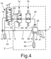
- One in the schematic view of 4 illustrated first embodiment of a relay valve module 3 'of a compressed air brake system differs from the previous version of the relay valve module 3 according to 6 in that a directly controllable switchover valve 74 is now provided instead of the pressure-controlled switchover valve 50, and that a shut-off valve 76 is arranged in the control pressure line 48 leading to the relay valve 26 between the switchover valve 74 and the control pressure inlet 36 of the relay valve 26.
- the switching valve 74 is designed as a clocked controllable 3/2-way solenoid switching valve, by means of which the control pressure line 48 connected to the control pressure input 36 of the relay valve 26 alternates with the brake pressure line 20' connected to the brake pressure connection 7 on the input side or with a brake pressure line 14' connected to the supply pressure line 14'. connected connecting line 54' can be connected.
- the shut-off valve 76 is designed as a clocked controllable 2/2-way solenoid switching valve with a compressed air inlet and a compressed air outlet, by means of which the control pressure present at the control pressure inlet 36 of the relay valve 26 can be included as required.
- the functions of the switching valve 74 and the shut-off valve 76 correspond to those of the relevant valves in the axle valve module 2' according to FIG 1 .
- a pressure sensor 41 is connected to the working pressure outlet 40 of the relay valve 26, the measured values of which can be fed to an electronic control unit (not shown), which controls the directly controlled valves.
- the measured values of the pressure sensor 42 enable pressure control in the sense of a closed pressure control loop.
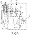
- FIG. 5 One in the schematic view of figure 5 illustrated second embodiment of a relay valve module 3 "of a compressed air brake system differs from the first embodiment of the relay valve module 3 'according to the invention 4 only in that the shut-off valve 78 arranged in the control pressure line 48 leading to the relay valve 26 has the same function as a clocked controllable 3/2-way solenoid switching valve is designed with two compressed air inlets and one compressed air outlet, the second compressed air inlet of which is permanently blocked and has no function.
- the functions of the changeover valve 74 and the shut-off valve 78 correspond to those of the relevant valves in the axle valve module 2" according to FIG 2 .
- the changeover valve 74 and the shut-off valve 78 can be of identical construction at low cost.
Landscapes
- Engineering & Computer Science (AREA)
- Transportation (AREA)
- Mechanical Engineering (AREA)
- Physics & Mathematics (AREA)
- Electromagnetism (AREA)
- Fluid Mechanics (AREA)
- Regulating Braking Force (AREA)
- Valves And Accessory Devices For Braking Systems (AREA)
- Braking Systems And Boosters (AREA)
Description
- Die Erfindung betrifft ein Achsventilmodul einer Druckluftbremsanlage für die Betätigung der Radbremsen einer Fahrzeugachse eines Radfahrzeugs, mit einem Relaisventil, an dessen Steuerdruckeingang eine Steuerdruckleitung angeschlossen ist, die über ein Umschaltventil wechselweise mit einer einen eingesteuerten Bremsdruck führenden Bremsdruckleitung oder mit einer einen Vorratsdruck führenden Vorratsdruckleitung verbindbar ist, und mit jeweils einem ABS-Einlassventil sowie einem ABS-Auslassventil für mindestens einen Radbremszylinder jeder Seite der Fahrzeugachse, welche jeweils als ein druckgesteuertes Membranventil mit einem zugeordneten Vorsteuerventil ausgebildet sind, wobei diese Vorsteuerventile als getaktet steuerbare 3/2-Wege-Magnetschaltventile ausgeführt sind, über die jeweils ein Steuerdruckraum des zugeordneten Membranventils wechselweise mit einem an einer an den Arbeitsdruckausgang des Relaisventils angeschlossenen Achsbremsleitung beziehungsweise an der Steuerdruckleitung des Relaisventils abgegriffenen Steuerdruck oder mit dem Umgebungsdruck beaufschlagbar ist.
- Außerdem ist ein Relaisventilmodul einer Druckluftbremsanlage für die Betätigung von Radbremsen eines Radfahrzeugs offenbart, mit einem Relaisventil, an dessen Steuerdruckeingang eine Steuerdruckleitung angeschlossen ist, die über ein Umschaltventil wechselweise mit einer einen eingesteuerten Bremsdruck führenden Bremsdruckleitung oder mit einer einen Vorratsdruck führenden Vorratsdruckleitung verbindbar ist.
- In der
EP 1 826 085 A2 ist eine Druckluftbremsanlage eines Radfahrzeugs beschrieben, bei der die Steuerventile zur Betätigung der Radbremsen jeder Fahrzeugachse in einem Achsventilmodul zusammengefasst sind. Zumindest das Achsventilmodul der Hinterachse umfasst ein Relaisventil und jeweils ein ABS-Einlassventil sowie ein ABS-Auslassventil für die Radbremszylinder beider Seiten der Hinterachse. Ein weiteres Achsventilmodul ist ausEP 0 547 407 A bekannt. - Bei moderneren Ausführungen eines derartigen Achsventilmoduls der WABCO GmbH sind sowohl das Relaisventil als auch die ABS-Einlassventile und die ABS-Auslassventile jeder Seite der Fahrzeugachse jeweils als eine Membranventileinheit ausgeführt, wie sie beispielsweise aus der
DE 10 2014 012 596 A1 oder derDE 10 2014 012 712 A1 bekannt ist. Jede dieser Membranventileinheiten weist ein Einlassmembranventil und ein Auslassmembranventil auf, bei denen jeweils ein an die jeweilige Membran des betreffenden Membranventils angrenzender Steuerdruckraum über ein zugeordnetes Vorsteuerventil wechselweise mit einem hohen Steuerdruck oder dem Umgebungsdruck beaufschlagbar ist. Die Vorsteuerventile sind als getaktet steuerbare 3/2-Wege-Magnetschaltventile ausgebildet. Bei anliegendem hohem Steuerdruck sind die Membranventile geschlossen. Bei anliegendem Umgebungsdruck sind die Membranventile geöffnet, so dass die Arbeitsdruckausgänge über das jeweilige Einlassmembranventil mit dem betreffenden Arbeitsdruckeingang und über das jeweilige Auslassmembranventil mit einem Entlüftungsausgang verbunden sind. - Um unabhängig von der Betätigung eines Bremspedals durch den Fahrer und der ABS-Steuerung der Radbremsen über die ABS-Einlassventile und die ABS-Auslassventile eine Betätigung der Radbremsen im Rahmen von Fahrsicherheitsfunktionen, wie einer Antriebsschlupfregelung (ASR) beziehungsweise einer automatischen Traktionskontrolle (ATC), einer Kippstabilitätskontrolle (RSC), einer elektronischen Stabilitätskontrolle (ESC) beziehungsweise einem elektronischen Stabilitätsprogramm (ESP) und einer externen Verzögerungsanforderung (XBR), zu ermöglichen, ist dem Steuerdruckeingang des Relaisventils ein Umschaltventil vorgeschaltet, mittels dem dieser wechselweise mit einer einen Bremsdruck führenden Bremsdruckleitung oder mit einer einen Vorratsdruck führenden Vorratsdruckleitung verbindbar ist. Der Bremsdruck wird üblicherweise durch die Betätigung eines Bremspedals über ein mit diesem mechanisch verbundenen Bremspedalventil eingestellt, er kann jedoch bei der Verwendung eines sogenannten elektronischen Bremspedals als Bremswertgeber auch mittels eines elektropneumatischen Bremsventils eingestellt werden. Der Vorratsdruck wird üblicherweise von einer Druckluftversorgungsanlage bereitgestellt und bildet den maximal verfügbaren Bremsdruck.
- Aufgrund von Bauteiltoleranzen bei den ABS-Ventilen und deren Vorsteuerventilen kann es bei bestimmten Funktionen, bei denen die Bremskraft auf beiden Seiten der Fahrzeugachse gleich groß sein soll, wie bei einer elektronischen Bremskraftbegrenzung (EBL) und einer automatischen Notbremsung durch den Bremsassistenten eines Abstandsgeschwindigkeitsregelsystems (ACC), zu unterschiedlich hohen Bremsdrücken in den Radbremszylindern beider Seiten der Fahrzeugachse und damit zur Destabilisierung des Radfahrzeugs kommen.
- Der vorliegenden Erfindung lag daher die Aufgabe zu Grunde, ein Achsventilmodul einer Druckluftbremsanlage der eingangs genannten Bauart auf einfache und kostengünstige Weise derart weiterzubilden, dass im Rahmen bestimmter Fahrsicherheitsfunktionen die Einstellung eines sehr weitgehend exakt gleichen Bremsdruckes in den Radbremszylindern beider Seiten der Fahrzeugachse möglich ist. Des Weiteren ist ein entsprechendes Relaisventilmodul einer Druckluftbremsanlage offenbart, mittels dem die Einstellung eines exakt gleichen Bremsdruckes in den angeschlossenen Radbremszylindern möglich ist, wobei das entsprechende Relaisventil ein Teil des Achsventilmoduls ist, wie z.B. in Anspruch 1 geschrieben worden ist.
- Die das Achsventilmodul betreffende Aufgabe ist in Verbindung mit den Merkmalen des Oberbegriffs des Anspruchs 1 dadurch gelöst, dass in der zum Relaisventil führenden Steuerdruckleitung zwischen dem Umschaltventil und dem Steuerdruckeingang des Relaisventils und zwischen dem Umschaltventil und einem Abzweig der Steuerdruckleitung der ABS-Ventile ein Absperrventil angeordnet ist, mittels dem der an dem Steuerdruckeingang des Relaisventils anliegende Steuerdruck bedarfsweise einschließbar ist.
- Die Erfindung geht von einer bisherigen Ausführung eines Achsventilmoduls einer Druckluftbremsanlage für die Betätigung der Radbremsen einer Fahrzeugachse eines Radfahrzeugs aus, das ein Relaisventil und jeweils ein ABS-Einlassventil und ein ABS-Auslassventil für mindestens einen Radbremszylinder jeder Seite der Fahrzeugachse aufweist. An den Steuerdruckeingang des Relaisventils ist eine Steuerdruckleitung angeschlossen, die über ein Umschaltventil wechselweise mit einer einen eingesteuerten Bremsdruck führenden Bremsdruckleitung oder mit einer einen Vorratsdruck führenden Vorratsdruckleitung verbindbar ist. Die ABS-Einlassventile und die ABS-Auslassventile sind jeweils als ein druckgesteuertes Membranventil mit einem zugeordneten Vorsteuerventil ausgebildet. Die Vorsteuerventile sind als getaktet steuerbare 3/2-Wege-Magnetschaltventile ausgeführt, über die jeweils ein Steuerdruckraum des zugeordneten Membranventils wechselweise mit einem an einer an den Arbeitsdruckausgang des Relaisventils angeschlossenen Achsbremsleitung beziehungsweise an der Steuerdruckleitung des Relaisventils abgegriffenen Steuerdruck oder dem Umgebungsdruck beaufschlagbar ist.
- Durch die Betätigung des Umschaltventils kann ein beliebiger, an dem Steuerdruckeingang des Relaisventils anliegender Steuerdruck, der zwischen dem Bremsdruck in der Bremsdruckleitung und dem Vorratsdruck in der Vorratsdruckleitung liegt, eingestellt sowie durch die Betätigung des Absperrventils eingeschlossen werden. Dieser Bremsdruck wird dann in dem Relaisventil mit entsprechendem Luftvolumendurchsatz auch an dessen Arbeitsdruckausgang eingestellt. Somit liegt dieser Bremsdruck ohne eine Betätigung der im unbetätigten Zustand offenen ABS-Einlassventile und der im unbetätigten Zustand geschlossenen ABS-Auslassventile auch in den Radbremszylindern beider Seiten der Fahrzeugachse vor, so dass die Räder der Fahrzeugachse beidseitig mit identischer Bremskraft abgebremst werden, und eine Destabilisierung des Radfahrzeugs vermieden wird. Der Aufwand zur Ermöglichung dieser symmetrischen Bremsfunktion ist mit dem Einbau des zusätzlichen Absperrventils vergleichsweise gering.
- Das Absperrventil kann als ein getaktet steuerbares 2/2-Wege-Magnetschaltventil mit einem Drucklufteingang und einem Druckluftausgang ausgebildet sein, an die jeweils ein Abschnitt der Steuerdruckleitung des Relaisventils angeschlossen ist, welche im unbetätigten Zustand miteinander verbunden und im betätigten Zustand gegeneinander abgesperrt sind.
- Alternativ dazu kann das Absperrventil auch als ein getaktet steuerbares 3/2-Wege-Magnetschaltventil mit zwei Drucklufteingängen und einem Druckluftausgang ausgebildet sein, dessen erster Drucklufteingang und Druckluftausgang, an die jeweils ein Abschnitt der Steuerdruckleitung des Relaisventils angeschlossen ist, im unbetätigten Zustand miteinander verbunden und im betätigten Zustand gegeneinander abgesperrt sind, und dessen zweiter Drucklufteingang dauerhaft abgesperrt ist.
- Durch die letztgenannte Ausführungsform kann auch vorgesehen sein, dass das Absperrventil baugleich mit den Vorsteuerventilen der ABS-Auslassventile beziehungsweise mit den Vorsteuerventilen der ABS-Einlassventile ausgeführt ist, welches auch fertigungstechnische und logistische Vorteile hat.
- Zur weiteren Vereinfachung des Aufbaus des Achsventilmoduls kann auch vorgesehen sein, dass das Umschaltventil als ein getaktet steuerbares 3/2-Wege-Magnetschaltventil ausgebildet ist, mit einem ersten Drucklufteingang, an den die Bremsdruckleitung angeschlossen ist, mit einem zweiten Drucklufteingang, an den die Vorratsdruckleitung angeschlossen ist, und mit einem Druckluftausgang, an den die Steuerdruckleitung des Relaisventils angeschlossen ist, wobei der erste Drucklufteingang im unbetätigten Zustand mit dem Druckluftausgang verbunden sowie im betätigten Zustand gegenüber diesem abgesperrt ist, und dessen zweiter Drucklufteingang im unbetätigten Zustand gegenüber dem Druckluftausgang abgesperrt sowie im betätigten Zustand mit diesem verbunden ist. Hierdurch kann auch das Umschaltventil baugleich wie das Absperrventil der zweiten Ausführungsform und/oder wie die Vorsteuerventile für die ABS-Auslassventile beziehungsweise wie die Vorsteuerventile für die ABS-Einlassventile ausgeführt sein.
- Die das Relaisventilmodul des Achsventilmoduls betreffende Aufgabe ist in Verbindung mit den Merkmalen des Anspruchs 1 dadurch gelöst, dass in der zum Relaisventil führenden Steuerdruckleitung zwischen dem Umschaltventil und dem Steuerdruckeingang des Relaisventils und zwischen dem Umschaltventil und einem Abzweig einer Steuerdruckleitung von angeschlossenen ABS-Ventilen ein Absperrventil angeordnet ist, mittels dem der an dem Steuerdruckeingang des Relaisventils anliegende Steuerdruck bedarfsweise einschließbar ist.
- Gemäß einem Ausführungsbeispiel ist das Relaisventilmodul eines Achsventilmoduls einer Druckluftbremsanlage für die Betätigung von Radbremsen eines Radfahrzeugs offenbart, das ein Relaisventil aufweist. An den Steuerdruckeingang des Relaisventils ist eine Steuerdruckleitung angeschlossen, die über ein Umschaltventil wechselweise mit einer einen eingesteuerten Bremsdruck führenden Bremsdruckleitung oder mit einer einen Vorratsdruck führenden Vorratsdruckleitung verbindbar ist.
- Beim erfindungsgemäßen Achsventilmodul kann vorteilhaft vorgesehen sein, dass an den Arbeitsdruckausgang des Relaisventils ein Drucksensor angeschlossen ist, dessen Messwerte einem elektronischen Steuergerät zuleitbar sind, welches die erwähnten direkt, also elektrisch gesteuerten Ventile ansteuert. Die Messwerte dieses Drucksensors ermöglichen eine Druckregelung in Sinne einer geschlossenen Druckregelschleife.
- Zur weiteren Verdeutlichung der Erfindung ist der Beschreibung eine Zeichnung mit mehreren Ausführungsbeispielen beigefügt. In dieser Zeichnung zeigt
-
Fig. 1 den Aufbau einer ersten Ausführungsform eines erfindungsgemäßen Achsventilmoduls in einer schematischen Ansicht, -
Fig. 2 den Aufbau einer zweiten Ausführungsform eines erfindungsgemäßen Achsventilmoduls in einer schematischen Ansicht, -
Fig. 3 den Aufbau einer bisherigen Ausführung eines Achsventilmoduls in einer schematischen Ansicht, -
Fig. 4 den Aufbau einer ersten Ausführungsform eines Relaisventilmoduls in einer schematischen Ansicht, -
Fig. 5 den Aufbau einer zweiten Ausführungsform eines Relaisventilmoduls in einer schematischen Ansicht, -
Fig. 6 den Aufbau einer bisherigen Ausführung eines Relaisventilmoduls in einer schematischen Ansicht. - In der schematischen Ansicht von
Fig. 3 ist eine bekannte Ausführungsform eines Achsventilmoduls 2 einer Druckluftbremsanlage für die Betätigung der Radbremsen einer Fahrzeugachse eines Radfahrzeugs dargestellt. Das Achsventilmodul 2 weist einen Vorratsdruckanschluss 4, einen eingangsseitigen Bremsdruckanschluss 6, einen ersten ausgangsseitigen Bremsdruckanschluss 8 für mindestens einen Radbremszylinder einer Radbremse für die linke Seite der Fahrzeugachse und einen zweiten ausgangsseitigen Bremsdruckanschluss 10 für mindestens einen Radbremszylinder einer Radbremse für die rechte Seite der Fahrzeugachse auf. - Eine an den Vorratsdruckanschluss 4 angeschlossene erste Vorratsdruckleitung 14 führt einen von einer Druckluftquelle 12 bereitgestellten Vorratsdruck. Eine an den eingangsseitigen Bremsdruckanschluss 8 angeschlossene Bremsdruckleitung 20 führt einen Bremsdruck, der durch eine über ein Bremspedalventil 18 kontinuierlich verstellbare Verbindung zwischen einer an die Druckluftquelle 12 angeschlossenen zweiten Vorratsdruckleitung 16 oder einer über einen Schalldämpfer 24 in die Umgebung führenden Entlüftungsleitung 22 einstellbar ist.
- Das Achsventilmodul 2 umfasst ein Relaisventil 26 und jeweils ein ABS-Einlassventil 28, 32 sowie jeweils ein ABS-Auslassventil 30, 34 für mindestens einen Radbremszylinder einer Radbremse jeder Seite der Fahrzeugachse. Das Relaisventil 26 weist einen Steuerdruckeingang 36, einen Arbeitsdruckeingang 38, einen Arbeitsdruckausgang 40 und einen Entlüftungsausgang 42 auf. Der Arbeitsdruckeingang 38 ist über eine Vorratsdruckleitung 14' mit dem Vorratsdruckanschluss 4 verbunden. Der Entlüftungsausgang 42 steht über eine Entlüftungsleitung 44 und einen Schalldämpfer 46 mit der Umgebung in Verbindung.
- An den Arbeitsdruckausgang 40 des Relaisventils 26 ist ein Drucksensor 41 angeschlossen, dessen Messwerte einem nicht dargestellten elektronischen Steuergerät zuleitbar sind, welches die direkt gesteuerten Ventile ansteuert. Die Messwerte des Drucksensors 41 ermöglichen eine Druckregelung in Sinne einer geschlossenen Druckregelschleife.
- Eine an den Steuerdruckeingang 36 angeschlossene Steuerdruckleitung 48 ist über ein als ein druckgesteuertes 3/2-Wege-Schaltventil ausgebildetes Umschaltventil 50 und ein diesem zugeordnetes, als ein getaktet steuerbares 3/2-Wege-Magnetschaltventil ausgebildetes Vorsteuerventil 52 wechselweise mit einer an den eingangsseitigen Bremsdruckanschluss 6 angeschlossenen Bremsdruckleitung 20' oder der Vorratsdruckleitung 14' verbindbar.
- Über das Vorsteuerventil 52 sind der Steuerdruckeingang 36 und ein erster Arbeitsdruckeingang des Umschaltventils 50 wechselweise mit der Umgebung oder über eine Verbindungsleitung 54 mit der Vorratsdruckleitung 14' verbindbar. Im unbetätigten, also unbestromten Zustand des Vorsteuerventils 52 ist die Steuerdruckleitung 48 des Relaisventils 26 über das Umschaltventil 50 mit der Bremsdruckleitung 20' verbunden. Im betätigten, also bestromten Zustand des Vorsteuerventils 52 ist die Steuerdruckleitung 48 des Relaisventils 26 über das Umschaltventil 50, das Vorsteuerventil 52 und die Verbindungsleitung 54 mit der Vorratsdruckleitung 14' verbunden. In dem Relaisventil 26 wird somit an dem Arbeitsdruckausgang 40 abhängig von dem Schaltzustand des Umschaltventils 50 mit entsprechendem Luftvolumendurchsatz entweder der über das Bremspedalventil 18 in die Bremsdruckleitung 20, 20' eingesteuerte Bremsdruck oder der in der Vorratsdruckleitung 14' anliegende Vorratsdruck eingestellt. Der Bremsdruck wird an dem Arbeitsdruckausgang 40 des Relaisventils 26 im normalen Fahrbetrieb, insbesondere bei betätigtem Bremspedalventil 18, eingestellt. Der Vorratsdruck wird an dem Arbeitsdruckausgang 40 des Relaisventils 26, insbesondere bei nicht betätigtem Bremspedalventil 18, dann eingestellt, wenn eine aktivierte Fahrsicherheitsfunktion, wie die der eingangs genannten Systeme ASR/ATC, RSC oder ESC/ESP, eine individuelle Betätigung der Radbremsen erfordert.
- An den Arbeitsdruckausgang 40 des Relaisventils 26 ist eine Achsbremsleitung 56 angeschlossen, deren Zweige 56a, 56b eingangsseitig an die ABS-Einlassventile 28, 32 angeschlossen sind. Ausgangsseitig ist an den ABS-Einlassventilen 28, 32 jeweils eine zu dem jeweiligen ausgangsseitigen Bremsdruckanschluss 8, 10 führende Radbremsleitung 58, 60 an die ABS-Einlassventile 28, 32 angeschlossen. Mittels der ABS-Einlassventile 28, 32, die vorliegend als druckgesteuerte 2/2-Wege-Membranventile ausgebildet sind, können die Radbremsleitungen 58, 60 wechselweise mit dem jeweiligen Zweig 56a, 56b der Achsbremsleitung 56 verbunden oder gegenüber diesem abgesperrt werden.
- Den ABS-Einlassventilen 28, 32 ist jeweils ein als ein getaktet steuerbares 3/2-Wege-Magnetschaltventil ausgebildetes Vorsteuerventil 62, 66 zugeordnet. Über diese Vorsteuerventile 62, 66 ist der jeweilige Steuerdruckeingang der ABS-Einlassventile 28, 32 wechselweise mit dem Umgebungsdruck oder mit einem über eine verzweigte Steuerdruckleitung 70 an der Achsbremsleitung 56 abgegriffenen Steuerdruck beaufschlagbar. Im unbetätigten, also unbestromten Zustand dieser Vorsteuerventile 62, 66 sind die ABS-Einlassventile 28, 32 geöffnet, so dass die Zweige 56a, 56b der Achsbremsleitung 56 mit den Radbremsleitungen 58, 60 verbunden sind, auch wenn die ABS-Einlassventile 28, 32 aufgrund ihrer Membranbauweise in
Fig. 3 geschlossen dargestellt sind. Im betätigten, also bestromten Zustand der Vorsteuerventile 62, 66 sind die ABS-Einlassventile 28, 32 geschlossen, so dass die Radbremsleitungen 58, 60 dann gegenüber den Zweigen 56a, 56b der Achsbremsleitung 56 abgesperrt sind. - An die Entlüftungsleitung 44 des Relaisventils 26 ist eine weitere Entlüftungsleitung 72 angeschlossen, deren Zweige 72a, 72b eingangsseitig an jeweils ein zugeordnetes ABS-Auslassventil 30, 34 angeschlossen sind. Ausgangsseitig ist jeweils die zu dem jeweiligen ausgangsseitigen Bremsdruckanschluss 8, 10 führende Radbremsleitung 58, 60 an die ABS-Auslassventile 30, 34 angeschlossen. Über die ABS-Auslassventile 30, 34, die ebenfalls als druckgesteuerte 2/2-Wege-Membranventile ausgebildet sind, können die Radbremsleitungen 58, 60 wechselweise mit dem jeweiligen Zweig 72a, 72b der Entlüftungsleitung 72 verbunden oder gegenüber diesem abgesperrt werden.
- Den ABS-Auslassventilen 30, 34 ist jeweils ein als ein getaktet steuerbares 3/2-Wege-Magnetschaltventil ausgebildetes Vorsteuerventil 64, 68 zugeordnet. Über diese Vorsteuerventile 64, 68 ist der jeweilige Steuerdruckeingang der ABS-Auslassventile 30, 34 wechselweise mit dem über die verzweigte Steuerdruckleitung 70 an der Steuerdruckleitung 48 des Relaisventils 26 abgegriffenen Steuerdruck oder dem Umgebungsdruck beaufschlagbar. Im unbetätigten, also unbestromten Zustand dieser Vorsteuerventile 64, 68 sind die ABS-Auslassventile 30, 34 geschlossen, so dass die Radbremsleitungen 58, 60 gegenüber den Zweigen 72a, 72b der Entlüftungsleitung 72 abgesperrt sind. Im betätigten, also bestromten Zustand der Vorsteuerventile 64, 68 sind die ABS-Auslassventile 30, 34 geöffnet, so dass die Radbremsleitungen 58, 60 dann über die Zweige 72a, 72b der Entlüftungsleitung 72 entlüftet werden.
- In einer dazu alternativen Anordnung kann der Steuerdruck für die ABS-Ventile 28, 30, 32, 34 auch zwischen dem Umschaltventil 50 und dem Steuerdruckeingang 36 an der zum Relaisventil 26 führenden Steuerdruckleitung 48 abgegriffen werden. Zur Verdeutlichung dieser alternativen Anschlussvariante ist der eingangsseitige Zweig der Steuerdruckleitung 70' gestrichelt dargestellt.
- Eine in der schematischen Ansicht von
Fig. 1 abgebildete erste Ausführungsform eines erfindungsgemäßen Achsventilmoduls 2' einer Druckluftbremsanlage unterscheidet sich von der bekannten Ausführung des Achsventilmoduls 2 gemäßFig. 3 dadurch, dass nun anstelle des druckgesteuerten Umschaltventils 50 ein direkt ansteuerbares Umschaltventil 74 vorgesehen ist, und dass in der zum Relaisventil 26 führenden Steuerdruckleitung 48 zwischen dem Umschaltventil 74 und dem Steuerdruckeingang 36 des Relaisventils 26 beziehungsweise dem Abzweig der zu den ABS-Ventilen 28, 30, 32, 34 führenden Steuerdruckleitung 70' ein Absperrventil 76 angeordnet ist. - Das Umschaltventil 74 ist nun als ein getaktet steuerbares 3/2-Wege-Magnetschaltventil ausgebildet, mittels dem die an den Steuerdruckeingang 36 des Relaisventils 26 angeschlossene Steuerdruckleitung 48 wechselweise mit der an den eingangsseitigen Bremsdruckanschluss 6 angeschlossenen Bremsdruckleitung 20' oder mit einer an die Vorratsdruckleitung 14' angeschlossenen Verbindungsleitung 54' verbindbar ist. Im unbetätigten, also unbestromten Zustand des Umschaltventils 74 ist die Steuerdruckleitung 48 des Relaisventils 26 mit der Bremsdruckleitung 20' verbunden. Im betätigten, also bestromten Zustand des Umschaltventils 74 ist die Steuerdruckleitung 48 des Relaisventils 26 über die Verbindungsleitung 54' mit der Vorratsdruckleitung 14' verbunden. Das Umschaltventil 74 ist vorteilhaft baugleich mit den Vorsteuerventilen 64, 68 für die ABS-Auslassventile 30, 34 ausgeführt, welches fertigungstechnische und logistische Vorteilen hat.
- Das Absperrventil 76 ist als ein getaktet steuerbares 2/2-Wege-Magnetschaltventil mit einem Drucklufteingang und einem Druckluftausgang ausgebildet, mittels dem der an dem Steuerdruckeingang 36 des Relaisventils 26 anliegende Steuerdruck bedarfsweise einschließbar ist. Im unbetätigten, also unbestromten Zustand des Absperrventils 76 sind der Drucklufteingang und der Druckluftausgang, an die jeweils ein Abschnitt der Steuerdruckleitung 48 des Relaisventils 26 angeschlossen ist, miteinander verbunden. Im betätigten, also bestromten Zustand des Absperrventils 76 sind der Drucklufteingang und der Druckluftausgang gegeneinander abgesperrt.
- Durch die Betätigung des Umschaltventils 74 kann ein beliebiger, an dem Steuerdruckeingang 36 des Relaisventils 26 anliegender Steuerdruck, der zwischen dem Bremsdruck in der Bremsdruckleitung 20, 20' und dem Vorratsdruck in der Vorratsdruckleitung 14, 14' liegt, eingestellt und durch die Betätigung des Absperrventils 76 eingeschlossen werden. Dieser Bremsdruck wird dann in dem Relaisventil 26 mit entsprechendem Luftvolumendurchsatz auch an dessen Arbeitsdruckausgang 40 eingestellt. Somit liegt dieser Bremsdruck ohne eine Betätigung der im unbetätigten Zustand offenen ABS-Einlassventile 28, 32 und der im unbetätigten Zustand geschlossenen ABS-Auslassventile 30, 34 auch in den Radbremszylindern beider Seiten der Fahrzeugachse vor, so dass die Räder der Fahrzeugachse beidseitig mit identischer Bremskraft abgebremst werden, und eine Destabilisierung des Radfahrzeugs vermieden wird. Der Aufwand zur Ermöglichung dieser symmetrischen Bremsfunktion ist mit dem Einbau des zusätzlichen Absperrventils 76 sehr gering.
- Eine in der schematischen Ansicht von
Fig. 2 abgebildete zweite Ausführungsform des erfindungsgemäßen Achsventilmoduls 2" einer Druckluftbremsanlage unterscheidet sich von dem ersten Ausführungsbeispiel des erfindungsgemäßen Achsventilmoduls 2' gemäßFig. 1 nur dadurch, dass das in der Steuerdruckleitung 48 des Relaisventils 26 angeordnete Absperrventil 78 bei gleicher Funktion als ein getaktet steuerbares 3/2-Wege-Magnetschaltventil mit zwei Drucklufteingängen und einem Druckluftausgang ausgebildet ist. - Im unbetätigten, also unbestromten Zustand des Absperrventils 78 sind der erste Drucklufteingang und der Druckluftausgang, an die jeweils ein Abschnitt der Steuerdruckleitung 48 des Relaisventils 26 angeschlossen ist, miteinander verbunden. Im betätigten, also bestromten Zustand des Absperrventils 78 sind der erste Drucklufteingang und der Druckluftausgang gegeneinander abgesperrt. Der zweite Drucklufteingang des Absperrventils 78 ist dauerhaft abgesperrt und ohne Funktion. Durch die Verwendung eines derartigen 3/2-Wege-Magnetschaltventils für die Absperrfunktion kann auch das Absperrventil 78 kostengünstig baugleich wie die Vorsteuerventile 64, 68 der ABS-Auslassventile 30, 34 und das Umschaltventil 74 ausgeführt werden.
- In der schematischen Darstellung der
Fig. 6 ist eine bekannte Ausführungsform eines Relaisventilmoduls 3 einer Druckluftbremsanlage für die Betätigung von Radbremsen eines Radfahrzeugs dargestellt. Das Relaisventilmodul 3 weist einen Vorratsdruckanschluss 5, einen eingangsseitigen Bremsdruckanschluss 7 sowie einen ausgangsseitigen Bremsdruckanschluss 9 auf. - Eine an den Vorratsdruckanschluss 5 angeschlossene erste Vorratsdruckleitung 14 führt einen von einer Druckluftquelle 12 bereitgestellten Vorratsdruck. Eine an den eingangsseitigen Bremsdruckanschluss 9 angeschlossene Bremsdruckleitung 20 führt einen Bremsdruck, der durch eine über ein Bremspedalventil 18 kontinuierlich verstellbare Verbindung zwischen einer an die Druckluftquelle 12 angeschlossenen zweiten Vorratsdruckleitung 16 oder einer über einen Schalldämpfer 24 in die Umgebung führenden Entlüftungsleitung 22 einstellbar ist. Der ausgangsseitige Bremsdruckanschluss 9 steht über eine Bremsdruckleitung 55 mit dem Arbeitsdruckausgang 40 des Relaisventils 26 in Verbindung. Der Aufbau und die Anordnung des Relaisventils 26 und des Umschaltventils 50 sowie dessen Vorsteuerventils 52 entsprechen denjenigen in dem bekannten Achsventilmodul 2 gemäß
Fig. 3 , so dass hier gleiche Bezugszeichen verwendet werden und auf eine weitere Beschreibung verzichtet wird. - Eine in der schematischen Ansicht von
Fig. 4 abgebildete erste Ausführungsform eines Relaisventilmoduls 3' einer Druckluftbremsanlage unterscheidet sich von der bisherigen Ausführung des Relaisventilmoduls 3 gemäßFig. 6 dadurch, dass nun anstelle des druckgesteuerten Umschaltventils 50 ein direkt ansteuerbares Umschaltventil 74 vorgesehen ist, und dass in der zum Relaisventil 26 führenden Steuerdruckleitung 48 zwischen dem Umschaltventil 74 und dem Steuerdruckeingang 36 des Relaisventils 26 ein Absperrventil 76 angeordnet ist. - Das Umschaltventil 74 ist als ein getaktet steuerbares 3/2-Wege-Magnetschaltventil ausgebildet, mittels dem die an den Steuerdruckeingang 36 des Relaisventils 26 angeschlossene Steuerdruckleitung 48 wechselweise mit der an den eingangsseitigen Bremsdruckanschluss 7 angeschlossenen Bremsdruckleitung 20' oder mit einer an die Vorratsdruckleitung 14' angeschlossenen Verbindungsleitung 54' verbindbar ist. Das Absperrventil 76 ist als ein getaktet steuerbares 2/2-Wege-Magnetschaltventil mit einem Drucklufteingang und einem Druckluftausgang ausgebildet, mittels dem der an dem Steuerdruckeingang 36 des Relaisventils 26 anliegende Steuerdruck bedarfsweise einschließbar ist. Die Funktionen des Umschaltventils 74 und des Absperrventils 76 entsprechen denjenigen der betreffenden Ventile in dem Achsventilmodul 2' gemäß
Fig. 1 . - Auch bei diesem Relaisventilmoduls 3' ist an den Arbeitsdruckausgang 40 des Relaisventils 26 ist ein Drucksensor 41 angeschlossen, dessen Messwerte einem nicht dargestellten elektronischen Steuergerät zuleitbar sind, welches die direkt gesteuerten Ventile ansteuert. Die Messwerte des Drucksensors 42 ermöglichen eine Druckregelung in Sinne einer geschlossenen Druckregelschleife.
- Eine in der schematischen Ansicht von
Fig. 5 abgebildete zweite Ausführungsform eines Relaisventilmoduls 3" einer Druckluftbremsanlage unterscheidet sich von dem ersten Ausführungsbeispiel des erfindungsgemäßen Relaisventilmoduls 3' gemäßFig. 4 nur dadurch, dass das in der zum Relaisventil 26 führenden Steuerdruckleitung 48 angeordnete Absperrventil 78 bei gleicher Funktion als ein getaktet steuerbares 3/2-Wege-Magnetschaltventil mit zwei Drucklufteingängen und einem Druckluftausgang ausgebildet ist, dessen zweiter Drucklufteingang dauerhaft abgesperrt und ohne Funktion ist. Die Funktionen des Umschaltventils 74 und des Absperrventils 78 entsprechen denjenigen der betreffenden Ventile in dem Achsventilmodul 2" gemäßFig. 2 . Durch die Verwendung eines derartigen 3/2-Wege-Magnetschaltventils für die Absperrfunktion können das Umschaltventil 74 und das Absperrventil 78 kostengünstig baugleich ausgebildet sein. -
- 2
- Achsventilmodul (bisherige Ausführungsform)
- 2'
- Achsventilmodul (erste erfindungsgemäße Ausführungsform)
- 2"
- Achsventilmodul (zweite erfindungsgemäße Ausführungsform)
- 3
- Relaisventilmodul (bisherige Ausführungsform)
- 3'
- Relaisventilmodul (erste Ausführungsform)
- 3"
- Relaisventilmodul (zweite Ausführungsform)
- 4
- Erster Vorratsdruckanschluss
- 5
- Zweiter Vorratsdruckanschluss
- 6
- Eingangsseitiger Bremsdruckanschluss
- 7
- Eingangsseitiger Bremsdruckanschluss
- 8
- Erster ausgangsseitiger Bremsdruckanschluss
- 9
- Ausgangsseitiger Bremsdruckanschluss
- 10
- Zweiter ausgangsseitiger Bremsdruckanschluss
- 12
- Druckluftquelle
- 14, 14'
- Erste Vorratsdruckleitung
- 16
- Zweite Vorratsdruckleitung
- 18
- Bremspedalventil
- 20, 20'
- Bremsdruckleitung
- 22
- Entlüftungsleitung
- 24
- Erster Schalldämpfer
- 26
- Relaisventil
- 28
- Erstes ABS-Einlassventil
- 30
- Erstes ABS-Auslassventil
- 32
- Zweites ABS-Einlassventil
- 34
- Zweites ABS-Auslassventil
- 36
- Steuerdruckeingang
- 38
- Arbeitsdruckeingang
- 40
- Arbeitsdruckausgang
- 41
- Drucksensor am Arbeitsdruckausgang
- 42
- Entlüftungsausgang
- 44
- Entlüftungsleitung
- 46
- Zweiter Schalldämpfer
- 48
- Steuerdruckleitung
- 50
- Umschaltventil, druckgesteuertes 3/2-Wege-Schaltventil
- 52
- Vorsteuerventil, 3/2-Wege-Magnetschaltventil
- 54, 54'
- Verbindungsleitung
- 55
- Bremsdruckleitung
- 56
- Achsbremsleitung
- 56a, 56b
- Zweige der Achsbremsleitung 56
- 58
- Radbremsleitung (linke Seite)
- 60
- Radbremsleitung (rechte Seite)
- 62
- Vorsteuerventil, 3/2-Wege-Magnetschaltventil
- 64
- Vorsteuerventil, 3/2-Wege-Magnetschaltventil
- 66
- Vorsteuerventil, 3/2-Wege-Magnetschaltventil
- 68
- Vorsteuerventil, 3/2-Wege-Magnetschaltventil
- 70, 70'
- Steuerdruckleitung
- 72
- Entlüftungsleitung
- 72a, 72b
- Zweige der Entlüftungsleitung 72
- 74
- Umschaltventil, 3/2-Wege-Magnetschaltventil
- 76
- Absperrventil, 2/2-Wege-Magnetschaltventil
- 78
- Absperrventil, 3/2-Wege-Magnetschaltventil
Claims (4)
- Achsventilmodul (2', 2") einer Druckluftbremsanlage für die Betätigung der Radbremsen einer Fahrzeugachse eines Radfahrzeugs, mit einem Relaisventil (26), an dessen Steuerdruckeingang (36) eine Steuerdruckleitung (48) angeschlossen ist, die über ein Umschaltventil (50, 74) wechselweise mit einer einen eingesteuerten Bremsdruck führenden Bremsdruckleitung (20, 20') oder mit einer einen Vorratsdruck führenden Vorratsdruckleitung (14, 14') verbindbar ist, und mit jeweils einem ABS-Einlassventil (28, 32) sowie einem ABS-Auslassventil (30, 34) für mindestens einen Radbremszylinder jeder Seite der Fahrzeugachse, welche jeweils als ein druckgesteuertes Membranventil mit einem zugeordneten Vorsteuerventil (62, 64, 66, 68) ausgebildet sind, wobei diese Vorsteuerventile (62, 64, 66, 68) als getaktet steuerbare 3/2-Wege-Magnetschaltventile ausgeführt sind, über die jeweils ein Steuerdruckraum des zugeordneten Membranventils (28, 30, 32, 34) wechselweise mit einem an einer an den Arbeitsdruckausgang (40) des Relaisventils (26) angeschlossenen Achsbremsleitung (56) beziehungsweise an der Steuerdruckleitung (48) des Relaisventils (26) abgegriffenen Steuerdruck oder mit dem Umgebungsdruck beaufschlagbar ist, wobei in der zum Relaisventil (26) führenden Steuerdruckleitung (48) zwischen dem Umschaltventil (50, 74) und dem Steuerdruckeingang (36) des Relaisventils (26) und zwischen dem Umschaltventil (50, 74) und einem Abzweig einer Steuerdruckleitung (70') der ABS-Ventile (28, 30, 32, 34) ein Absperrventil (76, 78) angeordnet ist, mittels dem der an dem Steuerdruckeingang (36) des Relaisventils (26) anliegende Steuerdruck bedarfsweise einschließbar ist, und wobei das Absperrventil (76) als ein getaktet steuerbares 2/2-Wege-Magnetschaltventil mit einem Drucklufteingang und einem Druckluftausgang ausgebildet ist, an die jeweils ein Abschnitt der Steuerdruckleitung (48) des Relaisventils (26) angeschlossen ist, welche im unbetätigten Zustand miteinander verbunden sowie im betätigten Zustand gegeneinander abgesperrt sind.
- Achsventilmodul nach Anspruch 1, dadurch gekennzeichnet, dass das Umschaltventil (74) als ein getaktet steuerbares 3/2-Wege-Magnetschaltventil ausgebildet ist, mit einem ersten Drucklufteingang, an den die Bremsdruckleitung (20') angeschlossen ist, mit einem zweiten Drucklufteingang, an den die Vorratsdruckleitung (14') angeschlossen ist, und mit einem Druckluftausgang, an den die Steuerdruckleitung (48) des Relaisventils (26) angeschlossen ist, wobei der erste Drucklufteingang im unbetätigten Zustand mit dem Druckluftausgang verbunden sowie im betätigten Zustand gegenüber diesem abgesperrt ist, und dessen zweiter Drucklufteingang im unbetätigten Zustand gegenüber dem Druckluftausgang abgesperrt und im betätigten Zustand mit diesem verbunden ist.
- Achsventilmodul nach Anspruch 1 oder 2, dadurch gekennzeichnet, dass das Umschaltventil (74) baugleich mit dem Absperrventil (78) und/oder den Vorsteuerventilen (64, 68) der ABS-Auslassventile (30, 34) beziehungsweise den Vorsteuerventilen (62, 66) der ABS-Einlassventile (28, 32) ausgeführt ist.
- Achsventilmodul nach einem der vorherigen Ansprühe, dadurch gekennzeichnet, dass an den Arbeitsdruckausgang (40) des Relaisventils (26) ein Drucksensor (41) angeschlossen ist, dessen Messwerte einem elektronischen Steuergerät zuleitbar sind, welches die direkt gesteuerten Ventile ansteuert.
Applications Claiming Priority (2)
| Application Number | Priority Date | Filing Date | Title |
|---|---|---|---|
| DE102017009954.5A DE102017009954A1 (de) | 2017-10-26 | 2017-10-26 | Achsventilmodul und Relaisventilmodul einer Druckluftbremsanlage |
| PCT/EP2018/073624 WO2019081101A1 (de) | 2017-10-26 | 2018-09-03 | Achsventilmodul und relaisventilmodul einer druckluftbremsanlage |
Publications (2)
| Publication Number | Publication Date |
|---|---|
| EP3700788A1 EP3700788A1 (de) | 2020-09-02 |
| EP3700788B1 true EP3700788B1 (de) | 2023-05-10 |
Family
ID=63528733
Family Applications (1)
| Application Number | Title | Priority Date | Filing Date |
|---|---|---|---|
| EP18766171.5A Active EP3700788B1 (de) | 2017-10-26 | 2018-09-03 | Achsventilmodul und relaisventilmodul einer druckluftbremsanlage |
Country Status (5)
| Country | Link |
|---|---|
| US (1) | US11511719B2 (de) |
| EP (1) | EP3700788B1 (de) |
| CN (1) | CN111247044B (de) |
| DE (1) | DE102017009954A1 (de) |
| WO (1) | WO2019081101A1 (de) |
Families Citing this family (7)
| Publication number | Priority date | Publication date | Assignee | Title |
|---|---|---|---|---|
| DE102019127129A1 (de) | 2019-10-09 | 2021-04-15 | WABCO Global GmbH | Arbeitsfahrzeug für den Einsatz in der Landwirtschaft und Verfahren zu dessen Steuerung |
| CN110803147A (zh) * | 2019-11-27 | 2020-02-18 | 一汽解放汽车有限公司 | 一种气制动系统及其制动方法 |
| DE102019134843A1 (de) * | 2019-12-18 | 2021-06-24 | Voith Patent Gmbh | Steuerluftsystem für einen hydrodynamischen Retarder |
| CN113479180A (zh) * | 2021-07-19 | 2021-10-08 | 武汉理工大学 | 适于商用车多层级驾驶自动化的自动调压阀及控制方法 |
| CN113548027B (zh) * | 2021-09-18 | 2022-03-04 | 天津所托瑞安汽车科技有限公司 | 一种转向桥的制动压力控制模块及控制方法 |
| EP4405220B1 (de) * | 2021-09-24 | 2025-10-29 | ETO MAGNETIC GmbH | Pneumatische steuervorrichtung für eine hydrodynamische bremse |
| GB2622385A (en) * | 2022-09-14 | 2024-03-20 | Knorr Bremse Systeme Fuer Nutzfahrzeuge Gmbh | Relay valve arrangement for a trailer brake system |
Family Cites Families (13)
| Publication number | Priority date | Publication date | Assignee | Title |
|---|---|---|---|---|
| DE3730779C2 (de) * | 1987-09-12 | 1997-07-03 | Wabco Gmbh | Magnetgesteuerte Ventileinrichtung |
| DE4141995A1 (de) * | 1991-12-19 | 1993-06-24 | Bosch Gmbh Robert | Druckluft-bremsanlage, insbesondere fuer nutzfahrzeuge |
| DE4309467A1 (de) * | 1993-03-24 | 1994-09-29 | Bosch Gmbh Robert | Relaisventil-Baugruppe für die belagverschleißabhängige Bremsdrucksteuerung |
| DE10156673A1 (de) * | 2001-11-17 | 2003-05-28 | Wabco Gmbh & Co Ohg | Verfahren zum Betrieb einer elektrisch gesteuerten Druckmittelbremsanlage |
| DE10341723C5 (de) * | 2003-09-10 | 2013-06-27 | Knorr-Bremse Systeme für Nutzfahrzeuge GmbH | Luftaufbereitungsanlage und Verfahren zum sicheren Lösen einer Feststellbremsanlage |
| DE102005060225A1 (de) * | 2005-12-16 | 2007-06-21 | Wabco Gmbh | Elektropneumatische Bremssteuerungseinrichtung |
| US7658453B2 (en) | 2006-02-16 | 2010-02-09 | Meritor Wabco Vehicle Control Systems | Service brake relay with integrated quick release valve |
| DE102008014547A1 (de) * | 2008-03-15 | 2009-09-17 | Wabco Gmbh | Bremsanlage für ein Fahrzeug |
| DE102010010606B4 (de) * | 2010-03-08 | 2015-02-19 | Knorr-Bremse Systeme für Nutzfahrzeuge GmbH | Modular aufgebaute Drucksteuervorrichtung einer Druckmittel-Bremsanlage eines Fahrzeugs |
| DE102010050580A1 (de) * | 2010-11-05 | 2012-05-10 | Wabco Gmbh | Ventileinrichtung, Bremsanlage und Fahrzeug |
| DE102014012712A1 (de) | 2014-08-27 | 2016-03-03 | Wabco Gmbh | Ventileinheit zur Druckmodulation in einer Druckluft-Bremsanlage |
| DE102014012596A1 (de) | 2014-08-27 | 2016-03-03 | Wabco Gmbh | Ventileinheit zur Druckmodulation in einer Druckluft-Bremsanlage |
| US10150457B2 (en) * | 2016-04-28 | 2018-12-11 | Bendix Commercial Vehicle Systems Llc | Valve module for an air braking system of a heavy vehicle |
-
2017
- 2017-10-26 DE DE102017009954.5A patent/DE102017009954A1/de not_active Withdrawn
-
2018
- 2018-09-03 WO PCT/EP2018/073624 patent/WO2019081101A1/de not_active Ceased
- 2018-09-03 US US16/757,781 patent/US11511719B2/en active Active
- 2018-09-03 EP EP18766171.5A patent/EP3700788B1/de active Active
- 2018-09-03 CN CN201880068496.2A patent/CN111247044B/zh active Active
Also Published As
| Publication number | Publication date |
|---|---|
| CN111247044A (zh) | 2020-06-05 |
| US11511719B2 (en) | 2022-11-29 |
| CN111247044B (zh) | 2022-06-03 |
| EP3700788A1 (de) | 2020-09-02 |
| WO2019081101A1 (de) | 2019-05-02 |
| DE102017009954A1 (de) | 2019-05-02 |
| US20210188235A1 (en) | 2021-06-24 |
Similar Documents
| Publication | Publication Date | Title |
|---|---|---|
| EP3849860B1 (de) | Relaisventilmodul zur verwendung als achsmodulator und anhängersteuermodul | |
| EP2544932B1 (de) | Modular aufgebaute drucksteuervorrichtung einer druckmittel-bremsanlage eines fahrzeugs | |
| EP3183148B1 (de) | Verfahren zum steuern einer betriebsbremseinrichtung eines fahrzeugs sowie betriebsbremsventileinrichtung für eine solche betriebsbremseinrichtung | |
| EP2059429B2 (de) | Ventileinheit für eine elektropneumatische bremssteuerungseinrichtung | |
| EP3292030B1 (de) | Vorrichtung zum steuern einer bremsanlage für ein nutzfahrzeug und bremsanlage | |
| EP2133250B1 (de) | Parkbremsventilanordnung für ein Bremssystem eines Nutzfahrzeuges | |
| EP4069559B1 (de) | Monostabil und fehlertolerant ausgelegte feststellbremsventilanordnung | |
| DE102015112490B4 (de) | Elektro-pneumatische Steuereinrichtung einer elektro-pneumatischen Bremsanlage einer Zugfahrzeug-Anhängerkombination | |
| EP3700788A1 (de) | Achsventilmodul und relaisventilmodul einer druckluftbremsanlage | |
| EP2055542A1 (de) | Druckmittelbetätigte Bremseinrichtung eines Zugfahrzeugs mit einem gegenläufige Drücke für Anhängerbremsen erzeugenden Festellbremsmodul | |
| WO2010031563A1 (de) | Feststellbremsanlage | |
| DE102014118943A1 (de) | Verfahren zur Steuerung einer elektropneumatischen Parkbremseinrichtung mit dynamischer Blockierverhinderung | |
| EP3010772B1 (de) | Steuereinrichtung zur steuerung der bremsen einer zugfahrzeug-anhängerkombination | |
| DE102011012270A1 (de) | Antriebsschlupfgeregelte Bremsanlage eines Haltestellen anfahrenden Kraftfahrzeugs | |
| EP4440893A1 (de) | Ausfallsicheres redundantes bremssystem mit druckeinspeisung über einen entlüftungspfad des primären modulators | |
| EP3286052B1 (de) | Parkbremseinrichtung für kraftfahrzeuge | |
| EP3277551B1 (de) | Drucklufteinrichtung für fahrzeuge mit doppelrelaisventil | |
| DE102012105136A1 (de) | Steuereinrichtung zur Steuerung der Bremsen einer Zugfahrzeug-Anhängerkombination | |
| EP3055175B1 (de) | Verfahren zum steuern einer drucksteuervorrichtung einer druckmittel-bremsanlage eines fahrzeugs | |
| EP1275570B1 (de) | Bremsanlage mit elektropneumatischem Modulator | |
| EP3860892B1 (de) | Abs-drucksteuerventilanordnung | |
| EP1530530B1 (de) | Elektronisches bremssystem, insbesondere für nutzfathrzeuganhänger | |
| EP4269193A1 (de) | Elektronisch gesteuertes pneumatisches betriebsbremssystem eines fahrzeugs mit elektro-pneumatischer redundanz | |
| DE202022106835U1 (de) | Elektropneumatische Parbremssteuereinrichtung | |
| WO2025214683A1 (de) | Bistabiles elektropneumatisches anhängersteuermodul |
Legal Events
| Date | Code | Title | Description |
|---|---|---|---|
| STAA | Information on the status of an ep patent application or granted ep patent |
Free format text: STATUS: UNKNOWN |
|
| STAA | Information on the status of an ep patent application or granted ep patent |
Free format text: STATUS: THE INTERNATIONAL PUBLICATION HAS BEEN MADE |
|
| PUAI | Public reference made under article 153(3) epc to a published international application that has entered the european phase |
Free format text: ORIGINAL CODE: 0009012 |
|
| STAA | Information on the status of an ep patent application or granted ep patent |
Free format text: STATUS: REQUEST FOR EXAMINATION WAS MADE |
|
| 17P | Request for examination filed |
Effective date: 20200526 |
|
| AK | Designated contracting states |
Kind code of ref document: A1 Designated state(s): AL AT BE BG CH CY CZ DE DK EE ES FI FR GB GR HR HU IE IS IT LI LT LU LV MC MK MT NL NO PL PT RO RS SE SI SK SM TR |
|
| AX | Request for extension of the european patent |
Extension state: BA ME |
|
| DAV | Request for validation of the european patent (deleted) | ||
| DAX | Request for extension of the european patent (deleted) | ||
| RAP3 | Party data changed (applicant data changed or rights of an application transferred) |
Owner name: ZF CV SYSTEMS HANNOVER GMBH |
|
| RAP1 | Party data changed (applicant data changed or rights of an application transferred) |
Owner name: ZF CV SYSTEMS EUROPE BV |
|
| GRAP | Despatch of communication of intention to grant a patent |
Free format text: ORIGINAL CODE: EPIDOSNIGR1 |
|
| STAA | Information on the status of an ep patent application or granted ep patent |
Free format text: STATUS: GRANT OF PATENT IS INTENDED |
|
| INTG | Intention to grant announced |
Effective date: 20220908 |
|
| GRAJ | Information related to disapproval of communication of intention to grant by the applicant or resumption of examination proceedings by the epo deleted |
Free format text: ORIGINAL CODE: EPIDOSDIGR1 |
|
| STAA | Information on the status of an ep patent application or granted ep patent |
Free format text: STATUS: REQUEST FOR EXAMINATION WAS MADE |
|
| INTC | Intention to grant announced (deleted) | ||
| GRAP | Despatch of communication of intention to grant a patent |
Free format text: ORIGINAL CODE: EPIDOSNIGR1 |
|
| STAA | Information on the status of an ep patent application or granted ep patent |
Free format text: STATUS: GRANT OF PATENT IS INTENDED |
|
| INTG | Intention to grant announced |
Effective date: 20230208 |
|
| GRAS | Grant fee paid |
Free format text: ORIGINAL CODE: EPIDOSNIGR3 |
|
| GRAA | (expected) grant |
Free format text: ORIGINAL CODE: 0009210 |
|
| STAA | Information on the status of an ep patent application or granted ep patent |
Free format text: STATUS: THE PATENT HAS BEEN GRANTED |
|
| AK | Designated contracting states |
Kind code of ref document: B1 Designated state(s): AL AT BE BG CH CY CZ DE DK EE ES FI FR GB GR HR HU IE IS IT LI LT LU LV MC MK MT NL NO PL PT RO RS SE SI SK SM TR |
|
| REG | Reference to a national code |
Ref country code: GB Ref legal event code: FG4D Free format text: NOT ENGLISH |
|
| REG | Reference to a national code |
Ref country code: AT Ref legal event code: REF Ref document number: 1566409 Country of ref document: AT Kind code of ref document: T Effective date: 20230515 Ref country code: CH Ref legal event code: EP |
|
| REG | Reference to a national code |
Ref country code: DE Ref legal event code: R096 Ref document number: 502018012134 Country of ref document: DE |
|
| REG | Reference to a national code |
Ref country code: IE Ref legal event code: FG4D Free format text: LANGUAGE OF EP DOCUMENT: GERMAN |
|
| P01 | Opt-out of the competence of the unified patent court (upc) registered |
Effective date: 20230524 |
|
| REG | Reference to a national code |
Ref country code: LT Ref legal event code: MG9D |
|
| REG | Reference to a national code |
Ref country code: NL Ref legal event code: MP Effective date: 20230510 |
|
| PG25 | Lapsed in a contracting state [announced via postgrant information from national office to epo] |
Ref country code: SE Free format text: LAPSE BECAUSE OF FAILURE TO SUBMIT A TRANSLATION OF THE DESCRIPTION OR TO PAY THE FEE WITHIN THE PRESCRIBED TIME-LIMIT Effective date: 20230510 Ref country code: PT Free format text: LAPSE BECAUSE OF FAILURE TO SUBMIT A TRANSLATION OF THE DESCRIPTION OR TO PAY THE FEE WITHIN THE PRESCRIBED TIME-LIMIT Effective date: 20230911 Ref country code: NO Free format text: LAPSE BECAUSE OF FAILURE TO SUBMIT A TRANSLATION OF THE DESCRIPTION OR TO PAY THE FEE WITHIN THE PRESCRIBED TIME-LIMIT Effective date: 20230810 Ref country code: NL Free format text: LAPSE BECAUSE OF FAILURE TO SUBMIT A TRANSLATION OF THE DESCRIPTION OR TO PAY THE FEE WITHIN THE PRESCRIBED TIME-LIMIT Effective date: 20230510 Ref country code: ES Free format text: LAPSE BECAUSE OF FAILURE TO SUBMIT A TRANSLATION OF THE DESCRIPTION OR TO PAY THE FEE WITHIN THE PRESCRIBED TIME-LIMIT Effective date: 20230510 |
|
| PG25 | Lapsed in a contracting state [announced via postgrant information from national office to epo] |
Ref country code: RS Free format text: LAPSE BECAUSE OF FAILURE TO SUBMIT A TRANSLATION OF THE DESCRIPTION OR TO PAY THE FEE WITHIN THE PRESCRIBED TIME-LIMIT Effective date: 20230510 Ref country code: PL Free format text: LAPSE BECAUSE OF FAILURE TO SUBMIT A TRANSLATION OF THE DESCRIPTION OR TO PAY THE FEE WITHIN THE PRESCRIBED TIME-LIMIT Effective date: 20230510 Ref country code: LV Free format text: LAPSE BECAUSE OF FAILURE TO SUBMIT A TRANSLATION OF THE DESCRIPTION OR TO PAY THE FEE WITHIN THE PRESCRIBED TIME-LIMIT Effective date: 20230510 Ref country code: LT Free format text: LAPSE BECAUSE OF FAILURE TO SUBMIT A TRANSLATION OF THE DESCRIPTION OR TO PAY THE FEE WITHIN THE PRESCRIBED TIME-LIMIT Effective date: 20230510 Ref country code: IS Free format text: LAPSE BECAUSE OF FAILURE TO SUBMIT A TRANSLATION OF THE DESCRIPTION OR TO PAY THE FEE WITHIN THE PRESCRIBED TIME-LIMIT Effective date: 20230910 Ref country code: HR Free format text: LAPSE BECAUSE OF FAILURE TO SUBMIT A TRANSLATION OF THE DESCRIPTION OR TO PAY THE FEE WITHIN THE PRESCRIBED TIME-LIMIT Effective date: 20230510 Ref country code: GR Free format text: LAPSE BECAUSE OF FAILURE TO SUBMIT A TRANSLATION OF THE DESCRIPTION OR TO PAY THE FEE WITHIN THE PRESCRIBED TIME-LIMIT Effective date: 20230811 |
|
| PG25 | Lapsed in a contracting state [announced via postgrant information from national office to epo] |
Ref country code: FI Free format text: LAPSE BECAUSE OF FAILURE TO SUBMIT A TRANSLATION OF THE DESCRIPTION OR TO PAY THE FEE WITHIN THE PRESCRIBED TIME-LIMIT Effective date: 20230510 |
|
| PG25 | Lapsed in a contracting state [announced via postgrant information from national office to epo] |
Ref country code: SK Free format text: LAPSE BECAUSE OF FAILURE TO SUBMIT A TRANSLATION OF THE DESCRIPTION OR TO PAY THE FEE WITHIN THE PRESCRIBED TIME-LIMIT Effective date: 20230510 |
|
| PG25 | Lapsed in a contracting state [announced via postgrant information from national office to epo] |
Ref country code: SM Free format text: LAPSE BECAUSE OF FAILURE TO SUBMIT A TRANSLATION OF THE DESCRIPTION OR TO PAY THE FEE WITHIN THE PRESCRIBED TIME-LIMIT Effective date: 20230510 Ref country code: SK Free format text: LAPSE BECAUSE OF FAILURE TO SUBMIT A TRANSLATION OF THE DESCRIPTION OR TO PAY THE FEE WITHIN THE PRESCRIBED TIME-LIMIT Effective date: 20230510 Ref country code: RO Free format text: LAPSE BECAUSE OF FAILURE TO SUBMIT A TRANSLATION OF THE DESCRIPTION OR TO PAY THE FEE WITHIN THE PRESCRIBED TIME-LIMIT Effective date: 20230510 Ref country code: EE Free format text: LAPSE BECAUSE OF FAILURE TO SUBMIT A TRANSLATION OF THE DESCRIPTION OR TO PAY THE FEE WITHIN THE PRESCRIBED TIME-LIMIT Effective date: 20230510 Ref country code: DK Free format text: LAPSE BECAUSE OF FAILURE TO SUBMIT A TRANSLATION OF THE DESCRIPTION OR TO PAY THE FEE WITHIN THE PRESCRIBED TIME-LIMIT Effective date: 20230510 Ref country code: CZ Free format text: LAPSE BECAUSE OF FAILURE TO SUBMIT A TRANSLATION OF THE DESCRIPTION OR TO PAY THE FEE WITHIN THE PRESCRIBED TIME-LIMIT Effective date: 20230510 |
|
| REG | Reference to a national code |
Ref country code: DE Ref legal event code: R097 Ref document number: 502018012134 Country of ref document: DE |
|
| PLBE | No opposition filed within time limit |
Free format text: ORIGINAL CODE: 0009261 |
|
| STAA | Information on the status of an ep patent application or granted ep patent |
Free format text: STATUS: NO OPPOSITION FILED WITHIN TIME LIMIT |
|
| 26N | No opposition filed |
Effective date: 20240213 |
|
| REG | Reference to a national code |
Ref country code: CH Ref legal event code: PL |
|
| PG25 | Lapsed in a contracting state [announced via postgrant information from national office to epo] |
Ref country code: SI Free format text: LAPSE BECAUSE OF FAILURE TO SUBMIT A TRANSLATION OF THE DESCRIPTION OR TO PAY THE FEE WITHIN THE PRESCRIBED TIME-LIMIT Effective date: 20230510 |
|
| PG25 | Lapsed in a contracting state [announced via postgrant information from national office to epo] |
Ref country code: LU Free format text: LAPSE BECAUSE OF NON-PAYMENT OF DUE FEES Effective date: 20230903 |
|
| REG | Reference to a national code |
Ref country code: BE Ref legal event code: MM Effective date: 20230930 |
|
| PG25 | Lapsed in a contracting state [announced via postgrant information from national office to epo] |
Ref country code: MC Free format text: LAPSE BECAUSE OF FAILURE TO SUBMIT A TRANSLATION OF THE DESCRIPTION OR TO PAY THE FEE WITHIN THE PRESCRIBED TIME-LIMIT Effective date: 20230510 Ref country code: SI Free format text: LAPSE BECAUSE OF FAILURE TO SUBMIT A TRANSLATION OF THE DESCRIPTION OR TO PAY THE FEE WITHIN THE PRESCRIBED TIME-LIMIT Effective date: 20230510 Ref country code: LU Free format text: LAPSE BECAUSE OF NON-PAYMENT OF DUE FEES Effective date: 20230903 Ref country code: IT Free format text: LAPSE BECAUSE OF FAILURE TO SUBMIT A TRANSLATION OF THE DESCRIPTION OR TO PAY THE FEE WITHIN THE PRESCRIBED TIME-LIMIT Effective date: 20230510 |
|
| REG | Reference to a national code |
Ref country code: IE Ref legal event code: MM4A |
|
| PG25 | Lapsed in a contracting state [announced via postgrant information from national office to epo] |
Ref country code: IE Free format text: LAPSE BECAUSE OF NON-PAYMENT OF DUE FEES Effective date: 20230903 |
|
| PG25 | Lapsed in a contracting state [announced via postgrant information from national office to epo] |
Ref country code: CH Free format text: LAPSE BECAUSE OF NON-PAYMENT OF DUE FEES Effective date: 20230930 |
|
| PG25 | Lapsed in a contracting state [announced via postgrant information from national office to epo] |
Ref country code: IE Free format text: LAPSE BECAUSE OF NON-PAYMENT OF DUE FEES Effective date: 20230903 Ref country code: CH Free format text: LAPSE BECAUSE OF NON-PAYMENT OF DUE FEES Effective date: 20230930 |
|
| PG25 | Lapsed in a contracting state [announced via postgrant information from national office to epo] |
Ref country code: BE Free format text: LAPSE BECAUSE OF NON-PAYMENT OF DUE FEES Effective date: 20230930 |
|
| PG25 | Lapsed in a contracting state [announced via postgrant information from national office to epo] |
Ref country code: BG Free format text: LAPSE BECAUSE OF FAILURE TO SUBMIT A TRANSLATION OF THE DESCRIPTION OR TO PAY THE FEE WITHIN THE PRESCRIBED TIME-LIMIT Effective date: 20230510 |
|
| REG | Reference to a national code |
Ref country code: AT Ref legal event code: MM01 Ref document number: 1566409 Country of ref document: AT Kind code of ref document: T Effective date: 20230903 |
|
| PG25 | Lapsed in a contracting state [announced via postgrant information from national office to epo] |
Ref country code: BG Free format text: LAPSE BECAUSE OF FAILURE TO SUBMIT A TRANSLATION OF THE DESCRIPTION OR TO PAY THE FEE WITHIN THE PRESCRIBED TIME-LIMIT Effective date: 20230510 |
|
| PG25 | Lapsed in a contracting state [announced via postgrant information from national office to epo] |
Ref country code: AT Free format text: LAPSE BECAUSE OF NON-PAYMENT OF DUE FEES Effective date: 20230903 |
|
| PG25 | Lapsed in a contracting state [announced via postgrant information from national office to epo] |
Ref country code: AT Free format text: LAPSE BECAUSE OF NON-PAYMENT OF DUE FEES Effective date: 20230903 |
|
| PG25 | Lapsed in a contracting state [announced via postgrant information from national office to epo] |
Ref country code: CY Free format text: LAPSE BECAUSE OF FAILURE TO SUBMIT A TRANSLATION OF THE DESCRIPTION OR TO PAY THE FEE WITHIN THE PRESCRIBED TIME-LIMIT; INVALID AB INITIO Effective date: 20180903 |
|
| PG25 | Lapsed in a contracting state [announced via postgrant information from national office to epo] |
Ref country code: HU Free format text: LAPSE BECAUSE OF FAILURE TO SUBMIT A TRANSLATION OF THE DESCRIPTION OR TO PAY THE FEE WITHIN THE PRESCRIBED TIME-LIMIT; INVALID AB INITIO Effective date: 20180903 |
|
| PGFP | Annual fee paid to national office [announced via postgrant information from national office to epo] |
Ref country code: DE Payment date: 20250702 Year of fee payment: 8 |
|
| PGFP | Annual fee paid to national office [announced via postgrant information from national office to epo] |
Ref country code: GB Payment date: 20250703 Year of fee payment: 8 |
|
| PGFP | Annual fee paid to national office [announced via postgrant information from national office to epo] |
Ref country code: FR Payment date: 20250703 Year of fee payment: 8 |
|
| PG25 | Lapsed in a contracting state [announced via postgrant information from national office to epo] |
Ref country code: TR Free format text: LAPSE BECAUSE OF FAILURE TO SUBMIT A TRANSLATION OF THE DESCRIPTION OR TO PAY THE FEE WITHIN THE PRESCRIBED TIME-LIMIT Effective date: 20230510 |