EP3701098B1 - Dispositif de pontage de joints de construction et procédé destiné à la fabrication d'un dispositif de pontage de joints de construction - Google Patents
Dispositif de pontage de joints de construction et procédé destiné à la fabrication d'un dispositif de pontage de joints de construction Download PDFInfo
- Publication number
- EP3701098B1 EP3701098B1 EP18807948.7A EP18807948A EP3701098B1 EP 3701098 B1 EP3701098 B1 EP 3701098B1 EP 18807948 A EP18807948 A EP 18807948A EP 3701098 B1 EP3701098 B1 EP 3701098B1
- Authority
- EP
- European Patent Office
- Prior art keywords
- bridging device
- holding portion
- sealing profile
- recess
- joint bridging
- Prior art date
- Legal status (The legal status is an assumption and is not a legal conclusion. Google has not performed a legal analysis and makes no representation as to the accuracy of the status listed.)
- Active
Links
Images

Classifications
-
- E—FIXED CONSTRUCTIONS
- E01—CONSTRUCTION OF ROADS, RAILWAYS, OR BRIDGES
- E01D—CONSTRUCTION OF BRIDGES, ELEVATED ROADWAYS OR VIADUCTS; ASSEMBLY OF BRIDGES
- E01D19/00—Structural or constructional details of bridges
- E01D19/06—Arrangement, construction or bridging of expansion joints
-
- E—FIXED CONSTRUCTIONS
- E04—BUILDING
- E04B—GENERAL BUILDING CONSTRUCTIONS; WALLS, e.g. PARTITIONS; ROOFS; FLOORS; CEILINGS; INSULATION OR OTHER PROTECTION OF BUILDINGS
- E04B1/00—Constructions in general; Structures which are not restricted either to walls, e.g. partitions, or floors or ceilings or roofs
- E04B1/62—Insulation or other protection; Elements or use of specified material therefor
- E04B1/66—Sealings
- E04B1/68—Sealings of joints, e.g. expansion joints
- E04B1/6806—Waterstops
-
- E—FIXED CONSTRUCTIONS
- E01—CONSTRUCTION OF ROADS, RAILWAYS, OR BRIDGES
- E01C—CONSTRUCTION OF, OR SURFACES FOR, ROADS, SPORTS GROUNDS, OR THE LIKE; MACHINES OR AUXILIARY TOOLS FOR CONSTRUCTION OR REPAIR
- E01C11/00—Details of pavings
- E01C11/02—Arrangement or construction of joints; Methods of making joints; Packing for joints
-
- E—FIXED CONSTRUCTIONS
- E01—CONSTRUCTION OF ROADS, RAILWAYS, OR BRIDGES
- E01C—CONSTRUCTION OF, OR SURFACES FOR, ROADS, SPORTS GROUNDS, OR THE LIKE; MACHINES OR AUXILIARY TOOLS FOR CONSTRUCTION OR REPAIR
- E01C11/00—Details of pavings
- E01C11/02—Arrangement or construction of joints; Methods of making joints; Packing for joints
- E01C11/04—Arrangement or construction of joints; Methods of making joints; Packing for joints for cement concrete paving
- E01C11/12—Packing of metal and plastic or elastic materials
- E01C11/126—Joints with only metal and prefabricated packing or filling
-
- E—FIXED CONSTRUCTIONS
- E01—CONSTRUCTION OF ROADS, RAILWAYS, OR BRIDGES
- E01D—CONSTRUCTION OF BRIDGES, ELEVATED ROADWAYS OR VIADUCTS; ASSEMBLY OF BRIDGES
- E01D21/00—Methods or apparatus specially adapted for erecting or assembling bridges
-
- E—FIXED CONSTRUCTIONS
- E01—CONSTRUCTION OF ROADS, RAILWAYS, OR BRIDGES
- E01D—CONSTRUCTION OF BRIDGES, ELEVATED ROADWAYS OR VIADUCTS; ASSEMBLY OF BRIDGES
- E01D22/00—Methods or apparatus for repairing or strengthening existing bridges ; Methods or apparatus for dismantling bridges
-
- E—FIXED CONSTRUCTIONS
- E04—BUILDING
- E04B—GENERAL BUILDING CONSTRUCTIONS; WALLS, e.g. PARTITIONS; ROOFS; FLOORS; CEILINGS; INSULATION OR OTHER PROTECTION OF BUILDINGS
- E04B1/00—Constructions in general; Structures which are not restricted either to walls, e.g. partitions, or floors or ceilings or roofs
- E04B1/62—Insulation or other protection; Elements or use of specified material therefor
- E04B1/66—Sealings
- E04B1/68—Sealings of joints, e.g. expansion joints
- E04B1/681—Sealings of joints, e.g. expansion joints for free moving parts
-
- E—FIXED CONSTRUCTIONS
- E04—BUILDING
- E04B—GENERAL BUILDING CONSTRUCTIONS; WALLS, e.g. PARTITIONS; ROOFS; FLOORS; CEILINGS; INSULATION OR OTHER PROTECTION OF BUILDINGS
- E04B1/00—Constructions in general; Structures which are not restricted either to walls, e.g. partitions, or floors or ceilings or roofs
- E04B1/62—Insulation or other protection; Elements or use of specified material therefor
- E04B1/66—Sealings
- E04B1/68—Sealings of joints, e.g. expansion joints
- E04B2001/6818—Joints with swellable parts
Definitions
- the present invention relates to a structural joint bridging device.
- the invention also relates to the use of a joint sealing profile in a structural joint bridging device with such a joint sealing profile.
- the invention also relates to a method for producing a structural joint bridging device.
- joint sealing profiles have been known for a long time and are used in different embodiments in various areas of application, for example for sealing road junctions or sidewalk junctions in bridges or in general for joints between structural parts.
- the tight contact between the joint sealing profile and the structural joint bridging device is important for fulfilling the sealing function.
- this contact takes place via holding areas, such as thickened edges, which are formed on the joint sealing profile and which engage in recesses provided for this purpose on carriers of the respective attached building joint bridging device.
- the contact is created between the outer surface of the holding area and the inner surface of the recess.
- a holding area is to be understood quite generally to mean an area that is suitable for holding the joint sealing profile in position in a form-fitting and / or force-fitting manner.
- the tightness of the connection between the joint sealing profile and the bridging device depends on the extent to which the holding areas are clamped in the recesses provided. This is influenced by the contact surface and the surface force that are generated on the active surface pair of holding area outer surface and recess inner surface. The more a holding area is clamped in the recess, the greater the sealing effect. With conventional joint sealing profiles, an attempt is therefore made to maximize the deformation of the holding area when installed. For this purpose, parts of the holding area are made thicker than the empty space available in the recess.
- the disadvantage here is that the installation and removal of the holding area in the recess provided is made more difficult in proportion to the deformation, since precisely this deformation has to be applied mechanically during installation and removal. In particular in the case of the usually narrow and only partially accessible recesses in the supports of the bridging device, this can lead to a considerable outlay on assembly.
- the BE 1 014 719 A3 discloses a structural joint bridging device according to the preamble of claim 1.
- the object is achieved according to the device initially with a joint sealing profile of a structural joint bridging device according to claim 1.
- the structural joint bridging device is characterized in that the holding area has, at least in sections, a composition of matter which can be activated in a targeted manner by chemical, thermal and / or physical exposure in such a way that the volume of the holding area changes.
- the invention is therefore based on the knowledge that the previously customary thickening of the holding area does not have to be formed continuously. Rather, it is sufficient if this volume is only created in a targeted manner when the joint sealing profile has been introduced into the relevant recess or the thickening can be specifically removed for removal.
- This has the decisive advantage that the shape of the holding area can be designed to be significantly more free from assembly boundary conditions (such as the opening cross-section of the recess, accessibility of the joint with tools, ergonomics, etc.).
- this has the advantage that the seal associated with the change in volume can be activated or deactivated in a targeted manner at any point in time. This activation can generally take place passively or actively, once or several times and, if necessary, gradually or in steps increasing or decreasing.
- a composition of matter can be understood to mean an individual substance, a mixture of substances, a substance storage, an accumulation of substances or a chemical combination of several substances. In the broadest sense, exposure is to be understood as bringing the composition of matter into contact with or within the effective range of the application means.
- the chemical application should be understood quite generally as bringing about and / or accelerating a chemical reaction, in particular as adding a reactant or a catalyst. This can have different states of aggregation and be present as a chemical element, as a substance or as a mixture of substances.
- the addition can take place using various transport processes, for example by means of a fluid-mechanical or mechanical material flow or by means of diffusion processes.
- the term "thermal exposure” should be understood as the flow of heat into the composition of matter. Nevertheless, this expression also includes a heat flow out of the composition of matter.
- the expression "physical exposure” is intended to describe any kind of physical action such as material or non-material impact. A material exposure is to be understood in the broadest sense as the addition of material that changes the volume of the holding area through its presence.
- Particle radiation is also included. Pressure waves, sound waves and the like are also included. Non-material impacts, such as energetic, field-based or wave / particle-shaped, are also conceivable Charges. Examples include magnetic fields, electric fields, electric waves, light waves, and other energy flows.
- the phrase “in order to change the volume” does not necessarily presuppose that an externally perceptible change in volume of the holding area takes place in the installed state. Under certain circumstances, in the actual installation situation, the outer surface of the holding area can already lie completely against the inner surface of the recess, which rules out a volumetric change in the holding area.
- the change in volume of the holding area due to activation is expediently determined in such a case in the dismantled state.
- the change in volume is an increase in volume. This has the advantage that the holding area forms a form-fitting connection in the activated state, since the recess has a corresponding undercut, for example in the form of a recessed step or claw. This will secure the holding area in the recess.
- the change in volume is at least partially reversible.
- This reversal of the change in volume can be brought about, for example, on the basis of a renewed activation, which then reverses the change in volume of the holding area.
- the reversal can take place due to the fact that the application is interrupted. The latter can be the case, for example, if the application of an electric field or an energy flow is necessary to change the volume. If the electric field is removed or the flow of energy is interrupted, the change in volume also recedes.
- the joint sealing profile can consequently be removed more easily as soon as the change in volume has receded by a certain amount.
- composition of matter arranged in the holding area expediently has a material which can be swelled by a liquid, so that the application can be effected by means of such a liquid.
- the advantage here is that a liquid can easily be applied and, for example, even in tight installation situations, can reach the areas to be acted upon due to capillary forces.
- a liquid can easily escape from shrinking cavities between the holding area and the recess, so that any residues of the application means can be largely avoided.
- the swellable material has a mineral and / or a water-swellable polymer.
- the application takes place with water or a water-containing liquid.
- the decisive advantage here is that the sealing effect of the joint sealing profile against water, such as rainwater, can be activated or reinforced by this medium itself. It is also advantageous that water has particularly good flow and wetting properties, which makes it easier to act on the holding area.
- the swellable material advantageously has a granulate which has a superabsorbent based on polyacrylic acid and an elastomeric carrier material.
- superabsorbent is understood to mean a particularly absorbent composition of matter.
- the granules can be mixed with the elastomeric carrier material.
- the composite of superabsorbent and carrier material has the advantage that an optimal mix can be produced that meets both structural material requirements, for example compressive strength, mechanical resistance and / or chemical stability, as well as swellability-related material requirements.
- the composition of matter comprises a material which increases its volume when exposed to a chemical, so that the application can be carried out by means of such a chemical.
- This can be advantageous if accidental or unintentional activation to increase the volume of the holding area is to be avoided.
- the activation can be understood as encrypted in the sense that it only occurs when the correct chemical is applied to the holding area. This can reduce the risk of unauthorized activation or deactivation. This can also prevent unwanted environmental influences from activating the holding area.
- the composition of matter can have a prepolymer so that the application can take place by means of water, the prepolymer being designed to release CO 2 as a function of the swelling.
- the prepolymer is initially sealed airtight in the holding area of the joint sealing profile.
- the prepolymer can be activated by exposing it to ambient air, for example by breaking the seal, and thereby coming into contact with water.
- the prepolymer reacts with water to form a stable foam with a significant and permanent increase in volume.
- the fully developed foam is largely resistant to environmental influences. Water can be acted upon in the gaseous state of aggregation, and / or in the liquid state of aggregation in the form of liquid water or water droplets, and / or in the solid state of aggregation.
- the material composition has a field-affine material, so that the application can take place by applying a field.
- field affinity should be understood quite generally in such a way that the material has the property of being influenced by the said field in a way that can bring about a change in volume of the holding area.
- the material can have ferromagnetic properties and the field can be a magnetic field. When a magnetic field is applied, the position or the distribution of the material in the holding area can change, whereby the volume of the same can be changed.
- the magnetic field can be induced electrically or magnetically.
- the field can be an electric field which, when applied, changes the electric charge of the field-affine material, whereupon it is influenced in such a way that that a change in volume of the holding area is caused.
- a field-based activation in connection with a field-affine material has the advantage that the field-affine material can be present in the holding area of the joint sealing profile without material exchange with the environment. The application itself is then best carried out via energy flows.
- Another advantage is the ability to flexibly switch the application on and off and adjust its intensity to the desired level. This is particularly advantageous for temporary sealing applications that only need to seal for a certain period of time.
- the object of the invention is further achieved by means of the use of a joint sealing profile in a structural joint bridging device according to the invention according to claim 10.
- the carrier is expediently designed as a profile. It is used to connect the bridging device or the profile to the structure.
- the respective carrier itself is anchored in the associated structure by means of an anchor structure.
- the holding area is designed in such a way that when it is acted upon chemically, thermally and / or physically, it forms an adjacent contact with the corresponding recess (A).
- Advantages that result from such an abutting contact are on the one hand the resulting adhesion of the bodies to one another and on the other hand that a sealing effect is also produced at each abutting contact.
- the holding area After being acted upon by the corresponding recess, the holding area forms a form-fitting component connection.
- the recess has an undercut, into which the holding area extends in the installed state after being acted upon.
- the holding area forms a non-positive component connection after being acted upon by the corresponding recess.
- the object on which the invention is based is further achieved with a method for producing a structural joint bridging device according to claim 11, the composition of matter in the holding area in the profile is introduced.
- the profile can be produced, for example, by means of coextrusion.
- a profile can have a cavity in the holding area, into which the material composition is introduced. It is advantageous that the manufacturing method of a joint sealing profile according to the invention is then largely identical to the manufacturing method of a conventional joint sealing profile. Chemically, thermally and / or physically activatable compositions of matter could then only be introduced into the otherwise conventionally produced profile in a subsequent process step.
- At least part of the holding area is manufactured with the composition of matter as a separate component and as such is connected to the profile in a separate process step.
- This also includes a method in which the material in the holding area, or the holding area as such, is removed and a further component, which contains or embodies the composition of matter, is connected to the joint sealing profile.
- the separate component is vulcanized onto the profile.
- One advantage of vulcanization is the resilient connection between the vulcanized components.
- the joint sealing profile is inserted into the recess and the holding area is acted upon chemically, thermally and / or physically in such a way that its volume increases.
- the change in volume of the holding area necessary for the functional fulfillment of the structural joint bridging device is activated with a time delay, namely only after the joint sealing profile has been installed.
- it can be installed in an ergonomically advantageous manner without any special expenditure of force.
- the change in volume in the holding area can be designed completely independently of the gap dimensions available for installation.
- the object on which the invention is based is achieved with a method for dismantling a structural joint bridging device with a joint sealing profile according to claim 15, the chemical, thermal and / or physical loading of the holding area of the joint sealing profile inserted into the recess being changed in such a way that the volume of the holding area changes reduced.
- the reduction in volume of the holding area has the advantage that the joint sealing profile can be removed again without any special effort.
- the term "changed" in this context means an intended change in the admission. This can mean, for example, the interruption or weakening of a constant exposure. Otherwise, this can also be the application of a new substance to the joint sealing profile, which causes the holding area of the joint sealing profile to reduce its volume.
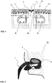
- the structural joint bridging device 10 shown serves to bridge or seal a joint F located between two structural parts.
- the structural joint bridging device 10 has a joint sealing profile 1 extending over the joint F.
- the joint sealing profile 1 for its part has a left holding area 2 and a right holding area 3.
- the left holding area 2 is inserted into a left carrier 11 of the building joint bridging device 10 and correspondingly the right holding area 3 is inserted into a right carrier 12 of the building joint bridging device 10.
- the left support 11 and the right support 12 are each firmly connected to the associated left component 13 and the right component 14.
- the building joint bridging device 10 in the embodiment shown has an anchor structure K on each side of the joint F, via which the respective carrier is anchored to the building.
- FIG. 11 shows an enlarged portion of FIG Fig. 1 building joint bridging device 10 shown, namely the right holding area 3 of the joint sealing profile 1 as it is in engagement with the right support 12 of the building joint bridging device 10.
- the holding area has a composition of matter 4 which is in an activated state.
- the composition of matter is designed in such a way that its volume and thus also the volume of the right holding area 3 increases after activation.
- the right holding area 3 hugs the inner wall of the recess A of the right support 12 almost over its entire surface.
- the substance composition is dosed in such a way that the holding area 3 would expand significantly beyond the volume available in the recess A in a non-built-in situation after activation.
- Fig. 3 is the same sub-area of the structural joint bridging device as in Fig. 2 shown, but here the composition of matter 4 is in a non-activated state. So this is the situation when introducing the profile in the recess A of the carrier 12 or when Remove. It can be seen that the right holding area 3, in contrast to the activated state, has a smaller cross section, which means that the holding area can easily be inserted into or removed from the opening of the recess. When inserting or removing the holding area 3 into the recess A, the holding area only has to be deformed slightly or, if necessary, not at all. After activation, however, the holding area 3 is held in the recess A in both a frictional and form-locking manner in the recess A, since after the holding area has been activated, it produces a claw-like undercut.
- the shown second embodiment of the joint sealing profile according to the invention has a left holding area 2 and a right holding area 3, with a shape that is adapted to the shape of the recess in the carrier, see FIG Figures 1 to 3 .
- the activatable composition of matter 4 is also arranged in the holding areas 2 and 3.
- the figure shown is the shape of the holding area after activation of the composition 4 on the right holding area 3 indicated by dashed lines.
- the composition of matter 4 on the left holding area 3 is shown in the non-activated state.
Landscapes
- Engineering & Computer Science (AREA)
- Architecture (AREA)
- Civil Engineering (AREA)
- Structural Engineering (AREA)
- Physics & Mathematics (AREA)
- Electromagnetism (AREA)
- Sealing Material Composition (AREA)
- Road Paving Structures (AREA)
- Building Environments (AREA)
- Gasket Seals (AREA)
- Bridges Or Land Bridges (AREA)
- Automobile Manufacture Line, Endless Track Vehicle, Trailer (AREA)
- Forging (AREA)
- Heating, Cooling, Or Curing Plastics Or The Like In General (AREA)
Claims (15)
- Dispositif de pontage (10) de joint de construction pour étanchéifier des transitions de voies de circulation de voitures ou de voies piétonnes dans des ponts, ledit dispositif de pontage (10) de joint de construction comportant au moins une poutre (11, 12) et au moins un profilé d'étanchéification (1) de joint de construction, ledit profilé d'étanchéification (1) consistant, au moins en partie, en un matériau élastique et comportant au moins une région de retenue (2, 3) pour la fixation sur le poutre (11, 12) dudit dispositif de pontage (10) de joint de construction, ladite poutre (11, 12) comportant un évidement (A) pour loger au moins une région de retenue (2, 3) dudit profilé d'étanchéification (1) de joint de construction,ledit évidement (A) comportant une contre-dépouille,au moins une région de retenue (2, 3) dudit profilé d'étanchéification (1) étant insérée dans ledit évidement (A),caractérisé en ce que ladite région de retenue (2, 3) ayant, au moins dans une partie, une composition de matière (4) qui peut être activée, de manière ciblée, par une application chimique, thermique et/ou physique de façon que le volume de ladite région de retenue (2, 3) est augmenté afin de créer entre ladite région de retenue (2, 3) et ledit évidement (A) une liaison à engagement positif et à adhérence.
- Dispositif de pontage (10) de joint de construction selon la revendication 1,
caractérisé en ce que
l'augmentation du volume est au moins en partie réversible. - Dispositif de pontage (10) de joint de construction selon l'une quelconque des revendications précédentes,
caractérisé en ce que
la composition de matière (4) comprend un matériau gonflable moyennant un liquide de façon que ladite application peut être effectué moyennant un tel liquide. - Dispositif de pontage (10) de joint de construction selon la revendication 3,
caractérisé en ce que
le matériau gonflable comprend un minéral ou un polymère gonflable dans l'eau. - Dispositif de pontage (10) de joint de construction selon la revendication 3 ou 4,
caractérisé en ce que
le matériau gonflable comprend un granulé comportant un matériau superabsorbant sur la base d'un polymère d'acide acrylique et un matériau de substrat élastomère. - Dispositif de pontage (10) de joint de construction selon l'une quelconque des revendications précédentes,
caractérisé en ce que
la composition de matière (4) comprend un matériau qui par l'application d'un agent chimique augmente en volume. - Dispositif de pontage (10) de joint de construction selon la revendication 3,
caractérisé en ce que
la composition de matière (4) comprend un prépolymère de sorte que ladite application peut être effectué par de l'eau, le prépolymère étant adapté pour libérer du CO2 en fonction du gonflage. - Dispositif de pontage (10) de joint de construction selon l'une quelconque des revendications précédentes,
caractérisé en ce que
la composition de matière (4) comprend un matériau comportant une affinité pour un champ de sorte que ladite application peut être effectué en appliquant un champ. - Dispositif de pontage (10) de joint de construction selon l'une quelconque des revendications précédentes,
caractérisé en ce que
ladite région de retenue (4) est adaptée de façon qu'elle est, lorsque qu'elle reçoit une application chimique, thermique et/ou physique, destinée à réaliser un contact contigu avec ledit évidement (A). - Utilisation d'un profilé d'étanchéification (1) de joint de construction comportant toutes les caractéristiques de la revendication 1 qui se réfèrent à un tel profilé d'étanchéification (1) dans un dispositif de pontage (10) de joint de construction selon l'une quelconque des revendications précédentes.
- Procédé pour la production d'un dispositif de pontage (10) de joint de construction selon l'une quelconque des revendications précédentes 1 à 9,
caractérisé en ce que
le profilé d'étanchéification (1) de joint de construction est fabriqué sous forme de profilé et la composition de matière (4) est introduit dans ledit profilé dans la région de retenue (2, 3). - Procédé selon la revendication 11,
caractérisé en ce que
on fabrique au moins une partie de la région de retenue (2, 3) qui comporte la composition de matière (4) sous forme d'un composant distinct et on unit celui-ci avec le profilé dans une étape distincte. - Procédé selon la revendication 12,
caractérisé en ce que
le composant distinct est fixé sur le profilé par vulcanisation. - Procédé selon l'une quelconque des revendications 11 à 13,
caractérisé en ce que
on insère le profilé d'étanchéification (1) de joint de construction dans l'évidement (A) et on effectue une application chimique, thermique et/ou physique sur la région de retenue de façon que le volume celle-ci est augmenté. - Procédé pour le démontage d'un dispositif de pontage (10) de joint de construction selon l'une quelconque des revendications 1 à 9,
caractérisé en ce que
on modifie l'application chimique, thermique et/ou physique sur la région de retenue (2, 3) du profilé d'étanchéification (1) de joint de construction en état monté dans l'évidement (A) de tel façon que le volume celle-ci est réduit.
Priority Applications (4)
| Application Number | Priority Date | Filing Date | Title |
|---|---|---|---|
| RS20220234A RS62994B1 (sr) | 2017-11-23 | 2018-11-21 | Uređaj za premošćenje građevinskih zazora i postupak za izradu uređaja za premošćenje građevinskih zazora |
| HRP20220398TT HRP20220398T1 (hr) | 2017-11-23 | 2018-11-21 | Uređaj za premošćivanje strukturnih spojeva i postupak proizvodnje uređaja za premošćivanje strukturnih spojeva |
| SI201830596T SI3701098T1 (sl) | 2017-11-23 | 2018-11-21 | Premostitvena naprava gradbenih spojev in postopek za izdelavo premostitvene naprave gradbenih spojev |
| PL18807948T PL3701098T3 (pl) | 2017-11-23 | 2018-11-21 | Urządzenie do mostkowania styków konstrukcyjnych i sposób wytwarzania urządzenia do mostkowania styków konstrukcyjnych |
Applications Claiming Priority (2)
| Application Number | Priority Date | Filing Date | Title |
|---|---|---|---|
| DE102017220915.1A DE102017220915A1 (de) | 2017-11-23 | 2017-11-23 | Fugendichtprofil, Bauwerksfugenüberbrückungsvorrichtung und Verfahren zum Herstellen eines Fugendichtprofils |
| PCT/EP2018/082106 WO2019101804A1 (fr) | 2017-11-23 | 2018-11-21 | Profil d'étanchéité de joints, dispositif de pontage de joints de construction et procédé destiné à la fabrication d'un profil d'étanchéité de joints |
Publications (2)
| Publication Number | Publication Date |
|---|---|
| EP3701098A1 EP3701098A1 (fr) | 2020-09-02 |
| EP3701098B1 true EP3701098B1 (fr) | 2021-12-29 |
Family
ID=64456979
Family Applications (1)
| Application Number | Title | Priority Date | Filing Date |
|---|---|---|---|
| EP18807948.7A Active EP3701098B1 (fr) | 2017-11-23 | 2018-11-21 | Dispositif de pontage de joints de construction et procédé destiné à la fabrication d'un dispositif de pontage de joints de construction |
Country Status (25)
| Country | Link |
|---|---|
| US (1) | US11384490B2 (fr) |
| EP (1) | EP3701098B1 (fr) |
| JP (1) | JP7133016B2 (fr) |
| KR (1) | KR20200096249A (fr) |
| CN (1) | CN111566290A (fr) |
| AU (1) | AU2018373772B2 (fr) |
| CA (1) | CA3083072C (fr) |
| CL (1) | CL2020001356A1 (fr) |
| DE (1) | DE102017220915A1 (fr) |
| DK (1) | DK3701098T3 (fr) |
| ES (1) | ES2906393T3 (fr) |
| HR (1) | HRP20220398T1 (fr) |
| HU (1) | HUE058000T2 (fr) |
| IL (1) | IL274805B2 (fr) |
| MX (1) | MX2020005269A (fr) |
| NZ (1) | NZ764970A (fr) |
| PH (1) | PH12020550682A1 (fr) |
| PL (1) | PL3701098T3 (fr) |
| PT (1) | PT3701098T (fr) |
| RS (1) | RS62994B1 (fr) |
| RU (1) | RU2748262C1 (fr) |
| SG (1) | SG11202004830VA (fr) |
| SI (1) | SI3701098T1 (fr) |
| UA (1) | UA125197C2 (fr) |
| WO (1) | WO2019101804A1 (fr) |
Families Citing this family (2)
| Publication number | Priority date | Publication date | Assignee | Title |
|---|---|---|---|---|
| AU2023219910A1 (en) * | 2023-08-24 | 2025-03-13 | Illinois Tool Works Inc. | Apparatus for forming a pathway joint |
| USD1106498S1 (en) | 2023-08-24 | 2025-12-16 | Illinois Tool Works Inc. | Joint former |
Family Cites Families (38)
| Publication number | Priority date | Publication date | Assignee | Title |
|---|---|---|---|---|
| US3598026A (en) * | 1969-01-31 | 1971-08-10 | Grace W R & Co | Joint-sealing apparatus |
| US3606826A (en) * | 1969-07-01 | 1971-09-21 | Acme Highway Prod | Expansion joint |
| CA1145131A (fr) * | 1980-04-05 | 1983-04-26 | Hajime Yamaji | Bouchure gonflant a l'eau, et methode d'obturation connexe |
| US4366284A (en) * | 1980-10-17 | 1982-12-28 | Hayakawa Rubber Company Limited | Aqueously-swelling water stopper and a process of stopping water thereby |
| DE3151516C2 (de) * | 1981-12-24 | 1985-04-18 | Migua Hammerschmidt GmbH, 5628 Heiligenhaus | Vorrichtung zur Überbrückung von Bewegungsfugen |
| JPS59222672A (ja) * | 1983-05-30 | 1984-12-14 | Masao Inuzuka | 通電膨張するシ−リング材 |
| US4622784A (en) * | 1984-12-18 | 1986-11-18 | Black David A | Pressurized waterstops |
| AU582901B2 (en) * | 1985-10-07 | 1987-04-09 | C.I. Kasei Co., Ltd. | A waterstop |
| GB2205872A (en) * | 1987-06-03 | 1988-12-21 | Grace W R Ltd | Waterstops with water-swellable edge regions |
| GB2208881A (en) | 1987-08-19 | 1989-04-19 | Grace W R Ltd | Waterstops for concrete with longitudinal and transverse ribs |
| US5071282A (en) * | 1988-11-17 | 1991-12-10 | The D. S. Brown Company, Inc. | Highway expansion joint strip seal |
| DE4104402C2 (de) * | 1991-02-14 | 1998-11-26 | Deflex Bautentechnik Gmbh | Dehnfugenkonstruktion |
| DE4114507C2 (de) * | 1991-05-03 | 1997-09-11 | Chemwell Chemie Gmbh | Schalldämmende Überbrückung von Dehnungsfugen |
| DE4422648C2 (de) * | 1994-06-28 | 1998-09-03 | Rene P Schmid | Sollriß-Fugenschiene |
| JPH09100544A (ja) * | 1995-10-09 | 1997-04-15 | Takeshige Shimonohara | プレキャストコンクリート部材の接合方法及び接合構造 |
| JP3018142B2 (ja) * | 1995-11-24 | 2000-03-13 | 三洋化成工業株式会社 | 止水工法用鋼矢板 |
| JP3693752B2 (ja) * | 1996-05-24 | 2005-09-07 | 株式会社ヤマックス | コンクリート製部材の接合方法並びに接合構造 |
| DE19800489A1 (de) * | 1998-01-09 | 1999-07-15 | Thomas Prof Dr Mang | Polysaccharidhaltige Dichtungszusammensetzung |
| GB9816365D0 (en) | 1998-07-28 | 1998-09-23 | Fosroc International Ltd | Waterstops and a method for their installation |
| JP2001247642A (ja) * | 1999-12-28 | 2001-09-11 | Asahi Denka Kogyo Kk | 水膨張性止水材 |
| CA2296230C (fr) * | 2000-01-18 | 2005-05-03 | Konrad Baerveldt | Joint d'etancheite hydrophile |
| RU15112U1 (ru) * | 2000-06-01 | 2000-09-20 | Закрытое акционерное общество "Триада-Холдинг" | Профильное уплотнение для герметизации деформационных швов (варианты) |
| JP4362209B2 (ja) * | 2000-06-02 | 2009-11-11 | 株式会社クリテック企画 | 道路橋伸縮継手 |
| JP2002180031A (ja) * | 2000-12-13 | 2002-06-26 | Asahi Denka Kogyo Kk | 水膨張性止水材およびその施工方法 |
| ATE490283T1 (de) * | 2001-09-04 | 2010-12-15 | W R Grace & Co A Connecticut Corp | Zweiphasenzusammensetzung aus superabsorbierendem und hydrophobem polymer |
| US6861477B2 (en) | 2001-12-21 | 2005-03-01 | Kimberly-Clark Worldwide, Inc. | Microphase separated superabsorbent compositions and method for making |
| BE1014719A3 (fr) | 2002-03-21 | 2004-03-02 | Travaux Galere S A Soc D | Joint de dilatation en aluminium coule a la resine. |
| JP2005350854A (ja) * | 2004-06-08 | 2005-12-22 | Kawaguchi Metal Industries Co Ltd | 橋梁用ジョイント |
| EP1614808A1 (fr) * | 2004-07-07 | 2006-01-11 | Mageba S.A. | Dispositif de recouvrement pour joint d'expansion |
| US7354219B2 (en) * | 2004-08-20 | 2008-04-08 | Leonberg Douglas E | Multi-seal waterproof expansion joint for roadways |
| KR100602217B1 (ko) | 2005-03-26 | 2006-07-19 | 보국산업(주) | 교량용 신축이음장치 |
| KR200438688Y1 (ko) | 2007-02-07 | 2008-02-29 | (주)트리탄코리아 | 신축이음장치용 실링재 |
| DE202009011357U1 (de) * | 2009-08-21 | 2011-01-13 | Pfeifer Holding Gmbh & Co. Kg | Dichtung für das Abdichten eines Vergusshohlraumes zwischen wenigstens zwei Bauteilen |
| DE102012023129B3 (de) * | 2012-11-27 | 2013-12-12 | Mageba S.A. | Dehnfugen-Überbrückungsvorrichtung |
| RU129119U1 (ru) * | 2013-02-12 | 2013-06-20 | Федеральное государственное бюджетное образовательное учреждение высшего профессионального образования "Петербургский государственный университет путей сообщения" | Устройство комплексной герметизации деформационных швов в железобетонных плитах |
| KR101372749B1 (ko) * | 2013-07-15 | 2014-03-11 | (주)대한콜크 | 복합 구조의 다성능 기능 지수판 |
| ES2621884T3 (es) * | 2013-10-24 | 2017-07-05 | Gcp Applied Technologies Inc. | Juntas de impermeabilización hinchables anti-serpenteo |
| RU152700U1 (ru) * | 2014-10-22 | 2015-06-10 | Общество с ограниченной ответственностью "НПП СК МОСТ" | Устройство для перекрытия деформационного шва |
-
2017
- 2017-11-23 DE DE102017220915.1A patent/DE102017220915A1/de not_active Withdrawn
-
2018
- 2018-11-21 RU RU2020120551A patent/RU2748262C1/ru active
- 2018-11-21 WO PCT/EP2018/082106 patent/WO2019101804A1/fr not_active Ceased
- 2018-11-21 UA UAA202003775A patent/UA125197C2/uk unknown
- 2018-11-21 HR HRP20220398TT patent/HRP20220398T1/hr unknown
- 2018-11-21 CA CA3083072A patent/CA3083072C/fr active Active
- 2018-11-21 PL PL18807948T patent/PL3701098T3/pl unknown
- 2018-11-21 HU HUE18807948A patent/HUE058000T2/hu unknown
- 2018-11-21 PT PT188079487T patent/PT3701098T/pt unknown
- 2018-11-21 ES ES18807948T patent/ES2906393T3/es active Active
- 2018-11-21 AU AU2018373772A patent/AU2018373772B2/en active Active
- 2018-11-21 RS RS20220234A patent/RS62994B1/sr unknown
- 2018-11-21 NZ NZ764970A patent/NZ764970A/en unknown
- 2018-11-21 JP JP2020528126A patent/JP7133016B2/ja active Active
- 2018-11-21 EP EP18807948.7A patent/EP3701098B1/fr active Active
- 2018-11-21 KR KR1020207018019A patent/KR20200096249A/ko not_active Ceased
- 2018-11-21 DK DK18807948.7T patent/DK3701098T3/da active
- 2018-11-21 IL IL274805A patent/IL274805B2/en unknown
- 2018-11-21 SG SG11202004830VA patent/SG11202004830VA/en unknown
- 2018-11-21 SI SI201830596T patent/SI3701098T1/sl unknown
- 2018-11-21 US US16/765,965 patent/US11384490B2/en active Active
- 2018-11-21 CN CN201880083552.XA patent/CN111566290A/zh active Pending
- 2018-11-21 MX MX2020005269A patent/MX2020005269A/es unknown
-
2020
- 2020-05-20 PH PH12020550682A patent/PH12020550682A1/en unknown
- 2020-05-22 CL CL2020001356A patent/CL2020001356A1/es unknown
Also Published As
| Publication number | Publication date |
|---|---|
| SG11202004830VA (en) | 2020-06-29 |
| SI3701098T1 (sl) | 2022-04-29 |
| PL3701098T3 (pl) | 2022-03-21 |
| RS62994B1 (sr) | 2022-03-31 |
| EP3701098A1 (fr) | 2020-09-02 |
| AU2018373772B2 (en) | 2022-02-17 |
| HRP20220398T1 (hr) | 2022-05-13 |
| CL2020001356A1 (es) | 2020-08-28 |
| IL274805B2 (en) | 2024-06-01 |
| CA3083072A1 (fr) | 2019-05-31 |
| KR20200096249A (ko) | 2020-08-11 |
| UA125197C2 (uk) | 2022-01-26 |
| US11384490B2 (en) | 2022-07-12 |
| PH12020550682A1 (en) | 2021-03-15 |
| DE102017220915A1 (de) | 2019-05-23 |
| NZ764970A (en) | 2022-10-28 |
| RU2748262C1 (ru) | 2021-05-21 |
| PT3701098T (pt) | 2022-03-16 |
| CA3083072C (fr) | 2023-08-01 |
| WO2019101804A1 (fr) | 2019-05-31 |
| JP7133016B2 (ja) | 2022-09-07 |
| ES2906393T3 (es) | 2022-04-18 |
| IL274805A (en) | 2020-07-30 |
| IL274805B1 (en) | 2024-02-01 |
| HUE058000T2 (hu) | 2022-06-28 |
| JP2021512969A (ja) | 2021-05-20 |
| MX2020005269A (es) | 2020-10-07 |
| US20200362523A1 (en) | 2020-11-19 |
| DK3701098T3 (da) | 2022-03-28 |
| AU2018373772A1 (en) | 2020-06-18 |
| CN111566290A (zh) | 2020-08-21 |
Similar Documents
| Publication | Publication Date | Title |
|---|---|---|
| DE19501384C9 (de) | Dichtungsvorrichtung zum Abdichten von Betonierfugen | |
| DE202017102967U1 (de) | Mobile Betonsperre | |
| DE19602245C2 (de) | Karosserieteil mit anextrudierter Dichtung | |
| LU82964A1 (de) | Verfahren zum schuetzen der oberflaechen von betonbauwerken und abdichtungselement zum durchfuehren dieses verfahrens | |
| EP2467541B1 (fr) | Joint pour fermeture étanche d'une cavité de coulée entre au moins deux éléments structuraux | |
| DE202009018645U1 (de) | Stopfen zum Verschluss von Öffnungen in Betonwänden | |
| EP3701098A1 (fr) | Profil d'étanchéité de joints, dispositif de pontage de joints de construction et procédé destiné à la fabrication d'un profil d'étanchéité de joints | |
| DE2650944A1 (de) | Zusammengesetzter profilstab fuer fenster- und fassadenkonstruktionen | |
| DE102013100242A1 (de) | Dichtungsprofil für ein Rahmenprofil und Rahmenprofil | |
| EP3757313A1 (fr) | Profilé de remplissage de joint | |
| DE202020004474U1 (de) | Lichtschacht mit Einrichtung zur Montage | |
| EP0358164B1 (fr) | Méthode pour installer une indication de fuite et/ou un espace d'isolation thermique entre une paroi et une plaque de revêtement de même que l'emploi de plaque de revêtement | |
| DE102010040663A1 (de) | Verbindungselement | |
| EP3228526B1 (fr) | Procede d'etancheification d'un bord de jonction | |
| DE102011002781A1 (de) | Bewehrungsanordnung und Schalungsanordnung | |
| DE19649476C2 (de) | Verfahren und Fugendichtung zum nachträglichen Abdichten von Bauwerksfugen zwischen Betonbauteilen | |
| EP3336296B1 (fr) | Cale de vitrage ainsi que battant de fenêtre ou de porte comportant une telle cale | |
| DE102009010365A1 (de) | Verkehrsleitwand sowie Verfahren zum Errichten einer Verkehrsleitwand | |
| EP2354324B1 (fr) | Commutateur | |
| DE10310821B4 (de) | Vorrichtung zur Verbindung zweier Hohlprofile eines Rahmens zur Aufnahme von Lichtkuppelelementen | |
| DE10100713A1 (de) | Dichtmittel und Verfahren zum Verschließen einer Fuge | |
| DE2502731B1 (de) | Wasserdichte fugenuebergangskonstruktion fuer bruecken oder dergleichen bauwerke | |
| DE102012001647B4 (de) | Verfahren zur Versteifung eines Strukturbauteils eines Kraftfahrzeugs | |
| DE102023211382A1 (de) | Dichtung, Verfahren zur Montage einer Dichtung und Verfahren zur Herstellung einer Dichtung, insbesondere für ein Kraftfahrzeug | |
| DE3924054C2 (de) | Fensterrahmen, insbesondere aus Kunststoff und insbesondere für Kellerfenster |
Legal Events
| Date | Code | Title | Description |
|---|---|---|---|
| REG | Reference to a national code |
Ref country code: HR Ref legal event code: TUEP Ref document number: P20220398T Country of ref document: HR |
|
| STAA | Information on the status of an ep patent application or granted ep patent |
Free format text: STATUS: UNKNOWN |
|
| STAA | Information on the status of an ep patent application or granted ep patent |
Free format text: STATUS: THE INTERNATIONAL PUBLICATION HAS BEEN MADE |
|
| PUAI | Public reference made under article 153(3) epc to a published international application that has entered the european phase |
Free format text: ORIGINAL CODE: 0009012 |
|
| STAA | Information on the status of an ep patent application or granted ep patent |
Free format text: STATUS: REQUEST FOR EXAMINATION WAS MADE |
|
| 17P | Request for examination filed |
Effective date: 20200526 |
|
| AK | Designated contracting states |
Kind code of ref document: A1 Designated state(s): AL AT BE BG CH CY CZ DE DK EE ES FI FR GB GR HR HU IE IS IT LI LT LU LV MC MK MT NL NO PL PT RO RS SE SI SK SM TR |
|
| AX | Request for extension of the european patent |
Extension state: BA ME |
|
| DAV | Request for validation of the european patent (deleted) | ||
| DAX | Request for extension of the european patent (deleted) | ||
| GRAP | Despatch of communication of intention to grant a patent |
Free format text: ORIGINAL CODE: EPIDOSNIGR1 |
|
| STAA | Information on the status of an ep patent application or granted ep patent |
Free format text: STATUS: GRANT OF PATENT IS INTENDED |
|
| INTG | Intention to grant announced |
Effective date: 20210706 |
|
| GRAS | Grant fee paid |
Free format text: ORIGINAL CODE: EPIDOSNIGR3 |
|
| GRAA | (expected) grant |
Free format text: ORIGINAL CODE: 0009210 |
|
| STAA | Information on the status of an ep patent application or granted ep patent |
Free format text: STATUS: THE PATENT HAS BEEN GRANTED |
|
| AK | Designated contracting states |
Kind code of ref document: B1 Designated state(s): AL AT BE BG CH CY CZ DE DK EE ES FI FR GB GR HR HU IE IS IT LI LT LU LV MC MK MT NL NO PL PT RO RS SE SI SK SM TR |
|
| REG | Reference to a national code |
Ref country code: GB Ref legal event code: FG4D Free format text: NOT ENGLISH |
|
| REG | Reference to a national code |
Ref country code: CH Ref legal event code: EP |
|
| REG | Reference to a national code |
Ref country code: DE Ref legal event code: R096 Ref document number: 502018008364 Country of ref document: DE |
|
| REG | Reference to a national code |
Ref country code: AT Ref legal event code: REF Ref document number: 1458755 Country of ref document: AT Kind code of ref document: T Effective date: 20220115 |
|
| REG | Reference to a national code |
Ref country code: IE Ref legal event code: FG4D Free format text: LANGUAGE OF EP DOCUMENT: GERMAN |
|
| REG | Reference to a national code |
Ref country code: NL Ref legal event code: FP |
|
| REG | Reference to a national code |
Ref country code: PT Ref legal event code: SC4A Ref document number: 3701098 Country of ref document: PT Date of ref document: 20220316 Kind code of ref document: T Free format text: AVAILABILITY OF NATIONAL TRANSLATION Effective date: 20220309 |
|
| REG | Reference to a national code |
Ref country code: RO Ref legal event code: EPE |
|
| REG | Reference to a national code |
Ref country code: FI Ref legal event code: FGE |
|
| REG | Reference to a national code |
Ref country code: DK Ref legal event code: T3 Effective date: 20220324 |
|
| REG | Reference to a national code |
Ref country code: SE Ref legal event code: TRGR |
|
| REG | Reference to a national code |
Ref country code: LT Ref legal event code: MG9D |
|
| REG | Reference to a national code |
Ref country code: ES Ref legal event code: FG2A Ref document number: 2906393 Country of ref document: ES Kind code of ref document: T3 Effective date: 20220418 |
|
| PG25 | Lapsed in a contracting state [announced via postgrant information from national office to epo] |
Ref country code: LT Free format text: LAPSE BECAUSE OF FAILURE TO SUBMIT A TRANSLATION OF THE DESCRIPTION OR TO PAY THE FEE WITHIN THE PRESCRIBED TIME-LIMIT Effective date: 20211229 |
|
| REG | Reference to a national code |
Ref country code: HR Ref legal event code: T1PR Ref document number: P20220398 Country of ref document: HR |
|
| PG25 | Lapsed in a contracting state [announced via postgrant information from national office to epo] |
Ref country code: NO Free format text: LAPSE BECAUSE OF FAILURE TO SUBMIT A TRANSLATION OF THE DESCRIPTION OR TO PAY THE FEE WITHIN THE PRESCRIBED TIME-LIMIT Effective date: 20220329 Ref country code: LV Free format text: LAPSE BECAUSE OF FAILURE TO SUBMIT A TRANSLATION OF THE DESCRIPTION OR TO PAY THE FEE WITHIN THE PRESCRIBED TIME-LIMIT Effective date: 20211229 |
|
| REG | Reference to a national code |
Ref country code: GR Ref legal event code: EP Ref document number: 20220400690 Country of ref document: GR Effective date: 20220509 |
|
| REG | Reference to a national code |
Ref country code: HU Ref legal event code: AG4A Ref document number: E058000 Country of ref document: HU |
|
| PG25 | Lapsed in a contracting state [announced via postgrant information from national office to epo] |
Ref country code: SM Free format text: LAPSE BECAUSE OF FAILURE TO SUBMIT A TRANSLATION OF THE DESCRIPTION OR TO PAY THE FEE WITHIN THE PRESCRIBED TIME-LIMIT Effective date: 20211229 Ref country code: EE Free format text: LAPSE BECAUSE OF FAILURE TO SUBMIT A TRANSLATION OF THE DESCRIPTION OR TO PAY THE FEE WITHIN THE PRESCRIBED TIME-LIMIT Effective date: 20211229 |
|
| PG25 | Lapsed in a contracting state [announced via postgrant information from national office to epo] |
Ref country code: IS Free format text: LAPSE BECAUSE OF FAILURE TO SUBMIT A TRANSLATION OF THE DESCRIPTION OR TO PAY THE FEE WITHIN THE PRESCRIBED TIME-LIMIT Effective date: 20220429 |
|
| REG | Reference to a national code |
Ref country code: DE Ref legal event code: R097 Ref document number: 502018008364 Country of ref document: DE |
|
| PG25 | Lapsed in a contracting state [announced via postgrant information from national office to epo] |
Ref country code: AL Free format text: LAPSE BECAUSE OF FAILURE TO SUBMIT A TRANSLATION OF THE DESCRIPTION OR TO PAY THE FEE WITHIN THE PRESCRIBED TIME-LIMIT Effective date: 20211229 |
|
| PLBE | No opposition filed within time limit |
Free format text: ORIGINAL CODE: 0009261 |
|
| STAA | Information on the status of an ep patent application or granted ep patent |
Free format text: STATUS: NO OPPOSITION FILED WITHIN TIME LIMIT |
|
| 26N | No opposition filed |
Effective date: 20220930 |
|
| REG | Reference to a national code |
Ref country code: HR Ref legal event code: ODRP Ref document number: P20220398 Country of ref document: HR Payment date: 20221116 Year of fee payment: 5 |
|
| PG25 | Lapsed in a contracting state [announced via postgrant information from national office to epo] |
Ref country code: MC Free format text: LAPSE BECAUSE OF FAILURE TO SUBMIT A TRANSLATION OF THE DESCRIPTION OR TO PAY THE FEE WITHIN THE PRESCRIBED TIME-LIMIT Effective date: 20211229 |
|
| PG25 | Lapsed in a contracting state [announced via postgrant information from national office to epo] |
Ref country code: LU Free format text: LAPSE BECAUSE OF NON-PAYMENT OF DUE FEES Effective date: 20221121 |
|
| PG25 | Lapsed in a contracting state [announced via postgrant information from national office to epo] |
Ref country code: IE Free format text: LAPSE BECAUSE OF NON-PAYMENT OF DUE FEES Effective date: 20221121 |
|
| REG | Reference to a national code |
Ref country code: HR Ref legal event code: ODRP Ref document number: P20220398 Country of ref document: HR Payment date: 20231114 Year of fee payment: 6 |
|
| PG25 | Lapsed in a contracting state [announced via postgrant information from national office to epo] |
Ref country code: CY Free format text: LAPSE BECAUSE OF FAILURE TO SUBMIT A TRANSLATION OF THE DESCRIPTION OR TO PAY THE FEE WITHIN THE PRESCRIBED TIME-LIMIT Effective date: 20211229 |
|
| PG25 | Lapsed in a contracting state [announced via postgrant information from national office to epo] |
Ref country code: MK Free format text: LAPSE BECAUSE OF FAILURE TO SUBMIT A TRANSLATION OF THE DESCRIPTION OR TO PAY THE FEE WITHIN THE PRESCRIBED TIME-LIMIT Effective date: 20211229 |
|
| PG25 | Lapsed in a contracting state [announced via postgrant information from national office to epo] |
Ref country code: MT Free format text: LAPSE BECAUSE OF FAILURE TO SUBMIT A TRANSLATION OF THE DESCRIPTION OR TO PAY THE FEE WITHIN THE PRESCRIBED TIME-LIMIT Effective date: 20211229 |
|
| REG | Reference to a national code |
Ref country code: HR Ref legal event code: ODRP Ref document number: P20220398 Country of ref document: HR Payment date: 20241112 Year of fee payment: 7 |
|
| REG | Reference to a national code |
Ref country code: CH Ref legal event code: U11 Free format text: ST27 STATUS EVENT CODE: U-0-0-U10-U11 (AS PROVIDED BY THE NATIONAL OFFICE) Effective date: 20251201 |
|
| PGFP | Annual fee paid to national office [announced via postgrant information from national office to epo] |
Ref country code: PT Payment date: 20251106 Year of fee payment: 8 |
|
| PGFP | Annual fee paid to national office [announced via postgrant information from national office to epo] |
Ref country code: HU Payment date: 20251118 Year of fee payment: 8 |
|
| PGFP | Annual fee paid to national office [announced via postgrant information from national office to epo] |
Ref country code: NL Payment date: 20251119 Year of fee payment: 8 |
|
| REG | Reference to a national code |
Ref country code: HR Ref legal event code: ODRP Ref document number: P20220398 Country of ref document: HR Payment date: 20251114 Year of fee payment: 8 |
|
| PGFP | Annual fee paid to national office [announced via postgrant information from national office to epo] |
Ref country code: DE Payment date: 20251118 Year of fee payment: 8 |
|
| PGFP | Annual fee paid to national office [announced via postgrant information from national office to epo] |
Ref country code: GB Payment date: 20251120 Year of fee payment: 8 |
|
| PGFP | Annual fee paid to national office [announced via postgrant information from national office to epo] |
Ref country code: AT Payment date: 20251117 Year of fee payment: 8 |
|
| PGFP | Annual fee paid to national office [announced via postgrant information from national office to epo] |
Ref country code: IT Payment date: 20251128 Year of fee payment: 8 Ref country code: FI Payment date: 20251118 Year of fee payment: 8 Ref country code: DK Payment date: 20251119 Year of fee payment: 8 |
|
| PGFP | Annual fee paid to national office [announced via postgrant information from national office to epo] |
Ref country code: HR Payment date: 20251114 Year of fee payment: 8 Ref country code: FR Payment date: 20251120 Year of fee payment: 8 |
|
| PGFP | Annual fee paid to national office [announced via postgrant information from national office to epo] |
Ref country code: TR Payment date: 20251114 Year of fee payment: 8 Ref country code: GR Payment date: 20251117 Year of fee payment: 8 Ref country code: BE Payment date: 20251118 Year of fee payment: 8 |
|
| PGFP | Annual fee paid to national office [announced via postgrant information from national office to epo] |
Ref country code: SE Payment date: 20251119 Year of fee payment: 8 Ref country code: CH Payment date: 20251201 Year of fee payment: 8 |
|
| PGFP | Annual fee paid to national office [announced via postgrant information from national office to epo] |
Ref country code: CZ Payment date: 20251107 Year of fee payment: 8 |
|
| PGFP | Annual fee paid to national office [announced via postgrant information from national office to epo] |
Ref country code: BG Payment date: 20251114 Year of fee payment: 8 Ref country code: PL Payment date: 20251112 Year of fee payment: 8 |
|
| PGFP | Annual fee paid to national office [announced via postgrant information from national office to epo] |
Ref country code: SK Payment date: 20251110 Year of fee payment: 8 Ref country code: RO Payment date: 20251118 Year of fee payment: 8 |
|
| PGFP | Annual fee paid to national office [announced via postgrant information from national office to epo] |
Ref country code: RS Payment date: 20251107 Year of fee payment: 8 |
|
| PGFP | Annual fee paid to national office [announced via postgrant information from national office to epo] |
Ref country code: SI Payment date: 20251111 Year of fee payment: 8 Ref country code: ES Payment date: 20251216 Year of fee payment: 8 |