EP3701115B1 - System zum auslösen eines kernprobenahmezylinders und kernprobenehmer mit einem solchen system - Google Patents
System zum auslösen eines kernprobenahmezylinders und kernprobenehmer mit einem solchen system Download PDFInfo
- Publication number
- EP3701115B1 EP3701115B1 EP18803464.9A EP18803464A EP3701115B1 EP 3701115 B1 EP3701115 B1 EP 3701115B1 EP 18803464 A EP18803464 A EP 18803464A EP 3701115 B1 EP3701115 B1 EP 3701115B1
- Authority
- EP
- European Patent Office
- Prior art keywords
- release
- coring device
- altitude
- control circuit
- depth
- Prior art date
- Legal status (The legal status is an assumption and is not a legal conclusion. Google has not performed a legal analysis and makes no representation as to the accuracy of the status listed.)
- Active
Links
Images


Classifications
-
- E—FIXED CONSTRUCTIONS
- E21—EARTH OR ROCK DRILLING; MINING
- E21B—EARTH OR ROCK DRILLING; OBTAINING OIL, GAS, WATER, SOLUBLE OR MELTABLE MATERIALS OR A SLURRY OF MINERALS FROM WELLS
- E21B25/00—Apparatus for obtaining or removing undisturbed cores, e.g. core barrels or core extractors
- E21B25/18—Apparatus for obtaining or removing undisturbed cores, e.g. core barrels or core extractors the core receiver being specially adapted for operation under water
Definitions
- the invention relates to the field of coring for taking samples of sediments from the bottom of the sea or a lake.
- the invention relates more particularly to a system for dropping a coring tube and a corer comprising such a system.
- the figures 1a-1e illustrate the operation of such a release system.
- the corer essentially comprises a coring device 10 and a mechanical system 11 for releasing the coring device, the assembly being rigged on a cable 12 from a winch positioned on a vessel at the surface.
- the coring device 10 comprises a coring tube 100 loaded with a ballast 101.
- the mechanical system 11 comprises a cantilever movable arm 110 provided with a cable 111 at its distal end of predetermined length and at its proximal end, of a pivot box 113 mounted on the core barrel.
- the cable 111 is equipped with a weight 112 at its lower end.
- the arm is under tension under the effect of the weight 112.
- the object of the present invention is to overcome all or part of the aforementioned drawbacks.
- the object of the invention is in particular to propose an electronic release system that is reliable, safe and consumes little energy.
- the release is controlled, via the control circuit, by the altimeter, which is supplied with energy only after the coring device has reached an arming depth. This makes it possible to avoid any unexpected or premature release of the coring device.
- such a system has a small footprint (no cantilever arms).
- control circuit triggers the release of said coring device by supplying energy to the release module.
- control circuit supplies energy to the drop module as soon as the arming depth is detected and triggers the release of said coring device by sending a release order to the drop module when the coring device reaches the altitude of dropping.
- the system further comprises an acoustic transducer connected to said control circuit, said control circuit being configured to supply electrical energy to said acoustic transducer when the coring device reaches the cocking depth and then trigger the emission of a sound signal to the surface by said acoustic transducer.
- This sound signal informs the ship on the surface that the system is “armed”.
- control circuit is also configured to interrupt the emission of the sound signal when the coring device reaches the release altitude.
- the control circuit is configured to interrupt the emission of a sound signal and cut off power supply to the control module if necessary.
- the control circuit is configured to stop supplying energy to said altimeter.
- the system is disarmed after a certain time if there has been no release. This makes it possible to improve the safety of the operations of ascent and reboarding of the corer.
- the release system further comprises storage means for recording data relating to the depths and/or the altitudes measured.
- the invention also relates to a corer comprising a coring device for taking a soil core from the seabed and a system for dropping the coring device, the dropping system being as defined above.
- the coring device comprises a ballast-carrying frame, at least one ballast mounted on said ballast-carrying frame and a coring tube mounted under the ballast-carrying frame and in that the release system is attached to the ballast frame or to the ballast.
- a sound signal is emitted to the surface.
- the release system of the invention is intended to release a coring device.
- This coring device may consist of a weighted coring tube.
- a release system 2 comprises a release module 20 for releasing the coring device on command, a pressure sensor 21 for measuring the depth of the coring device relative to the surface of the sea, an altimeter 22 to measure the altitude of the coring device relative to the seabed, a power source 23 of electrical energy, all of these elements being connected to a control circuit 24 via wired connections. These wired links allow both to supply the elements of the system and to transmit the control or measurement data.
- the release module 20 comprises for example an electric motor capable of rotating a cam to open a hook in the upper part of the coring device.
- the coring device 10 essentially comprises a weighted coring tube.
- the power source 23 is composed of one or more batteries, for example rechargeable lithium ion batteries 5S1P VL 34570 PM SG.
- the power source 23 permanently supplies the control circuit 24 and the pressure sensor 21.
- the control circuit 24 is configured to receive the depth measured by the pressure sensor 21, to supply electrical energy to the altimeter 22 when the coring device reaches a so-called arming depth, then to receive the altitude measured by the altimeter and finally trigger the release of the coring device when the coring device reaches a so-called release altitude.
- the release of the coring device is triggered only when the release altitude is reached. This last can only be measured after powering up the altimeter, which occurs when the coring device reaches the cocked depth. This double detection (loading depth and release altitude) and this conditional supply of the altimeter makes it possible to avoid any premature release of the coring device.
- the arming depth is calculated beforehand so that the system arms at approximately 100 or 200 meters from the seabed. For example, if the depth at the level of the coring zone is 2000 m, the system is armed between 1700 and 1900m.
- the control circuit 24 and the pressure sensor are powered by the power source 23.
- the power source powers at least the control circuit, the altimeter and the drop module.
- the pressure sensor also continues to be powered by the power source after arming to continue the depth measurements with a view to storing them for surface analysis purposes.
- the drop module can be energized only when the drop altitude is sensed.
- the release triggering command then consists in supplying the release module.
- the release module is supplied with energy as soon as the arming depth is detected.
- the release of the coring device is then triggered when the release module receives a release order from the control circuit. This release command is issued by the control circuit when the release altitude is detected.
- the system of the invention further comprises an acoustic transducer 25 (shown in dotted lines on the figure 2 ) connected to the control circuit 24.
- the control circuit 24 is then configured to supply electrical energy to the acoustic transducer when the coring device reaches the cocking depth and then trigger the emission of an audible signal towards the surface.
- This sound signal informs the ship on the surface that the system is “armed”.
- This sound signal is emitted continuously or in the form of beeps. It may include one or more beeps a few seconds apart.
- the transmission of the sound signal is advantageously interrupted by the control circuit when the coring device reaches the release altitude. If the release altitude is not detected at the end of a predetermined period, for example 15 or 20 minutes, the control circuit interrupts the emission of the sound signal and disarms the system by cutting off the supply to the release module. .
- the control circuit instead of interrupting the sound signal on detection of the release altitude, interrupts the emission of a sound signal at the end of a predetermined duration, for example 5 or 10 seconds, sufficiently long enough to ensure that the operator on the surface receives the sound signal.
- the release altitude is preferably determined to take account of the delay between the transmission of the release command by the control circuit 24 and the actual release by the release module 20. Indeed, when the release module receives the release control, the latter's motor drives a release cam which releases the coring device. There may therefore be a delay of the order of 0.5s or 1s between the transmission of the release command and the actual release. This means that, if an effective release is desired at 50 meters from the bottom, the release altitude must be greater than 50 meters. This discrepancy between the release command and the actual release can have an influence on the accuracy of the coring location. Indeed, the corer in free fall moves under the effect of the swell in particular and a shift in the height of fall can then result in a shift of the layers of sediment recovered in the tube.
- the operator on the surface can cancel the release operation after arming by sending an acoustic order to the control circuit via the acoustic transducer. Upon receipt of this order cancellation, the control circuit cuts off the power supply to the drop module.
- the system also advantageously comprises storage means for recording data relating to the depths and/or the altitudes measured during the descent of the corer.
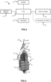
- FIG. 3 shows an example of a corer comprising a release system according to the invention.
- the corer comprises a coring device 3 essentially comprising a ballast-carrying frame 30, ballasts 31 arranged on the ballast-carrying frame and a coring tube 32 mounted at the lower end of the ballast-carrying frame 30.
- the release module 20 is mounted on the upper end of the ballast-carrying frame 30 and provides a mechanical connection between the rigging means of the boat and the corer.
- the rigging means 26 comprise a lifting cable 260 provided, at its lower end, with a thimble 261 and a mesh 262.
- the mesh 262 is attached to a strop 200 of the drop module 20.
- a coiled cable 27 loop is attached at one end to the thimble 261 and at the other end to a plunger inside the coring tube 32.
- the pressure sensor 21 and the altimeter 22 are fixed in the lower part of the ballast frame 200. In the example of the picture 3 , they are placed in the same box 28, which is fixed to the ballast frame 30.
- the control circuit 24 is an electronic card arranged inside a casing 29, which also contains the batteries forming the power source 23.
- This casing 29 is fixed to the ballast-carrying frame 30, above the ballasts 31.
- the acoustic transducer 25 is hooked to the ballast frame 30, next to the box 29.
- the box 29 is equipped with connectors to access the electronic card of the control circuit and the batteries.
- a computer can then be connected to the electronic card of the control circuit 24 to program, before launching the corer, the depth of armament and the drop altitude and, at the end of the mission after raising the corer on THE boat, recover the data recorded in the storage means of the electronic chart.
- the operation of such a corer is illustrated by the figures 4a- 4th.
- the corer descends towards the bottom as the cable 260 is unwound.
- the rate of descent of the corer is imposed by the winch unrolling the cable 260.
- the control circuit 24 triggers the energy supply to the altimeter 22 and to the acoustic transducer 25.
- the latter then emits a sound signal S.
- the operator on the surface can then decide to modify the unwinding speed of the cable 260 and in particular to reduce it to minimize the precision error due to the lag between the transmission of the release command and the actual release of the coring device.
- the corer continues its descent at the speed imposed by the lifting cable 260.
- the control circuit triggers, via the release module, the release of the coring device which then continues its descent in free fall.
- the control circuit 24 cuts the power supply to the acoustic transducer or sends it an order to stop the emission of the sound signal, in particular in order to save the batteries.
- the previously coiled cable 27 then unwinds as the coring device drops.
- the tip of the coring device reaches the bottom of the sea F, it sinks into the sediment under the effect of gravity ( 4d figure ).
- the assembly is then reassembled by means of cables 260 and 27 ( figure 4e ).
- the emission of the sound signal by the acoustic transducer 25 is interrupted when the corer reaches the release altitude or, if the latter is not reached, at the end of a predetermined period.
- a sound signal is transmitted to the surface at least during step E2.
- This transmission is interrupted at step E4, or, if the release altitude is not detected, at the end of a predetermined duration after the detection of the arming depth, to save the batteries of the system.
- control circuit is advantageously configured to stop supplying the altimeter with energy.
Landscapes
- Life Sciences & Earth Sciences (AREA)
- Engineering & Computer Science (AREA)
- Geology (AREA)
- Mining & Mineral Resources (AREA)
- Physics & Mathematics (AREA)
- Environmental & Geological Engineering (AREA)
- Fluid Mechanics (AREA)
- General Life Sciences & Earth Sciences (AREA)
- Geochemistry & Mineralogy (AREA)
- Geophysics And Detection Of Objects (AREA)
- Underground Or Underwater Handling Of Building Materials (AREA)
Claims (11)
- System (2) zum Abwerfen einer versenkten Kernbohrvorrichtung, die dazu bestimmt ist, einen Erdbohrkern aus dem Meeresboden zu entnehmen, das System umfassend:- ein Abwurfmodul (20) zum Abwerfen der Kernbohrvorrichtung auf Steuerung, wobei das Abwurfmodul (20) eine mechanische Verknüpfung zwischen dem Abwurfsystem (2) und einem Hubseil (260) eines Bootes sicherstellt,- einen Drucksensor (21) zum Messen der Tiefe der Kernbohrvorrichtung (30) relativ zu der Meeresoberfläche,- einen Höhenmesser (22) zum Messen der Höhe der Kernbohrvorrichtung (30) relativ zu dem Meeresboden,- eine Versorgungsquelle (23) für elektrische Energie, und- eine Steuerschaltung (24), die mit der Versorgungsquelle, dem Drucksensor, dem Höhenmesser und dem Abwurfmodul verbunden ist,dadurch gekennzeichnet, dass die Steuerschaltung konfiguriert ist zum• Erhalten der gemessenen Tiefe,• Versorgen des Höhenmessers (22) mit elektrischer Energie erst nachdem die Kernbohrvorrichtung (30) eine sogenannte Scharfmachtiefe erreicht hat, die so berechnet ist, dass sich das System in einem vorbestimmten Abstand von dem Meeresboden scharf macht,• Erhalten der gemessenen Höhe, und• Auslösen des Abwerfens der Kernbohrvorrichtung, wenn die Kernbohrvorrichtung (30) eine Abwurfhöhe erreicht.
- System nach Anspruch 1, dadurch gekennzeichnet, dass die Steuerschaltung (24) das Abwerfen der Kernbohrvorrichtung (30) auslöst, indem sie das Abwurfmodul (20) mit Energie versorgt.
- System nach Anspruch 1, dadurch gekennzeichnet, dass die Steuerschaltung (24) das Abwurfmodul (20) mit Energie versorgt, sobald die Scharfmachtiefe erfasst wird, und durch Senden eines Abwurfbefehls an das Abwurfmodul (20) das Abwerfen der Kernbohrvorrichtung (30) auslöst, wenn die Kernbohrvorrichtung die Abwurfhöhe erreicht.
- System nach einem der Ansprüche 1 bis 3, dadurch gekennzeichnet, dass es ferner einen akustischen Wandler (25) aufweist, der mit der Steuerschaltung (24) verbunden ist, wobei die Steuerschaltung (24) konfiguriert ist, um den akustischen Wandler (25) mit elektrischer Energie zu versorgen, wenn die Kernbohrvorrichtung (20) die Scharfmachtiefe erreicht, und dann die Ausgabe eines Tonsignals durch den akustischen Wandler auszulösen.
- System nach Anspruch 4, dadurch gekennzeichnet, dass die Steuerschaltung (24) ferner konfiguriert ist, um die Ausgabe des Tonsignals zu unterbrechen, wenn die Kernbohrvorrichtung die Abwurfhöhe erreicht.
- System nach Anspruch 4 oder 5, dadurch gekennzeichnet, dass, wenn die Abwurfhöhe für eine vorbestimmte Zeit nach der Erfassung der Scharfmachtiefe nicht erfasst wird, die Steuerschaltung (24) konfiguriert ist, um die Ausgabe des Tonsignals zu unterbrechen.
- System nach einem der Ansprüche 4 bis 6, dadurch gekennzeichnet, dass, wenn die Abwurfhöhe für eine vorbestimmte Zeit nach der Erfassung der Scharfmachtiefe nicht erfasst wird, die Steuerschaltung (24) konfiguriert ist, um die Energieversorgung des Höhenmessers zu stoppen.
- System nach einem der vorstehenden Ansprüche, dadurch gekennzeichnet, dass es ferner Speichermittel zum Aufzeichnen von Daten in Bezug auf die gemessenen Tiefen und/oder Höhen aufweist.
- Kernbohrer, der eine Kernbohrvorrichtung (3) zum Entnehmen eines Erdbohrkerns aus dem Meeresboden und ein Abwurfsystem (2) der Kernbohrvorrichtung aufweist, dadurch gekennzeichnet, dass das Abwurfsystem (2) einem der Ansprüche 1 bis 8 entspricht.
- Kernbohrer nach Anspruch 9, dadurch gekennzeichnet, dass die Kernbohrvorrichtung (3) einen Ballastträgerrahmen (30), mindestens einen Ballast (31), der an dem Ballastträgerrahmen (30) angebracht ist, und ein Kernbohrrohr (32) aufweist, das unter dem Ballastträgerrahmen (30) angebracht ist, und dadurch, dass das Abwurfsystem (30) an dem Ballastträgerrahmen (30) oder an dem Ballast (31) befestigt ist.
- Verfahren zum Steuern eines Abwurfmoduls (2), das dazu bestimmt ist, eine Kernbohrvorrichtung (3) abzuwerfen, wobei die Kernbohrvorrichtung dazu bestimmt ist, einen Erdbohrkern aus dem Meeresboden zu entnehmen, wobei das Verfahren dadurch gekennzeichnet ist, dass es die folgenden Schritte umfasst:- Messen (E1) der Tiefe der Kernbohrvorrichtung relativ zu der Meeresoberfläche und Erfassen einer sogenannten Scharfmachtiefe,- wenn die Scharfmachtiefe erfasst wird, Versorgen (E2) eines Höhenmessers mit elektrischer Energie,- Messen (E3), mit dem Höhenmesser, der Höhe der Kernbohrvorrichtung relativ zu dem Meeresboden und Erfassen einer Abwurfhöhe,- wenn die Abwurfhöhe erfasst wird, Auslösen (E4) des Abwerfens der Kernbohrvorrichtung (3) durch das Abwurfmodul.
Applications Claiming Priority (2)
| Application Number | Priority Date | Filing Date | Title |
|---|---|---|---|
| FR1760126A FR3072998B1 (fr) | 2017-10-27 | 2017-10-27 | Systeme de largage de tube de carrotage et carrottier comportant un tel systeme |
| PCT/FR2018/052677 WO2019081874A1 (fr) | 2017-10-27 | 2018-10-26 | Systeme de largage de tube de carrotage et carrottier comportant un tel systeme |
Publications (3)
| Publication Number | Publication Date |
|---|---|
| EP3701115A1 EP3701115A1 (de) | 2020-09-02 |
| EP3701115C0 EP3701115C0 (de) | 2023-06-07 |
| EP3701115B1 true EP3701115B1 (de) | 2023-06-07 |
Family
ID=62528471
Family Applications (1)
| Application Number | Title | Priority Date | Filing Date |
|---|---|---|---|
| EP18803464.9A Active EP3701115B1 (de) | 2017-10-27 | 2018-10-26 | System zum auslösen eines kernprobenahmezylinders und kernprobenehmer mit einem solchen system |
Country Status (3)
| Country | Link |
|---|---|
| EP (1) | EP3701115B1 (de) |
| FR (1) | FR3072998B1 (de) |
| WO (1) | WO2019081874A1 (de) |
Family Cites Families (4)
| Publication number | Priority date | Publication date | Assignee | Title |
|---|---|---|---|---|
| CN100507204C (zh) * | 2006-03-20 | 2009-07-01 | 国家海洋局第一海洋研究所 | 天然气水合物深水浅孔保温保压取芯钻具 |
| US8994527B2 (en) * | 2009-03-19 | 2015-03-31 | Galen G. Verhulst | Sea floor sampling device and method |
| AU2010333718A1 (en) * | 2009-12-17 | 2012-08-02 | Scope Engineering (Wa) Pty Ltd | Device for sampling cores from a seabed |
| CN107270897A (zh) * | 2017-06-21 | 2017-10-20 | 青岛东田智能科技有限公司 | 一种重力取样器工作状态测量记录仪 |
-
2017
- 2017-10-27 FR FR1760126A patent/FR3072998B1/fr not_active Expired - Fee Related
-
2018
- 2018-10-26 WO PCT/FR2018/052677 patent/WO2019081874A1/fr not_active Ceased
- 2018-10-26 EP EP18803464.9A patent/EP3701115B1/de active Active
Also Published As
| Publication number | Publication date |
|---|---|
| FR3072998A1 (fr) | 2019-05-03 |
| WO2019081874A1 (fr) | 2019-05-02 |
| EP3701115C0 (de) | 2023-06-07 |
| FR3072998B1 (fr) | 2020-09-11 |
| EP3701115A1 (de) | 2020-09-02 |
Similar Documents
| Publication | Publication Date | Title |
|---|---|---|
| EP2460728B1 (de) | Verfahren und Hilfsvorrichtung zur Lokalisierung eines Wracks eines Luftfahrzeugs in den Tiefen einer großen Meereswasserfläche | |
| EP2193070B1 (de) | Unterwasserboje | |
| EP2168871B1 (de) | Method for jettisoning an external load carried by an aircraft and its associated device | |
| FR3046988A1 (fr) | Systeme d'ejection de parachute pour aeronef | |
| EP0787095A1 (de) | Verfahren und vorrichtung zur vernichtung von unterwassergegenständen, insbesondere von seeminen | |
| FR2957680A1 (fr) | Balise ejectable et flottante, localisable avec precision ayant une autonomie energetique illimitee, stockant et emettant les donnees utiles ainsi que sa position courante et celle de l'aeronef | |
| CA2784188A1 (fr) | Engin marin ou sous-marin et procede d'arrimage associe | |
| FR3062369A1 (fr) | Systeme de securisation d'une balise immergee | |
| WO2016135326A1 (fr) | Poisson a portance hydrodynamique variable et ligne de remorquage comprenant le poisson | |
| EP3701115B1 (de) | System zum auslösen eines kernprobenahmezylinders und kernprobenehmer mit einem solchen system | |
| CA2960706A1 (fr) | Engin marin ou sous-marin et procede d'arrimage associe | |
| FR2943652A1 (fr) | Dispositif de manutention equipe d'un prehenseur de charge et de moyens de commande d'activation et de desactivation dudit prehenseur | |
| EP1205831B1 (de) | Verfahren zur Detektion vom Abflug eines Flugzeuges beim Starten | |
| EP2751012A1 (de) | Optisches system zur erfassung des wicklungszustands eines kabels an einer haspel | |
| FR2965543A1 (fr) | Systeme comprenant un engin sous-marin et une base situee en surface | |
| FR2943653A1 (fr) | Dispositif de manutention de charge equipe d'un capteur de mouvement | |
| FR3167374A1 (fr) | Système d’aide à la récupération d’au moins un objet immergé | |
| FR2529343A1 (fr) | Procede et dispositif de detection de nappes flottantes d'hydrocarbures ou de produits polluants analogues | |
| WO2021018738A1 (fr) | Procede de localisation d'un engin immerge derivant | |
| FR3051205A1 (fr) | Realisation de pieux avec un dispositif de forage a outil telescopable. | |
| FR3143773A1 (fr) | Unité de surveillance d’un sous-sol sous-marin et procédé associé | |
| EP1008830B1 (de) | Unterwasserschutzladung | |
| FR3096025A1 (fr) | Dispositif de mesure d'une ligne d'arbres, plateforme navale comportant un tel dispositif | |
| WO2025120100A1 (fr) | Titre : procédé de détermination de position d'ancre. | |
| FR2522226A1 (fr) | Procede et dispositif permettant d'etablir une liaison acoustique avec un appareil immerge |
Legal Events
| Date | Code | Title | Description |
|---|---|---|---|
| STAA | Information on the status of an ep patent application or granted ep patent |
Free format text: STATUS: UNKNOWN |
|
| STAA | Information on the status of an ep patent application or granted ep patent |
Free format text: STATUS: THE INTERNATIONAL PUBLICATION HAS BEEN MADE |
|
| PUAI | Public reference made under article 153(3) epc to a published international application that has entered the european phase |
Free format text: ORIGINAL CODE: 0009012 |
|
| STAA | Information on the status of an ep patent application or granted ep patent |
Free format text: STATUS: REQUEST FOR EXAMINATION WAS MADE |
|
| 17P | Request for examination filed |
Effective date: 20200428 |
|
| AK | Designated contracting states |
Kind code of ref document: A1 Designated state(s): AL AT BE BG CH CY CZ DE DK EE ES FI FR GB GR HR HU IE IS IT LI LT LU LV MC MK MT NL NO PL PT RO RS SE SI SK SM TR |
|
| AX | Request for extension of the european patent |
Extension state: BA ME |
|
| DAV | Request for validation of the european patent (deleted) | ||
| DAX | Request for extension of the european patent (deleted) | ||
| GRAP | Despatch of communication of intention to grant a patent |
Free format text: ORIGINAL CODE: EPIDOSNIGR1 |
|
| STAA | Information on the status of an ep patent application or granted ep patent |
Free format text: STATUS: GRANT OF PATENT IS INTENDED |
|
| INTG | Intention to grant announced |
Effective date: 20220830 |
|
| GRAS | Grant fee paid |
Free format text: ORIGINAL CODE: EPIDOSNIGR3 |
|
| GRAA | (expected) grant |
Free format text: ORIGINAL CODE: 0009210 |
|
| STAA | Information on the status of an ep patent application or granted ep patent |
Free format text: STATUS: THE PATENT HAS BEEN GRANTED |
|
| AK | Designated contracting states |
Kind code of ref document: B1 Designated state(s): AL AT BE BG CH CY CZ DE DK EE ES FI FR GB GR HR HU IE IS IT LI LT LU LV MC MK MT NL NO PL PT RO RS SE SI SK SM TR |
|
| REG | Reference to a national code |
Ref country code: GB Ref legal event code: FG4D Free format text: NOT ENGLISH |
|
| REG | Reference to a national code |
Ref country code: CH Ref legal event code: EP Ref country code: AT Ref legal event code: REF Ref document number: 1575657 Country of ref document: AT Kind code of ref document: T Effective date: 20230615 |
|
| REG | Reference to a national code |
Ref country code: DE Ref legal event code: R096 Ref document number: 602018051325 Country of ref document: DE |
|
| U01 | Request for unitary effect filed |
Effective date: 20230627 |
|
| U07 | Unitary effect registered |
Designated state(s): AT BE BG DE DK EE FI FR IT LT LU LV MT NL PT SE SI Effective date: 20230703 |
|
| REG | Reference to a national code |
Ref country code: LT Ref legal event code: MG9D |
|
| PG25 | Lapsed in a contracting state [announced via postgrant information from national office to epo] |
Ref country code: NO Free format text: LAPSE BECAUSE OF FAILURE TO SUBMIT A TRANSLATION OF THE DESCRIPTION OR TO PAY THE FEE WITHIN THE PRESCRIBED TIME-LIMIT Effective date: 20230907 Ref country code: ES Free format text: LAPSE BECAUSE OF FAILURE TO SUBMIT A TRANSLATION OF THE DESCRIPTION OR TO PAY THE FEE WITHIN THE PRESCRIBED TIME-LIMIT Effective date: 20230607 |
|
| U20 | Renewal fee for the european patent with unitary effect paid |
Year of fee payment: 6 Effective date: 20231018 |
|
| PG25 | Lapsed in a contracting state [announced via postgrant information from national office to epo] |
Ref country code: RS Free format text: LAPSE BECAUSE OF FAILURE TO SUBMIT A TRANSLATION OF THE DESCRIPTION OR TO PAY THE FEE WITHIN THE PRESCRIBED TIME-LIMIT Effective date: 20230607 Ref country code: HR Free format text: LAPSE BECAUSE OF FAILURE TO SUBMIT A TRANSLATION OF THE DESCRIPTION OR TO PAY THE FEE WITHIN THE PRESCRIBED TIME-LIMIT Effective date: 20230607 Ref country code: GR Free format text: LAPSE BECAUSE OF FAILURE TO SUBMIT A TRANSLATION OF THE DESCRIPTION OR TO PAY THE FEE WITHIN THE PRESCRIBED TIME-LIMIT Effective date: 20230908 |
|
| PG25 | Lapsed in a contracting state [announced via postgrant information from national office to epo] |
Ref country code: SK Free format text: LAPSE BECAUSE OF FAILURE TO SUBMIT A TRANSLATION OF THE DESCRIPTION OR TO PAY THE FEE WITHIN THE PRESCRIBED TIME-LIMIT Effective date: 20230607 |
|
| PG25 | Lapsed in a contracting state [announced via postgrant information from national office to epo] |
Ref country code: IS Free format text: LAPSE BECAUSE OF FAILURE TO SUBMIT A TRANSLATION OF THE DESCRIPTION OR TO PAY THE FEE WITHIN THE PRESCRIBED TIME-LIMIT Effective date: 20231007 |
|
| PG25 | Lapsed in a contracting state [announced via postgrant information from national office to epo] |
Ref country code: SM Free format text: LAPSE BECAUSE OF FAILURE TO SUBMIT A TRANSLATION OF THE DESCRIPTION OR TO PAY THE FEE WITHIN THE PRESCRIBED TIME-LIMIT Effective date: 20230607 Ref country code: SK Free format text: LAPSE BECAUSE OF FAILURE TO SUBMIT A TRANSLATION OF THE DESCRIPTION OR TO PAY THE FEE WITHIN THE PRESCRIBED TIME-LIMIT Effective date: 20230607 Ref country code: RO Free format text: LAPSE BECAUSE OF FAILURE TO SUBMIT A TRANSLATION OF THE DESCRIPTION OR TO PAY THE FEE WITHIN THE PRESCRIBED TIME-LIMIT Effective date: 20230607 Ref country code: IS Free format text: LAPSE BECAUSE OF FAILURE TO SUBMIT A TRANSLATION OF THE DESCRIPTION OR TO PAY THE FEE WITHIN THE PRESCRIBED TIME-LIMIT Effective date: 20231007 Ref country code: CZ Free format text: LAPSE BECAUSE OF FAILURE TO SUBMIT A TRANSLATION OF THE DESCRIPTION OR TO PAY THE FEE WITHIN THE PRESCRIBED TIME-LIMIT Effective date: 20230607 |
|
| PG25 | Lapsed in a contracting state [announced via postgrant information from national office to epo] |
Ref country code: PL Free format text: LAPSE BECAUSE OF FAILURE TO SUBMIT A TRANSLATION OF THE DESCRIPTION OR TO PAY THE FEE WITHIN THE PRESCRIBED TIME-LIMIT Effective date: 20230607 |
|
| REG | Reference to a national code |
Ref country code: DE Ref legal event code: R097 Ref document number: 602018051325 Country of ref document: DE |
|
| PLBE | No opposition filed within time limit |
Free format text: ORIGINAL CODE: 0009261 |
|
| STAA | Information on the status of an ep patent application or granted ep patent |
Free format text: STATUS: NO OPPOSITION FILED WITHIN TIME LIMIT |
|
| 26N | No opposition filed |
Effective date: 20240308 |
|
| PG25 | Lapsed in a contracting state [announced via postgrant information from national office to epo] |
Ref country code: MC Free format text: LAPSE BECAUSE OF FAILURE TO SUBMIT A TRANSLATION OF THE DESCRIPTION OR TO PAY THE FEE WITHIN THE PRESCRIBED TIME-LIMIT Effective date: 20230607 |
|
| REG | Reference to a national code |
Ref country code: CH Ref legal event code: PL |
|
| GBPC | Gb: european patent ceased through non-payment of renewal fee |
Effective date: 20231026 |
|
| PG25 | Lapsed in a contracting state [announced via postgrant information from national office to epo] |
Ref country code: GB Free format text: LAPSE BECAUSE OF NON-PAYMENT OF DUE FEES Effective date: 20231026 |
|
| PG25 | Lapsed in a contracting state [announced via postgrant information from national office to epo] |
Ref country code: CH Free format text: LAPSE BECAUSE OF NON-PAYMENT OF DUE FEES Effective date: 20231031 |
|
| PG25 | Lapsed in a contracting state [announced via postgrant information from national office to epo] |
Ref country code: GB Free format text: LAPSE BECAUSE OF NON-PAYMENT OF DUE FEES Effective date: 20231026 Ref country code: CH Free format text: LAPSE BECAUSE OF NON-PAYMENT OF DUE FEES Effective date: 20231031 |
|
| PG25 | Lapsed in a contracting state [announced via postgrant information from national office to epo] |
Ref country code: IE Free format text: LAPSE BECAUSE OF NON-PAYMENT OF DUE FEES Effective date: 20231026 |
|
| PG25 | Lapsed in a contracting state [announced via postgrant information from national office to epo] |
Ref country code: IE Free format text: LAPSE BECAUSE OF NON-PAYMENT OF DUE FEES Effective date: 20231026 |
|
| U21 | Renewal fee for the european patent with unitary effect paid with additional fee |
Year of fee payment: 7 Effective date: 20250327 |
|
| PG25 | Lapsed in a contracting state [announced via postgrant information from national office to epo] |
Ref country code: CY Free format text: LAPSE BECAUSE OF FAILURE TO SUBMIT A TRANSLATION OF THE DESCRIPTION OR TO PAY THE FEE WITHIN THE PRESCRIBED TIME-LIMIT; INVALID AB INITIO Effective date: 20181026 |
|
| PG25 | Lapsed in a contracting state [announced via postgrant information from national office to epo] |
Ref country code: HU Free format text: LAPSE BECAUSE OF FAILURE TO SUBMIT A TRANSLATION OF THE DESCRIPTION OR TO PAY THE FEE WITHIN THE PRESCRIBED TIME-LIMIT; INVALID AB INITIO Effective date: 20181026 |
|
| PG25 | Lapsed in a contracting state [announced via postgrant information from national office to epo] |
Ref country code: TR Free format text: LAPSE BECAUSE OF FAILURE TO SUBMIT A TRANSLATION OF THE DESCRIPTION OR TO PAY THE FEE WITHIN THE PRESCRIBED TIME-LIMIT Effective date: 20230607 |
|
| U1N | Appointed representative for the unitary patent procedure changed after the registration of the unitary effect |
Representative=s name: NOVAGRAAF TECHNOLOGIES; FR |