EP3701126B1 - Tunnelier et procédé de creusement de tunnel - Google Patents
Tunnelier et procédé de creusement de tunnel Download PDFInfo
- Publication number
- EP3701126B1 EP3701126B1 EP19730286.2A EP19730286A EP3701126B1 EP 3701126 B1 EP3701126 B1 EP 3701126B1 EP 19730286 A EP19730286 A EP 19730286A EP 3701126 B1 EP3701126 B1 EP 3701126B1
- Authority
- EP
- European Patent Office
- Prior art keywords
- excavation
- tool
- tunnelling
- boring machine
- tools
- Prior art date
- Legal status (The legal status is an assumption and is not a legal conclusion. Google has not performed a legal analysis and makes no representation as to the accuracy of the status listed.)
- Active
Links
Images



Classifications
-
- E—FIXED CONSTRUCTIONS
- E21—EARTH OR ROCK DRILLING; MINING
- E21D—SHAFTS; TUNNELS; GALLERIES; LARGE UNDERGROUND CHAMBERS
- E21D9/00—Tunnels or galleries, with or without linings; Methods or apparatus for making thereof; Layout of tunnels or galleries
- E21D9/10—Making by using boring or cutting machines
- E21D9/11—Making by using boring or cutting machines with a rotary drilling-head cutting simultaneously the whole cross-section, i.e. full-face machines
- E21D9/112—Making by using boring or cutting machines with a rotary drilling-head cutting simultaneously the whole cross-section, i.e. full-face machines by means of one single rotary head or of concentric rotary heads
-
- E—FIXED CONSTRUCTIONS
- E21—EARTH OR ROCK DRILLING; MINING
- E21D—SHAFTS; TUNNELS; GALLERIES; LARGE UNDERGROUND CHAMBERS
- E21D9/00—Tunnels or galleries, with or without linings; Methods or apparatus for making thereof; Layout of tunnels or galleries
- E21D9/003—Arrangement of measuring or indicating devices for use during driving of tunnels, e.g. for guiding machines
-
- E—FIXED CONSTRUCTIONS
- E21—EARTH OR ROCK DRILLING; MINING
- E21C—MINING OR QUARRYING
- E21C39/00—Devices for testing in situ the hardness or other properties of minerals, e.g. for giving information as to the selection of suitable mining tools
-
- E—FIXED CONSTRUCTIONS
- E21—EARTH OR ROCK DRILLING; MINING
- E21D—SHAFTS; TUNNELS; GALLERIES; LARGE UNDERGROUND CHAMBERS
- E21D9/00—Tunnels or galleries, with or without linings; Methods or apparatus for making thereof; Layout of tunnels or galleries
- E21D9/10—Making by using boring or cutting machines
- E21D9/108—Remote control specially adapted for machines for driving tunnels or galleries
Definitions
- the invention relates to a tunnel boring machine according to the preamble of claim 1.
- the invention further relates to a method for driving a tunnel.
- Such a tunnel boring machine is out DE 10 2011 114 830 B3 known.
- This tunnel boring machine has a rotatable cutting wheel and has a number of cutting tools equipped with cutting rollers which are arranged on the cutting wheel at specific cutting tool positions.
- sensor units there are a number of sensor units, one sensor unit being assigned to a respective mining tool and set up to record the state of the relevant mining tool in the form of associated mining tool data.
- a data processing device is provided, which is connected to the sensor units in order to display the rotational states of the cutting rollers on a screen.
- Out JPH10140981A is a method for detecting the wear of cutting rollers for excavation tools Tunnel boring machine known to achieve a relatively high operational reliability of the tunnel boring machine.
- the invention is based on the object of specifying a tunnel boring machine of the type mentioned at the outset and a method for driving a tunnel which, even with changing geology, is characterized by sufficiently reliable compliance with tool change intervals designed for maximum wear of excavation tools.
- mining tool data is recorded specifically for the mining tool and processed together with geodata on the tunneling section to be driven by means of a tunneling planning unit such that, with the tunneling parameters currently determined, tool change prognosis levels are either largely or preferably at least at a tool change prognosis level partially completely worn and therefore to be exchanged excavation tools or with only partially worn excavation tools that are still suitable after a change in the excavation tool position for reaching the next tool change prognosis level, relatively low operating costs result in relatively high reliability.
- FIG. 1 shows in a side view in a simplified representation an embodiment of a tunnel boring machine 103 according to the invention, which is equipped with a rotatable cutting wheel 106.
- a number of excavation tools 109 are attached to the cutting wheel 106, with each illustrated excavation tool 109 being equipped with a cutting roller 121 in this exemplary embodiment for excavating an advance section 112 in the existing geology 115 for the excavation of material on a working face 118 in the advance direction in front of the cutting wheel 106 is.
- Each mining tool 109 is assigned a sensor unit 124 which is set up to, by means of an in 1 non-illustrated temperature detection module to detect the temperature and/or the condition of the mining tool 109 in question, for example the state of wear and/or the state of rotation of the cutting roller 121 of the mining tool 109, in the form of associated mining tool data.
- the sensor units 124 protrude, for example, over a cable harness 127 and/or over a wireless signal link communicates with a mining tool measurement data storage 130 having a mining tool data storage area 133 for each sensor unit 124 .
- the current status and expediently also the status history for the associated mining tool 109 can be recorded over a specific period of time.
- the embodiment according to 1 formed with a speed sensor 136, with which a speed impressed on the cutting wheel 106 can be detected by a cutting wheel drive 139 via a cutting wheel gear 142.
- the speed sensor 136 is connected via a cable connection 145 and/or via a wireless signal path to a propulsion measurement data memory 148, with which the current speed and expediently also the speed history can be recorded over a specific period of time.
- a torque sensor 151 which is in operative connection with the cutting wheel drive 139 and with which the torque which is applied to the cutting wheel 106 can be detected.
- the torque transmitter 151 is connected via a further cable connection 154 and/or via a wireless signal path to the propulsion measurement data memory 148, with which the current torque and expediently also the torque history can be recorded over a specific period of time.
- the mining tool measurement data memory 130 and the propulsion measurement data memory 148 are available with an in 1 not shown, explained in more detail below data processing device wirelessly or wired in connection.
- pairs of driving presses 166 are also shown, which are held in a press bearing ring 169 and which, when driving a driving section 112, are supported on tubbings 172 provided for lining a tunnel. to press the cutting wheel 106 against the working face 118.
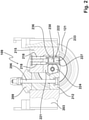
- FIG. 2 shows in a sectional view, by way of example, a removal tool 109 designed with a cutting roller 121 for a tunnel boring machine 103 according to the invention.
- the dismantling tool 109 is equipped with a cutting roller housing 203, by means of which, via an arrangement on both sides of the cutting roller 121, consists of a clamping wedge 212 that can be clamped using a clamping screw 206, which is supported on an abutment piece 209, and of a bearing block 215, which is connected by connecting screws 218 to a C -like designed clamping element 221, which is formed with a sensor housing 222, is connected, a cutting roller axis 224 is end-rotatably fixed.
- the sensor housing 222 accommodates an embodiment of a sensor unit 227 which is equipped in particular with a load sensor 230 and with a load transmitter 233 as components of a load detection module 236 .
- a load sensor 230 With the one that works, for example, by mechanically deforming a strain gauge or a strain gauge sleeve
- the mechanical load acting on the cutting roller axis 224 can be detected by the load sensor 230 .
- the data recorded by the load sensor 230 can be fed in via the load transmitter 233 to the removal tool measurement data memory 130 wirelessly or at least partially in a wired manner.
- the wear condition detection module 303 can be used, for example, to measure a distance to a cutting edge 306 of the cutting roller 121 as the highest area and thus characteristic of the degree of wear of the cutting roller 121 using a distance sensor 309 as a component of the wear condition detection module 303, the wear condition of the cutting roller 121 can be detected and via a distance transmitter 312 can be fed into the mining tool measurement data storage device 130 as a further component of the wear condition detection module 303 .
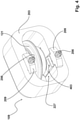
- FIG. 4 shows a perspective view by way of example of a removal tool 109 for a tunnel boring machine 103 according to the invention, which is equipped with a cutting roller 121, similar to the removal tools 109 explained above, and in which the sensor unit 227 is used in addition or as an alternative to a load detection module 236 and/or a wear condition detection module 303 is formed with a rotation status detection module 403 .
- the rotational status detection module 403 which operates contact-free in this embodiment, the rotational status of the cutting roller 121 can be detected and fed wirelessly or at least partially with a cable to the mining tool measurement data storage device 130 to determine whether the cutting roller 121 is rotating at all and, if so, at what speed.
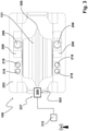
- FIG 5 shows a block diagram of an embodiment of a data processing device 503 for a tunnel boring machine 103 according to the invention, which is equipped with a tunnel boring machine 506.
- the extraction tool measurement data storage 130 and the advance measurement data storage 148 and on the other hand a geodata storage 512 are connected to a central tool management module 509 of the advance planning unit 506 .
- framework parameters for a current drive such as the diameter of the cutting wheel 106 and characteristic data for the mining tools 109 such as type, condition during installation and position after installation and on the other hand, in the form of so-called change logs, are read in from the mining tool measurement data memory 130 mining tool data provided with a time stamp can be stored.
- geodata memory 512 there are characteristic geodata for a tunneling section 112 to be excavated, which have been obtained, for example, through advance exploration via the geological analysis of drill cores and in particular include the type and sequence of the geology expected to be in front of the tunnel boring machine 103 in the tunneling direction.
- the tool management central module 509 is connected to a data processing module 515 and to a service life prediction module 518 as further components of the propulsion planning unit 506, with the data processing module 515 and the service life prediction module 518 also being connected to one another.
- an empirical value memory 521 in which empirical values from previous Drives in different geologies, including the geology expected for a current drive, can be stored
- a correction parameter memory 524 in which correction parameter values can be stored for use in a current drive
- the propulsion planning unit 506 is equipped with a comparison module 527, which is connected on the one hand to the service life prediction module 518 and on the other hand to a maintenance plan memory 530 of the propulsion planning unit 506, which is expediently also connected to the tool management central module 509 for updating at given times, such as in particular when tool change forecast levels are reached.
- the parallel arrangement of the change interval forecast module 536 and the running meter forecast module 539 is also connected to a change proposal processing module 542 of the propulsion planning unit 506, which is also connected to a demand comparison module 545 of the data processing device 503.
- the data processing device 503 essentially works as explained below.
- the data from the central tool management module 509, the empirical value memory 521 and the correction parameter memory 524 can be processed with the data processing module 515 in such a way that that with the service life prediction module 518 the comparison module 527 can be fed, very realistic target data as thus very reliable quasi-actual data on the basis of the current mining tool data and an assumed course of the future phases of the drive, the expected remaining service life of the mining tools 109 can be determined.
- the comparison module 527 can be used to compare the quasi-actual data according to realistic predetermination from the service life prediction module 518 with the target data assigned to the respective tunneling point according to interpolation predictions between tool change prediction levels from the maintenance plan memory 530 to the effect that, on the one hand, in the case of non-tolerable data, also explained in more detail below Corrective measures of propulsion parameters non-remediable deviations via the warning / alarm generator 533 an immediate alarm can be issued and on the other hand, in the case of deviations that are still tolerable in an automated self-learning mode, the correction parameter memory 524 can be fed correction data can be generated, with which via the correction parameter memory 524 and the data processing module 515 with the service life prediction module 518 Quasi-actual data can be generated, which lead to a smaller deviation of the quasi-actual data from the target data.
- the change interval forecast module 536 and the running meter forecast module 539 can be used to generate proposals for planning change intervals for changing positions to a new extraction tool position or exchanging extraction tools 109 for new extraction tools 109 at certain predicted running meters and feeding them into the change proposal processing module 542 , with which concrete instructions for work to be carried out at least for the next tool change prognosis level can be generated and displayed.
- the replacement interval prognosis module 536 can be used to generate suggested data such that advance parameters of the tunnel boring machine 103, such as the rotational speed of the cutting wheel 106 and/or the torque acting on the cutting wheel 106, are adapted in such a way that, in particular, even if the geology to be traveled through differs from the geodata conditions at least the next tool change prognosis level is preferably reached with excavation tools 109 that are optimally worn in the sense that at the next tool change prognosis level, excavation tools 109 are replaced due to complete wear and excavation tools 109 that are not yet completely worn are installed at new excavation tool positions in such a way that after such position changes only partially worn ones are installed Removal tools 109 reach at least the next but one tool change prognosis level until they are completely worn out.
- advance parameters of the tunnel boring machine 103 such as the rotational speed of the cutting wheel 106 and/or the torque acting on the cutting wheel 106
- the change proposal processing module 542 By connecting the change proposal processing module 542 to the requirements comparison module 545, the probable future requirement of mining tools 109 for tool change forecast levels can be estimated and, if the inventory of available new mining tools 109 for replacement with completely worn mining tools 109 falls below the warning/alarm generator 533, a warning message to increase of the inventory of new mining tools 109 up to the next tool change forecast level.
- the maintenance plan memory 530 When tool change prognosis levels are reached, it is expedient to update the maintenance plan memory 530 via the tool management central module 509 in such a way that after changing and/or exchanging removal tools 109, the maintenance plan memory 530 is informed of the then actual equipping of the Cutting wheel 106 can be stored with mining tools 109 in the respective state at the corresponding mining tool positions.
- 6 10 shows in a side view in a very simplified representation the exemplary embodiment of a tunnel boring machine 103 according to the invention 1 when excavating a tunneling section 112 below the surface of the earth in the existing geology 115 with changing conditions in the tunneling direction, symbolically represented by tunneling sections 603, 606, 609 filled with different symbols and with vertically aligned tool change prognosis levels 615, 618, 621, 624, 627 indicated by dashed lines , 630, as determined by the propulsion planning unit 506 at the status of the propulsion in the representation according to 6 have been predetermined.
- the tool change prognosis levels 615, 618, 621, 624, 627, 630 are spaced differently in hard tunneling sections 603, 606, 609 that differ in terms of geology, so that according to the invention, as explained in more detail above, the times for a change and/or replacement of excavation tools 109 can be scheduled relatively precisely. This significantly increases the cost-effectiveness of the drive compared to estimates based on empirical values.
Landscapes
- Engineering & Computer Science (AREA)
- Mining & Mineral Resources (AREA)
- Environmental & Geological Engineering (AREA)
- Life Sciences & Earth Sciences (AREA)
- General Life Sciences & Earth Sciences (AREA)
- Geochemistry & Mineralogy (AREA)
- Geology (AREA)
- Excavating Of Shafts Or Tunnels (AREA)
- Geophysics And Detection Of Objects (AREA)
- Earth Drilling (AREA)
Claims (15)
- Tunnelier avec une roue de coupe rotative (106), avec un certain nombre d'outils de taille (109), qui sont fixés à la roue de coupe (106) à certaines positions des outils de taille, avec un certain nombre d'unités de capteurs (124), une unité de capteurs (124) étant à chaque fois attribuée à un outil de coupe (109) et étant configurée pour enregistrer l'état de l'outil de taille (109) correspondant sous la forme de données d'outil de taille correspondant, et avec un dispositif de traitement de données (503) qui est en lien avec les unités de capteurs (124), caractérisé en ce que pour chaque unité de capteurs (124) il est prévu un domaine d'une unité de stockage de données des outils de taille (133) d'une unité de stockage de données de mesures des outils de taille (130), domaine dans lequel peuvent être enregistrées les données des outils de taille correspondantes à un outil de taille déterminé (109) issues d'une unité de capteurs (124) correspondante à l'outil de taille (109) associé, en ce que le dispositif de traitement des données (503) présente une unité de stockage des géo-données (512), dans laquelle des géo-données caractéristiques pour la géologie (115) à traverser pour l'itinéraire de creusement (112) à parcourir dans une direction de creusement peuvent être enregistrées, en ce que le dispositif de traitement des données (503) présente une unité de planification de creusement (506) avec un module central de gestion des outils (509), auquel sont reliées l'unité de stockage de données de mesures des outils de taille (130), une unité de stockage de données de mesures d'avancement de creusement (148) ainsi que l'unité de stockage des géo-données (512), et avec lequel des paramètres cadres pour un creusement actuel ainsi que des données caractéristiques pour les outils de tailles (109) sont enregistrables, tunnelier pour lequel avec l'unité de planification de creusement (506), sur la base des géo-données et des données des outils de taille, des paramètres de creusement ainsi que des positions des outils de taille (109) entre des plans prévisionnels de changement des outils (615, 618, 621, 624, 627, 630) situés dans la direction de creusement peuvent être déterminés de telle sorte qu'au niveau des plans prévisionnels de changement des outils (615, 618, 621, 624, 627, 630), pour des outils de taille (109) qui ne vont parvenir au plan prévisionnel de changement des outils (615, 618, 621, 624, 627, 630) suivant dans un état de fonctionnement satisfaisant que dans une autre position des outils de taille, il est procédé à un changement de position vers cette position des outils de taille ou une autre position des outils de taille, et pour des outils de taille (109) qui ne vont atteindre dans aucune position des outils de taille le plan prévisionnel de changement des outils (615, 618, 621, 624, 627, 630) suivant dans un état de fonctionnement satisfaisant, il est procédé à un échange contre un nouvel outil de taille (109) à installer.
- Tunnelier selon la revendication 1, caractérisé en ce qu'au niveau d'un plan prévisionnel de changement des outils (615, 618, 621, 624, 627, 630), les outils de taille (109) à changer sont complètement usés.
- Tunnelier selon la revendication 1 ou la revendication 2, caractérisé en ce qu'au moins une unité de capteurs (124) présente un module de détection de l'état d'usure (303), avec lequel l'état d'usure de l'outil de taille (109) correspondant à l'unité de capteurs (124) peut être détecté.
- Tunnelier selon l'une quelconque des revendications 1 à 3, caractérisé en ce qu'au moins une unité de capteurs (124) présente un module de détection de température, avec lequel la température de l'outil de taille (109) correspondant à l'unité de capteurs (124) peut être détectée.
- Tunnelier selon l'une des revendications 1 à 4, caractérisé en ce qu'au moins une unité de capteurs (124) présente un module de détection de charge (236), avec lequel la charge mécanique exercée sur l'outil de taille (109) correspondant à l'unité de capteurs (124) peut être détectée.
- Tunnelier selon l'une quelconque des revendications 1 à 5, caractérisé en ce qu'un certain nombre des outils de taille (109) sont formés avec des rouleaux de coupe (121) rotatifs.
- Tunnelier selon la revendication 6, caractérisé en ce qu'au moins une unité de capteurs (124) présente un module de détection de l'état de rotation (403), avec lequel l'état de rotation du rouleau de coupe (121) correspondant à l'unité de capteurs (124) peut être détecté.
- Tunnelier selon l'une quelconque des revendications 1 à 7, caractérisé en ce qu'il est prévu un capteur de vitesse de rotation (136), avec lequel la vitesse de rotation de la roue de coupe (106) peut être détectée, en ce que le capteur de vitesse de rotation (136) est relié avec le dispositif de traitement des données (503), en ce que la vitesse de rotation détectée peut être injectée dans l'unité de planification de creusement (506) et en ce que l'unité de planification de creusement (506) intègre la vitesse de rotation de la roue de coupe (106) pour la prédétermination d'un changement de position et/ou d'un échange des outils de taille (109).
- Tunnelier selon l'une quelconque des revendications 1 à 8, caractérisé en ce qu'il est prévu un capteur de couple (151) avec lequel le couple qui est appliqué à la roue de coupe (106) peut être détecté, en ce que le capteur de couple (151) est relié avec le dispositif de traitement des données (503), en ce que le couple détecté peut être injecté dans l'unité de planification de creusement (506) et en ce que l'unité de planification de creusement (506) intègre le couple de la roue de coupe (106) pour la prédétermination d'un changement de position et/ou d'un échange des outils de taille (109).
- Tunnelier selon l'une quelconque des revendications 1 à 9, caractérisé en ce que l'unité de planification de creusement (506) est équipée d'une unité de stockage de valeurs empiriques (521), dans laquelle des valeurs empiriques d'usure des outils de taille (109) lors de la conduite d'une trajectoire d'excavation (112) dans la géologie (115) peuvent être enregistrées, et en ce que l'unité de planification de creusement (506) intègre les valeurs empiriques pour la prédétermination d'un changement de position et/ou d'un échange des outils de taille (109).
- Tunnelier selon l'une quelconque des revendications 1 à 10, caractérisé en ce que l'unité de planification de creusement (506) est équipée d'un module de comparaison (527), avec lequel on peut comparer un état quasi réel selon la prédétermination proche de la réalité de l'état d'usure des outils de taille (109) avec l'état prévu selon la prévision d'interpolation entre des plans prévisionnels de changement des outils (615, 618, 621, 624, 627, 630), et en ce que l'unité de planification de creusement (506) présente une unité de stockage de corrections de paramètres (524), dans laquelle on peut enregistrer des paramètres de corrections déduits de la comparaison entre l'état quasi réel et l'état prévu, l'unité de planification de creusement (506) intégrant lesdits paramètres de corrections pour la prédétermination du changement de position et/ou du changement des outils de taille (109).
- Tunnelier selon l'une quelconque des revendications 1 à 11, caractérisé en ce que le dispositif de traitement des données (503) présente un générateur d'avertissement/d'alarme (533), qui est en relation avec l'unité de planification de creusement (506) et avec lequel des signaux d'avertissements et/ou des signaux d'alertes peuvent être délivrés lors d'états de fonctionnement et/ou d'états d'usure des outils de taille (109) critiques et/ou intolérables pour l'atteinte d'un plan prévisionnel de changement des outils (615, 618, 621, 624, 627, 630) selon la prévision d'interpolation entre des plans prévisionnels de changement des outils (615, 618, 621, 624, 627, 630).
- Tunnelier selon l'une quelconque des revendications 1 à 12, caractérisé en ce que le dispositif de traitement des données (503) est pourvu d'un module de comparaison des besoins (545), avec lequel peut être déterminé le besoin de remplacement par de nouveaux outils de taille (109) lors de l'atteinte d'au moins le plan prévisionnel de changement des outils (615, 618, 621, 624, 627, 630) suivant.
- Procédé pour le creusement d'un tunnel avec les étapes- mise à disposition d'un tunnelier (103) selon l'une quelconque des revendications 1 à 13,- mémorisation dans l'unité de stockage des géo-données (512) de géo-données caractéristiques pour la géologie (115) à traverser pour l'itinéraire de creusement (112) à parcourir dans une direction de creusement,- sur la base des géo-données et de données des outils de taille, détermination avec l'unité de planification de creusement (506) de paramètres de creusement et de positions des outils de taille (109) entre des plans prévisionnels de changement des outils (615, 618, 621, 624, 627, 630) situés dans la direction de creusement de telle sorte qu'au niveau des plans prévisionnels de changement des outils (615, 618, 621, 624, 627, 630), pour des outils de taille (109) qui ne vont parvenir au plan prévisionnel de changement des outils (615, 618, 621, 624, 627, 630) suivant dans un état de fonctionnement satisfaisant que dans une autre position des outils de taille, il est procédé à un changement de position vers cette position des outils de taille ou une autre position des outils de taille, et pour des outils de taille (109), qui ne vont atteindre dans aucune position des outils de taille le plan prévisionnel de changement des outils (615, 618, 621, 624, 627, 630) suivant dans un état de fonctionnement satisfaisant, il est procédé à un échange contre un nouvel outil de taille (109) à installer.
- Procédé selon la revendication 14, caractérisé en ce que les paramètres de creusement et les plans prévisionnels de changement des outils (615, 618, 621, 624, 627, 630) sont choisis de telle sorte qu'au niveau d'un plan prévisionnel de changement des outils (615, 618, 621, 624, 627, 630), les outils de taille (109) à changer sont complètement usés.
Applications Claiming Priority (2)
| Application Number | Priority Date | Filing Date | Title |
|---|---|---|---|
| DE102018113788.5A DE102018113788A1 (de) | 2018-06-08 | 2018-06-08 | Tunnelbohrmaschine |
| PCT/EP2019/064732 WO2019234131A1 (fr) | 2018-06-08 | 2019-06-05 | Tunnelier et procédé de creusement de tunnel |
Publications (2)
| Publication Number | Publication Date |
|---|---|
| EP3701126A1 EP3701126A1 (fr) | 2020-09-02 |
| EP3701126B1 true EP3701126B1 (fr) | 2022-02-09 |
Family
ID=66857869
Family Applications (1)
| Application Number | Title | Priority Date | Filing Date |
|---|---|---|---|
| EP19730286.2A Active EP3701126B1 (fr) | 2018-06-08 | 2019-06-05 | Tunnelier et procédé de creusement de tunnel |
Country Status (9)
| Country | Link |
|---|---|
| US (1) | US11668192B2 (fr) |
| EP (1) | EP3701126B1 (fr) |
| JP (1) | JP6949248B2 (fr) |
| CN (1) | CN112262251B (fr) |
| AU (1) | AU2019282289B2 (fr) |
| CA (1) | CA3101409A1 (fr) |
| DE (1) | DE102018113788A1 (fr) |
| ES (1) | ES2909346T3 (fr) |
| WO (1) | WO2019234131A1 (fr) |
Families Citing this family (8)
| Publication number | Priority date | Publication date | Assignee | Title |
|---|---|---|---|---|
| DE102019108002B4 (de) | 2019-03-28 | 2022-09-01 | Herrenknecht Aktiengesellschaft | Schneidrollenlagerteil, Schneidrollenhalterung mit Schneidrollenlagerteil, Schneidrad mit Schneidrollenhalterung und Tunnelvortriebsmaschine mit Schneidrad |
| CN111927558B (zh) * | 2020-10-13 | 2021-01-12 | 中国科学院武汉岩土力学研究所 | 动水软弱围岩隧道全断面掘进的安全预警方法及装置 |
| CN112065428B (zh) * | 2020-11-16 | 2021-01-15 | 中南大学 | 基于声波共振的非开挖导向钻头的声波定位系统及方法 |
| DE102020133386A1 (de) * | 2020-12-14 | 2022-06-15 | Herrenknecht Aktiengesellschaft | Vorrichtung und Verfahren zum Vortreiben eines Tunnels |
| DE102021110855A1 (de) | 2021-04-28 | 2022-11-03 | Herrenknecht Aktiengesellschaft | Schneidrad für eine Tunnelvortriebsmaschine |
| DE102022124534A1 (de) * | 2022-09-23 | 2024-03-28 | Herrenknecht Aktiengesellschaft | Tunnelbohrmaschine |
| US12037908B1 (en) * | 2023-05-17 | 2024-07-16 | China Tiesiju Civil Engineering Group Co., Ltd. | Method for monitoring and analyzing large tunnel machines based on automatic collection of big data |
| KR102732135B1 (ko) * | 2023-07-21 | 2024-11-25 | 김선도 | 건드릴링 가공 현장 데이터 수집 시스템 및 방법 |
Family Cites Families (21)
| Publication number | Priority date | Publication date | Assignee | Title |
|---|---|---|---|---|
| JPH0653696U (ja) * | 1992-12-18 | 1994-07-22 | 株式会社小松製作所 | シールド掘進機のカッタビット摩耗検知装置 |
| JP3828615B2 (ja) * | 1996-08-16 | 2006-10-04 | 株式会社フジタ | トンネル掘削機械のカッタの損耗診断方法 |
| JPH10140981A (ja) | 1996-09-12 | 1998-05-26 | Komatsu Ltd | ディスクカッタの摩耗検出方法および摩耗検出装置 |
| JP3919172B2 (ja) * | 2002-04-17 | 2007-05-23 | 株式会社スターロイ | ディスクローラーカッター及びディスクローラーカッターモニタリングシステム |
| DE102007005560B4 (de) * | 2007-01-24 | 2009-12-03 | Bernhard Sänger | Verfahren zum Betrieb einer Tunnelbohrmaschine, Verfahren zum Erkennen von geologischen Strukturen sowie Tunnelbohrmaschine |
| AU2009260436B2 (en) * | 2008-05-30 | 2013-01-24 | The Robbins Company | Apparatus and method for monitoring tunnel boring efficiency |
| US7832960B2 (en) * | 2008-12-17 | 2010-11-16 | The Robbins Company | All-conditions tunnel boring machine |
| CN101936169B (zh) * | 2010-08-24 | 2011-12-07 | 中铁隧道装备制造有限公司 | 软岩盾构机中具有小范围变径功能的切削装置 |
| CN101975563A (zh) * | 2010-09-14 | 2011-02-16 | 沈阳重型机械集团有限责任公司 | 盾构刮刀磨损检测装置 |
| DE102011114830B3 (de) * | 2011-10-05 | 2013-03-07 | Herrenknecht Ag | Vorrichtung zum Überwachen des Drehzustandes einer Schneidrollenanordnung einer Schildvortriebsmaschine und Schneidrollenanordnung für eine Schildvortriebsmaschine |
| EP2578797B1 (fr) | 2011-10-07 | 2017-05-03 | KEURO Besitz GmbH & Co. EDV-Dienstleistungs KG | Procédé de gestion de tiges de forage, outils de forage, colonnes de cuvelage pour trous de forage et analogues destinés à des puits de forage |
| US9297251B2 (en) * | 2013-02-20 | 2016-03-29 | Schlumberger Technology Corporation | Drill bit systems with temperature sensors and applications using temperature sensor measurements |
| DE102013112972A1 (de) * | 2013-11-25 | 2015-05-28 | Wirtgen Gmbh | Verschleißprognoseverfahren und Wartungsverfahren |
| JP6251128B2 (ja) * | 2014-06-13 | 2017-12-20 | 株式会社奥村組 | シールド掘進機による土質分布の判定方法 |
| CN104155300B (zh) * | 2014-08-19 | 2017-04-26 | 中交隧道工程局有限公司 | 一种盾构机刀具磨损的后部可视化检测装置及其方法 |
| WO2016141630A1 (fr) * | 2015-03-11 | 2016-09-15 | 山东大学 | Système de détection avancé sismique tridimensionnel combinant source active et source sismique d'abattage de roches pour tunnelier |
| CN105466327B (zh) * | 2015-12-31 | 2018-07-06 | 中国铁建重工集团有限公司 | 用于盾构机刀具磨损检测的传感器及装置、刀具系统 |
| JP6654504B2 (ja) * | 2016-05-17 | 2020-02-26 | 株式会社小松製作所 | トンネル掘進機 |
| JP2017210820A (ja) * | 2016-05-26 | 2017-11-30 | 五洋建設株式会社 | 回転ビットの状態を特定する装置および掘削機 |
| CN107545124B (zh) * | 2017-09-29 | 2019-11-12 | 天津大学 | 岩石隧道掘进机常截面盘形滚刀磨损状况的预测方法 |
| CN107882569A (zh) * | 2017-12-20 | 2018-04-06 | 江苏格睿特管网工程有限公司 | 一种可同时进行掘进与拼装的盾构机及施工工法 |
-
2018
- 2018-06-08 DE DE102018113788.5A patent/DE102018113788A1/de not_active Withdrawn
-
2019
- 2019-06-05 ES ES19730286T patent/ES2909346T3/es active Active
- 2019-06-05 EP EP19730286.2A patent/EP3701126B1/fr active Active
- 2019-06-05 AU AU2019282289A patent/AU2019282289B2/en active Active
- 2019-06-05 CN CN201980025613.1A patent/CN112262251B/zh active Active
- 2019-06-05 CA CA3101409A patent/CA3101409A1/fr active Pending
- 2019-06-05 JP JP2020556808A patent/JP6949248B2/ja active Active
- 2019-06-05 US US17/052,556 patent/US11668192B2/en active Active
- 2019-06-05 WO PCT/EP2019/064732 patent/WO2019234131A1/fr not_active Ceased
Also Published As
| Publication number | Publication date |
|---|---|
| CA3101409A1 (fr) | 2019-12-12 |
| JP2021521363A (ja) | 2021-08-26 |
| WO2019234131A1 (fr) | 2019-12-12 |
| EP3701126A1 (fr) | 2020-09-02 |
| DE102018113788A1 (de) | 2019-12-12 |
| ES2909346T3 (es) | 2022-05-06 |
| JP6949248B2 (ja) | 2021-10-13 |
| CN112262251A (zh) | 2021-01-22 |
| AU2019282289A1 (en) | 2020-11-26 |
| AU2019282289B2 (en) | 2024-07-18 |
| US20210180452A1 (en) | 2021-06-17 |
| CN112262251B (zh) | 2022-10-04 |
| US11668192B2 (en) | 2023-06-06 |
Similar Documents
| Publication | Publication Date | Title |
|---|---|---|
| EP3701126B1 (fr) | Tunnelier et procédé de creusement de tunnel | |
| EP2887049B1 (fr) | Procédé de pronostic d'usure pour une machine de travail de sols | |
| DE102015105908B4 (de) | Bohrgerät zum Erstellen einer verrohrten Bohrung und Verfahren zum Betreiben eines Bohrgerätes | |
| EP3296467B2 (fr) | Excavatrice et procédé associée | |
| EP3954831B1 (fr) | Machine de compactage du sol | |
| CN102110317B (zh) | 旋挖钻机施工存储系统 | |
| DE3100984A1 (de) | Verfahren zur ermittlung, ueberwachung und zum abbau der gebirgsschlaggefahr | |
| EP0203978B1 (fr) | Procede et systeme pour surveiller les foreuses a roues | |
| EP4051851A1 (fr) | Procédé assisté par ordinateur et système de détermination et de visualisation des flux de forces dans un échafaudage | |
| DE102007012678B3 (de) | Verfahren zum Steuern von Strebbetrieben im untertägigen Steinkohlenbergbau | |
| CH653406A5 (de) | Einrichtung zur herstellung zielgerichteter bohrungen. | |
| EP3978724B1 (fr) | Procédé de mise en uvre d'une opération de construction et dispositif de construction | |
| Quick et al. | Aicha‐Mauls on the Brenner Base Tunnel–status of the works and results | |
| DE3106156A1 (de) | Verfahren zur ueberwachung der streblage und geraet zur durchfuehrung des verfahrens | |
| WO2022117777A1 (fr) | Dispositif de fonçage pour le fonçage d'un puits dans le sol, ayant un dispositif pour déterminer la position du dispositif de fonçage dans le sol | |
| DE3126831C2 (de) | Verfahren zur Kontrolle der Geradhaltung der Schreitausbaufront und Vorrichtung zur Durchführung des Verfahrens | |
| EP4276559B1 (fr) | Procédé et système de détermination d'un état critique de fatigue de matériel dans une machine de travaux de génie civil | |
| JP2575051B2 (ja) | 泥水加圧シールド工法の施工管理方法 | |
| DE19750018C2 (de) | Meßeinrichtung für Vollschnittmaschinen im Hart-, Weich- und Lockergesteinsvortrieb zum Feststellen des Verschleißes der an Bohrkopf angeordneten Werkzeuge | |
| WO2003001032A2 (fr) | Procede permettant de determiner et d'evaluer des procedes d'abattage et dispositif correspondant | |
| Jordan et al. | Rescuing and rebuilding TBMs in adverse ground conditions | |
| Rehbock‐Sander et al. | Advance probing measures on the TBM drives of the south contracts of the Gotthard Base Tunnel–experience and implications for other projects/Vorauserkundungsmaßnahmen bei den TBM‐Vortrieben der Südlose des Gotthard‐Basistunnels–Erfahrungen und Folgerungen für andere Projekte | |
| DE2312078C3 (de) | Verfahren und Vorrichtung zur Überwachung der Vortriebsrichtung unterirdisch vorpressbarer Rohr- oder Tunnelschilde | |
| Handke | Application of the holistic observation method on shield tunnel drives as a means of preventing disputes and conflict reduction in case of interruptions/Anwendung der ganzheitlichen Beobachtungsmethode bei Schildvortrieben als Mittel zur präventiven Streitvermeidung und Konfliktreduzierung bei Störsituationen | |
| DE29624305U1 (de) | Vorrichtung zur Durchführung von Verfahren zum Bau von Tunnelanlagen |
Legal Events
| Date | Code | Title | Description |
|---|---|---|---|
| STAA | Information on the status of an ep patent application or granted ep patent |
Free format text: STATUS: UNKNOWN |
|
| STAA | Information on the status of an ep patent application or granted ep patent |
Free format text: STATUS: THE INTERNATIONAL PUBLICATION HAS BEEN MADE |
|
| PUAI | Public reference made under article 153(3) epc to a published international application that has entered the european phase |
Free format text: ORIGINAL CODE: 0009012 |
|
| STAA | Information on the status of an ep patent application or granted ep patent |
Free format text: STATUS: REQUEST FOR EXAMINATION WAS MADE |
|
| 17P | Request for examination filed |
Effective date: 20200529 |
|
| AK | Designated contracting states |
Kind code of ref document: A1 Designated state(s): AL AT BE BG CH CY CZ DE DK EE ES FI FR GB GR HR HU IE IS IT LI LT LU LV MC MK MT NL NO PL PT RO RS SE SI SK SM TR |
|
| AX | Request for extension of the european patent |
Extension state: BA ME |
|
| DAV | Request for validation of the european patent (deleted) | ||
| DAX | Request for extension of the european patent (deleted) | ||
| GRAP | Despatch of communication of intention to grant a patent |
Free format text: ORIGINAL CODE: EPIDOSNIGR1 |
|
| STAA | Information on the status of an ep patent application or granted ep patent |
Free format text: STATUS: GRANT OF PATENT IS INTENDED |
|
| INTG | Intention to grant announced |
Effective date: 20211020 |
|
| GRAS | Grant fee paid |
Free format text: ORIGINAL CODE: EPIDOSNIGR3 |
|
| GRAA | (expected) grant |
Free format text: ORIGINAL CODE: 0009210 |
|
| STAA | Information on the status of an ep patent application or granted ep patent |
Free format text: STATUS: THE PATENT HAS BEEN GRANTED |
|
| AK | Designated contracting states |
Kind code of ref document: B1 Designated state(s): AL AT BE BG CH CY CZ DE DK EE ES FI FR GB GR HR HU IE IS IT LI LT LU LV MC MK MT NL NO PL PT RO RS SE SI SK SM TR |
|
| REG | Reference to a national code |
Ref country code: GB Ref legal event code: FG4D Free format text: NOT ENGLISH |
|
| REG | Reference to a national code |
Ref country code: CH Ref legal event code: EP Ref country code: AT Ref legal event code: REF Ref document number: 1467626 Country of ref document: AT Kind code of ref document: T Effective date: 20220215 |
|
| REG | Reference to a national code |
Ref country code: DE Ref legal event code: R096 Ref document number: 502019003413 Country of ref document: DE |
|
| REG | Reference to a national code |
Ref country code: IE Ref legal event code: FG4D Free format text: LANGUAGE OF EP DOCUMENT: GERMAN |
|
| REG | Reference to a national code |
Ref country code: ES Ref legal event code: FG2A Ref document number: 2909346 Country of ref document: ES Kind code of ref document: T3 Effective date: 20220506 |
|
| REG | Reference to a national code |
Ref country code: LT Ref legal event code: MG9D |
|
| REG | Reference to a national code |
Ref country code: NL Ref legal event code: MP Effective date: 20220209 |
|
| PG25 | Lapsed in a contracting state [announced via postgrant information from national office to epo] |
Ref country code: SE Free format text: LAPSE BECAUSE OF FAILURE TO SUBMIT A TRANSLATION OF THE DESCRIPTION OR TO PAY THE FEE WITHIN THE PRESCRIBED TIME-LIMIT Effective date: 20220209 Ref country code: RS Free format text: LAPSE BECAUSE OF FAILURE TO SUBMIT A TRANSLATION OF THE DESCRIPTION OR TO PAY THE FEE WITHIN THE PRESCRIBED TIME-LIMIT Effective date: 20220209 Ref country code: PT Free format text: LAPSE BECAUSE OF FAILURE TO SUBMIT A TRANSLATION OF THE DESCRIPTION OR TO PAY THE FEE WITHIN THE PRESCRIBED TIME-LIMIT Effective date: 20220609 Ref country code: NO Free format text: LAPSE BECAUSE OF FAILURE TO SUBMIT A TRANSLATION OF THE DESCRIPTION OR TO PAY THE FEE WITHIN THE PRESCRIBED TIME-LIMIT Effective date: 20220509 Ref country code: NL Free format text: LAPSE BECAUSE OF FAILURE TO SUBMIT A TRANSLATION OF THE DESCRIPTION OR TO PAY THE FEE WITHIN THE PRESCRIBED TIME-LIMIT Effective date: 20220209 Ref country code: LT Free format text: LAPSE BECAUSE OF FAILURE TO SUBMIT A TRANSLATION OF THE DESCRIPTION OR TO PAY THE FEE WITHIN THE PRESCRIBED TIME-LIMIT Effective date: 20220209 Ref country code: HR Free format text: LAPSE BECAUSE OF FAILURE TO SUBMIT A TRANSLATION OF THE DESCRIPTION OR TO PAY THE FEE WITHIN THE PRESCRIBED TIME-LIMIT Effective date: 20220209 Ref country code: BG Free format text: LAPSE BECAUSE OF FAILURE TO SUBMIT A TRANSLATION OF THE DESCRIPTION OR TO PAY THE FEE WITHIN THE PRESCRIBED TIME-LIMIT Effective date: 20220509 |
|
| PG25 | Lapsed in a contracting state [announced via postgrant information from national office to epo] |
Ref country code: PL Free format text: LAPSE BECAUSE OF FAILURE TO SUBMIT A TRANSLATION OF THE DESCRIPTION OR TO PAY THE FEE WITHIN THE PRESCRIBED TIME-LIMIT Effective date: 20220209 Ref country code: LV Free format text: LAPSE BECAUSE OF FAILURE TO SUBMIT A TRANSLATION OF THE DESCRIPTION OR TO PAY THE FEE WITHIN THE PRESCRIBED TIME-LIMIT Effective date: 20220209 Ref country code: GR Free format text: LAPSE BECAUSE OF FAILURE TO SUBMIT A TRANSLATION OF THE DESCRIPTION OR TO PAY THE FEE WITHIN THE PRESCRIBED TIME-LIMIT Effective date: 20220510 Ref country code: FI Free format text: LAPSE BECAUSE OF FAILURE TO SUBMIT A TRANSLATION OF THE DESCRIPTION OR TO PAY THE FEE WITHIN THE PRESCRIBED TIME-LIMIT Effective date: 20220209 |
|
| PG25 | Lapsed in a contracting state [announced via postgrant information from national office to epo] |
Ref country code: IS Free format text: LAPSE BECAUSE OF FAILURE TO SUBMIT A TRANSLATION OF THE DESCRIPTION OR TO PAY THE FEE WITHIN THE PRESCRIBED TIME-LIMIT Effective date: 20220609 |
|
| PG25 | Lapsed in a contracting state [announced via postgrant information from national office to epo] |
Ref country code: SM Free format text: LAPSE BECAUSE OF FAILURE TO SUBMIT A TRANSLATION OF THE DESCRIPTION OR TO PAY THE FEE WITHIN THE PRESCRIBED TIME-LIMIT Effective date: 20220209 Ref country code: SK Free format text: LAPSE BECAUSE OF FAILURE TO SUBMIT A TRANSLATION OF THE DESCRIPTION OR TO PAY THE FEE WITHIN THE PRESCRIBED TIME-LIMIT Effective date: 20220209 Ref country code: RO Free format text: LAPSE BECAUSE OF FAILURE TO SUBMIT A TRANSLATION OF THE DESCRIPTION OR TO PAY THE FEE WITHIN THE PRESCRIBED TIME-LIMIT Effective date: 20220209 Ref country code: EE Free format text: LAPSE BECAUSE OF FAILURE TO SUBMIT A TRANSLATION OF THE DESCRIPTION OR TO PAY THE FEE WITHIN THE PRESCRIBED TIME-LIMIT Effective date: 20220209 Ref country code: DK Free format text: LAPSE BECAUSE OF FAILURE TO SUBMIT A TRANSLATION OF THE DESCRIPTION OR TO PAY THE FEE WITHIN THE PRESCRIBED TIME-LIMIT Effective date: 20220209 Ref country code: CZ Free format text: LAPSE BECAUSE OF FAILURE TO SUBMIT A TRANSLATION OF THE DESCRIPTION OR TO PAY THE FEE WITHIN THE PRESCRIBED TIME-LIMIT Effective date: 20220209 |
|
| REG | Reference to a national code |
Ref country code: DE Ref legal event code: R097 Ref document number: 502019003413 Country of ref document: DE |
|
| PG25 | Lapsed in a contracting state [announced via postgrant information from national office to epo] |
Ref country code: AL Free format text: LAPSE BECAUSE OF FAILURE TO SUBMIT A TRANSLATION OF THE DESCRIPTION OR TO PAY THE FEE WITHIN THE PRESCRIBED TIME-LIMIT Effective date: 20220209 |
|
| PLBE | No opposition filed within time limit |
Free format text: ORIGINAL CODE: 0009261 |
|
| STAA | Information on the status of an ep patent application or granted ep patent |
Free format text: STATUS: NO OPPOSITION FILED WITHIN TIME LIMIT |
|
| 26N | No opposition filed |
Effective date: 20221110 |
|
| PG25 | Lapsed in a contracting state [announced via postgrant information from national office to epo] |
Ref country code: MC Free format text: LAPSE BECAUSE OF FAILURE TO SUBMIT A TRANSLATION OF THE DESCRIPTION OR TO PAY THE FEE WITHIN THE PRESCRIBED TIME-LIMIT Effective date: 20220209 |
|
| REG | Reference to a national code |
Ref country code: BE Ref legal event code: MM Effective date: 20220630 |
|
| PG25 | Lapsed in a contracting state [announced via postgrant information from national office to epo] |
Ref country code: SI Free format text: LAPSE BECAUSE OF FAILURE TO SUBMIT A TRANSLATION OF THE DESCRIPTION OR TO PAY THE FEE WITHIN THE PRESCRIBED TIME-LIMIT Effective date: 20220209 |
|
| PG25 | Lapsed in a contracting state [announced via postgrant information from national office to epo] |
Ref country code: LU Free format text: LAPSE BECAUSE OF NON-PAYMENT OF DUE FEES Effective date: 20220605 Ref country code: IE Free format text: LAPSE BECAUSE OF NON-PAYMENT OF DUE FEES Effective date: 20220605 |
|
| PG25 | Lapsed in a contracting state [announced via postgrant information from national office to epo] |
Ref country code: BE Free format text: LAPSE BECAUSE OF NON-PAYMENT OF DUE FEES Effective date: 20220630 |
|
| PG25 | Lapsed in a contracting state [announced via postgrant information from national office to epo] |
Ref country code: MK Free format text: LAPSE BECAUSE OF FAILURE TO SUBMIT A TRANSLATION OF THE DESCRIPTION OR TO PAY THE FEE WITHIN THE PRESCRIBED TIME-LIMIT Effective date: 20220209 Ref country code: CY Free format text: LAPSE BECAUSE OF FAILURE TO SUBMIT A TRANSLATION OF THE DESCRIPTION OR TO PAY THE FEE WITHIN THE PRESCRIBED TIME-LIMIT Effective date: 20220209 |
|
| PG25 | Lapsed in a contracting state [announced via postgrant information from national office to epo] |
Ref country code: HU Free format text: LAPSE BECAUSE OF FAILURE TO SUBMIT A TRANSLATION OF THE DESCRIPTION OR TO PAY THE FEE WITHIN THE PRESCRIBED TIME-LIMIT; INVALID AB INITIO Effective date: 20190605 |
|
| PG25 | Lapsed in a contracting state [announced via postgrant information from national office to epo] |
Ref country code: MT Free format text: LAPSE BECAUSE OF FAILURE TO SUBMIT A TRANSLATION OF THE DESCRIPTION OR TO PAY THE FEE WITHIN THE PRESCRIBED TIME-LIMIT Effective date: 20220209 |
|
| PGFP | Annual fee paid to national office [announced via postgrant information from national office to epo] |
Ref country code: DE Payment date: 20250612 Year of fee payment: 7 |
|
| PGFP | Annual fee paid to national office [announced via postgrant information from national office to epo] |
Ref country code: GB Payment date: 20250620 Year of fee payment: 7 |
|
| PGFP | Annual fee paid to national office [announced via postgrant information from national office to epo] |
Ref country code: FR Payment date: 20250618 Year of fee payment: 7 |
|
| PGFP | Annual fee paid to national office [announced via postgrant information from national office to epo] |
Ref country code: AT Payment date: 20250616 Year of fee payment: 7 |
|
| PGFP | Annual fee paid to national office [announced via postgrant information from national office to epo] |
Ref country code: ES Payment date: 20250718 Year of fee payment: 7 |
|
| PGFP | Annual fee paid to national office [announced via postgrant information from national office to epo] |
Ref country code: IT Payment date: 20250630 Year of fee payment: 7 |
|
| PGFP | Annual fee paid to national office [announced via postgrant information from national office to epo] |
Ref country code: CH Payment date: 20250701 Year of fee payment: 7 |
|
| PG25 | Lapsed in a contracting state [announced via postgrant information from national office to epo] |
Ref country code: TR Free format text: LAPSE BECAUSE OF FAILURE TO SUBMIT A TRANSLATION OF THE DESCRIPTION OR TO PAY THE FEE WITHIN THE PRESCRIBED TIME-LIMIT Effective date: 20220209 |
|
| REG | Reference to a national code |
Ref country code: DE Ref legal event code: R082 Ref document number: 502019003413 Country of ref document: DE Representative=s name: MAUCHER JENKINS PATENTANWAELTE & RECHTSANWAELT, DE |