EP3701557B1 - Elektrisches sicherungselement sowie verfahren zum betreiben eines elektrischen sicherungselementes - Google Patents
Elektrisches sicherungselement sowie verfahren zum betreiben eines elektrischen sicherungselementes Download PDFInfo
- Publication number
- EP3701557B1 EP3701557B1 EP18779259.3A EP18779259A EP3701557B1 EP 3701557 B1 EP3701557 B1 EP 3701557B1 EP 18779259 A EP18779259 A EP 18779259A EP 3701557 B1 EP3701557 B1 EP 3701557B1
- Authority
- EP
- European Patent Office
- Prior art keywords
- fuse
- path
- load
- element according
- fuse element
- Prior art date
- Legal status (The legal status is an assumption and is not a legal conclusion. Google has not performed a legal analysis and makes no representation as to the accuracy of the status listed.)
- Active
Links
Images

Classifications
-
- H—ELECTRICITY
- H01—ELECTRIC ELEMENTS
- H01H—ELECTRIC SWITCHES; RELAYS; SELECTORS; EMERGENCY PROTECTIVE DEVICES
- H01H89/00—Combinations of two or more different basic types of electric switches, relays, selectors and emergency protective devices, not covered by any single one of the other main groups of this subclass
-
- H—ELECTRICITY
- H01—ELECTRIC ELEMENTS
- H01H—ELECTRIC SWITCHES; RELAYS; SELECTORS; EMERGENCY PROTECTIVE DEVICES
- H01H39/00—Switching devices actuated by an explosion produced within the device and initiated by an electric current
- H01H39/006—Opening by severing a conductor
-
- B—PERFORMING OPERATIONS; TRANSPORTING
- B60—VEHICLES IN GENERAL
- B60L—PROPULSION OF ELECTRICALLY-PROPELLED VEHICLES; SUPPLYING ELECTRIC POWER FOR AUXILIARY EQUIPMENT OF ELECTRICALLY-PROPELLED VEHICLES; ELECTRODYNAMIC BRAKE SYSTEMS FOR VEHICLES IN GENERAL; MAGNETIC SUSPENSION OR LEVITATION FOR VEHICLES; MONITORING OPERATING VARIABLES OF ELECTRICALLY-PROPELLED VEHICLES; ELECTRIC SAFETY DEVICES FOR ELECTRICALLY-PROPELLED VEHICLES
- B60L3/00—Electric devices on electrically-propelled vehicles for safety purposes; Monitoring operating variables, e.g. speed, deceleration or energy consumption
- B60L3/0007—Measures or means for preventing or attenuating collisions
-
- B—PERFORMING OPERATIONS; TRANSPORTING
- B60—VEHICLES IN GENERAL
- B60R—VEHICLES, VEHICLE FITTINGS, OR VEHICLE PARTS, NOT OTHERWISE PROVIDED FOR
- B60R16/00—Electric or fluid circuits specially adapted for vehicles and not otherwise provided for; Arrangement of elements of electric or fluid circuits specially adapted for vehicles and not otherwise provided for
- B60R16/02—Electric or fluid circuits specially adapted for vehicles and not otherwise provided for; Arrangement of elements of electric or fluid circuits specially adapted for vehicles and not otherwise provided for electric constitutive elements
- B60R16/03—Electric or fluid circuits specially adapted for vehicles and not otherwise provided for; Arrangement of elements of electric or fluid circuits specially adapted for vehicles and not otherwise provided for electric constitutive elements for supply of electrical power to vehicle subsystems or for
- B60R16/033—Electric or fluid circuits specially adapted for vehicles and not otherwise provided for; Arrangement of elements of electric or fluid circuits specially adapted for vehicles and not otherwise provided for electric constitutive elements for supply of electrical power to vehicle subsystems or for characterised by the use of electrical cells or batteries
-
- H—ELECTRICITY
- H01—ELECTRIC ELEMENTS
- H01H—ELECTRIC SWITCHES; RELAYS; SELECTORS; EMERGENCY PROTECTIVE DEVICES
- H01H39/00—Switching devices actuated by an explosion produced within the device and initiated by an electric current
- H01H39/004—Closing switches
-
- H—ELECTRICITY
- H01—ELECTRIC ELEMENTS
- H01H—ELECTRIC SWITCHES; RELAYS; SELECTORS; EMERGENCY PROTECTIVE DEVICES
- H01H85/00—Protective devices in which the current flows through a part of fusible material and this current is interrupted by displacement of the fusible material when this current becomes excessive
- H01H85/02—Details
- H01H85/0241—Structural association of a fuse and another component or apparatus
-
- B—PERFORMING OPERATIONS; TRANSPORTING
- B60—VEHICLES IN GENERAL
- B60L—PROPULSION OF ELECTRICALLY-PROPELLED VEHICLES; SUPPLYING ELECTRIC POWER FOR AUXILIARY EQUIPMENT OF ELECTRICALLY-PROPELLED VEHICLES; ELECTRODYNAMIC BRAKE SYSTEMS FOR VEHICLES IN GENERAL; MAGNETIC SUSPENSION OR LEVITATION FOR VEHICLES; MONITORING OPERATING VARIABLES OF ELECTRICALLY-PROPELLED VEHICLES; ELECTRIC SAFETY DEVICES FOR ELECTRICALLY-PROPELLED VEHICLES
- B60L3/00—Electric devices on electrically-propelled vehicles for safety purposes; Monitoring operating variables, e.g. speed, deceleration or energy consumption
- B60L3/04—Cutting off the power supply under fault conditions
-
- H—ELECTRICITY
- H01—ELECTRIC ELEMENTS
- H01H—ELECTRIC SWITCHES; RELAYS; SELECTORS; EMERGENCY PROTECTIVE DEVICES
- H01H39/00—Switching devices actuated by an explosion produced within the device and initiated by an electric current
- H01H2039/008—Switching devices actuated by an explosion produced within the device and initiated by an electric current using the switch for a battery cutoff
-
- H—ELECTRICITY
- H02—GENERATION; CONVERSION OR DISTRIBUTION OF ELECTRIC POWER
- H02H—EMERGENCY PROTECTIVE CIRCUIT ARRANGEMENTS
- H02H3/00—Emergency protective circuit arrangements for automatic disconnection directly responsive to an undesired change from normal electric working condition with or without subsequent reconnection ; integrated protection
- H02H3/02—Details
- H02H3/033—Details with several disconnections in a preferential order, e.g. following priority of the users, load repartition
-
- H—ELECTRICITY
- H02—GENERATION; CONVERSION OR DISTRIBUTION OF ELECTRIC POWER
- H02H—EMERGENCY PROTECTIVE CIRCUIT ARRANGEMENTS
- H02H3/00—Emergency protective circuit arrangements for automatic disconnection directly responsive to an undesired change from normal electric working condition with or without subsequent reconnection ; integrated protection
- H02H3/08—Emergency protective circuit arrangements for automatic disconnection directly responsive to an undesired change from normal electric working condition with or without subsequent reconnection ; integrated protection responsive to excess current
- H02H3/087—Emergency protective circuit arrangements for automatic disconnection directly responsive to an undesired change from normal electric working condition with or without subsequent reconnection ; integrated protection responsive to excess current for DC applications
-
- H—ELECTRICITY
- H02—GENERATION; CONVERSION OR DISTRIBUTION OF ELECTRIC POWER
- H02H—EMERGENCY PROTECTIVE CIRCUIT ARRANGEMENTS
- H02H9/00—Emergency protective circuit arrangements for limiting excess current or voltage without disconnection
- H02H9/001—Emergency protective circuit arrangements for limiting excess current or voltage without disconnection limiting speed of change of electric quantities, e.g. soft switching on or off
Definitions
- the subject matter relates to an electrical fuse element and a method for operating an electrical fuse element.
- Active protection elements are disconnectors that are driven by a drive and cut through a line.
- the drive is controlled pyrotechnically, for example.
- a disconnection signal can mean activation of a drive, whereupon the active disconnection element is disconnected.
- Passive isolating elements are, for example, fuses which, based on their operating principle, must have a certain internal resistance. If such fuses are connected in series with the load path, they generate a relatively high power loss. Since there must of course be a certain electrical resistance in the fuses, power loss is unavoidable when a fuse is used in the load string.
- WO-A-2017/042321 discloses a securing element according to the preamble of claim 1.
- the object was based on the object of providing a fuse element which, with low contact resistance in the load path, has a very low probability of errors.
- a switchable load path can be provided between the battery and the consumers, be it comfort consumers and / or the drive motor.
- a load path can be an electrical line along which electrical current flows through the fuse element.
- a switchable safety path can be provided.
- a fuse path can be an electrical line along which electrical current flows through the fuse element. Because the safety path can be switched, it can be switched to be de-energized in normal operation. In particular, the security path can be open in normal operation.
- the load path and the fuse path can be short-circuited with one another, so that the fuse element in particular has a connection on the input side.
- the load path and fuse path can branch off from this connection.
- the fuse path and load path can also each have their own connection on the input side. However, the fuse path and load path are then preferably short-circuited with one another in the fuse element.
- the load path and the fuse path can have connections that are separate from one another.
- connection or connections on the input side (the input) of the fuse element are preferably connected to a battery terminal, in particular the B + terminal or the B-terminal of the battery.
- the output-side connection of the load path is connected to at least one load, in particular the drive train.
- the connection on the output side of the fuse path is connected to a battery pole with opposite polarity to the connection on the input side.
- the safety path is open during normal operation, that is to say without current, there is no electrical connection between the input and the output of the safety path and, in particular, there is also no short circuit of the battery via the safety path in this case.
- An active component that actively opens the load path can be built into the load path.
- the safety path can be closed, which leads to the passive component in the safety path being triggered.
- a high current is conducted via the fuse path at the moment the load path is opened.
- the current of the load path commutates on the fuse path.
- a current that may briefly flow via the separation point of the load path along an arc can commutate to the fuse path.
- the load path In normal operation, the load path is a short circuit between the input and the output of the fuse element. The resistance across the load path is almost zero, so that power loss is minimized in normal operation.
- the fuse along the fuse path is provided with an increased electrical resistance, but this resistance has no effect in normal operation, since the fuse path is open in normal operation. In normal operation, no current flows through the fuse path.
- the load path is actively opened and the safety path is closed through the active connection between the load path and the safety path. This closing of the fuse path leads to an activation of the fuse in the fuse path by the current commutating on the fuse path.
- the current in the fuse path is also separated directly by the fuse arranged in it.
- the securing element thus represents ensures that the load connected to the output of the load path is reliably disconnected from the battery.
- the load path has a separation point.
- the separation point is in particular a taper, predetermined breaking point or the like.
- the separation point is also formed by a material connection between two separation tabs that are connected to one another.
- the connection can be a soldered or welded connection.
- the tabs that form the separation point can be assigned to one another.
- an activated separating element separates the separating point and at the same time closes the safety path.
- the separating element results in a mechanical operative connection being formed between the separating point and the safety path.
- the separating element can be formed from at least two materials, for example. It is possible that a first area of the separating element is formed by an insulator and a second area of the separating element is formed by a conductor. First of all, the separating element with the insulator is arranged in the safety path and leads to the safety path being opened. If the separating element is moved, the insulator can be moved in the direction of the separating point and at the same time the conductor of the separating element can short-circuit the fuse path.
- the separating element have a mechanical drive.
- this is a pyrotechnic drive.
- a pyrotechnic drive can be formed by a pyrotechnic squib, which can be activated electrically. When the squib is activated, an explosion pressure is built up, which accelerates the separating element.
- the separating element can simultaneously effect both separating the separating point of the load path and closing the securing path. This can be done in particular by a linear movement.
- the separating element have a separating slide.
- the slide gate is accelerated in particular by the drive in the direction of the separation point of the load path. At the same time, this movement of the slide gate valve will cause the safety path to be closed.
- the slide gate valve can be a one-part or two-part component. In particular, the slide gate valve is accelerated uniformly, i.e. all components of the slide gate valve experience the same acceleration from the drive.
- the separating slide is designed as a piston that can be displaced in a housing.
- the housing can in particular have the drive, the separating slide and the separating point.
- the housing can be closed by the separation point or the tabs forming the separation point.
- the slide valve can be moved linearly in the housing.
- the piston is moved in the housing in the direction of the separation point.
- a flowable medium is arranged in the housing between the slide valve and the separation point, this flowable medium is accelerated by the movement of the piston in the direction of the separation point.
- the flowable medium is preferably incompressible, so that the acceleration of the piston in the direction of the separation point leads to a burst pressure being exceeded at the separation point and the separation point rupturing. This leads to a separation of the load path at the separation point.
- the flowable medium can extinguish an arc that may arise.
- the flowable medium can also be suitable for fundamentally preventing the formation of the electric arc.
- the separating slide has a connecting element.
- This connecting element can be suitable for closing the safety path.
- the connecting element can be moved mechanically between two connections of the security path by the drive. In normal operation, the safety path between the two connections is open.
- the isolator of the slide valve can be located between the connections be arranged. When activated, the slide gate is moved linearly. This can lead to the insulator being moved away between the terminals and the connecting element being moved between the terminals. This leads to the connection element closing the safety path.
- the separating element have a flowable medium.
- the flowable medium which is in particular incompressible, can be accelerated in the direction of the separation point by a drive. This creates a pressure at the point of separation, which leads to the separation of the point of separation.
- the connections of the safety path are short-circuited by the connecting element.
- the current that initially flows via the load path can then commutate to the fuse path.
- the fuse in the fuse path is a fuse. If a sufficiently high current is passed through the fuse path, the fuse melts and disconnects the fuse path.
- the load path is first safely disconnected.
- the safety path is then safely opened by the fuse.
- the battery is then completely disconnected from the vehicle electrical system.
- the fuse path can be connected as a short circuit between two poles of a battery.
- the safety path is open and the battery is therefore not short-circuited.
- the short circuit leads to the resistance between the battery terminal, which is connected to the input of the fuse element, and the battery terminal, which is connected to the output of the Fuse path is connected, is considerably less than the resistance between the pole at the input of the fuse element and the battery pole connected via the load path and the load. This leads to a safe commutation of the current from the load path, which is separated, to the fuse path and a subsequent separation of the fuse in the fuse path.
- the load path be connected between one pole of a battery and at least one load connected to the other pole of the battery.
- the load is thus supplied via the load path with very low line losses.
- the fuse element in the fuse path is inactive and de-energized.
- the fuse element in the fuse path is only energized when activated. This opens the safety path, so that safe separation by the safety element is ensured.
- the flowable medium is a liquid or a flowable bulk material, in particular sand, and / or that the flowable medium is liquid, pasty, foam-like, gel-like or granular.
- the flowable medium is incompressible.
- the flowable medium is equipped with electrically insulating properties according to an exemplary embodiment.
- the flowable medium can also be equipped with arc-extinguishing properties.
- Another aspect is a vehicle according to claim 12.
- An electrical power source is provided in the vehicle.
- a first pole of the energy source formed as a vehicle battery is connected to the input connection of the fuse element.
- the other pole is connected, on the one hand, to the output connection of the protection path and, on the other hand, to the load, which is connected to the output connection of the load path.
- So is a first circuit is formed across the first pole, the load path, the load and the second pole.
- a second, open circuit is formed via the first pole, the fuse path and the second pole. This second circuit is normally open and, as described above, is closed when activated and thus forms a short circuit across the two battery poles. This ensures the commutation of the current from the separation point to the fuse path.
- a method for separating a load path with the aid of an electrical fuse element is proposed.
- the load path is opened and the safety path is closed at the same time. This has the result that the current flowing via the load path commutates on the fuse path and thereby triggers a fuse arranged in the fuse path and opens the fuse path.
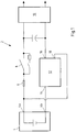
- Fig. 1 shows an equivalent circuit diagram of an on-board network 2 of a motor vehicle.
- a high-voltage battery 4 is shown as an example.
- the high-voltage battery 4 can in particular be a battery of a drive train of a vehicle.
- the B + pole 4a of the battery 4 is connected to a drive train 10 as a load via a series resistor 6 and an "ignition switch" 8. The switch 8 is closed during operation.
- the B pole 4b is connected to the load 10 via the fuse element 12 in question.
- the fuse element 12 has an input connection 14 and a first output connection 16 and a second output connection 18.
- the load path is formed via the input connection 14 and the output connection 16.
- the safety path is formed via the input connection 14 and the output connection 18.
- the output terminal 16 is connected to the load 10 and the output terminal 18 is connected to the B + pole 4a.
- the fuse element 12 is in the Fig. 2a shown in detail.
- the load path 20 connects the input connection 14 to the output connection 16.
- the load path 20 has a separating element 22 on which a predetermined breaking point 24 is arranged.
- the separating element 22 closes a housing 26.
- a flowable medium 28 is arranged in the housing 26.
- the housing 26 is formed in the manner of a channel in which a separating slide 30 is arranged.
- the separating slide 30 can be moved in the direction 32.
- the separating slide 30 is formed in two parts from an insulator 30a and a conductive element 30b.
- a drive 34 is arranged, which is designed as a pyrotechnic drive.
- the slide gate 30 When the drive 34 is activated, the slide gate 30 is accelerated in the direction 32. This leads to the flowable medium 28 exerting pressure on the predetermined breaking point 24 in such a way that it bursts. This is described below.
- the fuse path 36 is formed between the input connection 14 and the output connection 18.
- the slide valve 30 forms an electrical Separation along fuse path 36 by isolator 30a.
- a fuse 38 is arranged in the fuse path 36.
- Figure 2b shows the securing element 12 at the moment of activation.
- the drive 34 was activated by an external signal, for example an airbag control signal or the like. This leads to a force acting on the separating slide 30, so that it is accelerated in the direction 32. This leads to the fact that the medium 28 exerts such a pressure on the separating element 22 that the predetermined breaking point 24 bursts.
- This short circuit leads to a commutation of a current that may still flow via the isolating element 22, for example via an arc, to the fuse path 36.
- the fuse 38 is activated in the fuse path 36 via the commutated current.
- the fuse 38 melts and also separates the fuse path 36.
Landscapes
- Engineering & Computer Science (AREA)
- Power Engineering (AREA)
- Mechanical Engineering (AREA)
- Life Sciences & Earth Sciences (AREA)
- Sustainable Development (AREA)
- Sustainable Energy (AREA)
- Transportation (AREA)
- Fuses (AREA)
Description
- Der Gegenstand betrifft ein elektrisches Sicherungselement sowie Verfahren zum Betreiben eines elektrischen Sicherungselementes.
- Durch die zunehmende Elektrifizierung von Kraftfahrzeugen, nicht nur hinsichtlich des Antriebsstrangs, sondern auch hinsichtlich der steigenden Anzahl an Komfortverbrauchern, steigen nicht nur die Batterieströme, sondern werden auch zunehmend höhere Spannungsniveaus erreicht. Gerade im Bereich der Antriebstechnologie werden sehr hohe Batteriespannungen benötigt. Dies führt zu stetig steigenden Anforderungen an die jeweiligen Absicherungselemente hinsichtlich ihrer maximalen Trennströme, deren Spannungsfestigkeit sowie deren Fehlerwahrscheinlichkeit.
- Insbesondere in einem Fehlerfall, beispielsweise nach einem Crash, muss ein verlässliches Abschalten bzw. Trennen der Batterie vom restlichen Leitungsstrang in dem Fahrzeug sichergestellt sein. Durch die hohen Spannungen treten erhebliche Risiken für Insassen und Rettungspersonen auf, die verlässlich vermieden werden müssen. Um die Fehlerwahrscheinlichkeit zu verringern und die Sicherheit des elektrischen Systems eines Fahrzeugs zu erhöhen, werden neben aktiven Absicherungselementen auch passive Komponenten eingesetzt.
- Aktive Absicherungselemente sind Trennschalter, die durch einen Antrieb getrieben eine Leitung durchtrennen. Der Antrieb wird beispielsweise pyrotechnisch angesteuert. Insbesondere kann ein Trennsignal eine Aktivierung eines Antriebs bedeuten, woraufhin das aktive Trennelement getrennt wird.
- Passive Trennelemente sind beispielsweise Schmelzsicherungen, die basierend auf ihrem Wirkprinzip einen gewissen inneren Widerstand aufweisen müssen. Werden solche Schmelzsicherung in Reihe mit dem Lastpfad geschaltet, erzeugen diese eine relativ hohe Verlustleistung. Da naturgemäß ein gewisser elektrischer Widerstand in den Schmelzsicherungen vorhanden sein muss, ist eine Verlustleistung bei Verwendung einer Schmelzsicherung im Laststrang unvermeidlich.
- Auf der anderen Seite sind jedoch aktive Trennelemente aufgrund ihrer sehr schnellen mechanischen Trennung des Lastpfads anfällig gegenüber Lichtbögen. Brennt ein Lichtbogen über die Trennstelle, so kann nach wie vor ein hoher Strom fließen und eine sichere Trennung des Bordnetzes von der Batterie ist nicht gewährleistet.
WO-A-2017/042321 offenbart ein Sicherungselement nach dem Oberbegriff des Anspruchs 1. - Aus diesem Grunde lag dem Gegenstand die Aufgabe zugrunde, ein Sicherungselement zur Verfügung zu stellen, welches bei geringem Übergangswiderstand im Lastpfad eine sehr geringe Fehlerwahrscheinlichkeit aufweist.
- Diese Aufgabe wird durch ein Sicherungselement nach Anspruch 1, ein Fahrzeug nach Anspruch 12 sowie ein Verfahren nach Anspruch 14 gelöst.
- Zwischen der Batterie und den Verbrauchern, sei es Komfortverbraucher und/oder der Antriebsmotor, kann ein schaltbarer Lastpfad vorgesehen sein. Ein Lastpfad kann eine elektrische Leitung sein, entlang derer elektrischer Strom durch das Sicherungselement fließt.
- Zusätzlich zu dem Lastpfad kann ein schaltbarer Sicherungspfad vorgesehen sein. Ein Sicherungspfad kann eine elektrische Leitung sein, entlang derer elektrischer Strom durch das Sicherungselement fließt. Dadurch, dass der Sicherungspfad schaltbar ist, kann er im Normalbetrieb stromlos geschaltet sein. Insbesondere kann der Sicherungspfad im Normalbetrieb geöffnet sein.
- Eingangsseitig lassen sich Lastpfad und Sicherungspfad miteinander kurschließen, so dass das Sicherungselement insbesondere einen eingangsseitigen Anschluss aufweist. Von diesem Anschluss können Lastpfad und Sicherungspfad abzweigen. Auch können Sicherungspfad und Lastpfad eingangsseitig jeweils einen eigenen Anschluss aufweisen. Jedoch sind Sicherungspfad und Lastpfad dann bevorzugt in dem Sicherungselement miteinander kurz geschlossen.
- Ausgangsseitig können Lastpfad und Sicherungspfad voneinander getrennte Anschlüsse aufweisen.
- Der oder die eingangsseitigen Anschlüsse (der Eingang) des Sicherungselementes werden vorzugsweise mit einem Batteriepol, insbesondere dem B+ Pol oder dem B-Pol der Batterie verbunden.
- Der ausgangsseitige Anschluss des Lastpfads wird mit zumindest einer Last, insbesondere dem Antriebsstrang verbunden. Der ausgangsseitige Anschluss des Sicherungspfads wird mit einem jeweils zum eingangsseitigen Anschluss gegenpoligen Batteriepol verbunden.
- Da der Sicherungspfad im Normalbetrieb geöffnet ist, also stromlos ist, besteht zwischen dem Eingang und dem Ausgang des Sicherungspfads keine elektrische Verbindung und insbesondere ist in diesem Fall auch kein Kurzschluss der Batterie über den Sicherungspfad gegeben.
- Es ist nun erkannt worden, dass eine sichere Trennung, insbesondere unter Vermeidung eines Lichtbogens entlang der Trennstelle des Lastpfads dadurch gewährleistet werden kann, dass der Lastpfad und der Sicherungspfad derart miteinander in Wirkverbindung sind, dass ein elektrisches Öffnen des Lastpfads ein elektrisches Schließen des Sicherungspfads bewirkt und dass eine in dem Sicherungspfad angeordnete Sicherung im Moment des Schließens des Sicherungspfads auslöst.
- Gegenständlich wird eine Kombination einer aktiven und passiven Komponente ermöglicht. In dem Lastpfad kann eine aktive Komponente verbaut sein, die den Lastpfad aktiv öffnet. Gleichzeitig kann der Sicherungspfad geschlossen werden, was zu einem Auslösen der passiven Komponente in dem Sicherungspfad führt.
- Über den Sicherungspfad wird in dem Moment des Öffnens des Lastpfads ein hoher Strom geleitet. Insbesondere kommutiert der Strom des Lastpfads auf den Sicherungspfad. Dabei kann ein gegebenenfalls kurzzeitig über die Trennstelle des Lastpfads entlang eines Lichtbogens fließender Strom auf den Sicherungspfad kommutieren.
- Der Lastpfad ist im Normalbetrieb ein Kurzschluss zwischen dem Eingang und dem Ausgang des Sicherungselements. Der Widerstand über den Lastpfad ist nahezu null, so dass eine Verlustleistung im Normalbetrieb minimiert ist.
- Die Sicherung entlang des Sicherungspfads ist mit einem erhöhten elektrischen Widerstand versehen, dieser Widerstand hat jedoch im Normalbetrieb keine Auswirkungen, da der Sicherungspfad im Normalbetrieb geöffnet ist. Es fließt im Normalbetrieb kein Strom über den Sicherungspfad.
- Erst im Fehlerfall, d.h. bei einem Kurzschluss, einem Crash und/oder dem Defekt einer Batterie oder einem anderen Fehlerfall, wird der Lastpfad aktiv geöffnet und durch die Wirkverbindung zwischen Lastpfad und Sicherungspfad erfolgt ein Schließen des Sicherungspfads. Dieses Schließen des Sicherungspfads führt zu einer Aktivierung der Sicherung in dem Sicherungspfad durch den auf den Sicherungspfad kommutierenden Strom.
- Nachdem der Strom auf dem Sicherungspfad kommutiert ist, was zu einem sicheren Trennen des Lastpfads führt, wird auch der Strom in dem Sicherungspfad unmittelbar durch die darin angeordnete Sicherung getrennt. Das Sicherungselement stellt somit sicher, dass die Last, welche am Ausgang des Lastpfads angeschlossen ist, verlässlich von der Batterie getrennt wird.
- Wie bereits angedeutet, verfügt der Lastpfad gemäß einem Ausführungsbeispiel über eine Trennstelle. Die Trennstelle ist insbesondere eine Verjüngung, Sollbruchstelle oder dergleichen. Gemäß einem Ausführungsbeispiel ist die Trennstelle auch durch eine materialschlüssige Verbindung zwischen zwei miteinander verbundene Trennlaschen gebildet. Die Verbindung kann eine Löt- oder Schweißverbindung sein. Die Laschen, die die Trennstelle bilden, können einander zugewiesen sein.
- Gemäß einem Ausführungsbeispiel wird vorgeschlagen, dass ein aktiviertes Trennelement die Trennstelle trennt und gleichzeitig den Sicherungspfad schließt. Das Trennelement führt dazu, dass eine mechanische Wirkverbindung zwischen der Trennstelle und dem Sicherungspfad gebildet ist. Das Trennelement kann beispielsweise aus zumindest zwei Materialien gebildet sein. Dabei ist es möglich, dass ein erster Bereich des Trennelements durch ein Isolator gebildet ist und ein zweiter Bereich des Trennelements durch einen Leiter. Zunächst ist das Trennelement mit dem Isolator in dem Sicherungspfad angeordnet und führt dazu, dass der Sicherungspfad geöffnet ist. Wird das Trennelement bewegt, so kann der Isolator in Richtung der Trennstelle bewegt werden und gleichzeitig der Leiter des Trennelements den Sicherungspfad kurzschließen.
- Auch wird vorgeschlagen, dass das Trennelement einen mechanischen Antrieb aufweist. Dies ist insbesondere ein pyrotechnischer Antrieb. Ein pyrotechnischer Antrieb kann durch eine pyrotechnische Zündpille gebildet sein, die elektrisch aktivierbar ist. Beim Aktivieren der Zündpille wird ein Explosionsdruck aufgebaut, der das Trennelement beschleunigt. Dabei kann das Trennelement gleichzeitig sowohl ein Trennen der Trennstelle des Lastpfads als auch ein Schließen des Sicherungspfads bewirken. Insbesondere durch eine lineare Bewegung kann dies erfolgen.
- Gemäß einem Ausführungsbeispiel wird vorgeschlagen, dass das Trennelement einen Trennschieber aufweist. Der Trennschieber wird insbesondere durch den Antrieb in Richtung der Trennstelle des Lastpfads beschleunigt. Gleichzeitig wird diese Bewegung des Trennschiebers dazu führen, dass der Sicherungspfad geschlossen wird. Der Trennschieber kann ein ein- oder zweiteiliges Bauteil sein. Der Trennschieber wird insbesondere einheitlich beschleunigt, d.h. dass alle Bauelemente des Trennschiebers eine gleiche Beschleunigung durch den Antrieb erfahren.
- Gemäß einem Ausführungsbeispiel wird vorgeschlagen, dass der Trennschieber als in einem Gehäuse verschiebbarer Kolben gebildet ist. Das Gehäuse kann insbesondere den Antrieb, den Trennschieber und die Trennstelle aufweisen. Insbesondere kann das Gehäuse durch die Trennstelle bzw. die die Trennstelle bildenden Laschen verschlossen sein. In dem Gehäuse kann der Trennschieber linear bewegt werden. Der Kolben wird dabei in dem Gehäuse in Richtung der Trennstelle bewegt.
- Ist in dem Gehäuse zwischen dem Trennschieber und der Trennstelle ein fließfähiges Medium angeordnet, so wird dieses fließfähige Medium durch die Bewegung des Kolbens in Richtung der Trennstelle beschleunigt. Das fließfähige Medium ist bevorzugt inkompressibel, so dass die Beschleunigung des Kolbens in Richtung der Trennstelle dazu führt, dass an der Trennstelle ein Berstdruck überschritten wird und die Trennstelle aufbricht. Dies führt zu einem Trennen des Lastpfads an der Trennstelle. Das fließfähige Medium kann einen gegebenenfalls entstehenden Lichtbogen löschen. Auch kann das fließfähige Medium dazu geeignet sein, die Entstehung des Lichtbogens grundsätzlich zu unterbinden.
- Gemäß einem Ausführungsbeispiel wird vorgeschlagen, dass der Trennschieber ein Verbindungselement aufweist. Dieses Verbindungselement kann dazu geeignet sein, den Sicherungspfad zu schließen. Das Verbindungselement kann durch den Antrieb mechanisch zwischen zwei Anschlüssen des Sicherungspfads bewegt werden. Im Normalbetrieb ist der Sicherungspfad zwischen den zwei Anschlüssen geöffnet. Dabei kann insbesondere der Isolator des Trennschiebers zwischen den Anschlüssen angeordnet sein. Im Aktivierungsfall wird der Trennschieber linear bewegt. Dies kann dazu führen, dass der Isolator zwischen den Anschlüssen weg bewegt wird und das Verbindungselement zwischen die Anschlüsse bewegt wird. Das führt dazu, dass das Verbindungselement den Sicherungspfad schließt.
- Gemäß einem Ausführungsbeispiel wird vorgeschlagen, dass das Trennelement ein fließfähiges Medium aufweist. Wie bereits erläutert, kann das fließfähige Medium, welches insbesondere inkompressibel ist, durch einen Antrieb in Richtung der Trennstelle beschleunigt werden. Dadurch entsteht an der Trennstelle ein Druck, der zum Trennen der Trennstelle führt.
- Gemäß einem Ausführungsbeispiel wird vorgeschlagen, dass nach Aktivierung des Antriebs die Anschlüsse des Sicherungspfads durch das Verbindungselement kurzgeschlossen sind. Dann kann der Strom, der zunächst über den Lastpfad fließt, auf den Sicherungspfad kommutieren.
- Gemäß einem Ausführungsbeispiel wird vorgeschlagen, dass die Sicherung in dem Sicherungspfad eine Schmelzsicherung ist. Wird über den Sicherungspfad ein ausreichend hoher Strom geführt, schmilzt die Schmelzsicherung und trennt den Sicherungspfad.
- Dadurch, dass der Strom auf den Sicherungspfad kommutiert, wird zunächst der Lastpfad sicher getrennt. Anschließend wird der Sicherungspfad sicher durch die Schmelzsicherung geöffnet. Danach ist die Batterie vollständig von dem Bordnetz getrennt.
- Der Sicherungspfad kann als Kurzschluss zwischen zwei Polen einer Batterie geschaltet sein. Im Normalbetrieb ist der Sicherungspfad geöffnet und die Batterie somit nicht kurzgeschlossen. Im Aktivierungsfall führt der Kurzschluss jedoch dazu, dass der Widerstand zwischen dem Batteriepol, der mit dem Eingang des Sicherungselements verbunden ist und dem Batteriepol, der mit dem Ausgang des Sicherungspfads verbunden ist, erheblich geringer ist, als der Widerstand zwischen dem Pol an dem Eingang des Sicherungselements und dem über den Lastpfad und die Last angeschlossenen Batteriepol. Dies führt zu einem sicheren Kommutieren des Stroms von dem Lastpfad, der getrennt wird, auf den Sicherungspfad und einem anschließenden Trennen der Sicherung in dem Sicherungspfad.
- Gemäß einem Ausführungsbeispiel wird vorgeschlagen, dass der Lastpfad zwischen einem Pol einer Batterie und zumindest einer mit dem anderen Pol der Batterie verbundenen Last geschaltet ist. Im Normalbetrieb wird die Last somit über den Lastpfad bei sehr geringen Leitungsverlusten versorgt. Das Sicherungselement im Sicherungspfad ist inaktiv und stromlos. Erst im Aktivierungsfall wird das Sicherungselement im Sicherungspfad bestromt. Dadurch öffnet der Sicherungspfad, so dass ein sicheres Trennen durch das Sicherungselement gewährleistet ist.
- Gemäß einem Ausführungsbeispiel wird vorgeschlagen, dass das fließfähige Medium eine Flüssigkeit oder ein rieselfähiges Schüttgut, insbesondere Sand ist und/oder dass das fließfähige Medium flüssig, pastös, schaumförmig, gelförmig oder gekörnt ist. Insbesondere ist das fließfähige Medium inkompressibel.
- Um ein Lichtbogen an der Trennstelle des Lastpfads zu unterbinden oder zu löschen, ist das fließfähige Medium gemäß einem Ausführungsbeispiel mit elektrisch isolierenden Eigenschaften ausgestattet. Auch kann das fließfähige Medium mit Lichtbogen löschenden Eigenschaften ausgestattet sein.
- Ein weiterer Aspekt ist ein Fahrzeug nach Anspruch 12.
- In dem Fahrzeug ist eine elektrische Energiequelle vorgesehen. Ein erster Pol der als Fahrzeugbatterie gebildeten Energiequelle wird mit dem Eingangsanschluss des Sicherungselements verbunden. Der andere Pol wird einerseits mit dem Ausgangsanschluss des Sicherungspfads verbunden und andererseits mit der Last, welche an dem ausgangsseitigen Anschluss des Lastpfads angeschlossen ist. Somit ist ein erster Stromkreis über den ersten Pol, den Lastpfad, die Last und den zweiten Pol gebildet. Ein zweiter, geöffneter Stromkreis ist über den ersten Pol, den Sicherungspfad und den zweiten Pol gebildet. Dieser zweite Stromkreis ist im Normalfall geöffnet und wird, wie oben beschrieben, im Aktivierungsfall geschlossen und bildet somit einen Kurzschluss über die beiden Batteriepole. Dies sichert das Kommutieren des Stroms von der Trennstelle auf den Sicherungspfad.
- Gemäß einem weiteren Aspekt wird ein Verfahren zum Trennen eines Lastpfads mit Hilfe eines elektrischen Sicherungselements vorgeschlagen. Im Fehlerbetrieb wird der Lastpfad geöffnet und gleichzeitig der Sicherungspfad geschlossen. Dies führt dazu, dass der über den Lastpfad fließende Strom auf den Sicherungspfad kommutiert und dadurch eine in dem Sicherungspfad angeordnete Sicherung auslöst und den Sicherungspfad öffnet.
- Nachfolgend wird der Gegenstand anhand einer Ausführungsbeispiele zeigenden Zeichnung näher erläutert. In der Zeichnung zeigen:
- Fig. 1
- ein Ersatzschaltbild eines Bordnetzes mit einem gegenständlichen Sicherungselement;
- Fig. 2a
- ein gegenständliches Sicherungselement im Normalzustand;
- Fig. 2b
- ein Sicherungselement während der Aktivierung;
- Fig. 2c
- ein Sicherungselement im Auslösezustand.
-
Fig. 1 zeigt ein Ersatzschaltbild eines Bordnetzes 2 eines Kraftfahrzeugs. Beispielhaft ist eine Hochvoltbatterie 4 dargestellt. Die Hochvoltbatterie 4 kann insbesondere eine Batterie eines Antriebsstrangs eines Fahrzeugs sein. Der B+ Pol 4a der Batterie 4 ist über einen Vorwiderstand 6 sowie einen "Zündschalter" 8 mit einem Antriebsstrang 10 als Last verbunden. Im Betrieb ist der Schalter 8 geschlossen. - Der B- Pol 4b ist über das gegenständliche Sicherungselement 12 mit der Last 10 verbunden. Das Sicherungselement 12 hat einen Eingangsanschluss 14 sowie einen ersten Ausgangsanschluss 16 und einen zweiten Ausgangsanschluss 18. Der Lastpfad ist über den Eingangsanschluss 14 und den Ausgangsanschluss 16 gebildet. Der Sicherungspfad ist über den Eingangsanschluss 14 und den Ausgangsanschluss 18 gebildet. Der Ausgangsanschluss 16 ist mit der Last 10 verbunden und der Ausgangsanschluss 18 ist mit dem B+ Pol 4a verbunden.
- Das Sicherungselement 12 ist in der
Fig. 2a im Detail dargestellt. Der Lastpfad 20 verbindet den Eingangsanschluss 14 mit dem Ausgangsanschluss 16. Der Lastpfad 20 weist ein Trennelement 22 auf, an dem eine Sollbruchstelle 24 angeordnet ist. Das Trennelement 22 verschließt ein Gehäuse 26. In dem Gehäuse 26 ist ein fließfähiges Medium 28 angeordnet. - Das Gehäuse 26 ist in der Art eines Kanals gebildet, in dem ein Trennschieber 30 angeordnet ist. Der Trennschieber 30 lässt sich in Richtung 32 bewegen. Der Trennschieber 30 ist zweiteilig aus einem Isolator 30a und einem leitenden Element 30b gebildet.
- In dem Kanal, vor dem Trennschieber 30 ist ein Antrieb 34 angeordnet, der als pyrotechnischer Antrieb gebildet ist.
- Bei einer Aktivierung des Antriebs 34 wird der Trennschieber 30 in Richtung 32 beschleunigt. Dies führt dazu, dass das fließfähige Medium 28 einen Druck auf die Sollbruchstelle 24 derart ausübt, dass diese birst. Dies wird nachfolgend noch beschrieben.
- Der Sicherungspfad 36 ist zwischen dem Eingangsanschluss 14 und dem Ausgangsanschluss 18 gebildet. Der Trennschieber 30 bildet eine elektrische Trennung entlang des Sicherungspfads 36 durch den Isolator 30a. In dem Sicherungspfad 36 ist eine Schmelzsicherung 38 angeordnet.
-
Fig. 2b zeigt das Sicherungselement 12 im Moment der Aktivierung. Der Antrieb 34 wurde durch ein externes Signal, beispielsweise ein Airbagsteuersignal oder dergleichen aktiviert. Dies führt dazu, dass eine Kraft auf den Trennschieber 30 wirkt, so dass dieser in Richtung 32 beschleunigt wird. Dies führt dazu, dass das Medium 28 einen derartigen Druck auf das Trennelement 22 ausübt, dass die Sollbruchstelle 24 birst. - Gleichzeitig führt die Bewegung des Trennschiebers 30 in dem Gehäuse 26 dazu, dass der Leiter 30b den Sicherungspfad 36 schließt. Dieses Schließen des Sicherungspfads 36 führt zu einem Kurzschluss zwischen dem Eingangsanschluss 14 und dem Ausgangsanschluss 18 und mithin, wie aus der
Fig. 1 zu entnehmen ist, zwischen dem B+ Pol 4a und dem B- Pol 4b der Batterie 4. - Dieser Kurzschluss führt zu einer Kommutierung eines gegebenenfalls noch über das Trennelement 22 fließenden Stroms, beispielsweise über einen Lichtbogen, auf den Sicherungspfad 36. In dem Sicherungspfad 36 wird über den kommutierten Strom die Schmelzsicherung 38 aktiviert. Die Schmelzsicherung 38 schmilzt auf und trennt den Sicherungspfad 36 ebenfalls auf.
- Dies führt zu der Situation in Fig. 2c, in der zu erkennen ist, dass sowohl der Lastpfad 20 als auch der Sicherungspfad 36 stromlos ist. Die Last 10 ist somit vollständig von der Batterie 4 getrennt.
-
- 2
- Bordnetz
- 4
- Hochvoltbatterie
- 4a
- B+ Pol
- 4b
- B- Pol
- 6
- Widerstand
- 8
- Schalter
- 10
- Last
- 12
- Sicherungselement
- 14
- Eingangsanschluss
- 16, 18
- Ausgangsanschluss
- 20
- Lastpfad
- 22
- Trennelement
- 24
- Sollbruchstelle
- 26
- Gehäuse
- 28
- Medium
- 30
- Trennschieber
- 30a
- Isolator
- 30b
- Leiter
- 32
- Richtung
- 34
- Antrieb
- 36
- Sicherungspfad
- 38
- Schmelzsicherung
Claims (14)
- Elektrisches Sicherungselement (12) umfassend,- einen schaltbaren Lastpfad (20) und- einen schaltbaren Sicherungspfad (36), wobei- der Lastpfad (20) und der Sicherungspfad (36) mit ihren jeweiligen Eingängen miteinander kurzgeschlossen sind,dadurch gekennzeichnet,- dass der Lastpfad (20) und der Sicherungspfad (36) derart miteinander in Wirkverbindung sind, dass ein elektrisches Öffnen des Lastpfads (20) ein elektrisches Schließen des Sicherungspfads (36) bewirkt und dass eine in dem Sicherungspfad (36) angeordnete Sicherung (38) im Moment des Schließens des Sicherungspfads (36) auslöst.
- Sicherungselement nach Anspruch 1,
dadurch gekennzeichnet,- dass in dem Lastpfad (20) eine Sollbruchstelle (24) angeordnet ist. - Sicherungselement nach Anspruch 1 oder 2,
dadurch gekennzeichnet,- dass ein aktiviertes Trennelement (22) die Sollbruchstelle (24) trennt und gleichzeitig den Sicherungspfad (36) schließt. - Sicherungselement nach Anspruch 3, dadurch gekennzeichnet,- dass das Trennelement (22) einen Antrieb (34), insbesondere einen pyrotechnischen Antrieb aufweist.
- Sicherungselement nach Anspruch 4, dadurch gekennzeichnet,- dass das Trennelement (22) einen Trennschieber (30) aufweist, welcher durch den Antrieb (34) in Richtung der Sollbruchstelle (24) des Lastpfads (20) beschleunigt wird, wobei die Bewegung des Trennschiebers (30) ein Schließen des Sicherungspfads (36) bewirkt.
- Sicherungselement nach Anspruch 5, dadurch gekennzeichnet,- dass der Trennschieber (30) als in einem Gehäuse (26) verschiebbarer Kolben gebildet ist, wobei der Kolben ein zumindest zwischen der Sollbruchstelle (24) und dem Trennschieber (30) angeordnetes fließfähiges Medium (28) in Richtung der Sollbruchstelle (24) beschleunigt. und- dass der Trennschieber (30) einen Leiter (30b) aufweist, wobei der Leiter (30b) durch den Antrieb (34) zwischen zwei Anschlüsse (14, 18) des Sicherungspfads (36) beweglich ist.
- Sicherungselement nach Anspruch 3, dadurch gekennzeichnet,- dass das Trennelement (22) ein fließfähiges Medium (28) aufweist, wobei das fließfähige Medium (28) durch einen Antrieb (34) in Richtung der Sollbruchstelle (24) beschleunigt wird und ein dadurch auf die Sollbruchstelle (24) wirkender Druck die Sollbruchstelle (24) trennt.
- Sicherungselement nach Anspruch 6, dadurch gekennzeichnet,- dass der Leiter (30b) nach Aktivierung des Antriebs (34) die Anschlüsse (14, 18) des Sicherungspfads (36) kurzschließt.
- Sicherungselement nach einem der vorangehenden Ansprüche,
dadurch gekennzeichnet,- dass der Sicherungspfad (36) als Kurzschluss zwischen zwei Polen einer Batterie geschaltet ist. - Sicherungselement nach einem der vorangehenden Ansprüche,
dadurch gekennzeichnet,- dass der Lastpfad (20) zwischen einem Pol einer Batterie und zumindest einer mit dem anderen Pol der Batterie verbundenen Last geschaltet ist. - Sicherungselement nach einem der Ansprüche 6 oder 8, dadurch gekennzeichnet, dass das fließfähige Medium (28) eine Flüssigkeit oder ein rieselfähiges Schüttgut, insbesondere Sand, ist und/oder dass das fließfähige Medium (28) flüssig, pastös, schaumförmig, gelförmig oder gekörnt ist insbesondere- dass das fließfähige Medium (28) elektrisch isolierende Eigenschaften aufweist und/oder einen Lichtbogen löschende Eigenschaften aufweist.
- Fahrzeug, umfassend:- ein Bordnetz (2), und- ein elektrisches Sicherungselement nach einem der Ansprüche 1 bis 11.
- Fahrzeug nach Anspruch 12,
dadurch gekennzeichnet,
dass eine Fahrzeugbatterie (4) als elektrische Energiequelle vorgesehen ist und dass die Fahrzeugbatterie (4) mit einem Pol (4a) an den Eingangsanschluss des Sicherungselements und mit dem anderen Pol (4b) an den Ausgangsanschluss des Sicherungspfads angeschlossen ist. - Verfahren zum Trennen eines Lastpfads mit Hilfe eines elektrischen Sicherungselements nach einem der Ansprüche 1 bis 11, vorzugsweise in einem Fahrzeug nach Anspruch 12 oder 13,
dadurch gekennzeichnet,
dass im Fehlerbetrieb der Lastpfad (20) geöffnet und gleichzeitig der Sicherungspfad (36) geschlossen wird, derart, dass der über den Lastpfad (20) fließende Strom auf den Sicherungspfad (36) kommutiert und dadurch eine in dem Sicherungspfad (36) angeordnete Sicherung (38) auslöst und den Sicherungspfad (36) öffnet.
Applications Claiming Priority (2)
| Application Number | Priority Date | Filing Date | Title |
|---|---|---|---|
| DE102017125208.8A DE102017125208B4 (de) | 2017-10-27 | 2017-10-27 | Elektrisches Sicherungselement sowie Verfahren zum Betreiben eines elektrischen Sicherungselementes |
| PCT/EP2018/075032 WO2019081128A1 (de) | 2017-10-27 | 2018-09-17 | Elektrisches sicherungselement sowie verfahren zum betreiben eines elektrischen sicherungselementes |
Publications (2)
| Publication Number | Publication Date |
|---|---|
| EP3701557A1 EP3701557A1 (de) | 2020-09-02 |
| EP3701557B1 true EP3701557B1 (de) | 2021-06-02 |
Family
ID=63708306
Family Applications (1)
| Application Number | Title | Priority Date | Filing Date |
|---|---|---|---|
| EP18779259.3A Active EP3701557B1 (de) | 2017-10-27 | 2018-09-17 | Elektrisches sicherungselement sowie verfahren zum betreiben eines elektrischen sicherungselementes |
Country Status (7)
| Country | Link |
|---|---|
| US (1) | US11239039B2 (de) |
| EP (1) | EP3701557B1 (de) |
| CN (1) | CN111386587B (de) |
| DE (1) | DE102017125208B4 (de) |
| ES (1) | ES2879327T3 (de) |
| MX (1) | MX2020004278A (de) |
| WO (1) | WO2019081128A1 (de) |
Families Citing this family (11)
| Publication number | Priority date | Publication date | Assignee | Title |
|---|---|---|---|---|
| DE102017011631B4 (de) * | 2017-12-15 | 2020-02-13 | Panasonic Industrial Devices Europe Gmbh | Vorrichtung zum Unterbrechen eines elektrischen Stromkreises |
| FR3098006B1 (fr) * | 2019-06-25 | 2021-07-09 | Mersen France Sb Sas | Coupe-circuit électrique |
| JP7390550B2 (ja) * | 2019-10-04 | 2023-12-04 | パナソニックIpマネジメント株式会社 | 遮断装置 |
| DE102020104935A1 (de) * | 2020-02-25 | 2021-08-26 | Bayerische Motoren Werke Aktiengesellschaft | Abschalteinrichtung, Hochvoltbordnetz sowie Kraftfahrzeug |
| GB2593941A (en) * | 2020-04-08 | 2021-10-13 | Eaton Intelligent Power Ltd | Disconnect device with integrated fuse |
| FR3112889A1 (fr) * | 2020-07-24 | 2022-01-28 | Ncs Pyrotechnie Et Technologies Sas | Coupe circuit pyrotechnique |
| CN112447461A (zh) * | 2020-12-11 | 2021-03-05 | 西安中熔电气股份有限公司 | 一种依次断开导体和熔体的激励熔断器 |
| FR3120155A1 (fr) | 2021-02-25 | 2022-08-26 | Mersen France Sb Sas | Appareil électrique, système électrique de coupure comportant un tel appareil |
| US12145431B2 (en) | 2021-11-23 | 2024-11-19 | Polestar Performance Ab | Pyrotechnic brackets for electric vehicle |
| KR20250088683A (ko) * | 2022-10-19 | 2025-06-17 | 센사타 테크놀로지스, 인크 | 빠른 단선을 갖춘 퓨즈식 단일 지점 고전압 접촉기 |
| EP4625458A1 (de) * | 2024-03-26 | 2025-10-01 | Miba Resistors Austria GmbH | Elektrische schaltung mit einem elektrischen bauelement sowie dieses elektrische bauelement |
Family Cites Families (38)
| Publication number | Priority date | Publication date | Assignee | Title |
|---|---|---|---|---|
| FR2217786B1 (de) | 1971-05-26 | 1976-10-29 | France Etat | |
| US3763454A (en) * | 1972-02-22 | 1973-10-02 | Tektronix Inc | Thermal switch |
| US3828289A (en) * | 1973-07-23 | 1974-08-06 | American Thermostat Corp | Combined current and temperature sensitive fuse assembly |
| US3958206A (en) * | 1975-06-12 | 1976-05-18 | General Electric Company | Chemically augmented electrical fuse |
| US4224487A (en) * | 1978-02-23 | 1980-09-23 | Simonsen Bent P | Fast acting explosive circuit interrupter |
| US5535842A (en) * | 1993-03-05 | 1996-07-16 | Volkswagen Ag | Safety arrangement for collision-related disconnection of an electrical energy source from a motor vehicle supply circuit |
| DE19503809B4 (de) * | 1995-02-06 | 2005-01-20 | Bayerische Motoren Werke Ag | Sicherungsvorrichtung für eine Stromleitung in Fahrzeugen |
| US5793275A (en) * | 1995-10-23 | 1998-08-11 | Iversen; Arthur H. | Exothermically assisted arc limiting fuses |
| US6295930B1 (en) * | 1998-01-08 | 2001-10-02 | Harness System Technologies Research, Ltd. | Circuit breaker |
| DE19809149C2 (de) * | 1998-03-04 | 2001-09-27 | Trw Automotive Electron & Comp | Sicherung, insbesondere für die Kraftfahrzeugtechnik |
| DE19835781C2 (de) * | 1998-08-07 | 2002-10-24 | Daimler Chrysler Ag | Verfahren und Vorrichtung zur Auslösung einer Sicherung für elektrische Leiter in einem Kraftfahrzeug |
| JP2001006518A (ja) * | 1999-04-23 | 2001-01-12 | Sony Chem Corp | 過電流保護装置 |
| JP2001052584A (ja) * | 1999-08-03 | 2001-02-23 | Yazaki Corp | 回路遮断装置 |
| JP3797590B2 (ja) * | 1999-08-25 | 2006-07-19 | 矢崎総業株式会社 | 電源遮断器 |
| DE10052545A1 (de) * | 2000-10-23 | 2002-05-02 | Peter Lell | Pyrotechnisches Sicherungselement |
| US6759760B2 (en) * | 2002-06-21 | 2004-07-06 | Daimlerchrysler Corporation | Method to eliminate shipping fuse handling |
| US20040041682A1 (en) * | 2002-08-29 | 2004-03-04 | Pasha Brian D. | Battery circuit disconnect device |
| JP2004214033A (ja) * | 2002-12-27 | 2004-07-29 | Sony Chem Corp | 保護素子 |
| DE502004005631D1 (de) * | 2003-02-04 | 2008-01-17 | Delphi Tech Inc | Pyromechanisches Trennelement |
| KR100851478B1 (ko) * | 2003-08-08 | 2008-08-08 | 델피 테크놀로지스 인코포레이티드 | 회로 차단 장치와, 전기 회로의 접속을 위한 안전 장치와, 전기 회로의 안전을 향상시키는 방법 |
| US7239225B2 (en) * | 2003-10-17 | 2007-07-03 | Special Devices, Inc. | Pyrotechnic circuit breaker |
| US7394636B2 (en) | 2005-05-25 | 2008-07-01 | International Business Machines Corporation | Slave mode thermal control with throttling and shutdown |
| JP4514669B2 (ja) * | 2005-07-29 | 2010-07-28 | エヌイーシー ショット コンポーネンツ株式会社 | 温度ヒューズを用いた保護装置 |
| JP5072796B2 (ja) * | 2008-05-23 | 2012-11-14 | ソニーケミカル&インフォメーションデバイス株式会社 | 保護素子及び二次電池装置 |
| JP5359982B2 (ja) * | 2009-06-29 | 2013-12-04 | 豊田合成株式会社 | 車両の電気回路遮断装置 |
| CN101902027B (zh) | 2009-09-04 | 2013-02-13 | 中国人民解放军海军工程大学 | 电弧触发型混合限流熔断器 |
| FR2953324B1 (fr) * | 2009-11-27 | 2012-06-08 | Snpe Materiaux Energetiques | Interrupteur electrique a tiroir coulissant formant coupe-circuit ou commutateur |
| CN201622983U (zh) * | 2010-01-28 | 2010-11-03 | 比亚迪股份有限公司 | 一种快速大电流保险装置 |
| DE102010011150B4 (de) | 2010-03-11 | 2012-03-29 | Auto-Kabel Managementgesellschaft Mbh | Elektrische Sicherung für Kraftfahrzeugenergieleitungen und Herstellungsverfahren für eine solche Sicherung |
| TWI488208B (zh) * | 2011-08-18 | 2015-06-11 | Ind Tech Res Inst | 保護元件及應用此保護元件之保護裝置 |
| DE102012013491B3 (de) * | 2012-07-09 | 2013-09-26 | Auto-Kabel Managementgesellschaft Mbh | Elektrische Trennvorrichtung mit Sensorüberwachung |
| DE102012015322A1 (de) * | 2012-08-02 | 2014-05-15 | Infineon Technologies Ag | Fahrzeugspannungsversorgung |
| KR101401141B1 (ko) * | 2012-11-26 | 2014-05-30 | 스마트전자 주식회사 | 비정상상태의 전류 및 전압을 차단하는 복합보호소자 |
| DE102015200507A1 (de) * | 2015-01-15 | 2016-07-21 | Volkswagen Aktiengesellschaft | Schalt- und Schutzeinrichtung für Hochvolt-Bordnetze |
| DE102015107579B3 (de) | 2015-05-13 | 2016-08-04 | Lisa Dräxlmaier GmbH | Sicherung mit Explosionskammer |
| JP6413931B2 (ja) * | 2015-05-29 | 2018-10-31 | 豊田合成株式会社 | 導通遮断装置 |
| FR3041143B1 (fr) * | 2015-09-10 | 2017-10-20 | Mersen France Sb Sas | Dispositif de protection pour un circuit electrique, circuit electrique equipe d'un tel dispositif et procede de protection d'un tel circuit electrique |
| DE102016222339A1 (de) * | 2016-11-15 | 2018-05-17 | Bayerische Motoren Werke Aktiengesellschaft | Pyrotechnischer schalter und zwischenkreis-entladungssystem |
-
2017
- 2017-10-27 DE DE102017125208.8A patent/DE102017125208B4/de active Active
-
2018
- 2018-09-17 CN CN201880070107.XA patent/CN111386587B/zh active Active
- 2018-09-17 EP EP18779259.3A patent/EP3701557B1/de active Active
- 2018-09-17 ES ES18779259T patent/ES2879327T3/es active Active
- 2018-09-17 US US16/758,146 patent/US11239039B2/en active Active
- 2018-09-17 MX MX2020004278A patent/MX2020004278A/es unknown
- 2018-09-17 WO PCT/EP2018/075032 patent/WO2019081128A1/de not_active Ceased
Also Published As
| Publication number | Publication date |
|---|---|
| CN111386587B (zh) | 2022-10-11 |
| ES2879327T3 (es) | 2021-11-22 |
| EP3701557A1 (de) | 2020-09-02 |
| US20200286703A1 (en) | 2020-09-10 |
| WO2019081128A1 (de) | 2019-05-02 |
| DE102017125208B4 (de) | 2021-08-12 |
| MX2020004278A (es) | 2020-07-29 |
| US11239039B2 (en) | 2022-02-01 |
| DE102017125208A1 (de) | 2019-05-02 |
| CN111386587A (zh) | 2020-07-07 |
Similar Documents
| Publication | Publication Date | Title |
|---|---|---|
| EP3701557B1 (de) | Elektrisches sicherungselement sowie verfahren zum betreiben eines elektrischen sicherungselementes | |
| EP3408127B1 (de) | Hochvoltbordnetzsystem mit einer pyrotechnischen trennvorrichtung, und verfahren zum betreiben des hochvoltbordnetzsystems | |
| EP3102454B1 (de) | Hochvoltbordnetz eines kraftfahrzeugs | |
| EP3785285B1 (de) | Hochvoltschalter, hochvoltbordnetz in einem kraftfahrzeug und verfahren zum betreiben eines hochvoltschalters | |
| DE102016107707B3 (de) | Schutzvorrichtung für eine Hochvolt-Spannungsversorgung | |
| DE102016213072B4 (de) | Ein Hochvolt-Batteriesystem mit Sicherungseinrichtung | |
| DE102011103834B4 (de) | Schaltsystem für kraftfahrzeugenergieleiter, mit einem solchen schaltsystem ausgestattetes kraftfahrzeug sowie verfahren zum trennen eines strompfades | |
| WO2018091307A1 (de) | Pyrotechnischer schalter und zwischenkreis-entladungssystem | |
| WO2018095602A1 (de) | Trennvorrichtung mit lichtbogenunterbrechung | |
| DE202015106793U1 (de) | Schmelzsicherung | |
| DE102017122008A1 (de) | Elektrischer schalter | |
| DE102017205833B4 (de) | Schaltschütz-Einrichtung für ein Kraftfahrzeug, Bordnetz für ein Kraftfahrzeug und Verfahren zum Überführen einer Schaltschütz-Einrichtung von einem geschlossenen Zustand in einen geöffneten Zustand | |
| WO2009052953A1 (de) | Brennstoffzellensystem mit zumindest einer brennstoffzelle | |
| DE102015225521B4 (de) | Vorrichtung zum Schalten eines elektrischen Stromkreises, Fahrzeug mit einer solchen Vorrichtung sowie ein Verfahren zu deren Betrieb | |
| DE102011106855B4 (de) | Verfahren und Vorrichtung zum Schutz einer Traktionsbatterie | |
| DE10017455C2 (de) | Schutzvorrichtung für ein Stromkabel in einem Kraftfahrzeug | |
| DE19741828A1 (de) | Elektrischer Sicherheitsschalter für Kraftfahrzeuge | |
| EP3549150B1 (de) | Vorrichtung zum trennen eines bordnetzes von einer energiequelle | |
| DE102019213390A1 (de) | Verfahren zur Ansteuerung eines elektrischen Schalters | |
| DE102018133277B4 (de) | Ansteuervorrichtung, trennsystem und verfahren | |
| EP4450317A1 (de) | Lade-/entladevorrichtung, speichervorrichtung, fahrzeug und verfahren zum betreiben der lade-/entladevorrichtung | |
| DE202018100802U1 (de) | Bistabiler Schalter | |
| EP4105960A1 (de) | Sicherungseinrichtung für ein elektrisches energieversorgungsnetz | |
| WO2025180818A1 (de) | Elektrische schalteinheit mit sicherungseinrichtung |
Legal Events
| Date | Code | Title | Description |
|---|---|---|---|
| STAA | Information on the status of an ep patent application or granted ep patent |
Free format text: STATUS: UNKNOWN |
|
| STAA | Information on the status of an ep patent application or granted ep patent |
Free format text: STATUS: THE INTERNATIONAL PUBLICATION HAS BEEN MADE |
|
| PUAI | Public reference made under article 153(3) epc to a published international application that has entered the european phase |
Free format text: ORIGINAL CODE: 0009012 |
|
| STAA | Information on the status of an ep patent application or granted ep patent |
Free format text: STATUS: REQUEST FOR EXAMINATION WAS MADE |
|
| 17P | Request for examination filed |
Effective date: 20200421 |
|
| AK | Designated contracting states |
Kind code of ref document: A1 Designated state(s): AL AT BE BG CH CY CZ DE DK EE ES FI FR GB GR HR HU IE IS IT LI LT LU LV MC MK MT NL NO PL PT RO RS SE SI SK SM TR |
|
| AX | Request for extension of the european patent |
Extension state: BA ME |
|
| GRAP | Despatch of communication of intention to grant a patent |
Free format text: ORIGINAL CODE: EPIDOSNIGR1 |
|
| STAA | Information on the status of an ep patent application or granted ep patent |
Free format text: STATUS: GRANT OF PATENT IS INTENDED |
|
| DAV | Request for validation of the european patent (deleted) | ||
| DAX | Request for extension of the european patent (deleted) | ||
| INTG | Intention to grant announced |
Effective date: 20210113 |
|
| GRAS | Grant fee paid |
Free format text: ORIGINAL CODE: EPIDOSNIGR3 |
|
| GRAA | (expected) grant |
Free format text: ORIGINAL CODE: 0009210 |
|
| STAA | Information on the status of an ep patent application or granted ep patent |
Free format text: STATUS: THE PATENT HAS BEEN GRANTED |
|
| REG | Reference to a national code |
Ref country code: CH Ref legal event code: EP |
|
| AK | Designated contracting states |
Kind code of ref document: B1 Designated state(s): AL AT BE BG CH CY CZ DE DK EE ES FI FR GB GR HR HU IE IS IT LI LT LU LV MC MK MT NL NO PL PT RO RS SE SI SK SM TR |
|
| REG | Reference to a national code |
Ref country code: GB Ref legal event code: FG4D Free format text: NOT ENGLISH |
|
| REG | Reference to a national code |
Ref country code: AT Ref legal event code: REF Ref document number: 1399223 Country of ref document: AT Kind code of ref document: T Effective date: 20210615 |
|
| REG | Reference to a national code |
Ref country code: IE Ref legal event code: FG4D Free format text: LANGUAGE OF EP DOCUMENT: GERMAN |
|
| REG | Reference to a national code |
Ref country code: DE Ref legal event code: R096 Ref document number: 502018005567 Country of ref document: DE |
|
| REG | Reference to a national code |
Ref country code: LT Ref legal event code: MG9D |
|
| PG25 | Lapsed in a contracting state [announced via postgrant information from national office to epo] |
Ref country code: FI Free format text: LAPSE BECAUSE OF FAILURE TO SUBMIT A TRANSLATION OF THE DESCRIPTION OR TO PAY THE FEE WITHIN THE PRESCRIBED TIME-LIMIT Effective date: 20210602 Ref country code: LT Free format text: LAPSE BECAUSE OF FAILURE TO SUBMIT A TRANSLATION OF THE DESCRIPTION OR TO PAY THE FEE WITHIN THE PRESCRIBED TIME-LIMIT Effective date: 20210602 Ref country code: HR Free format text: LAPSE BECAUSE OF FAILURE TO SUBMIT A TRANSLATION OF THE DESCRIPTION OR TO PAY THE FEE WITHIN THE PRESCRIBED TIME-LIMIT Effective date: 20210602 Ref country code: BG Free format text: LAPSE BECAUSE OF FAILURE TO SUBMIT A TRANSLATION OF THE DESCRIPTION OR TO PAY THE FEE WITHIN THE PRESCRIBED TIME-LIMIT Effective date: 20210902 |
|
| REG | Reference to a national code |
Ref country code: NL Ref legal event code: MP Effective date: 20210602 |
|
| REG | Reference to a national code |
Ref country code: ES Ref legal event code: FG2A Ref document number: 2879327 Country of ref document: ES Kind code of ref document: T3 Effective date: 20211122 |
|
| PG25 | Lapsed in a contracting state [announced via postgrant information from national office to epo] |
Ref country code: GR Free format text: LAPSE BECAUSE OF FAILURE TO SUBMIT A TRANSLATION OF THE DESCRIPTION OR TO PAY THE FEE WITHIN THE PRESCRIBED TIME-LIMIT Effective date: 20210903 Ref country code: NO Free format text: LAPSE BECAUSE OF FAILURE TO SUBMIT A TRANSLATION OF THE DESCRIPTION OR TO PAY THE FEE WITHIN THE PRESCRIBED TIME-LIMIT Effective date: 20210902 Ref country code: LV Free format text: LAPSE BECAUSE OF FAILURE TO SUBMIT A TRANSLATION OF THE DESCRIPTION OR TO PAY THE FEE WITHIN THE PRESCRIBED TIME-LIMIT Effective date: 20210602 Ref country code: PL Free format text: LAPSE BECAUSE OF FAILURE TO SUBMIT A TRANSLATION OF THE DESCRIPTION OR TO PAY THE FEE WITHIN THE PRESCRIBED TIME-LIMIT Effective date: 20210602 Ref country code: RS Free format text: LAPSE BECAUSE OF FAILURE TO SUBMIT A TRANSLATION OF THE DESCRIPTION OR TO PAY THE FEE WITHIN THE PRESCRIBED TIME-LIMIT Effective date: 20210602 Ref country code: SE Free format text: LAPSE BECAUSE OF FAILURE TO SUBMIT A TRANSLATION OF THE DESCRIPTION OR TO PAY THE FEE WITHIN THE PRESCRIBED TIME-LIMIT Effective date: 20210602 |
|
| PG25 | Lapsed in a contracting state [announced via postgrant information from national office to epo] |
Ref country code: SK Free format text: LAPSE BECAUSE OF FAILURE TO SUBMIT A TRANSLATION OF THE DESCRIPTION OR TO PAY THE FEE WITHIN THE PRESCRIBED TIME-LIMIT Effective date: 20210602 Ref country code: EE Free format text: LAPSE BECAUSE OF FAILURE TO SUBMIT A TRANSLATION OF THE DESCRIPTION OR TO PAY THE FEE WITHIN THE PRESCRIBED TIME-LIMIT Effective date: 20210602 Ref country code: NL Free format text: LAPSE BECAUSE OF FAILURE TO SUBMIT A TRANSLATION OF THE DESCRIPTION OR TO PAY THE FEE WITHIN THE PRESCRIBED TIME-LIMIT Effective date: 20210602 Ref country code: PT Free format text: LAPSE BECAUSE OF FAILURE TO SUBMIT A TRANSLATION OF THE DESCRIPTION OR TO PAY THE FEE WITHIN THE PRESCRIBED TIME-LIMIT Effective date: 20211004 Ref country code: RO Free format text: LAPSE BECAUSE OF FAILURE TO SUBMIT A TRANSLATION OF THE DESCRIPTION OR TO PAY THE FEE WITHIN THE PRESCRIBED TIME-LIMIT Effective date: 20210602 Ref country code: SM Free format text: LAPSE BECAUSE OF FAILURE TO SUBMIT A TRANSLATION OF THE DESCRIPTION OR TO PAY THE FEE WITHIN THE PRESCRIBED TIME-LIMIT Effective date: 20210602 |
|
| REG | Reference to a national code |
Ref country code: DE Ref legal event code: R097 Ref document number: 502018005567 Country of ref document: DE |
|
| PLBE | No opposition filed within time limit |
Free format text: ORIGINAL CODE: 0009261 |
|
| STAA | Information on the status of an ep patent application or granted ep patent |
Free format text: STATUS: NO OPPOSITION FILED WITHIN TIME LIMIT |
|
| PG25 | Lapsed in a contracting state [announced via postgrant information from national office to epo] |
Ref country code: DK Free format text: LAPSE BECAUSE OF FAILURE TO SUBMIT A TRANSLATION OF THE DESCRIPTION OR TO PAY THE FEE WITHIN THE PRESCRIBED TIME-LIMIT Effective date: 20210602 |
|
| 26N | No opposition filed |
Effective date: 20220303 |
|
| REG | Reference to a national code |
Ref country code: CH Ref legal event code: PL |
|
| REG | Reference to a national code |
Ref country code: BE Ref legal event code: MM Effective date: 20210930 |
|
| PG25 | Lapsed in a contracting state [announced via postgrant information from national office to epo] |
Ref country code: MC Free format text: LAPSE BECAUSE OF FAILURE TO SUBMIT A TRANSLATION OF THE DESCRIPTION OR TO PAY THE FEE WITHIN THE PRESCRIBED TIME-LIMIT Effective date: 20210602 Ref country code: AL Free format text: LAPSE BECAUSE OF FAILURE TO SUBMIT A TRANSLATION OF THE DESCRIPTION OR TO PAY THE FEE WITHIN THE PRESCRIBED TIME-LIMIT Effective date: 20210602 |
|
| PG25 | Lapsed in a contracting state [announced via postgrant information from national office to epo] |
Ref country code: LU Free format text: LAPSE BECAUSE OF NON-PAYMENT OF DUE FEES Effective date: 20210917 Ref country code: IE Free format text: LAPSE BECAUSE OF NON-PAYMENT OF DUE FEES Effective date: 20210917 Ref country code: BE Free format text: LAPSE BECAUSE OF NON-PAYMENT OF DUE FEES Effective date: 20210930 |
|
| PG25 | Lapsed in a contracting state [announced via postgrant information from national office to epo] |
Ref country code: LI Free format text: LAPSE BECAUSE OF NON-PAYMENT OF DUE FEES Effective date: 20210930 Ref country code: CH Free format text: LAPSE BECAUSE OF NON-PAYMENT OF DUE FEES Effective date: 20210930 |
|
| P01 | Opt-out of the competence of the unified patent court (upc) registered |
Effective date: 20230513 |
|
| PG25 | Lapsed in a contracting state [announced via postgrant information from national office to epo] |
Ref country code: CY Free format text: LAPSE BECAUSE OF FAILURE TO SUBMIT A TRANSLATION OF THE DESCRIPTION OR TO PAY THE FEE WITHIN THE PRESCRIBED TIME-LIMIT Effective date: 20210602 |
|
| PG25 | Lapsed in a contracting state [announced via postgrant information from national office to epo] |
Ref country code: HU Free format text: LAPSE BECAUSE OF FAILURE TO SUBMIT A TRANSLATION OF THE DESCRIPTION OR TO PAY THE FEE WITHIN THE PRESCRIBED TIME-LIMIT; INVALID AB INITIO Effective date: 20180917 |
|
| PG25 | Lapsed in a contracting state [announced via postgrant information from national office to epo] |
Ref country code: MK Free format text: LAPSE BECAUSE OF FAILURE TO SUBMIT A TRANSLATION OF THE DESCRIPTION OR TO PAY THE FEE WITHIN THE PRESCRIBED TIME-LIMIT Effective date: 20210602 |
|
| PG25 | Lapsed in a contracting state [announced via postgrant information from national office to epo] |
Ref country code: TR Free format text: LAPSE BECAUSE OF FAILURE TO SUBMIT A TRANSLATION OF THE DESCRIPTION OR TO PAY THE FEE WITHIN THE PRESCRIBED TIME-LIMIT Effective date: 20210602 |
|
| PG25 | Lapsed in a contracting state [announced via postgrant information from national office to epo] |
Ref country code: MT Free format text: LAPSE BECAUSE OF FAILURE TO SUBMIT A TRANSLATION OF THE DESCRIPTION OR TO PAY THE FEE WITHIN THE PRESCRIBED TIME-LIMIT Effective date: 20210602 |
|
| REG | Reference to a national code |
Ref country code: DE Ref legal event code: R082 Ref document number: 502018005567 Country of ref document: DE Representative=s name: COHAUSZ & FLORACK PATENT- UND RECHTSANWAELTE P, DE |
|
| PGFP | Annual fee paid to national office [announced via postgrant information from national office to epo] |
Ref country code: DE Payment date: 20250922 Year of fee payment: 8 |
|
| PGFP | Annual fee paid to national office [announced via postgrant information from national office to epo] |
Ref country code: IT Payment date: 20250923 Year of fee payment: 8 |
|
| PGFP | Annual fee paid to national office [announced via postgrant information from national office to epo] |
Ref country code: GB Payment date: 20250923 Year of fee payment: 8 |
|
| PGFP | Annual fee paid to national office [announced via postgrant information from national office to epo] |
Ref country code: FR Payment date: 20250923 Year of fee payment: 8 Ref country code: AT Payment date: 20250524 Year of fee payment: 8 |
|
| PGFP | Annual fee paid to national office [announced via postgrant information from national office to epo] |
Ref country code: CZ Payment date: 20250807 Year of fee payment: 8 |
|
| REG | Reference to a national code |
Ref country code: DE Ref legal event code: R082 Ref document number: 502018005567 Country of ref document: DE Representative=s name: COHAUSZ & FLORACK PATENT- UND RECHTSANWAELTE P, DE |
|
| PGFP | Annual fee paid to national office [announced via postgrant information from national office to epo] |
Ref country code: ES Payment date: 20251024 Year of fee payment: 8 |
|
| REG | Reference to a national code |
Ref country code: DE Ref legal event code: R081 Ref document number: 502018005567 Country of ref document: DE Owner name: ONE MOBILITY AUTOKABEL GMBH, DE Free format text: FORMER OWNER: AUTO-KABEL MANAGEMENT GMBH, 79688 HAUSEN, DE |