EP3701622B1 - Prévention de décharge électrique dans un palier pour moteur de pompe submersible - Google Patents
Prévention de décharge électrique dans un palier pour moteur de pompe submersible Download PDFInfo
- Publication number
- EP3701622B1 EP3701622B1 EP18869770.0A EP18869770A EP3701622B1 EP 3701622 B1 EP3701622 B1 EP 3701622B1 EP 18869770 A EP18869770 A EP 18869770A EP 3701622 B1 EP3701622 B1 EP 3701622B1
- Authority
- EP
- European Patent Office
- Prior art keywords
- carrier body
- hole
- insert sleeve
- outer diameter
- sleeve
- Prior art date
- Legal status (The legal status is an assumption and is not a legal conclusion. Google has not performed a legal analysis and makes no representation as to the accuracy of the status listed.)
- Active
Links
Images
Classifications
-
- H—ELECTRICITY
- H02—GENERATION; CONVERSION OR DISTRIBUTION OF ELECTRIC POWER
- H02K—DYNAMO-ELECTRIC MACHINES
- H02K5/00—Casings; Enclosures; Supports
- H02K5/04—Casings or enclosures characterised by the shape, form or construction thereof
- H02K5/12—Casings or enclosures characterised by the shape, form or construction thereof specially adapted for operating in liquid or gas
- H02K5/124—Sealing of shafts
-
- H—ELECTRICITY
- H02—GENERATION; CONVERSION OR DISTRIBUTION OF ELECTRIC POWER
- H02K—DYNAMO-ELECTRIC MACHINES
- H02K5/00—Casings; Enclosures; Supports
- H02K5/04—Casings or enclosures characterised by the shape, form or construction thereof
- H02K5/12—Casings or enclosures characterised by the shape, form or construction thereof specially adapted for operating in liquid or gas
- H02K5/132—Submersible electric motors
-
- F—MECHANICAL ENGINEERING; LIGHTING; HEATING; WEAPONS; BLASTING
- F04—POSITIVE - DISPLACEMENT MACHINES FOR LIQUIDS; PUMPS FOR LIQUIDS OR ELASTIC FLUIDS
- F04D—NON-POSITIVE-DISPLACEMENT PUMPS
- F04D13/00—Pumping installations or systems
- F04D13/02—Units comprising pumps and their driving means
- F04D13/06—Units comprising pumps and their driving means the pump being electrically driven
- F04D13/08—Units comprising pumps and their driving means the pump being electrically driven for submerged use
-
- F—MECHANICAL ENGINEERING; LIGHTING; HEATING; WEAPONS; BLASTING
- F04—POSITIVE - DISPLACEMENT MACHINES FOR LIQUIDS; PUMPS FOR LIQUIDS OR ELASTIC FLUIDS
- F04D—NON-POSITIVE-DISPLACEMENT PUMPS
- F04D13/00—Pumping installations or systems
- F04D13/02—Units comprising pumps and their driving means
- F04D13/06—Units comprising pumps and their driving means the pump being electrically driven
- F04D13/08—Units comprising pumps and their driving means the pump being electrically driven for submerged use
- F04D13/10—Units comprising pumps and their driving means the pump being electrically driven for submerged use adapted for use in mining bore holes
-
- F—MECHANICAL ENGINEERING; LIGHTING; HEATING; WEAPONS; BLASTING
- F04—POSITIVE - DISPLACEMENT MACHINES FOR LIQUIDS; PUMPS FOR LIQUIDS OR ELASTIC FLUIDS
- F04D—NON-POSITIVE-DISPLACEMENT PUMPS
- F04D29/00—Details, component parts, or accessories
- F04D29/04—Shafts or bearings, or assemblies thereof
- F04D29/046—Bearings
- F04D29/047—Bearings hydrostatic; hydrodynamic
-
- F—MECHANICAL ENGINEERING; LIGHTING; HEATING; WEAPONS; BLASTING
- F16—ENGINEERING ELEMENTS AND UNITS; GENERAL MEASURES FOR PRODUCING AND MAINTAINING EFFECTIVE FUNCTIONING OF MACHINES OR INSTALLATIONS; THERMAL INSULATION IN GENERAL
- F16C—SHAFTS; FLEXIBLE SHAFTS; ELEMENTS OR CRANKSHAFT MECHANISMS; ROTARY BODIES OTHER THAN GEARING ELEMENTS; BEARINGS
- F16C17/00—Sliding-contact bearings for exclusively rotary movement
-
- F—MECHANICAL ENGINEERING; LIGHTING; HEATING; WEAPONS; BLASTING
- F16—ENGINEERING ELEMENTS AND UNITS; GENERAL MEASURES FOR PRODUCING AND MAINTAINING EFFECTIVE FUNCTIONING OF MACHINES OR INSTALLATIONS; THERMAL INSULATION IN GENERAL
- F16C—SHAFTS; FLEXIBLE SHAFTS; ELEMENTS OR CRANKSHAFT MECHANISMS; ROTARY BODIES OTHER THAN GEARING ELEMENTS; BEARINGS
- F16C17/00—Sliding-contact bearings for exclusively rotary movement
- F16C17/02—Sliding-contact bearings for exclusively rotary movement for radial load only
-
- H—ELECTRICITY
- H02—GENERATION; CONVERSION OR DISTRIBUTION OF ELECTRIC POWER
- H02K—DYNAMO-ELECTRIC MACHINES
- H02K5/00—Casings; Enclosures; Supports
- H02K5/04—Casings or enclosures characterised by the shape, form or construction thereof
- H02K5/16—Means for supporting bearings, e.g. insulating supports or means for fitting bearings in the bearing-shields
- H02K5/161—Means for supporting bearings, e.g. insulating supports or means for fitting bearings in the bearing-shields radially supporting the rotary shaft at both ends of the rotor
-
- H—ELECTRICITY
- H02—GENERATION; CONVERSION OR DISTRIBUTION OF ELECTRIC POWER
- H02K—DYNAMO-ELECTRIC MACHINES
- H02K5/00—Casings; Enclosures; Supports
- H02K5/04—Casings or enclosures characterised by the shape, form or construction thereof
- H02K5/16—Means for supporting bearings, e.g. insulating supports or means for fitting bearings in the bearing-shields
- H02K5/167—Means for supporting bearings, e.g. insulating supports or means for fitting bearings in the bearing-shields using sliding-contact or spherical cap bearings
-
- F—MECHANICAL ENGINEERING; LIGHTING; HEATING; WEAPONS; BLASTING
- F16—ENGINEERING ELEMENTS AND UNITS; GENERAL MEASURES FOR PRODUCING AND MAINTAINING EFFECTIVE FUNCTIONING OF MACHINES OR INSTALLATIONS; THERMAL INSULATION IN GENERAL
- F16C—SHAFTS; FLEXIBLE SHAFTS; ELEMENTS OR CRANKSHAFT MECHANISMS; ROTARY BODIES OTHER THAN GEARING ELEMENTS; BEARINGS
- F16C2202/00—Solid materials defined by their properties
- F16C2202/30—Electric properties; Magnetic properties
- F16C2202/32—Conductivity
-
- F—MECHANICAL ENGINEERING; LIGHTING; HEATING; WEAPONS; BLASTING
- F16—ENGINEERING ELEMENTS AND UNITS; GENERAL MEASURES FOR PRODUCING AND MAINTAINING EFFECTIVE FUNCTIONING OF MACHINES OR INSTALLATIONS; THERMAL INSULATION IN GENERAL
- F16C—SHAFTS; FLEXIBLE SHAFTS; ELEMENTS OR CRANKSHAFT MECHANISMS; ROTARY BODIES OTHER THAN GEARING ELEMENTS; BEARINGS
- F16C2352/00—Apparatus for drilling
Definitions
- This disclosure relates in general to submersible well pump motors and in particular to a motor bearing having an insert sleeve grounded by coil spring to a carrier body.
- WO 2014/116890 A1 discloses the prevention of electrical arcing between rotor bearing components.
- Electrical submersible pump (ESP) motors can be very long and small in diameter.
- multiple rotor sections are mounted on the same shaft inside the stator with radial support bearings between each rotor section and on each end of the rotor stack. These bearings comprise a bearing sleeve mounted on and rotating with the shaft and a corresponding carrier body in frictional engagement with the inside diameter of the stator.
- a thrust washer is usually placed on opposite ends of the rotor carrier bearing between the carrier bearing and the adjacent rotor sections.
- an insert sleeve is located between the bearing sleeve and the carrier body to reduce vibrations from being transferred from the shaft to the stator.
- the insert sleeve has elastomeric rings on its outer diameter that engage the inner diameter of the carrier body.
- Lubricant ports in the shaft, bearing sleeve and insert sleeve cause a film of lubricant to exist in the small annular spaces on the inner and outer diameters of the insert sleeve.
- the insert sleeve does not rotate, but is able to move radially in very slight amounts relative to the carrier body. Ports in the insert sleeve meter lubricant flow between its inner and outer diameters.
- the three-phase electrical power supplied to the stator can cause a static electrical charge to build up on the insert sleeve. This electrical charge can discharge from time to time, creating an arc that can damage the seal rings on the insert sleeve.
- a submersible pump electrical motor comprises a stator having a bore.
- a shaft with rotor sections extends through the bore along an axis of the motor.
- a bearing sleeve is mounted to the shaft for rotation in unison between adjacent rotor sections.
- An insert sleeve has an inner diameter that receives the bearing sleeve.
- a carrier body has an inner diameter that receives the insert sleeve.
- a carrier anti-rotation member on an outer diameter of the carrier body engages the bore of the stator, preventing rotation of the carrier body relative to the stator.
- First and second rings between an outer diameter of the insert sleeve and the inner diameter of the carrier body prevent rotation of the insert sleeve relative to the carrier body.
- An electrically conductive spring is in engagement with the insert sleeve and with the carrier body, creating electrical continuity between the insert sleeve and the carrier body.
- the spring comprises a coiled member biased into contact with the outer diameter of the insert sleeve.
- the carrier body has a radially extending hole that has an opening at the inner diameter of the carrier body.
- the spring has an outer end within the hole and an inner end extending through the opening into contact with the outer diameter of the insert sleeve.
- the spring has an outer end in contact with an inward facing shoulder in the hole and an inner end extending through the hole into contact with the outer diameter of the insert sleeve.
- the shoulder may be on a removable retainer secured within an outer portion of the hole.
- the spring comprises a coiled member biased between the retainer and the outer diameter of the insert sleeve.
- the retainer may be a roll pin frictionally secured within an outer portion of the hole.
- the hole has an opening in the inner diameter of the carrier body.
- the opening is closer to a first end of the carrier body than a second end of the carrier body.
- the opening of the hole is axially between the first and second rings. This placement of the hole facilitates installing the insert sleeve in the carrier body without damaging the seal rings on the insert sleeve.
- a well 11 has casing 13 that is perforated or has other openings to admit well fluid.
- An electrical submersible pump assembly (ESP) 15 is suspended in well 11 to pump well fluid from well 11.
- ESP 15 could be located within an inclined or horizontal section of well 11 or it could be located exterior of well 11 for boosting the pressure of well fluid flowing from the well.
- ESP 15 includes a motor 17, normally a three-phase electrical motor.
- a seal section or pressure equalizer 19 connects to motor 17 if ESP 15 is submersed.
- Seal section 19 has components, such as a bladder or bellows, for reducing a pressure differential between dielectric lubricant contained in motor 17 and the hydrostatic pressure of the well fluid in well 11. Although shown above motor 17, the pressure equalizing components of seal section 19 could be mounted to a lower end of motor 17.
- Pump 21 connects to the opposite end of seal section 19.
- Pump 21 may be a centrifugal pump with numerous stages, each stage having an impeller and a diffuser.
- pump 21 may be a progressing cavity pump, having a helical rotor that rotates within an elastomeric stator. Pump 21 could also be a reciprocating type.
- Pump 21 has an intake 23 for drawing in well fluid.
- a gas separator (not shown) may be mounted between motor 17 and pump 21, and if so, intake 23 would be located in the gas separator.
- a string of production tubing 25 suspends ESP 15 in casing 13 in most installations.
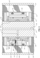
- motor 17 has a stator 27 that is fixed in a motor housing 29.
- Stator 27 may be conventional and is made up of a plurality of laminations, which are thin steel disks having slots through which windings (not shown) are inserted.
- Stator 27 has an inner diameter or bore 31.
- a shaft 33 extends through stator bore 31 along a longitudinal axis 35.
- Shaft 33 may have an axial passage 37 for distributing a dielectric lubricant.
- Several rotor sections 39 are mounted to shaft 33 for rotation therewith, and portions of two of the rotor sections 39 are shown.
- Each rotor section 39 may be conventional and is made up of laminations, which are also steel disks. Copper rods (not shown) extend axially through the rotor laminations and are spaced around axis 35. The rotor laminations and the ends of the copper rods are secured together by a copper end ring 41 at each end of each rotor section 39.
- An axially extending keyway 43 extends along the inner diameter of each rotor section 39 and on shaft 33 for receiving a key (not shown) to cause rotor sections 39 to rotate with shaft 33.
- Rotor sections 39 may be free to move small increments axially relative to shaft 33 in response to thermal growth.
- each rotor section 39 may be about 30cm (a foot) or so in length, and motor 17 may be up to 9 meters (30 feet) in length or more.
- a radial bearing 45 locates between each of the rotor sections 39 to radially stabilize shaft 33 during rotation.
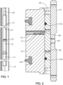
- Radial bearing 45 may have various configurations, and the one shown in Figure 2 includes a bearing sleeve 47 mounted to shaft 33 for rotation in unison. Bearing sleeve 47 is free to slide axially on shaft 33 a small increment.
- bearing sleeve 47 has one or more transverse lubricant ports 49 extending from its inner diameter to its outer diameter.
- Lubricant port 49 is in fluid communication with a shaft lubricant port 51. Lubricant flowing through shaft axial passage 37 flows through shaft and sleeve lubricant ports 49, 51 for lubricating radial bearing 45.
- a key 53 has radially outward extending fingers at its ends that engage notches or apertures in bearing sleeve 47 to cause bearing sleeve 47 to rotate with shaft 33.
- bearing sleeve 47 abuts end ring 41 of the next upward rotor section 39, and the lower end of bearing sleeve 47 abuts end ring 41 of the next lower rotor section 39.
- the terms "upper”, “lower” and the like are used only for convenience since motor 17 could be oriented horizontally during operation. Bearing sleeve 47 thus fixes the axial distance between end rings 41 of adjacent rotor sections 39.
- a non rotating cylindrical insert sleeve 55 surrounds and closely receives bearing sleeve 47.
- Insert sleeve 55 has two axially spaced apart rings 57a, 57b, which in this example are elastomeric seal rings, within annular grooves on its outer diameter.
- Lubricant ports 59 extend from the inner to the outer diameters of insert sleeve 55 to allow lubricant flow. Lubricant ports 59 are located axially between the two seal rings 57a, 57b.
- An annular carrier body 61 has a central bore or inner diameter that closely receives the outer diameter of insert sleeve 55 and is frictionally engaged by seal rings 57.
- Carrier body 61 has an outer diameter slightly smaller than stator bore 31.
- a pair of anti-rotation rings 63 are mounted in grooves on the outer diameter of carrier body 61. Anti-rotation rings 63 frictionally engage stator bore 31. Anti-rotation rings 63 may be elastomeric rings as shown, or coiled springs or other devices to prevent rotation of carrier body 61 relative to stator 27.
- Axial lubricant flow passages 65 are spaced in an array around carrier body 61 parallel with axis 35. Flow passages 65 extend between opposite ends of carrier body 61.
- Thrust washers 67 are located between the upper end of carrier body 61 and the end ring 41 of the next upward rotor section 39 as well as between the lower end of carrier body 61 and the end ring 41 of the next lower rotor section 39.
- the axial length of carrier body 61 is less than the axial length of bearing sleeve 47. Also, in this example, the axial length of carrier body 61 is greater than the axial length of insert sleeve 55. Retainer rings (not shown) may be employed in the inner diameter of carrier body 61 to keep insert sleeve 55 axially centered within carrier body 61.
- a hole 69 extends radially through carrier body 61.
- Hole 69 is cylindrical, has an outer end at the outer diameter of carrier body 61 and an inner end at the inner diameter of carrier body 61.
- a coil spring 71 is located within hole 69.
- Coil spring 71 is of a material, such as 302 stainless steel, that is electrically conductive and preferably either non- magnetic or has low magnetic characteristics.
- a retainer or roll pin 73 is secured within an outer portion of hole 69 on an outer end of coil spring 71.
- Roll pin 73 is conventional and also preferably formed of an electrically conductive material that has low or no magnetic characteristics.
- Roll pin 73 is cylindrical and may have an open passage through it.
- Roll pin 73 defines an inward facing shoulder against which an outer end of coil spring 71 contacts.
- An inner end of coil spring 71 protrudes out the inner end of hole 69 into contact with the outer diameter of insert sleeve 55.
- the length of coil spring 71 is greater than the distance from roll pin 73 to the outer diameter of insert sleeve 55, causing coil spring 71 to be compressed or biased by roll pin 73 against the outer diameter of insert sleeve 55.
- the frictional engagement of coil spring 71 with insert sleeve 55, roll pin 73, and carrier body 61 places insert sleeve 55 in electrical continuity with carrier body 61, which has a much larger mass than insert slee
- the inner end of hole 69 is closer to one of the ends of carrier body 61 than the other. In the example shown, the inner end of hole 69 is closer to the upper end than the lower end, but that arrangement could be reversed. Also, the inner end of hole 69 is axially between seal rings 57a, 57b. In this example, the inner end of hole 69 is closer to upper seal ring 57a than lower seal ring 57b. The inner end of hole 69 preferably does not register with any of the lubricant ports 59 in insert sleeve 55.
- a reason for positioning hole 69 closer to one end than the other of carrier body 61 has to do with a method of assembling bearing 45.
- the technician avoids sliding either seal ring 57a, 57b across the inner end of hole 59 while pushing insert sleeve 55 into carrier body 61.
- the technician installs lower seal ring 57b in its groove on insert sleeve 55 while the annular groove of upper seal ring 57a remains empty.
- the technician then pushes the upper end of insert sleeve 55 into the lower end carrier body 61 until the empty annular groove for upper seal ring 57a is exposed above the upper end of carrier body 61. In this position, lower seal ring 57b will be in the inner diameter of carrier body 61 just below hole 69.
- the technician then installs upper seal ring 57a in its annular groove and pushes insert sleeve 55 back downward to a final position with the axial center of insert sleeve 55 aligned with the axial center of carrier body 61.
- the technician then inserts coil spring 71 into the outer end of hole 69 and presses roll pin 73 in the outer portion of hole 69.
- stator 27 causes rotor sections 39, shaft 33 and bearing sleeve 47 to rotate.
- Seal rings 57a, 57b and anti-rotation rings 63 prevent insert sleeve 55 and carrier body 61 from rotating.
- Coil spring 71 maintains carrier body 61 and insert sleeve 55 in electrical continuity with each other. The continuity prevents a static electrical buildup from occurring on insert sleeve 55. A static electrical buildup could otherwise discharge to carrier body 61 and cause damage to seal rings 57a, 57b.
- the lubricant films created provide shock absorption to reduce vibration of shaft 33 from being transferred through insert sleeve 55 to carrier body 61 and stator 27.
- Insert sleeve ports 59 meter flow of lubricant between the inner and outer diameters of insert sleeve 55 as insert sleeve 55 moves slightly in radial directions relative to carrier body 61.
- the compliant engagement of coil spring 71 with insert sleeve 55 accommodates the slight radial vibrational movement of insert sleeve 55 relative to carrier body 61.
- the compliance of coil spring 71 prevents coil spring 71 from transmitting vibrations of insert sleeve 55 to carrier body 61.
- Anti-rotation rings 63 tend to prevent carrier body 61 and insert sleeve 55 from axially moving with bearing sleeve 47 and rotor sections 39. As a result, one of the thrust washers 67 may contact the nearby end ring 41 to absorb thrust from the rotating end ring 41. When motor 17 is shut down, the thermal growth reverses, and the other thrust washer 67 may contact the other end ring 41.
Landscapes
- Engineering & Computer Science (AREA)
- General Engineering & Computer Science (AREA)
- Mechanical Engineering (AREA)
- Power Engineering (AREA)
- Mining & Mineral Resources (AREA)
- Physics & Mathematics (AREA)
- Fluid Mechanics (AREA)
- Motor Or Generator Frames (AREA)
- Structures Of Non-Positive Displacement Pumps (AREA)
Claims (8)
- Moteur électrique (17) de pompe submersible, comprenant :un stator (27) présentant un alésage (31) ;un arbre (33) s'étendant à travers l'alésage le long d'un axe (35) du moteur ;des première et seconde sections de rotor (39) montées sur l'arbre pour une rotation avec celui-ci ;un manchon de palier (47) entre les première et seconde sections de rotor et monté sur l'arbre pour une rotation à l'unisson ;un manchon d'insert (55) ayant un diamètre interne qui reçoit le manchon de palier ;un corps de support (61) ayant un diamètre interne qui reçoit le manchon d'insert ;un élément antirotation de support (63) sur un diamètre externe du corps de support en prise avec l'alésage du stator, empêchant une rotation du corps de support par rapport au stator ;des première et seconde bagues d'étanchéité (57a, 57b) entre un diamètre externe du manchon d'insert et le diamètre interne du corps de support, empêchant une rotation du manchon d'insert par rapport au corps de support ; et caractérisé par :un trou (69) dans le corps de support (61) ayant une extrémité interne au niveau du diamètre interne du corps de support (61), l'extrémité interne du trou (69) étant située axialement entre les première et seconde bagues d'étanchéité (57a, 57b) ; etun ressort électroconducteur (71) dans le trou (69) et en prise avec le manchon d'insert (55) et avec le corps de support (61), créant une continuité électrique entre le manchon d'insert (55) et le corps de support (61).
- Moteur selon la revendication 1, dans lequel :
le ressort (71) comprend un élément enroulé sollicité en contact avec le diamètre externe du manchon d'insert (55). - Moteur selon la revendication 1 ou la revendication 2, dans lequel le trou (69) s'étend radialement dans le corps de support (61) ayant une ouverture au niveau du diamètre interne du corps de support ; et dans lequel
le ressort (71) a une extrémité externe à l'intérieur du trou (69) et une extrémité interne s'étendant à travers l'ouverture en contact avec le diamètre externe du manchon d'insert (55). - Moteur selon une quelconque revendication précédente, comprenant en outre :un épaulement tourné vers l'intérieur dans le trou (69) ; et dans lequelle ressort (71) a une extrémité externe en contact avec l'épaulement et une extrémité interne s'étendant à travers le trou (69) en contact avec le diamètre externe du manchon d'insert (55).
- Moteur selon une quelconque revendication précédente, dans lequel le trou (69) s'étend radialement du diamètre externe au diamètre interne du corps de support (61) ;le moteur comprenant en outre un élément de retenue amovible (73) fixé à l'intérieur d'une partie externe du trou (69) ; et dans lequelle ressort (71) comprend un élément enroulé sollicité entre le dispositif de retenue et le diamètre externe du manchon d'insert.
- Moteur selon la revendication 5, dans lequel le dispositif de retenue amovible (73) est une goupille cylindrique fixée par friction à l'intérieur de la partie externe du trou.
- Moteur selon une quelconque revendication précédente, dans lequel le trou (69) a une ouverture dans le diamètre interne du corps de support (61), l'ouverture étant plus proche d'une première extrémité du corps de support qu'une seconde extrémité du corps de support ; et dans lequel
le ressort (71) est monté dans le trou et sollicité en contact avec le diamètre externe du manchon d'insert. - Moteur selon une quelconque revendication précédente, dans lequel
le trou (69) a une extrémité externe au niveau du diamètre externe du corps de support (61), permettant que le ressort (71) soit introduit dans le trou (69) depuis l'extrémité externe du trou.
Applications Claiming Priority (2)
| Application Number | Priority Date | Filing Date | Title |
|---|---|---|---|
| US15/793,808 US10797555B2 (en) | 2017-10-25 | 2017-10-25 | Electrical discharge prevention in bearing for submersible pump motor using a conductive spring between a sleeve and a carrier body |
| PCT/US2018/052622 WO2019083666A1 (fr) | 2017-10-25 | 2018-09-25 | Prévention de décharge électrique dans un palier pour moteur de pompe submersible |
Publications (3)
| Publication Number | Publication Date |
|---|---|
| EP3701622A1 EP3701622A1 (fr) | 2020-09-02 |
| EP3701622A4 EP3701622A4 (fr) | 2021-07-28 |
| EP3701622B1 true EP3701622B1 (fr) | 2023-09-13 |
Family
ID=66169498
Family Applications (1)
| Application Number | Title | Priority Date | Filing Date |
|---|---|---|---|
| EP18869770.0A Active EP3701622B1 (fr) | 2017-10-25 | 2018-09-25 | Prévention de décharge électrique dans un palier pour moteur de pompe submersible |
Country Status (4)
| Country | Link |
|---|---|
| US (1) | US10797555B2 (fr) |
| EP (1) | EP3701622B1 (fr) |
| CA (1) | CA3080479C (fr) |
| WO (1) | WO2019083666A1 (fr) |
Families Citing this family (7)
| Publication number | Priority date | Publication date | Assignee | Title |
|---|---|---|---|---|
| US11088593B2 (en) | 2018-08-23 | 2021-08-10 | Baker Hughes Oilfield Operations Llc | Biased centralizing arms bearing in submersible pump motor |
| US11916450B2 (en) * | 2020-04-08 | 2024-02-27 | Halliburton Energy Services, Inc. | Axial flux submersible electric motor |
| WO2022212660A1 (fr) * | 2021-03-31 | 2022-10-06 | Schlumberger Technology Corporation | Conception de palier de rotor pour moteurs de fond de trou |
| FR3147058A1 (fr) * | 2023-03-24 | 2024-09-27 | Skf | Ensemble de brosse de mise à la terre |
| US12228171B2 (en) * | 2023-05-25 | 2025-02-18 | Halliburton Energy Services, Inc. | ESP motor radial bearing anti-rotation tab retention |
| FR3150656B1 (fr) * | 2023-06-30 | 2025-05-23 | Skf Svenska Kullagerfab Ab | Ensemble de brosse de mise à la terre |
| US12523131B2 (en) | 2024-06-25 | 2026-01-13 | Halliburton Energy Services, Inc. | Electric submersible pump with active cooling |
Family Cites Families (36)
| Publication number | Priority date | Publication date | Assignee | Title |
|---|---|---|---|---|
| US2747948A (en) * | 1954-11-12 | 1956-05-29 | John G Jergens | Pilot bearing |
| US4585963A (en) | 1982-11-01 | 1986-04-29 | Storage Technology Partners Ii | Brushless direct current motor with inverted magnet clip |
| DE3328362A1 (de) * | 1983-08-04 | 1985-02-21 | Siemens AG, 1000 Berlin und 8000 München | Flexible gedaempfte wellenlageranordnung, insbesondere fuer elektrische maschinen |
| US4521708A (en) * | 1984-03-15 | 1985-06-04 | Hughes Tool Company | Motor bearing with locking pins |
| US4621991A (en) * | 1985-02-22 | 1986-11-11 | Ametek, Inc. | Quiet by-pass vacuum motor |
| US5795075A (en) * | 1996-09-04 | 1998-08-18 | Camco International Inc. | Spring cartridge rotor bearing |
| US6091175A (en) * | 1998-03-12 | 2000-07-18 | Camco International, Inc. | Self-centering rotor bearing assembly for submersible pump motors |
| WO2000071903A1 (fr) | 1999-05-21 | 2000-11-30 | Sumitomo Electric Industries, Ltd. | Structure de palier, moteur d'entrainement, et unite de disque dur |
| US6300699B1 (en) | 1999-10-20 | 2001-10-09 | Baker Hughes Incorporated | Motor compensating spring |
| US6424066B1 (en) * | 1999-11-12 | 2002-07-23 | Camco International, Inc. | System for reducing wear and improving longevity of a electric submergible pumping system |
| US6956310B1 (en) * | 2000-09-07 | 2005-10-18 | Baker Hughes Incorporated | Motor bearing for submersible motors |
| US6566774B2 (en) | 2001-03-09 | 2003-05-20 | Baker Hughes Incorporated | Vibration damping system for ESP motor |
| DE20218821U1 (de) * | 2002-12-04 | 2003-03-20 | Minebea Co., Ltd., Meguro, Tokio | Spindelmotor mit elektrisch leitender Verbindung zwischen Lagersystem und Basisplatte bzw. Flansch |
| JP2004266985A (ja) | 2003-02-28 | 2004-09-24 | Hitachi Hybrid Network Co Ltd | 駆動源装置 |
| US8910718B2 (en) * | 2003-10-01 | 2014-12-16 | Schlumberger Technology Corporation | System and method for a combined submersible motor and protector |
| JP2006145002A (ja) | 2004-11-24 | 2006-06-08 | Yaskawa Electric Corp | モータ軸受およびそれを用いたモータ |
| US7625121B2 (en) * | 2005-09-28 | 2009-12-01 | Elliott Company | Bearing assembly and centering support structure therefor |
| US7808140B2 (en) * | 2007-08-07 | 2010-10-05 | Baker Hughes Incorporated | ESP motor design |
| US7950068B2 (en) | 2008-01-04 | 2011-05-31 | Fong Chang | Headwear comprising a bill which defines an enclosed space |
| US7780424B2 (en) | 2008-10-21 | 2010-08-24 | Baker Hughes Incorporated | Self leveling dynamically stable radial bearing |
| US8400035B2 (en) | 2008-12-27 | 2013-03-19 | Schlumberger Technology Corporation | Rotor bearing assembly |
| SG169286A1 (en) * | 2009-08-11 | 2011-03-30 | Baker Hughes Inc | Non-sliding carrier bearing in submersible pump motor and method of installation |
| US8342821B2 (en) * | 2010-10-21 | 2013-01-01 | Baker Hughes Incorporated | Tuned bearing |
| US8651836B2 (en) | 2011-04-08 | 2014-02-18 | Baker Hughes Incorporated | Torque transmitting rings for sleeves in electrical submersible pumps |
| JP5482723B2 (ja) | 2011-04-22 | 2014-05-07 | ダイキン工業株式会社 | 軸受け放電防止機構、及び電動機ユニット |
| US8987957B2 (en) * | 2013-01-16 | 2015-03-24 | Baker Hughes Incorporated | Systems and methods for facilitating oil flow in relation to rotor bearings |
| US20140205222A1 (en) * | 2013-01-24 | 2014-07-24 | Baker Hughes Incorporated | Systems and Methods for Preventing Electrical Arcing Between Components of Rotor Bearings |
| CN103321569A (zh) | 2013-06-25 | 2013-09-25 | 中国海洋石油总公司 | 凸轮式高频冲击钻井工具 |
| DE102013219186B4 (de) * | 2013-09-24 | 2022-11-24 | Vitesco Technologies GmbH | Elektrische Maschine und Verbindungseinheit für elektrische Maschine. |
| US9941770B2 (en) * | 2013-12-27 | 2018-04-10 | Baker Hughes, A Ge Company, Llc | Radial bearing thrust washer arrangement for submersible pump motor |
| US9325216B2 (en) | 2014-05-30 | 2016-04-26 | Summit Esp, Llc | Motor bearing for electric submersible motors |
| US9482282B2 (en) * | 2014-08-21 | 2016-11-01 | Zilift Holdings, Ltd. | Bearing for a rotary machine |
| DE102014115291A1 (de) | 2014-10-21 | 2016-05-12 | Ebm-Papst Mulfingen Gmbh & Co. Kg | Erdungsvorrichtung |
| US9790988B1 (en) * | 2014-12-08 | 2017-10-17 | Cadventures, Inc. | Self-adjusting bushing bearing having a springy element |
| US9951810B2 (en) * | 2016-01-20 | 2018-04-24 | Summit Esp, Llc | Electrical submersible motor radial support bearing |
| JP6666788B2 (ja) * | 2016-05-12 | 2020-03-18 | 株式会社ミクニ | 駆動装置およびポンプ装置 |
-
2017
- 2017-10-25 US US15/793,808 patent/US10797555B2/en active Active
-
2018
- 2018-09-25 WO PCT/US2018/052622 patent/WO2019083666A1/fr not_active Ceased
- 2018-09-25 EP EP18869770.0A patent/EP3701622B1/fr active Active
- 2018-09-25 CA CA3080479A patent/CA3080479C/fr active Active
Also Published As
| Publication number | Publication date |
|---|---|
| WO2019083666A1 (fr) | 2019-05-02 |
| CA3080479A1 (fr) | 2019-05-02 |
| BR112020008338A2 (pt) | 2020-10-20 |
| CA3080479C (fr) | 2020-12-22 |
| EP3701622A1 (fr) | 2020-09-02 |
| EP3701622A4 (fr) | 2021-07-28 |
| US20190123609A1 (en) | 2019-04-25 |
| US10797555B2 (en) | 2020-10-06 |
Similar Documents
| Publication | Publication Date | Title |
|---|---|---|
| EP3701622B1 (fr) | Prévention de décharge électrique dans un palier pour moteur de pompe submersible | |
| US10876534B2 (en) | Combined pump and motor with a stator forming a cavity which houses an impeller between upper and lower diffusers with the impeller having a circumferential magnet array extending upward and downward into diffuser annular clearances | |
| US8651836B2 (en) | Torque transmitting rings for sleeves in electrical submersible pumps | |
| US6091175A (en) | Self-centering rotor bearing assembly for submersible pump motors | |
| US10036389B2 (en) | Magnetic coupling unit for submersible well pumps | |
| US4521708A (en) | Motor bearing with locking pins | |
| EP3430266B1 (fr) | Section de rotor avec tube central pour moteur d'ensemble pompe submersible | |
| US9624938B2 (en) | Integrated motor bearing and rotor | |
| US8616863B2 (en) | ESP with offset laterally loaded bearings | |
| US9482282B2 (en) | Bearing for a rotary machine | |
| US9385570B2 (en) | Stator magnet wire end coil retention system | |
| EP3841305B1 (fr) | Palier de bras de centralisation sollicité dans un moteur de pompe immergée | |
| US11773702B2 (en) | Motor bearing with anti-rotation spring for electrical submersible well pump | |
| CA3165186C (fr) | Palier de moteur dote d'un ressort antirotation pour pompe electrique submersible de puits | |
| US20200340481A1 (en) | Permanent magnet pump with bearings separating modular sections | |
| BR112020008338B1 (pt) | Motor elétrico para bomba submergível |
Legal Events
| Date | Code | Title | Description |
|---|---|---|---|
| STAA | Information on the status of an ep patent application or granted ep patent |
Free format text: STATUS: THE INTERNATIONAL PUBLICATION HAS BEEN MADE |
|
| PUAI | Public reference made under article 153(3) epc to a published international application that has entered the european phase |
Free format text: ORIGINAL CODE: 0009012 |
|
| STAA | Information on the status of an ep patent application or granted ep patent |
Free format text: STATUS: REQUEST FOR EXAMINATION WAS MADE |
|
| 17P | Request for examination filed |
Effective date: 20200521 |
|
| AK | Designated contracting states |
Kind code of ref document: A1 Designated state(s): AL AT BE BG CH CY CZ DE DK EE ES FI FR GB GR HR HU IE IS IT LI LT LU LV MC MK MT NL NO PL PT RO RS SE SI SK SM TR |
|
| AX | Request for extension of the european patent |
Extension state: BA ME |
|
| DAV | Request for validation of the european patent (deleted) | ||
| DAX | Request for extension of the european patent (deleted) | ||
| REG | Reference to a national code |
Ref country code: DE Ref legal event code: R079 Free format text: PREVIOUS MAIN CLASS: H02K0011200000 Ipc: F04D0013100000 Ref country code: DE Ref legal event code: R079 Ref document number: 602018057684 Country of ref document: DE Free format text: PREVIOUS MAIN CLASS: H02K0011200000 Ipc: F04D0013100000 |
|
| A4 | Supplementary search report drawn up and despatched |
Effective date: 20210630 |
|
| RIC1 | Information provided on ipc code assigned before grant |
Ipc: F04D 13/10 20060101AFI20210624BHEP Ipc: F04D 29/047 20060101ALI20210624BHEP Ipc: F16C 17/02 20060101ALI20210624BHEP Ipc: H02K 5/132 20060101ALI20210624BHEP |
|
| GRAP | Despatch of communication of intention to grant a patent |
Free format text: ORIGINAL CODE: EPIDOSNIGR1 |
|
| STAA | Information on the status of an ep patent application or granted ep patent |
Free format text: STATUS: GRANT OF PATENT IS INTENDED |
|
| RAP3 | Party data changed (applicant data changed or rights of an application transferred) |
Owner name: BAKER HUGHES HOLDINGS LLC |
|
| INTG | Intention to grant announced |
Effective date: 20230530 |
|
| P01 | Opt-out of the competence of the unified patent court (upc) registered |
Effective date: 20230526 |
|
| GRAS | Grant fee paid |
Free format text: ORIGINAL CODE: EPIDOSNIGR3 |
|
| GRAA | (expected) grant |
Free format text: ORIGINAL CODE: 0009210 |
|
| STAA | Information on the status of an ep patent application or granted ep patent |
Free format text: STATUS: THE PATENT HAS BEEN GRANTED |
|
| AK | Designated contracting states |
Kind code of ref document: B1 Designated state(s): AL AT BE BG CH CY CZ DE DK EE ES FI FR GB GR HR HU IE IS IT LI LT LU LV MC MK MT NL NO PL PT RO RS SE SI SK SM TR |
|
| REG | Reference to a national code |
Ref country code: CH Ref legal event code: EP |
|
| REG | Reference to a national code |
Ref country code: DE Ref legal event code: R096 Ref document number: 602018057684 Country of ref document: DE |
|
| REG | Reference to a national code |
Ref country code: IE Ref legal event code: FG4D |
|
| REG | Reference to a national code |
Ref country code: NO Ref legal event code: T2 Effective date: 20230913 |
|
| REG | Reference to a national code |
Ref country code: LT Ref legal event code: MG9D |
|
| REG | Reference to a national code |
Ref country code: NL Ref legal event code: MP Effective date: 20230913 |
|
| PG25 | Lapsed in a contracting state [announced via postgrant information from national office to epo] |
Ref country code: GR Free format text: LAPSE BECAUSE OF FAILURE TO SUBMIT A TRANSLATION OF THE DESCRIPTION OR TO PAY THE FEE WITHIN THE PRESCRIBED TIME-LIMIT Effective date: 20231214 |
|
| PG25 | Lapsed in a contracting state [announced via postgrant information from national office to epo] |
Ref country code: SE Free format text: LAPSE BECAUSE OF FAILURE TO SUBMIT A TRANSLATION OF THE DESCRIPTION OR TO PAY THE FEE WITHIN THE PRESCRIBED TIME-LIMIT Effective date: 20230913 Ref country code: RS Free format text: LAPSE BECAUSE OF FAILURE TO SUBMIT A TRANSLATION OF THE DESCRIPTION OR TO PAY THE FEE WITHIN THE PRESCRIBED TIME-LIMIT Effective date: 20230913 Ref country code: LV Free format text: LAPSE BECAUSE OF FAILURE TO SUBMIT A TRANSLATION OF THE DESCRIPTION OR TO PAY THE FEE WITHIN THE PRESCRIBED TIME-LIMIT Effective date: 20230913 Ref country code: LT Free format text: LAPSE BECAUSE OF FAILURE TO SUBMIT A TRANSLATION OF THE DESCRIPTION OR TO PAY THE FEE WITHIN THE PRESCRIBED TIME-LIMIT Effective date: 20230913 Ref country code: HR Free format text: LAPSE BECAUSE OF FAILURE TO SUBMIT A TRANSLATION OF THE DESCRIPTION OR TO PAY THE FEE WITHIN THE PRESCRIBED TIME-LIMIT Effective date: 20230913 Ref country code: GR Free format text: LAPSE BECAUSE OF FAILURE TO SUBMIT A TRANSLATION OF THE DESCRIPTION OR TO PAY THE FEE WITHIN THE PRESCRIBED TIME-LIMIT Effective date: 20231214 Ref country code: FI Free format text: LAPSE BECAUSE OF FAILURE TO SUBMIT A TRANSLATION OF THE DESCRIPTION OR TO PAY THE FEE WITHIN THE PRESCRIBED TIME-LIMIT Effective date: 20230913 |
|
| REG | Reference to a national code |
Ref country code: AT Ref legal event code: MK05 Ref document number: 1611555 Country of ref document: AT Kind code of ref document: T Effective date: 20230913 |
|
| PG25 | Lapsed in a contracting state [announced via postgrant information from national office to epo] |
Ref country code: NL Free format text: LAPSE BECAUSE OF FAILURE TO SUBMIT A TRANSLATION OF THE DESCRIPTION OR TO PAY THE FEE WITHIN THE PRESCRIBED TIME-LIMIT Effective date: 20230913 |
|
| REG | Reference to a national code |
Ref country code: DE Ref legal event code: R119 Ref document number: 602018057684 Country of ref document: DE |
|
| PG25 | Lapsed in a contracting state [announced via postgrant information from national office to epo] |
Ref country code: IS Free format text: LAPSE BECAUSE OF FAILURE TO SUBMIT A TRANSLATION OF THE DESCRIPTION OR TO PAY THE FEE WITHIN THE PRESCRIBED TIME-LIMIT Effective date: 20240113 |
|
| PG25 | Lapsed in a contracting state [announced via postgrant information from national office to epo] |
Ref country code: AT Free format text: LAPSE BECAUSE OF FAILURE TO SUBMIT A TRANSLATION OF THE DESCRIPTION OR TO PAY THE FEE WITHIN THE PRESCRIBED TIME-LIMIT Effective date: 20230913 |
|
| PG25 | Lapsed in a contracting state [announced via postgrant information from national office to epo] |
Ref country code: ES Free format text: LAPSE BECAUSE OF FAILURE TO SUBMIT A TRANSLATION OF THE DESCRIPTION OR TO PAY THE FEE WITHIN THE PRESCRIBED TIME-LIMIT Effective date: 20230913 |
|
| PG25 | Lapsed in a contracting state [announced via postgrant information from national office to epo] |
Ref country code: SM Free format text: LAPSE BECAUSE OF FAILURE TO SUBMIT A TRANSLATION OF THE DESCRIPTION OR TO PAY THE FEE WITHIN THE PRESCRIBED TIME-LIMIT Effective date: 20230913 Ref country code: RO Free format text: LAPSE BECAUSE OF FAILURE TO SUBMIT A TRANSLATION OF THE DESCRIPTION OR TO PAY THE FEE WITHIN THE PRESCRIBED TIME-LIMIT Effective date: 20230913 Ref country code: IS Free format text: LAPSE BECAUSE OF FAILURE TO SUBMIT A TRANSLATION OF THE DESCRIPTION OR TO PAY THE FEE WITHIN THE PRESCRIBED TIME-LIMIT Effective date: 20240113 Ref country code: ES Free format text: LAPSE BECAUSE OF FAILURE TO SUBMIT A TRANSLATION OF THE DESCRIPTION OR TO PAY THE FEE WITHIN THE PRESCRIBED TIME-LIMIT Effective date: 20230913 Ref country code: EE Free format text: LAPSE BECAUSE OF FAILURE TO SUBMIT A TRANSLATION OF THE DESCRIPTION OR TO PAY THE FEE WITHIN THE PRESCRIBED TIME-LIMIT Effective date: 20230913 Ref country code: CZ Free format text: LAPSE BECAUSE OF FAILURE TO SUBMIT A TRANSLATION OF THE DESCRIPTION OR TO PAY THE FEE WITHIN THE PRESCRIBED TIME-LIMIT Effective date: 20230913 Ref country code: AT Free format text: LAPSE BECAUSE OF FAILURE TO SUBMIT A TRANSLATION OF THE DESCRIPTION OR TO PAY THE FEE WITHIN THE PRESCRIBED TIME-LIMIT Effective date: 20230913 Ref country code: SK Free format text: LAPSE BECAUSE OF FAILURE TO SUBMIT A TRANSLATION OF THE DESCRIPTION OR TO PAY THE FEE WITHIN THE PRESCRIBED TIME-LIMIT Effective date: 20230913 Ref country code: PT Free format text: LAPSE BECAUSE OF FAILURE TO SUBMIT A TRANSLATION OF THE DESCRIPTION OR TO PAY THE FEE WITHIN THE PRESCRIBED TIME-LIMIT Effective date: 20240115 |
|
| REG | Reference to a national code |
Ref country code: CH Ref legal event code: PL |
|
| PG25 | Lapsed in a contracting state [announced via postgrant information from national office to epo] |
Ref country code: LU Free format text: LAPSE BECAUSE OF NON-PAYMENT OF DUE FEES Effective date: 20230925 |
|
| REG | Reference to a national code |
Ref country code: BE Ref legal event code: MM Effective date: 20230930 |
|
| PG25 | Lapsed in a contracting state [announced via postgrant information from national office to epo] |
Ref country code: PL Free format text: LAPSE BECAUSE OF FAILURE TO SUBMIT A TRANSLATION OF THE DESCRIPTION OR TO PAY THE FEE WITHIN THE PRESCRIBED TIME-LIMIT Effective date: 20230913 Ref country code: LU Free format text: LAPSE BECAUSE OF NON-PAYMENT OF DUE FEES Effective date: 20230925 Ref country code: IT Free format text: LAPSE BECAUSE OF FAILURE TO SUBMIT A TRANSLATION OF THE DESCRIPTION OR TO PAY THE FEE WITHIN THE PRESCRIBED TIME-LIMIT Effective date: 20230913 |
|
| PG25 | Lapsed in a contracting state [announced via postgrant information from national office to epo] |
Ref country code: MC Free format text: LAPSE BECAUSE OF FAILURE TO SUBMIT A TRANSLATION OF THE DESCRIPTION OR TO PAY THE FEE WITHIN THE PRESCRIBED TIME-LIMIT Effective date: 20230913 |
|
| REG | Reference to a national code |
Ref country code: IE Ref legal event code: MM4A |
|
| PG25 | Lapsed in a contracting state [announced via postgrant information from national office to epo] |
Ref country code: IE Free format text: LAPSE BECAUSE OF NON-PAYMENT OF DUE FEES Effective date: 20230925 |
|
| PG25 | Lapsed in a contracting state [announced via postgrant information from national office to epo] |
Ref country code: DK Free format text: LAPSE BECAUSE OF FAILURE TO SUBMIT A TRANSLATION OF THE DESCRIPTION OR TO PAY THE FEE WITHIN THE PRESCRIBED TIME-LIMIT Effective date: 20230913 |
|
| PG25 | Lapsed in a contracting state [announced via postgrant information from national office to epo] |
Ref country code: CH Free format text: LAPSE BECAUSE OF NON-PAYMENT OF DUE FEES Effective date: 20230930 |
|
| PLBE | No opposition filed within time limit |
Free format text: ORIGINAL CODE: 0009261 |
|
| STAA | Information on the status of an ep patent application or granted ep patent |
Free format text: STATUS: NO OPPOSITION FILED WITHIN TIME LIMIT |
|
| PG25 | Lapsed in a contracting state [announced via postgrant information from national office to epo] |
Ref country code: MC Free format text: LAPSE BECAUSE OF FAILURE TO SUBMIT A TRANSLATION OF THE DESCRIPTION OR TO PAY THE FEE WITHIN THE PRESCRIBED TIME-LIMIT Effective date: 20230913 Ref country code: IE Free format text: LAPSE BECAUSE OF NON-PAYMENT OF DUE FEES Effective date: 20230925 Ref country code: DK Free format text: LAPSE BECAUSE OF FAILURE TO SUBMIT A TRANSLATION OF THE DESCRIPTION OR TO PAY THE FEE WITHIN THE PRESCRIBED TIME-LIMIT Effective date: 20230913 Ref country code: DE Free format text: LAPSE BECAUSE OF NON-PAYMENT OF DUE FEES Effective date: 20240403 Ref country code: CH Free format text: LAPSE BECAUSE OF NON-PAYMENT OF DUE FEES Effective date: 20230930 |
|
| 26N | No opposition filed |
Effective date: 20240614 |
|
| PG25 | Lapsed in a contracting state [announced via postgrant information from national office to epo] |
Ref country code: BE Free format text: LAPSE BECAUSE OF NON-PAYMENT OF DUE FEES Effective date: 20230930 |
|
| PG25 | Lapsed in a contracting state [announced via postgrant information from national office to epo] |
Ref country code: FR Free format text: LAPSE BECAUSE OF NON-PAYMENT OF DUE FEES Effective date: 20231113 |
|
| PG25 | Lapsed in a contracting state [announced via postgrant information from national office to epo] |
Ref country code: SI Free format text: LAPSE BECAUSE OF FAILURE TO SUBMIT A TRANSLATION OF THE DESCRIPTION OR TO PAY THE FEE WITHIN THE PRESCRIBED TIME-LIMIT Effective date: 20230913 |
|
| PG25 | Lapsed in a contracting state [announced via postgrant information from national office to epo] |
Ref country code: SI Free format text: LAPSE BECAUSE OF FAILURE TO SUBMIT A TRANSLATION OF THE DESCRIPTION OR TO PAY THE FEE WITHIN THE PRESCRIBED TIME-LIMIT Effective date: 20230913 Ref country code: FR Free format text: LAPSE BECAUSE OF NON-PAYMENT OF DUE FEES Effective date: 20231113 |
|
| PG25 | Lapsed in a contracting state [announced via postgrant information from national office to epo] |
Ref country code: BG Free format text: LAPSE BECAUSE OF FAILURE TO SUBMIT A TRANSLATION OF THE DESCRIPTION OR TO PAY THE FEE WITHIN THE PRESCRIBED TIME-LIMIT Effective date: 20230913 |
|
| PG25 | Lapsed in a contracting state [announced via postgrant information from national office to epo] |
Ref country code: BG Free format text: LAPSE BECAUSE OF FAILURE TO SUBMIT A TRANSLATION OF THE DESCRIPTION OR TO PAY THE FEE WITHIN THE PRESCRIBED TIME-LIMIT Effective date: 20230913 |
|
| PG25 | Lapsed in a contracting state [announced via postgrant information from national office to epo] |
Ref country code: CY Free format text: LAPSE BECAUSE OF FAILURE TO SUBMIT A TRANSLATION OF THE DESCRIPTION OR TO PAY THE FEE WITHIN THE PRESCRIBED TIME-LIMIT; INVALID AB INITIO Effective date: 20180925 |
|
| PG25 | Lapsed in a contracting state [announced via postgrant information from national office to epo] |
Ref country code: HU Free format text: LAPSE BECAUSE OF FAILURE TO SUBMIT A TRANSLATION OF THE DESCRIPTION OR TO PAY THE FEE WITHIN THE PRESCRIBED TIME-LIMIT; INVALID AB INITIO Effective date: 20180925 |
|
| PGFP | Annual fee paid to national office [announced via postgrant information from national office to epo] |
Ref country code: NO Payment date: 20250825 Year of fee payment: 8 |
|
| PGFP | Annual fee paid to national office [announced via postgrant information from national office to epo] |
Ref country code: GB Payment date: 20250820 Year of fee payment: 8 |
|
| PG25 | Lapsed in a contracting state [announced via postgrant information from national office to epo] |
Ref country code: TR Free format text: LAPSE BECAUSE OF FAILURE TO SUBMIT A TRANSLATION OF THE DESCRIPTION OR TO PAY THE FEE WITHIN THE PRESCRIBED TIME-LIMIT Effective date: 20230913 |