EP3701829B1 - Applicateur pour cheveux - Google Patents
Applicateur pour cheveux Download PDFInfo
- Publication number
- EP3701829B1 EP3701829B1 EP18870514.9A EP18870514A EP3701829B1 EP 3701829 B1 EP3701829 B1 EP 3701829B1 EP 18870514 A EP18870514 A EP 18870514A EP 3701829 B1 EP3701829 B1 EP 3701829B1
- Authority
- EP
- European Patent Office
- Prior art keywords
- comb
- hair
- applying part
- view
- barrel
- Prior art date
- Legal status (The legal status is an assumption and is not a legal conclusion. Google has not performed a legal analysis and makes no representation as to the accuracy of the status listed.)
- Active
Links
Images







Classifications
-
- A—HUMAN NECESSITIES
- A45—HAND OR TRAVELLING ARTICLES
- A45D—HAIRDRESSING OR SHAVING EQUIPMENT; EQUIPMENT FOR COSMETICS OR COSMETIC TREATMENTS, e.g. FOR MANICURING OR PEDICURING
- A45D34/00—Containers or accessories specially adapted for handling liquid toiletry or cosmetic substances, e.g. perfumes
- A45D34/04—Appliances specially adapted for applying liquid, e.g. using roller or ball
- A45D34/042—Appliances specially adapted for applying liquid, e.g. using roller or ball using a brush or the like
-
- A—HUMAN NECESSITIES
- A45—HAND OR TRAVELLING ARTICLES
- A45D—HAIRDRESSING OR SHAVING EQUIPMENT; EQUIPMENT FOR COSMETICS OR COSMETIC TREATMENTS, e.g. FOR MANICURING OR PEDICURING
- A45D19/00—Devices for washing the hair or the scalp; Similar devices for colouring the hair
- A45D19/02—Hand-actuated implements, e.g. hand-actuated spray heads
- A45D19/026—Hand-actuated implements, e.g. hand-actuated spray heads having brush or comb applicators
-
- A—HUMAN NECESSITIES
- A45—HAND OR TRAVELLING ARTICLES
- A45D—HAIRDRESSING OR SHAVING EQUIPMENT; EQUIPMENT FOR COSMETICS OR COSMETIC TREATMENTS, e.g. FOR MANICURING OR PEDICURING
- A45D24/00—Hair combs for care of the hair; Accessories therefor
- A45D24/22—Combs with dispensing devices for liquids, pastes or powders
-
- A—HUMAN NECESSITIES
- A45—HAND OR TRAVELLING ARTICLES
- A45D—HAIRDRESSING OR SHAVING EQUIPMENT; EQUIPMENT FOR COSMETICS OR COSMETIC TREATMENTS, e.g. FOR MANICURING OR PEDICURING
- A45D24/00—Hair combs for care of the hair; Accessories therefor
- A45D24/22—Combs with dispensing devices for liquids, pastes or powders
- A45D24/24—Combs with dispensing devices for liquids, pastes or powders with provision for free supply; using wicks
-
- A—HUMAN NECESSITIES
- A45—HAND OR TRAVELLING ARTICLES
- A45D—HAIRDRESSING OR SHAVING EQUIPMENT; EQUIPMENT FOR COSMETICS OR COSMETIC TREATMENTS, e.g. FOR MANICURING OR PEDICURING
- A45D24/00—Hair combs for care of the hair; Accessories therefor
- A45D24/22—Combs with dispensing devices for liquids, pastes or powders
- A45D24/26—Combs with dispensing devices for liquids, pastes or powders with flexible walls of the liquid, paste, or powder storing device
-
- A—HUMAN NECESSITIES
- A45—HAND OR TRAVELLING ARTICLES
- A45D—HAIRDRESSING OR SHAVING EQUIPMENT; EQUIPMENT FOR COSMETICS OR COSMETIC TREATMENTS, e.g. FOR MANICURING OR PEDICURING
- A45D2200/00—Details not otherwise provided for in A45D
- A45D2200/10—Details of applicators
- A45D2200/1009—Applicators comprising a pad, tissue, sponge, or the like
Definitions
- the present invention relates to a hair applicator for applying a hair cosmetic such as a hair dye, which is attached to a container body to apply an application liquid (hair dye, hair styling agent, hair restorer, etc.) stored in the container, to hair (hair including humans and other pet animals) while combing the hair.
- a hair cosmetic such as a hair dye
- an application liquid hair dye, hair styling agent, hair restorer, etc.
- Patent Documents 1 to 4 disclose hair applicators which have a structure including a combing body joined with an applying part of a porous material such as a sponge to apply and infiltrate the application liquid to the hair while combing with the combing body.
- Patent Documents 1 to 4 have the following problems.
- the combing body is fixed by provision of a bridge to prevent the porous applying part from falling off.
- the spacing between the comb elements is wide, the tips of the comb elements easily sink into the skin, so that the applying part easily touches and stains the skin. If a large clearance is secured between the combing body and the applying part in order to prevent the skin from being stained, there occurs a problem that the strength of contact of the applying part against the hair is weakened, so that the coating amount decreases.
- a non-infiltration member is integrally molded around the applying part (cosmetic penetrating member) to prevent the skin from being stained due to displacement of the applying part.
- the molding method is limited to extrusion molding, so that the manufacturing method and configuration lose flexibility.
- this method is easily expected to raise the costs required for, for example, the integral molding of the non-infiltration member and the grinding process after the integral molding.
- the present invention has been devised in view of the above circumstances, it is therefore an object of the present invention to provide a hair applicator which can fix an applying part to a comb with a sufficient fixing strength to prevent the applying part from being displaced even by an impact from a fall and also can dispense a sufficient coating amount.
- the present invention resides in a hair applicator according to claim 1.
- the applying part can be secured to the comb with a sufficient securing strength, so that it possible to prevent the applying part from being displaced even by an impact from a fall and obtain a sufficient coating amount.
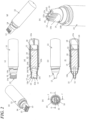
- FIGS. 1 to 6 are illustrative diagrams showing a hair applicator according to the first embodiment.
- the hair applicator includes an applying part 10 of a porous material and a comb 12 having comb elements 12a, formed with the applying part 10.
- the hair applicator is an applicator for hair that can dispense a hair dye in the front barrel (corresponding to the "container") 14 from the applying part 10 to the hair when the comb 12 combs the hair.
- the hair applicator has a cap 16 detachably attached to a front end part 14a of the front barrel 14 so as to cover the applying part 10.
- the cap 16 prevents the applying part 10 from drying by putting an inner cap 16a in hermetic contact with the outer peripheral side of the front end part 14a of the front barrel 14.
- the front barrel 14 has a substantially hollow cylindrical shape with the front end part 14a formed in a spatulate flat appearance having an opening forward of the hollow.
- the comb 12 is formed in the front end part 14a so as to surround the opening, and the applying part 10 is exposed from the opening.
- a tail plug (lid) 18 is fitted to the rear end of the front barrel 14 to close the hollow inside the front barrel 14 so as to provide a container function.
- an absorbent fabric 20 is stuffed in the closed space in the front barrel 14, and impregnated with the hair dye.
- the applying part 10 is arranged inside the comb 12 of the front barrel 14.
- the rear end of applying part 10 is inserted into the front portion of the absorbent fabric 20, so that the hair dye of the absorbent fabric 20 permeates the applying part 10.
- the front barrel 14 is covered from the center to the rear with a rear barrel 22.
- the rear barrel 22 has a cylindrical shape with a closed rear end, and a rib 22a for preventing rotation of the front barrel 14 is formed on the inner periphery along the axial direction.
- the rib 22a is formed as a projected portion such as a parallel rail.
- the front barrel 14 has a recess 14i formed along the axial direction on the outer surface in the rear portion thereof (see FIG. 3 ).
- the recess 14i of the front barrel 14 mates with the locking rib 22a to prevent the front barrel 14 from rotating with respect to the rear barrel 22.
- the front barrel 14 has a male thread 14b on the outer peripheral side of the front end part 14a for the cap 16 to be screwed thereon.
- a flange 14c is formed on the outer periphery adjacent to the rear of the male screw 14b.
- a fitting rib 14d is formed behind the flange 14c on the outer periphery.
- the rear barrel 22 has an annular projected portion 22b on the inner surface in the front part thereof.
- projected portions 14e are formed inside the front end part 14a of the front barrel 14 to catch a step portion 10c of the applying part.
- the applying part 10 is formed of a porous material having a porosity of 80% or higher and a hardness under ISO7619A of less than A70, which dispenses a coating amount of 0.090 g/m or greater
- the applying part 10 is given in the form of a flat plate having a greater width relative to the thickness.
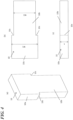
- the applying part 10 is formed of a front portion (applying tip side) 10a of a width W1 and a rear portion 10b of a width W2 smaller than W1, forming a substantially T-shape.
- the applying part 10 uses felt as the porous material in the embodiment.
- the dimensions of the applying part 10 are such that the thickness t is about 7 to 2 (mm), the width W1 of the front portion 10a is wider than the width W2 of the rear part 10b (W1> W2), and a step 10c is formed at the boundary between the front portion 10a and the rear portion 10b.
- the width W1 can be 15 to 10 (mm) and the width W2 can be 13 to 8 (mm).
- the length of the front portion 10a can be 15 to 10 (mm) and the length of the rear portion 10b can be 13 to 8 (mm) .
- the rear endface of the rear portion 10b contacts the absorbent fabric 20, but can be made flat.
- the front portion 10a of the width W1 serving as the applying tip is fitted inside of the front end part 14a. Further, the step 10c located at the boundary to the rear portion 10b of the width W2 is locked by the projected portions 14e formed in the front end part 14a of the front barrel 14. Therefore, this locking prevents the applying part 10 from sliding backward into the absorbent fabric 20 in the front barrel 14.
- a plurality of comb elements 12a extending forward are formed integrally with the front end part 14a of the front barrel 14.
- the front end part 14a has a rectangular opening, and holds the applying part 10 therein.
- the front end part 14a is configured such that the applying part 10 is held by the comb 12 on the front side with the tips of the comb elements 12a project forward beyond the front end of the applying part 10.
- beams 12b for anti-falling are formed so as to connect the opposing comb elements 12a.
- the step 10c abuts against the projected portions 14e inside the front barrel 14 (the front end part 14a) in the interior of the comb 12 to prevent the applying part 10 from moving rearward.
- the applying part 10 is made of a felt or the like that is softer than the applying part that is press-fitted in the conventional front barrel (Patent Document 1 and Patent Document 4), the applying part 10 is positioned and fixed on the front side by the beams 12b, and on the rear side by the projected portions 14e, so that the applying part 10 will not be displaced.
- the beam 12b between the comb elements 12a has a hollow 12b1 formed on the surface thereof. Further, the surface area of the tip of the comb element 12a is specified to be 0.3 to 1.0 mm 2 .
- the coating amount is 0.090 g/m or greater and the porous material has a porosity of 80% or higher and a hardness under ISO7619A of less than A70, the hardness is sufficient, so that it is possible to prevent the applying part from coming off from the front end part 14a of the front barrel 14.
- the applying part can be fixed to the comb elements with a sufficient fixing force, and prevented from being displaced even by an impact from a fall while an ample coating amount can be secured.
- the beams 12b are provided between the comb elements 12a of the front end part 14a, as described above. As shown in detail in FIGS. 2 and 5 , the beams 12b provide a stopper function for the applying part 10.
- an evaluation test was performed on the applying part 10 that was specified so that the coating amount was 0.090 g/m or greater and the porous material had a porosity of 80% or higher and a hardness under ISO7619A of less than A70.
- Example 1 the applying parts of Examples 1 and 2 of the present invention were felt cores, and the coating amount was 0.115 (g) in Example 1 and 0.104 (g) in Example 2.
- Comparative Examples 1 and 2 were felt cores, and the coating amount was 0.079 (g) in Comparative Example 1 and 0.069 (g) in Comparative Example 2.
- the porosity of each of Examples 1 and 2 and Comparative Examples 1 and 2 is an actual measurement value, which was obtained as the volume converted from the full filling weight of ethanol.
- the hardness is also an actual measurement value, which was obtained by using a rubber hardness meter (conforming to ISO7619A).
- each coating amount was 0.115 (g) in Example 1 and 0.104 (g) in Example 2, whereas the coating amount was 0.079 (g) in Comparative Example 1, and coating amount of Comparative Example 2 was 0.069 (g) .
- the applicators of Examples 1 and 2 have a coating amount of 10 to 12 times or more that of the applicators of Comparative Examples 1 and 2. Thus, according to the present invention, it has become clear that a markedly sufficient amount of coating (approximately an order of magnitude greater) can be applied to the hair.
- FIG. 5 shows a comparative example, and (b) shows a variational example 1.
- the comb 12 of the front barrel 14 has its front end located ahead of the applying part, if the front end of the comb 12 is formed flat as in the comparative example shown in FIG. 5(a) , the fluid may adhere to the skin.
- the cosmetic (application liquid) applied to the hair transfers to the flat top surface of the comb 12 and the top surface touches the skin so that the hair cosmetic is transferred to adhere to and stain the skin.
- the hollow 12b1 is formed on the front endface of the beam 12b of the comb 12 to reduce the contact area between the skin and the comb 12, so that transfer of the liquid can be avoided.
- FIG. 6 shows a comparative example, and (b) and (c) show the front barrel of the first embodiment.
- the cosmetic is more likely to adhere to the skin than in the conventional product. That is, as the comb elements 12a of the comb 12 are reduced in number, the contact area is reduced, hence it became easier to sink into the skin, and the applying part 10 easily comes into direct contact with the skin.
- the comb 12 in the comparative example shown in FIG. 6A has two pairs of comb elements 12a
- the comb 12 of the first embodiment shown in FIGS. 6B and 6C has five pairs of comb elements 12a so as to suppress sinking into the skin and make staining the skin unlikely.
- the beam 12b is provided in every other pair of the comb elements 12a among the five pairs in the comb 12, and hollows 12b1 are also formed.
- the area of the flat part in the front end of the comb part 12 was 0.4 mm 2
- the gap between the comb elements 12a was 1.3 mm.
- the step height of the hollow 12b1 in the preferred comb 12 was found to be 0.5 to 0.9 mm.
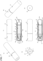
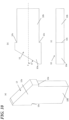
- FIGS. 7 to 10 are illustrative diagrams of a hair applicator according to a second embodiment
- FIG. 10 is an illustrative view of an applying part.
- the hair applicator according to the first embodiment is configured such that the comb elements 12a of the comb 12 are arranged and formed in the direction perpendicular to the center axis of the front barrel 14.
- the comb elements 12a of the comb 12 are arranged and formed in an inclined manner at an angle ⁇ with respect to the center axis of the front barrel 14 (indicated by the symbol "C" in FIG. 8 ).
- the applying part 10 is slanted forming a front part 10a of the facet inclined at the angle ⁇ with respect to the center axis (indicated by the symbol "C" in FIG. 10 ) .
- the applicator can be obliquely applied to the hair unlike the first embodiment in which the applicator is applied vertically. It is hence suitable for application to the hairline and the like. Others are the same as in the first embodiment.
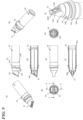
- FIGS. 11 and 12 are illustrative diagrams of the hair applicator according to the third embodiment.
- FIG. 13 is an illustrative diagram of a front barrel
- FIG. 14 is an illustrative diagram of an applying part.
- the same parts as those in the first embodiment shown in FIGS. 1 to 4 are denoted by the same reference numerals.
- the applying part 10 and the absorbent fabric 20 are the same as those in the first embodiment, and those in the second embodiment can also be adopted.
- the third embodiment is different from the first and second embodiments in the configurations other than the applying part 10 and the absorbent fabric 20.
- a container for accommodating the absorbent fabric 20 is formed with the rear end of the front barrel 14 closed by a tail plug 18.
- the tail plug 18 abuts the inner surface 22c (bottom surface) at the rear end of the rear barrel 22.
- the front part of the tail plug 18 serves as a part closing the rear end of the front barrel 14.
- the rear end of the tail plug 18 that is greater in diameter than the front end thereof serves as a part closing the rear end of the rear barrel 22.
- the hair applicator also has a cap 16 that covers the applying part 10 and the comb 12, as shown in FIG. 11 .
- the cap 16 can be fitted to a thread 14b on the front barrel (forming a container with the tail plug 18) 14 by a thread (female thread) 16b.
- the cap 16 and the front barrel 14 are formed with projections 16c (see FIG. 14 ) and 14f, which ride over each other into a fitted state.
- the front barrel 14 has a pair of projections 14f that allow the projections 16c (not shown) to ride over.
- Each projection 14f protrudes radially outward adjacent to the front side of the flange 14c.
- a rib 14g for stopping the rotation of the front barrel 14 relative to the rear barrel 22 is projectively formed on the rear side of the flange 14c.
- the projection 14f and the rib 14g are formed at the same position with respect to the circumferential direction of the front barrel 14.
- the rib 14g is formed as a projection on the inner surface of the front barrel so as to be engageable with a recess 22d to prevent the rear barrel 22 from rotating (see FIG. 12 ) .
- the rib 14g and the recess 22d can be appropriately provided in any form as long as they are engaged with each other.
- the front barrel 14 has the comb 12 in the front end part 14a.
- a groove 14h for air replacement is formed on the inner side surface of a comb element 12a in contact with the applying part 10. As shown in FIG. 13 , the groove 14h is formed in a portion facing one side surface of the applying part 10.
- the cap 16 has an inner cap 16a fitted and accommodated inside a main body forming an outer covering.
- ribs 16d for receiving the application liquid are formed radially on the inner surface of the inner cap.
- the projections 16c and 14f are formed on the cap 16 and the front barrel 14, respectively. Therefore, when the cap 16 is screw-fitted to the front barrel 14, the projections 16c ride over the projections 14f to create a clicking sensation when riding over.
- the user can make sure from the click feeling that the cap 16 and the front barrel 14 have been fitted when the cap 16 is closed. Also, once the projections 16c and 14f ride over, the projections again need to ride over each other when turning in the removal direction, so that unintentional removal can be prevented.
- the air replacement groove 14h is provided on the inner surface of the comb 12, air-liquid replacement can be smoothly performed in the applying part 10 and others. Thus, the air displacement from the applying part can be ensured, so that it is possible to prevent a supply shortage at the time of application.
- the tail plug 18 abuts the inner surface 22c (bottom surface) at the rear end of the rear barrel 22, to reliably prevent the tail plug 18 from falling off inside the rear barrel 22, thereby making it possible to prevent the absorbent fabric 20 from falling from the applying part 10.
- the hair applicator of the present invention can be used not only for human hair but also for animals.
Landscapes
- Cleaning And Drying Hair (AREA)
- Containers And Packaging Bodies Having A Special Means To Remove Contents (AREA)
Claims (5)
- Applicateur pour cheveux comprenant : une partie d'application (10) constituée d'un matériau poreux ; et un peigne (12) présentant plusieurs éléments de peigne (12a) fournis avec la partie d'application, pour appliquer par-là une couleur pour cheveux à partir d'un récipient (14) par l'intermédiaire de la partie d'application aux cheveux tout en peignant les cheveux avec le peigne,dans lequel les éléments de peigne supportent la partie d'application sur le côté avant de celle-ci, et les éléments de peigne font saillie vers l'avant à partir de la partie d'application, etdes poutres (12b) pour éviter que la partie d'application ne tombe vers l'avant sont formées dans le peigne afin de raccorder des éléments de peigne opposés,caractérisé en ce que le matériau poreux présente une porosité de 80 % ou supérieure et une dureté sous ISO7619A inférieure à A70, la quantité de revêtement par la partie d'application est de 0,090 g/m ou supérieure.
- Applicateur pour cheveux selon la revendication 1, dans lequel un creux est formé sur une surface de l'élément de peigne.
- Applicateur pour cheveux selon la revendication 1 ou 2, dans lequel la surface spécifique d'une face d'extrémité avant de l'élément de peigne est de 0,3 à 1,0 mm2.
- Applicateur pour cheveux selon l'une quelconque des revendications 1-3, comprenant de plus un bouchon (16) qui recouvre la partie d'application et le peigne, dans lequel le bouchon peut être fixé au récipient par un raccord à vis, et le bouchon et le récipient sont formés avec des saillies qui passent les unes sur les autres dans un état fixé.
- Applicateur pour cheveux selon l'une quelconque des revendications 1-4, dans lequel une rainure (14h) pour un remplacement d'air est formée sur une surface interne du peigne.
Applications Claiming Priority (2)
| Application Number | Priority Date | Filing Date | Title |
|---|---|---|---|
| JP2017206103 | 2017-10-25 | ||
| PCT/JP2018/039566 WO2019082944A1 (fr) | 2017-10-25 | 2018-10-24 | Applicateur pour cheveux |
Publications (3)
| Publication Number | Publication Date |
|---|---|
| EP3701829A1 EP3701829A1 (fr) | 2020-09-02 |
| EP3701829A4 EP3701829A4 (fr) | 2021-07-21 |
| EP3701829B1 true EP3701829B1 (fr) | 2023-08-16 |
Family
ID=66246487
Family Applications (1)
| Application Number | Title | Priority Date | Filing Date |
|---|---|---|---|
| EP18870514.9A Active EP3701829B1 (fr) | 2017-10-25 | 2018-10-24 | Applicateur pour cheveux |
Country Status (5)
| Country | Link |
|---|---|
| US (1) | US11641922B2 (fr) |
| EP (1) | EP3701829B1 (fr) |
| JP (1) | JP7281407B2 (fr) |
| CN (1) | CN111278325B (fr) |
| WO (1) | WO2019082944A1 (fr) |
Family Cites Families (18)
| Publication number | Priority date | Publication date | Assignee | Title |
|---|---|---|---|---|
| JPS5019700U (fr) * | 1973-06-22 | 1975-03-05 | ||
| US4376441A (en) * | 1980-10-14 | 1983-03-15 | Theodore Duncan | Hair treatment applicator |
| JP2899460B2 (ja) * | 1991-10-17 | 1999-06-02 | ユニチカ株式会社 | フェルトペン芯材料及びその製造法 |
| US5325878A (en) | 1992-07-17 | 1994-07-05 | Mckay William D | Fluid dispensing comb |
| JPH07223396A (ja) * | 1994-02-09 | 1995-08-22 | Unitika Ltd | フェルトペン芯材料及びその製造法 |
| FR2744104B1 (fr) * | 1996-01-29 | 1998-03-20 | Oreal | Dispositif de conditionnement, de distribution et d'application d'un gel ou mousse |
| JPH11169224A (ja) | 1997-12-11 | 1999-06-29 | Shiseido Co Ltd | 頭髪用塗布具 |
| FR2807295B1 (fr) | 2000-04-05 | 2002-10-18 | Oreal | Organe d'application pour l'application d'un produit sur un support et ensemble d'application ainsi equipe |
| JP2004154173A (ja) * | 2002-11-01 | 2004-06-03 | Mitsubishi Pencil Co Ltd | 液状化粧料塗布具 |
| JP4292881B2 (ja) * | 2003-06-11 | 2009-07-08 | 花王株式会社 | 櫛付キャップ |
| JP4726439B2 (ja) * | 2004-06-04 | 2011-07-20 | 三菱鉛筆株式会社 | 髪用塗布具及びその塗布具付き化粧料容器 |
| WO2006006378A1 (fr) * | 2004-07-08 | 2006-01-19 | Mitsubishi Pencil Co., Ltd. | Applicateur pour cheveux et conteneur cosmétique avec applicateur |
| DE102005044019A1 (de) | 2005-09-14 | 2007-03-22 | Georg Menshen Gmbh & Co. Kg | Vorrichtung zum Auftragen flüssiger Mittel auf das Kopfhaar |
| JP4971656B2 (ja) | 2006-03-28 | 2012-07-11 | シヤチハタ株式会社 | 頭髪用塗布具 |
| JP6406972B2 (ja) * | 2014-10-20 | 2018-10-17 | 三菱鉛筆株式会社 | 髪用塗布具 |
| JP2016087068A (ja) * | 2014-11-04 | 2016-05-23 | 三菱鉛筆株式会社 | 髪用塗布具 |
| JP2017104482A (ja) | 2015-04-14 | 2017-06-15 | 三菱鉛筆株式会社 | 髪用塗布具 |
| JP6654005B2 (ja) * | 2015-07-31 | 2020-02-26 | ホーユー株式会社 | 毛髪処理剤塗布具及び毛髪処理剤塗布具が取り付けられてなる毛髪処理具 |
-
2018
- 2018-10-24 US US16/758,441 patent/US11641922B2/en active Active
- 2018-10-24 WO PCT/JP2018/039566 patent/WO2019082944A1/fr not_active Ceased
- 2018-10-24 JP JP2019551216A patent/JP7281407B2/ja active Active
- 2018-10-24 EP EP18870514.9A patent/EP3701829B1/fr active Active
- 2018-10-24 CN CN201880069382.XA patent/CN111278325B/zh active Active
Also Published As
| Publication number | Publication date |
|---|---|
| JP7281407B2 (ja) | 2023-05-25 |
| WO2019082944A1 (fr) | 2019-05-02 |
| CN111278325A (zh) | 2020-06-12 |
| EP3701829A1 (fr) | 2020-09-02 |
| EP3701829A4 (fr) | 2021-07-21 |
| US11641922B2 (en) | 2023-05-09 |
| JPWO2019082944A1 (ja) | 2020-11-12 |
| CN111278325B (zh) | 2023-03-24 |
| US20200260830A1 (en) | 2020-08-20 |
Similar Documents
| Publication | Publication Date | Title |
|---|---|---|
| US7134799B2 (en) | Applicator including an applicator element for applying a substance, in particular a cosmetic or another care product | |
| US9668564B2 (en) | Cosmetic product applicator, device and associated method | |
| US7121284B2 (en) | Product applicator for eyelashes and/or eyebrows, and method of product application | |
| US9681725B2 (en) | Cosmetic product applicator, associated head and device | |
| EP3462976B1 (fr) | Applicateur cosmétique comportant des parties brosse et peigne moulées | |
| US6666607B2 (en) | Applicator and method for applying a product | |
| US20020174877A1 (en) | Devices and methods for applying a product to hair | |
| JP5258004B2 (ja) | 化粧料塗布具 | |
| JP5110467B2 (ja) | 櫛付きキャップ | |
| JP2018140018A (ja) | 化粧料塗布具 | |
| JP2004223266A (ja) | 物質、特に化粧品及び/またはケア製品を塗るアプリケータ要素を具備したアプリケータ、並びに、それを用いた装置及び方法 | |
| EP3701829B1 (fr) | Applicateur pour cheveux | |
| JP5718983B2 (ja) | 口唇化粧料塗布具 | |
| JP5716056B2 (ja) | 口唇化粧料塗布具 | |
| JP2010131329A (ja) | 口唇化粧料塗布具 | |
| JP6406972B2 (ja) | 髪用塗布具 | |
| JP5275664B2 (ja) | 塗布具 | |
| JP6532693B2 (ja) | 髪用塗布具 | |
| JP2006263233A (ja) | 液状化粧料容器 | |
| JP7170005B2 (ja) | 処理剤塗布具及び処理用製品 | |
| JPS628826Y2 (fr) | ||
| CN121712426A (zh) | 用于化妆品的涂抹器装置、涂抹此类产品的组件以及制造所述装置的方法 | |
| JP2021159288A (ja) | 液体化粧料容器のノーズピース | |
| JP2006345898A (ja) | 毛染め用具と容器の組合せ | |
| JP2019134983A (ja) | 髪用塗布具 |
Legal Events
| Date | Code | Title | Description |
|---|---|---|---|
| STAA | Information on the status of an ep patent application or granted ep patent |
Free format text: STATUS: THE INTERNATIONAL PUBLICATION HAS BEEN MADE |
|
| PUAI | Public reference made under article 153(3) epc to a published international application that has entered the european phase |
Free format text: ORIGINAL CODE: 0009012 |
|
| STAA | Information on the status of an ep patent application or granted ep patent |
Free format text: STATUS: REQUEST FOR EXAMINATION WAS MADE |
|
| 17P | Request for examination filed |
Effective date: 20200525 |
|
| AK | Designated contracting states |
Kind code of ref document: A1 Designated state(s): AL AT BE BG CH CY CZ DE DK EE ES FI FR GB GR HR HU IE IS IT LI LT LU LV MC MK MT NL NO PL PT RO RS SE SI SK SM TR |
|
| AX | Request for extension of the european patent |
Extension state: BA ME |
|
| DAV | Request for validation of the european patent (deleted) | ||
| DAX | Request for extension of the european patent (deleted) | ||
| A4 | Supplementary search report drawn up and despatched |
Effective date: 20210617 |
|
| RIC1 | Information provided on ipc code assigned before grant |
Ipc: A45D 19/02 20060101AFI20210611BHEP Ipc: A45D 24/22 20060101ALI20210611BHEP Ipc: A45D 24/24 20060101ALI20210611BHEP |
|
| GRAP | Despatch of communication of intention to grant a patent |
Free format text: ORIGINAL CODE: EPIDOSNIGR1 |
|
| STAA | Information on the status of an ep patent application or granted ep patent |
Free format text: STATUS: GRANT OF PATENT IS INTENDED |
|
| INTG | Intention to grant announced |
Effective date: 20230329 |
|
| P01 | Opt-out of the competence of the unified patent court (upc) registered |
Effective date: 20230523 |
|
| GRAS | Grant fee paid |
Free format text: ORIGINAL CODE: EPIDOSNIGR3 |
|
| GRAA | (expected) grant |
Free format text: ORIGINAL CODE: 0009210 |
|
| STAA | Information on the status of an ep patent application or granted ep patent |
Free format text: STATUS: THE PATENT HAS BEEN GRANTED |
|
| AK | Designated contracting states |
Kind code of ref document: B1 Designated state(s): AL AT BE BG CH CY CZ DE DK EE ES FI FR GB GR HR HU IE IS IT LI LT LU LV MC MK MT NL NO PL PT RO RS SE SI SK SM TR |
|
| REG | Reference to a national code |
Ref country code: CH Ref legal event code: EP |
|
| REG | Reference to a national code |
Ref country code: DE Ref legal event code: R096 Ref document number: 602018055675 Country of ref document: DE |
|
| REG | Reference to a national code |
Ref country code: IE Ref legal event code: FG4D |
|
| REG | Reference to a national code |
Ref country code: LT Ref legal event code: MG9D |
|
| REG | Reference to a national code |
Ref country code: NL Ref legal event code: MP Effective date: 20230816 |
|
| RAP4 | Party data changed (patent owner data changed or rights of a patent transferred) |
Owner name: MITSUBISHI PENCIL COMPANY, LIMITED |
|
| REG | Reference to a national code |
Ref country code: AT Ref legal event code: MK05 Ref document number: 1599131 Country of ref document: AT Kind code of ref document: T Effective date: 20230816 |
|
| PG25 | Lapsed in a contracting state [announced via postgrant information from national office to epo] |
Ref country code: GR Free format text: LAPSE BECAUSE OF FAILURE TO SUBMIT A TRANSLATION OF THE DESCRIPTION OR TO PAY THE FEE WITHIN THE PRESCRIBED TIME-LIMIT Effective date: 20231117 |
|
| PG25 | Lapsed in a contracting state [announced via postgrant information from national office to epo] |
Ref country code: IS Free format text: LAPSE BECAUSE OF FAILURE TO SUBMIT A TRANSLATION OF THE DESCRIPTION OR TO PAY THE FEE WITHIN THE PRESCRIBED TIME-LIMIT Effective date: 20231216 |
|
| PG25 | Lapsed in a contracting state [announced via postgrant information from national office to epo] |
Ref country code: SE Free format text: LAPSE BECAUSE OF FAILURE TO SUBMIT A TRANSLATION OF THE DESCRIPTION OR TO PAY THE FEE WITHIN THE PRESCRIBED TIME-LIMIT Effective date: 20230816 Ref country code: RS Free format text: LAPSE BECAUSE OF FAILURE TO SUBMIT A TRANSLATION OF THE DESCRIPTION OR TO PAY THE FEE WITHIN THE PRESCRIBED TIME-LIMIT Effective date: 20230816 Ref country code: PT Free format text: LAPSE BECAUSE OF FAILURE TO SUBMIT A TRANSLATION OF THE DESCRIPTION OR TO PAY THE FEE WITHIN THE PRESCRIBED TIME-LIMIT Effective date: 20231218 Ref country code: NO Free format text: LAPSE BECAUSE OF FAILURE TO SUBMIT A TRANSLATION OF THE DESCRIPTION OR TO PAY THE FEE WITHIN THE PRESCRIBED TIME-LIMIT Effective date: 20231116 Ref country code: NL Free format text: LAPSE BECAUSE OF FAILURE TO SUBMIT A TRANSLATION OF THE DESCRIPTION OR TO PAY THE FEE WITHIN THE PRESCRIBED TIME-LIMIT Effective date: 20230816 Ref country code: LV Free format text: LAPSE BECAUSE OF FAILURE TO SUBMIT A TRANSLATION OF THE DESCRIPTION OR TO PAY THE FEE WITHIN THE PRESCRIBED TIME-LIMIT Effective date: 20230816 Ref country code: LT Free format text: LAPSE BECAUSE OF FAILURE TO SUBMIT A TRANSLATION OF THE DESCRIPTION OR TO PAY THE FEE WITHIN THE PRESCRIBED TIME-LIMIT Effective date: 20230816 Ref country code: IS Free format text: LAPSE BECAUSE OF FAILURE TO SUBMIT A TRANSLATION OF THE DESCRIPTION OR TO PAY THE FEE WITHIN THE PRESCRIBED TIME-LIMIT Effective date: 20231216 Ref country code: HR Free format text: LAPSE BECAUSE OF FAILURE TO SUBMIT A TRANSLATION OF THE DESCRIPTION OR TO PAY THE FEE WITHIN THE PRESCRIBED TIME-LIMIT Effective date: 20230816 Ref country code: GR Free format text: LAPSE BECAUSE OF FAILURE TO SUBMIT A TRANSLATION OF THE DESCRIPTION OR TO PAY THE FEE WITHIN THE PRESCRIBED TIME-LIMIT Effective date: 20231117 Ref country code: FI Free format text: LAPSE BECAUSE OF FAILURE TO SUBMIT A TRANSLATION OF THE DESCRIPTION OR TO PAY THE FEE WITHIN THE PRESCRIBED TIME-LIMIT Effective date: 20230816 Ref country code: AT Free format text: LAPSE BECAUSE OF FAILURE TO SUBMIT A TRANSLATION OF THE DESCRIPTION OR TO PAY THE FEE WITHIN THE PRESCRIBED TIME-LIMIT Effective date: 20230816 |
|
| PG25 | Lapsed in a contracting state [announced via postgrant information from national office to epo] |
Ref country code: PL Free format text: LAPSE BECAUSE OF FAILURE TO SUBMIT A TRANSLATION OF THE DESCRIPTION OR TO PAY THE FEE WITHIN THE PRESCRIBED TIME-LIMIT Effective date: 20230816 |
|
| PG25 | Lapsed in a contracting state [announced via postgrant information from national office to epo] |
Ref country code: ES Free format text: LAPSE BECAUSE OF FAILURE TO SUBMIT A TRANSLATION OF THE DESCRIPTION OR TO PAY THE FEE WITHIN THE PRESCRIBED TIME-LIMIT Effective date: 20230816 |
|
| PG25 | Lapsed in a contracting state [announced via postgrant information from national office to epo] |
Ref country code: SM Free format text: LAPSE BECAUSE OF FAILURE TO SUBMIT A TRANSLATION OF THE DESCRIPTION OR TO PAY THE FEE WITHIN THE PRESCRIBED TIME-LIMIT Effective date: 20230816 Ref country code: RO Free format text: LAPSE BECAUSE OF FAILURE TO SUBMIT A TRANSLATION OF THE DESCRIPTION OR TO PAY THE FEE WITHIN THE PRESCRIBED TIME-LIMIT Effective date: 20230816 Ref country code: ES Free format text: LAPSE BECAUSE OF FAILURE TO SUBMIT A TRANSLATION OF THE DESCRIPTION OR TO PAY THE FEE WITHIN THE PRESCRIBED TIME-LIMIT Effective date: 20230816 Ref country code: EE Free format text: LAPSE BECAUSE OF FAILURE TO SUBMIT A TRANSLATION OF THE DESCRIPTION OR TO PAY THE FEE WITHIN THE PRESCRIBED TIME-LIMIT Effective date: 20230816 Ref country code: DK Free format text: LAPSE BECAUSE OF FAILURE TO SUBMIT A TRANSLATION OF THE DESCRIPTION OR TO PAY THE FEE WITHIN THE PRESCRIBED TIME-LIMIT Effective date: 20230816 Ref country code: CZ Free format text: LAPSE BECAUSE OF FAILURE TO SUBMIT A TRANSLATION OF THE DESCRIPTION OR TO PAY THE FEE WITHIN THE PRESCRIBED TIME-LIMIT Effective date: 20230816 Ref country code: SK Free format text: LAPSE BECAUSE OF FAILURE TO SUBMIT A TRANSLATION OF THE DESCRIPTION OR TO PAY THE FEE WITHIN THE PRESCRIBED TIME-LIMIT Effective date: 20230816 |
|
| REG | Reference to a national code |
Ref country code: DE Ref legal event code: R119 Ref document number: 602018055675 Country of ref document: DE |
|
| PG25 | Lapsed in a contracting state [announced via postgrant information from national office to epo] |
Ref country code: MC Free format text: LAPSE BECAUSE OF FAILURE TO SUBMIT A TRANSLATION OF THE DESCRIPTION OR TO PAY THE FEE WITHIN THE PRESCRIBED TIME-LIMIT Effective date: 20230816 |
|
| REG | Reference to a national code |
Ref country code: CH Ref legal event code: PL |
|
| REG | Reference to a national code |
Ref country code: BE Ref legal event code: MM Effective date: 20231031 |
|
| PG25 | Lapsed in a contracting state [announced via postgrant information from national office to epo] |
Ref country code: LU Free format text: LAPSE BECAUSE OF NON-PAYMENT OF DUE FEES Effective date: 20231024 |
|
| PLBE | No opposition filed within time limit |
Free format text: ORIGINAL CODE: 0009261 |
|
| STAA | Information on the status of an ep patent application or granted ep patent |
Free format text: STATUS: NO OPPOSITION FILED WITHIN TIME LIMIT |
|
| PG25 | Lapsed in a contracting state [announced via postgrant information from national office to epo] |
Ref country code: LU Free format text: LAPSE BECAUSE OF NON-PAYMENT OF DUE FEES Effective date: 20231024 |
|
| PG25 | Lapsed in a contracting state [announced via postgrant information from national office to epo] |
Ref country code: CH Free format text: LAPSE BECAUSE OF NON-PAYMENT OF DUE FEES Effective date: 20231031 |
|
| 26N | No opposition filed |
Effective date: 20240517 |
|
| GBPC | Gb: european patent ceased through non-payment of renewal fee |
Effective date: 20231116 |
|
| PG25 | Lapsed in a contracting state [announced via postgrant information from national office to epo] |
Ref country code: DE Free format text: LAPSE BECAUSE OF NON-PAYMENT OF DUE FEES Effective date: 20240501 Ref country code: CH Free format text: LAPSE BECAUSE OF NON-PAYMENT OF DUE FEES Effective date: 20231031 Ref country code: SI Free format text: LAPSE BECAUSE OF FAILURE TO SUBMIT A TRANSLATION OF THE DESCRIPTION OR TO PAY THE FEE WITHIN THE PRESCRIBED TIME-LIMIT Effective date: 20230816 |
|
| PG25 | Lapsed in a contracting state [announced via postgrant information from national office to epo] |
Ref country code: BE Free format text: LAPSE BECAUSE OF NON-PAYMENT OF DUE FEES Effective date: 20231031 |
|
| PG25 | Lapsed in a contracting state [announced via postgrant information from national office to epo] |
Ref country code: IE Free format text: LAPSE BECAUSE OF NON-PAYMENT OF DUE FEES Effective date: 20231024 |
|
| PG25 | Lapsed in a contracting state [announced via postgrant information from national office to epo] |
Ref country code: GB Free format text: LAPSE BECAUSE OF NON-PAYMENT OF DUE FEES Effective date: 20231116 |
|
| PGFP | Annual fee paid to national office [announced via postgrant information from national office to epo] |
Ref country code: FR Payment date: 20240909 Year of fee payment: 7 |
|
| PG25 | Lapsed in a contracting state [announced via postgrant information from national office to epo] |
Ref country code: IE Free format text: LAPSE BECAUSE OF NON-PAYMENT OF DUE FEES Effective date: 20231024 Ref country code: GB Free format text: LAPSE BECAUSE OF NON-PAYMENT OF DUE FEES Effective date: 20231116 |
|
| PG25 | Lapsed in a contracting state [announced via postgrant information from national office to epo] |
Ref country code: BG Free format text: LAPSE BECAUSE OF FAILURE TO SUBMIT A TRANSLATION OF THE DESCRIPTION OR TO PAY THE FEE WITHIN THE PRESCRIBED TIME-LIMIT Effective date: 20230816 |
|
| PG25 | Lapsed in a contracting state [announced via postgrant information from national office to epo] |
Ref country code: BG Free format text: LAPSE BECAUSE OF FAILURE TO SUBMIT A TRANSLATION OF THE DESCRIPTION OR TO PAY THE FEE WITHIN THE PRESCRIBED TIME-LIMIT Effective date: 20230816 |
|
| PG25 | Lapsed in a contracting state [announced via postgrant information from national office to epo] |
Ref country code: IT Free format text: LAPSE BECAUSE OF NON-PAYMENT OF DUE FEES Effective date: 20231024 |
|
| PG25 | Lapsed in a contracting state [announced via postgrant information from national office to epo] |
Ref country code: IT Free format text: LAPSE BECAUSE OF NON-PAYMENT OF DUE FEES Effective date: 20231024 |
|
| PG25 | Lapsed in a contracting state [announced via postgrant information from national office to epo] |
Ref country code: CY Free format text: LAPSE BECAUSE OF FAILURE TO SUBMIT A TRANSLATION OF THE DESCRIPTION OR TO PAY THE FEE WITHIN THE PRESCRIBED TIME-LIMIT; INVALID AB INITIO Effective date: 20181024 |
|
| PG25 | Lapsed in a contracting state [announced via postgrant information from national office to epo] |
Ref country code: HU Free format text: LAPSE BECAUSE OF FAILURE TO SUBMIT A TRANSLATION OF THE DESCRIPTION OR TO PAY THE FEE WITHIN THE PRESCRIBED TIME-LIMIT; INVALID AB INITIO Effective date: 20181024 |
|
| PG25 | Lapsed in a contracting state [announced via postgrant information from national office to epo] |
Ref country code: TR Free format text: LAPSE BECAUSE OF FAILURE TO SUBMIT A TRANSLATION OF THE DESCRIPTION OR TO PAY THE FEE WITHIN THE PRESCRIBED TIME-LIMIT Effective date: 20230816 |