EP3701836B1 - Dispositif de raccordement d'un élément avant à une partie latérale d'une partie de meuble mobile - Google Patents
Dispositif de raccordement d'un élément avant à une partie latérale d'une partie de meuble mobile Download PDFInfo
- Publication number
- EP3701836B1 EP3701836B1 EP20156645.2A EP20156645A EP3701836B1 EP 3701836 B1 EP3701836 B1 EP 3701836B1 EP 20156645 A EP20156645 A EP 20156645A EP 3701836 B1 EP3701836 B1 EP 3701836B1
- Authority
- EP
- European Patent Office
- Prior art keywords
- guide
- catch
- catch hook
- hook
- base body
- Prior art date
- Legal status (The legal status is an assumption and is not a legal conclusion. Google has not performed a legal analysis and makes no representation as to the accuracy of the status listed.)
- Active
Links
Images



Classifications
-
- A—HUMAN NECESSITIES
- A47—FURNITURE; DOMESTIC ARTICLES OR APPLIANCES; COFFEE MILLS; SPICE MILLS; SUCTION CLEANERS IN GENERAL
- A47B—TABLES; DESKS; OFFICE FURNITURE; CABINETS; DRAWERS; GENERAL DETAILS OF FURNITURE
- A47B88/00—Drawers for tables, cabinets or like furniture; Guides for drawers
- A47B88/90—Constructional details of drawers
- A47B88/944—Drawers characterised by the front panel
- A47B88/95—Drawers characterised by the front panel characterised by connection means for the front panel
- A47B88/956—Drawers characterised by the front panel characterised by connection means for the front panel for enabling adjustment of the front panel
-
- A—HUMAN NECESSITIES
- A47—FURNITURE; DOMESTIC ARTICLES OR APPLIANCES; COFFEE MILLS; SPICE MILLS; SUCTION CLEANERS IN GENERAL
- A47B—TABLES; DESKS; OFFICE FURNITURE; CABINETS; DRAWERS; GENERAL DETAILS OF FURNITURE
- A47B88/00—Drawers for tables, cabinets or like furniture; Guides for drawers
- A47B88/90—Constructional details of drawers
- A47B88/944—Drawers characterised by the front panel
- A47B88/95—Drawers characterised by the front panel characterised by connection means for the front panel
- A47B2088/954—Drawers characterised by the front panel characterised by connection means for the front panel fastening the front panel by a sprung bolt, latch or lock-bolt
-
- A—HUMAN NECESSITIES
- A47—FURNITURE; DOMESTIC ARTICLES OR APPLIANCES; COFFEE MILLS; SPICE MILLS; SUCTION CLEANERS IN GENERAL
- A47B—TABLES; DESKS; OFFICE FURNITURE; CABINETS; DRAWERS; GENERAL DETAILS OF FURNITURE
- A47B88/00—Drawers for tables, cabinets or like furniture; Guides for drawers
- A47B88/90—Constructional details of drawers
- A47B88/944—Drawers characterised by the front panel
- A47B88/95—Drawers characterised by the front panel characterised by connection means for the front panel
- A47B2088/955—Drawers characterised by the front panel characterised by connection means for the front panel fastening the front panel using a toggle-lever
Definitions
- the invention relates to a device for connecting a front element to a side part of a movable furniture part, in particular a drawer, with at least two fastening units lying one above the other in the vertical direction of the front element, of which an upper fastening unit has a holding projection with a holding section that can be fastened to the inside of the front element and, in the fastened state, projects from the inside in the direction of the side part, and a catching device for the holding projection that can be fastened to the side part, wherein the catching device has a base body and a catch hook that is movably loaded on the base body between a release position and a catch position, wherein the catch hook grips the holding section of the holding projection in the catch position, wherein the catching device has a slotted guide device and a manually drivable actuating device, by means of which the catch hook can be driven to perform a working movement composed of a clamping movement and a transverse movement superimposed thereon, wherein the catch hook can be moved by the clamping
- the US 10,010,174 B2 discloses a device for connecting a front element to a side part of a movable furniture part in the form of a drawer.
- a front panel is disclosed which, with its two fastening units and the holding projections formed there, is guided to a catch hook movably mounted on the side part of the drawer.
- the catch hook has two guide slots assigned to the respective holding projections on the front element. When retracted, the two holding projections on the front panel press the catch hook backwards until the back of the catch hook comes into contact with a stopper designed as an abutment.
- the front element also presses on a protruding drive element, so that the pressing element pivotally connected to the drive element presses with a pressing surface on the front of the catch hook and presses it straight with the help of a guide, with the two holding projections moving further into the assigned slots and reaching their respective end positions there.
- a connecting fitting which has a frame adapter which can be attached to a frame and on which a locking device is arranged.
- the locking device works together with a support device which in turn is attached to the front panel.
- the locking device has a base angle which is attached to the frame adapter and on which a locking lever 22 is pivotally mounted.
- the locking lever is spring-loaded and works together with a release lever which can be pivoted on the Base angle is mounted and is designed to be movable relative to the locking lever.
- the locking lever has a guide rail in the form of a curved slot into which a pin on the release lever is received such that the locking lever is held in an open position against the spring force of the spring.
- the pin on the release lever is assigned a guide track on the base angle.
- a pin is provided on the support device which strikes the release lever when it is retracted and presses the pin of the release lever held in the guide rail out of its holding position, whereby the spring force of the spring causes the locking lever to pivot towards the closed position, with the pin on the support device being gripped from behind by the locking lever.
- the object of the invention is to provide a device for connecting a front element to a side part of a movable furniture part, which is simple and cost-effective and, in particular, requires a smaller number of components compared to the previously described prior art.
- the device according to the invention is characterized in that the hook section is fork-shaped and has a U-shaped receiving fork, which is formed by two fork legs spaced parallel to one another and a fork yoke connecting the fork legs to one another, wherein the fork legs protrude upwards from the rest of the hook section and the receiving fork is open at the top.
- the catch hook can be moved from the release position to the clamping position by means of a simple manual actuation movement via the actuation device.
- the combined clamping and transverse movement easily ensures that the retaining projection associated with the front element is engaged behind and the front element is clamped to the side part.
- the fastening of the front to the side part is not dependent on the spring force of a spring. It should be noted that two fastening units arranged one above the other are provided, of which at least the upper fastening unit is equipped with a retaining projection and catch hook.
- the lower fastening unit has a latch associated with the front element, which moves into a latching receptacle arranged on the side part to fasten the front element.
- the link guide device has at least one guide unit with a guide track and a guide element assigned to the guide track, which slide off each other during the working movement, wherein the guide track is designed on the base body and the guide element is designed as a link follower on the catch hook.
- the guide track has a track section that runs diagonally upwards in the direction from the release position to the clamping position.
- the track section can be designed as an inclined plane. However, an arcuately curved track section is preferred.
- the track section that runs diagonally upwards can therefore ensure the transverse movement and thus in particular the engagement behind the holding projection by means of the catch hook.
- the guide track is formed by a wall section of a slot-like recess formed in the base body.
- the side part can be designed as a solid body.
- the side part can be made of wood, metal or plastic, for example.
- the base body can be designed as a sheet metal component, in particular a sheet metal component, expediently a sheet steel component.
- the base body can be attached to the side part as a separate component, for example detachably screwed there. Alternatively, however, it would also be conceivable for the base body to be connected in one piece with the rest of the side part.
- the link follower is designed as a guide pin that projects laterally from the catch hook in the direction of the base body.
- the link guide device has at least one guide unit with a guide track and a guide element assigned to the guide track, which slide against each other during the working movement, wherein the guide track is formed on the catch hook and the guide element is formed on the base body.
- the guide track on the catch hook is formed as an inclined surface of a section of the catch hook forming an inlet slope and the guide element is formed by a guide tab formed on the base body, which is equipped with a guide slot through which the section of the catch hook formed with the inclined surface passes with play in the vertical direction.
- the inclined surface extends upwards in the direction from the release position to the clamping position.
- two guide units are provided which are arranged one behind the other in the longitudinal direction of the catch hook.
- the second, in particular rear, guide unit is also expediently designed as a guide tab equipped with a guide slot.
- the catch hook according to the invention has a hook portion which, in the catch position, engages behind the holding portion of the holding projection and an elongated guide portion adjoining thereto in the longitudinal direction, in which at least one guide track or at least one guide element is or are formed.
- the guide section of the catch hook is designed like a sword.
- other elongated designs of the catch hook are also conceivable.
- a relatively thin-walled design of the guide section is certainly advantageous if a guide slot is passed through the guide tab.
- the hook section according to the invention is fork-shaped. It has a U-shaped receiving fork which is formed by two fork legs spaced parallel to one another and a fork yoke connecting the fork legs to one another, wherein the fork legs protrude upwards from the rest of the hook section and the receiving fork is open at the top.
- the retaining projection associated with the front element is designed as a retaining bolt, with a bolt shaft and a bolt head forming the retaining section and having a larger diameter than the bolt shaft.
- the actuating device has an actuating element which can be driven to perform a rotary movement, the rotary movement of which can be converted into the linear tensioning movement of the catch hook via conversion means belonging to the actuating device.
- the actuating device is designed as a worm drive, with an actuating element in the form of a worm wheel, on the front side of which an engagement contour for an engagement tool, for example a screwdriver, is formed, and on the back side of which a spiral-shaped link forming part of the transfer means is formed, which is connected to a toothing which is also part of the transfer means on the catch hook in such a way that the rotary movement of the actuating element can be converted into the clamping movement due to the eccentricity of the guide track.
- an engagement contour for an engagement tool for example a screwdriver
- the invention further comprises a furniture part, in particular a drawer, with a front element and two side parts, characterized by a device according to one of claims 1 to 11.
- the invention further comprises a piece of furniture with at least one furniture part, in particular a drawer, which has a front element and two side parts, characterized by a device according to one of claims 1 to 11.
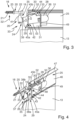
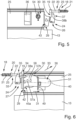
- FIGS. 1 to 6 show a first embodiment of the device 11 according to the invention, which serves to attach a front element 12 to a side part 13.
- the front element 12 is designed as a front panel.
- the front panel and the side part 13 are components of a drawer. Therefore, the front element 12 is to be attached to two opposite side parts 13, i.e. to a left and right side part 13.
- the Figures 2 to 6 The first embodiment of the device according to the invention shown can therefore also be present identically on the other second part in the example.
- the structure and the functioning of the device 11 described below therefore also apply in the same way to the other side part 13.
- the side part 13 can be designed as a drawer side wall that is attached to a guide rail of a guide unit that serves to guide the drawer.
- the drawer side wall can be a solid body made of wood, metal or plastic.
- the side part can also be designed as a drawer frame that accommodates components of the guide unit in the form of a hollow chamber frame.
- the device according to the invention is described below by way of example when using a side part designed as a hollow chamber frame.
- the hollow chamber frame can be designed as an extruded profile. Aluminum is a suitable extruded material. Alternatively, it is possible to manufacture the hollow chamber frame from sheet metal parts.
- the front element 12, in this example the front panel, can be made of wood, plastic or metal.
- the device 11 has at least two, in the example exactly two, fastening units 14a, 14b lying one above the other in the vertical direction of the front element 12 or side part 13.
- the lower fastening unit 14a is of less relevance in the following and is therefore only roughly described.
- the lower fastening unit has a latch 16 to be fastened to the inner side 15 of the front element 12, which can be moved into a latching receptacle formed on the frame in order to fasten the front element to the associated side part 13 in the form of the hollow chamber frame and is latched there.
- the upper fastening unit 14b has a holding projection 18 attached to the inner side 15 of the front element and protruding from the inner side 15 in the direction of the side part 13.
- the holding projection 18 has a holding section 19.
- the retaining projection 18 is designed as a retaining bolt, with a bolt shaft 20 and a bolt head forming the retaining section 19 and having a larger diameter than the bolt shaft 20.
- the bolt shaft 20 has a threaded section 21 for screwing into the front element 12.
- the threaded section 21 is designed in the manner of a self-tapping screw that can be screwed into a front panel made of wood.
- the threaded section 21 is followed by a threadless section 22.
- the threaded section 21 and the threadless section 22 are connected by a and the ring shoulder 23, which is larger in diameter than the threadless section 22.
- the ring shoulder 23 serves as a stop and specifies the screw-in depth of the threaded section 21.
- the bolt head is connected to the free end of the threadless section 22.
- the counterpart to the retaining projection 18 on the front element 12 is a catch device 24 for the retaining projection 18, which is attached to the side part 13, i.e. to the frame.
- the catch device 24 has a base body 25 and a catch hook 28 mounted on the base body 25 so as to be movable between a release position 26 and a catch position 27.
- the catch hook engages behind the holding section 19 of the retaining projection 18 in the catch position 27, as is particularly shown in Figure 6 shown.
- the catching device 24 has a slotted guide device 29 and a manually drivable actuating device 30, by means of which the catching hook 28 can be driven to a working movement 33 composed of a clamping movement 31 and a transverse movement 32 superimposed thereon, wherein the catching hook 28 can be moved by the clamping movement 31 between the release position 26 and a retracted clamping position 34 clamping the front element 12 to the side part 13, and wherein the slotted guide device 29 causes the transverse movement 32 of the catching hook 28 between the release position 26 and the catching position 27.
- the catch hook 28 has a hook section 35 which, in the catch position 27, engages behind the holding section 19, for example the bolt head, and an elongated guide section 36 adjoining it in the longitudinal direction.
- the guide section 36 is designed to be relatively thin-walled, for example in the manner of a sword.
- the catch hook is conveniently made entirely of sheet metal materials.
- Both the hook section 35 and the guide section 36 have several different functional sections.
- the hook portion 35 serves to engage behind the bolt head of the retaining projection 18 designed as a retaining bolt.
- the hook section 35 is fork-shaped and has a U-shaped receiving fork 37, which is formed by two fork legs 38a, 38b spaced parallel to one another and a fork yoke 39 connecting the fork legs to one another.
- the two fork legs 38a, 38b protrude upwards from the rest of the hook section 35 and end freely in the vertical direction.
- the U-shaped receiving fork 37 is therefore open at the top.
- the distance between the two fork legs 38a, 38b, which is formed transversely to the longitudinal axis 40 of the catch hook, is greater than the diameter of the unthreaded section 22 of the bolt shaft 20 of the retaining bolt.
- the distance between the two fork legs 38a, 38b is, however, smaller than the diameter of both the ring shoulder 23 and the retaining section 19 formed as a bolt head.
- the upwardly open receiving fork can therefore move with its two fork legs 38a, 38b to the left and right past the threadless section 22 if the catch hook is transferred from the release position to the catch position.
- the fork legs 38a, 38b each have an approximately triangular shape, with the shape of a right-angled triangle being preferred, with the hypotenuse forming an inclined surface 41 at the front end of the fork legs 38a, 38b.
- the inclined surface 41 is inclined in the direction of the guide section 36 of the catch hook.
- the link guide device 29 has at least one guide unit 42 with a guide track 43 and a guide element 44 assigned to the guide track 43, which slide against each other during the working movement.
- the guide track 43 is formed on the catch hook and the guide element 44 on the base body 25.
- the guide track 43 on the catch hook 28 is designed as an inclined surface 45 of a section of the catch hook 28 that forms an inlet slope.
- the guide section 36 which adjoins the hook section 35 in the axial direction, serves as the section of the catch hook 28.
- inclined surfaces 45a, 45b formed on mutually opposite longitudinal sections of the guide section 36 of the catch hook 28, of which either one or the other forms the guide track 43.
- the inclined surfaces 45a, 45b expediently have different slopes from one another.
- the guide track 43 i.e. one of the two inclined surfaces 45a, 45b, is assigned a guide element 44 on the base body 25.
- the base body 25 is in particular an integral component of the hollow chamber frame. However, it is also possible to design the base body as a separate component as a so-called frame attachment and to attach it to the hollow chamber frame, in particular in the area of its upper edge.
- the base body is conveniently made of sheet metal material that is relatively thin-walled.
- the base body 25 has a flat outer side 46 and an inner side opposite this, which is not shown in the figures.
- the base body 25 is expediently a bent sheet metal component in which the upper edge 47 running perpendicular to the outer side 46 is integrally connected to the outer side 46 and is created by bending an originally flat blank.
- the guide element 44 is formed by a guide tab formed in the base body.
- the guide tab is expediently also made from the flat blank of the base body or the hollow chamber frame by means of a bending process.
- the guide tab is equipped with a guide slot 48 through which the guide section 36 of the catch hook formed with the inclined surfaces 45a, 45b passes with play in the vertical direction.
- a further guide unit 49 is provided in the longitudinal direction of the catch hook 28, which also has a guide element in the form of a guide tab formed on the base body 25.
- the guide tab of the further guide unit 49 is expediently also formed from the material of the original blank of the base body 25 or the hollow chamber frame, for example by means of a window-like punching with a subsequent bending process inwards.
- the two guide tabs which are arranged one behind the other in the longitudinal direction of the catch hook 28, protrude essentially at right angles from the outside of the base body 25.
- the guide tab of the further guide unit 49 is equipped with a guide slot 50, through which an end section 51 of the guide section 36 of the catch hook passes.
- the device 11 comprises an actuating device 30 which has an actuating element 52 which can be driven to a rotary movement and whose rotary movement can be converted into the linear tensioning movement 31 of the catch hook 28 via conversion means 53 belonging to the actuating device 30.
- the actuating device is designed as a worm drive, with an actuating element 52 in the form of a worm wheel.
- the worm wheel is rotatably mounted on the base body 25 on its outer side 46.
- the worm gear has an engagement contour 54 on its front side for an engagement tool, for example a screwdriver.
- the engagement contour 54 is accessible from the outside 46 of the base body 25, in particular the engagement contour is flush with the outside 46.
- the engagement contour 54 is designed as a Phillips, Torx or Pozidriv engagement contour.
- On the back of the worm gear there is a spiral-shaped link 55 which forms part of the transfer means 53 and which interacts with a toothing 56 on the catch hook 28, which is also part of the transfer means 53, in such a way that the rotary movement of the actuating element 52 can be converted into the clamping movement due to the eccentricity of the link path.
- the toothing 56 has two teeth 57a, 57b lying one behind the other in the longitudinal direction of the guide section 36, which penetrate into the spiral-shaped guide 55.
- the lower fastening units are first fastened to one another by inserting the latch attached to the inside of the front element into the associated latching receptacle in the hollow chamber frame.
- the catch hook 28 of the catch device 24 is located in the Figure 3 and Figure 4 shown release position 26, thus extends diagonally downwards starting from the base body 25.
- the holding projection 18 fastened to the inner side 15 of the front panel is positioned such that the holding section 19 in the form of the bolt head is positioned between the hook section 35 and the front side of the base body 25.
- a rotary movement is initiated on the worm wheel via an engagement tool in the form of a screwdriver by inserting the screwdriver into the engagement contour and initiating a rotary movement.
- the rotary movement of the worm wheel caused by this causes a linear clamping movement 31 to the rear due to the eccentricity of the spiral-shaped link 55 and the teeth 57a, 57b engaging therein.
- the linear clamping movement is superimposed by a transverse movement 32 which begins when the inclined surface 45a, 45b slides along the frame of the associated guide slot 50, whereby the catch hook is moved upwards.
- the superposition of the linear, horizontal clamping movement 31 and the vertical transverse movement results in a working movement 33 obliquely backwards.
- the transverse movement initially causes the fork legs 38a, 38b to move past to the left and right of the threadless section 22 of the bolt shaft 20 and finally to engage behind the holding section 19 designed as a bolt head.
- the rotary movement initiated via the engagement tool is thus converted on the one hand into the clamping movement 31, which clamps the front element to the associated hollow chamber frame, and on the other hand into the transverse movement, whereby the catch hook 28 engages behind the holding section in the form of the bolt head and thus also secures the front element in the area of the upper fastening unit 14b to the associated hollow chamber frame.
- FIGS. 7 to 11 show a second embodiment of the device 11 according to the invention.
- the second embodiment differs from the previously described first embodiment by the different design of the link guide device 29.
- the slotted guide device 29 also has two guide units 42, 49 arranged one behind the other in the longitudinal direction of the catch hook 28, with a guide track 43 and a guide element 44 assigned to the guide track 43.
- the guide track 43 is located on the base body 25 and the guide element 44 is located as a slotted follower on the catch hook 28.
- the catch hook 28 has a hook section 35 which is constructed in a similar manner to the hook section 35 according to the first embodiment.
- a guide section 36 adjoins the hook section 35 in the longitudinal direction, on the outer side 46 of the base body 25
- Two link followers in the form of guide pins 58a, 58b are formed on the inner surface and are spaced axially apart from one another.
- the guide pins 58a, 58b protrude essentially at right angles from the inner side of the guide section 36 of the catch hook 28.
- the guide track 53 has a track section 63 running obliquely upwards in the direction from the release position 26 to the clamping position 34.
- the guide track 43 is formed by a wall section 59 of a slot-like recess 60 formed in the base body 25.
- the associated guide pin 58a, 58b thus rests on the band section 59 and can slide off it.
- the track section 63 running obliquely upwards is expediently curved in an arc shape.
- an actuating device 30 in the form of a worm drive is also provided, which can be designed in a similar or identical manner to the worm drive described above.
- the guide pin 58a slides along the inclined track section, which leads to a transverse movement superimposed on the linear horizontal tensioning movement, whereby the hook section 35 of the catch hook 28 is ultimately moved upwards, so that it engages behind the holding section 19 in the form of the bolt head in the manner described above.
Landscapes
- Connection Of Plates (AREA)
- Drawers Of Furniture (AREA)
Claims (13)
- Dispositif pour la liaison d'un élément de façade (12) à une partie latérale (13) d'une partie de meuble mobile, en particulier d'un tiroir, avec au moins deux unités de fixation (14a, 14b) situées l'une sur l'autre dans le sens de la hauteur de l'élément de façade (12), dont une unité de fixation supérieure (14b) présente une saillie de retenue (18) pouvant être fixée sur la face intérieure (15) de l'élément de façade (12) et dans l'état fixé en saillie à distance de la face intérieure (15) en direction de la partie latérale (13) avec une section de retenue (19) et un système d'arrêt (24) pour la saillie de retenue (18) pouvant être fixé sur la partie latérale (13), dans lequel le système d'arrêt (24) présente un corps de base (25) et un crochet d'arrêt (28) monté sur le corps de base (25) de manière mobile entre une position de libération (26) et une position d'arrêt (27), dans lequel le crochet d'arrêt (28) dans la position d'arrêt (27) vient se bloquer derrière la section de retenue (19) de la saillie de retenue (18), dans lequel le système d'arrêt (24) présente un système de guidage de coulisse (29) et un système d'actionnement (30) pouvant être entraîné manuellement, par lequel le crochet d'arrêt (28) peut être entraîné vers un mouvement de travail (33) se composant d'un mouvement de serrage (31) et d'un mouvement transversal (32) prioritaire par rapport à celui-ci, dans lequel le crochet d'arrêt (28) peut être déplacé par le mouvement de serrage (31) entre la position de libération (26) et une position de serrage (34) rentrée serrant l'élément de façade (12) sur la partie latérale (13), et dans lequel le système de guidage de coulisse (29) provoque le mouvement transversal (32) du crochet d'arrêt (28) entre la position de libération (26) et la position d'arrêt (27), et dans lequel le crochet d'arrêt (28) présente une section de crochet (35) venant se plaquer derrière la section de retenue (19) de la saillie de retenue (18) dans la position d'arrêt et une section de guidage (36) allongée se raccordant à celle-ci dans la direction longitudinale, sur laquelle au moins une bande de guidage (43) ou au moins un élément de guidage (44) est ou sont réalisé(e)s, caractérisé en ce
que la section de crochet (35) est réalisée en forme de fourche et présente une fourche de réception (37) en forme de U, qui est formée par deux branches de fourche (38a, 38b) espacées parallèlement l'une à l'autre et un joug de fourche (39) reliant les branches de fourche (38a, 38b) l'une à l'autre, dans lequel les branches de fourche (38a, 38b) font saillie du reste de la section de crochet (35) vers le haut et la fourche de réception (37) est ouverte vers le haut. - Dispositif selon la revendication 1, caractérisé en ce que le système de guidage de coulisse (29) présente au moins une unité de guidage (42, 49), avec la bande de guidage (43) et l'élément de guidage (44) associé à la bande de guidage (43), qui glissent l'un sur l'autre lors du mouvement de travail (33), dans lequel la bande de guidage (43) est réalisée sur le corps de base (25) et l'élément de guidage (44) en tant que suiveur de coulisse sur le crochet d'arrêt (28), dans lequel de préférence la bande de guidage (43) présente dans la direction à partir de la position de libération (26) vers la position de serrage (34) une section de bande (63) s'étendant de manière oblique vers le haut, dans lequel de préférence la section de bande (63) est réalisée de manière en forme d'arc.
- Dispositif selon la revendication 1 ou 2, caractérisé en ce que la bande de guidage (43) est formée par une section de paroi (59) d'un évidement (60) du type trou oblong réalisé dans le corps de base (25).
- Dispositif selon l'une quelconque des revendications précédentes, caractérisé en ce que le suiveur de coulisse est réalisé en tant que tige de guidage (58a, 58b) faisant saillie à distance du crochet d'arrêt (28) latéralement en direction du corps de base (25).
- Dispositif selon la revendication 1, caractérisé en ce que le système de guidage de coulisse (29) présente au moins une unité de guidage (42, 49), avec la bande de guidage (43) et l'élément de guidage (44) associé à la bande de guidage (43), qui glissent l'un sur l'autre lors du mouvement de travail (33), dans lequel la bande de guidage (43) est réalisée sur le crochet d'arrêt (28) et l'élément de guidage (44) sur le corps de base (25).
- Dispositif selon la revendication 5, caractérisé en ce que la bande de guidage (43) sur le crochet d'arrêt (28) est réalisée comme une surface inclinée (45a, 45b) d'une section du crochet d'arrêt (28) formant chanfrein d'entrée et l'élément de guidage (44) est formé par une languette de guidage réalisée sur le corps de base (25), qui est équipée d'une fente de guidage (48), qui est traversée par la section du crochet d'arrêt (28) réalisée avec la surface inclinée (45a, 45b) avec du jeu dans la direction verticale, dans lequel de préférence la surface inclinée (45a, 45b) s'étend vers le haut dans la direction à partir de la position de libération (26) dans la position de serrage (34).
- Dispositif selon la revendication 6, caractérisé en ce que deux surfaces inclinées (45a, 45b) réalisées sur les sections longitudinales opposées l'une à l'autre du crochet d'arrêt (28) sont présentes, dont soit l'une soit l'autre forme la bande de guidage (43), dans lequel de préférence les surfaces inclinées (45a, 45b) présentent des pentes différentes les unes des autres.
- Dispositif selon l'une quelconque des revendications précédentes, caractérisé par deux unités de guidage (42, 49) disposées l'une derrière l'autre dans la direction longitudinale du crochet d'arrêt (28).
- Dispositif selon l'une quelconque des revendications précédentes, caractérisé en ce que la saillie de retenue (18) associée à l'élément de façade (12) est réalisée en tant que boulon de retenue, avec une tige de boulon (20) et une tête de boulon formant la section de retenue présentant un plus grand diamètre par rapport à la tige de boulon (20).
- Dispositif selon l'une quelconque des revendications précédentes, caractérisé en ce que le système d'actionnement (30) présente un élément d'actionnement (52) à entraîner vers un mouvement rotatif, dont le mouvement rotatif peut être converti en mouvement de serrage (31) linéaire du crochet d'arrêt (28) par l'intermédiaire de moyens de conversion (53) faisant partie du système d'actionnement (30).
- Dispositif selon la revendication 10, caractérisé en ce que le système d'actionnement (30) est réalisé en tant qu'entraînement à vis sans fin, avec un élément d'actionnement (52) sous forme d'une roue à vis sans fin, sur la face avant de laquelle un contour d'insertion (54) pour un outil d'insertion, par exemple un tournevis, et sur la face arrière duquel une partie de la coulisse (55) en forme de spirale formant les moyens de conversion (53) est réalisée, qui coopère avec une denture (56) faisant également partie des moyens de conversion (53) sur le crochet d'arrêt (28), de telle sorte que le mouvement rotatif de l'élément d'actionnement (52) peut être converti en mouvement de serrage (31) en raison de l'excentricité du tracé de coulisse.
- Partie de meuble, en particulier tiroir, avec un élément de façade (12) et deux parties latérales (13), caractérisée par un dispositif selon l'une quelconque des revendications 1 à 11.
- Meuble, avec au moins une partie de meuble, en particulier tiroir, qui présente un élément de façade (12) et deux parties latérales (13), caractérisé par un dispositif selon l'une quelconque des revendications 1 à 11.
Applications Claiming Priority (1)
| Application Number | Priority Date | Filing Date | Title |
|---|---|---|---|
| DE202019101141.6U DE202019101141U1 (de) | 2019-02-28 | 2019-02-28 | Vorrichtung zur Verbindung eines Frontelements mit einem Seitenteil eines bewegbaren Möbelteils |
Publications (3)
| Publication Number | Publication Date |
|---|---|
| EP3701836A1 EP3701836A1 (fr) | 2020-09-02 |
| EP3701836B1 true EP3701836B1 (fr) | 2025-01-15 |
| EP3701836C0 EP3701836C0 (fr) | 2025-01-15 |
Family
ID=69571834
Family Applications (1)
| Application Number | Title | Priority Date | Filing Date |
|---|---|---|---|
| EP20156645.2A Active EP3701836B1 (fr) | 2019-02-28 | 2020-02-11 | Dispositif de raccordement d'un élément avant à une partie latérale d'une partie de meuble mobile |
Country Status (3)
| Country | Link |
|---|---|
| EP (1) | EP3701836B1 (fr) |
| DE (1) | DE202019101141U1 (fr) |
| ES (1) | ES3015174T3 (fr) |
Citations (1)
| Publication number | Priority date | Publication date | Assignee | Title |
|---|---|---|---|---|
| US10010174B2 (en) * | 2015-11-12 | 2018-07-03 | King Slide Works Co., Ltd. | Mounting mechanism |
Family Cites Families (8)
| Publication number | Priority date | Publication date | Assignee | Title |
|---|---|---|---|---|
| DE102010060722B4 (de) | 2010-11-22 | 2020-04-02 | Paul Hettich Gmbh & Co. Kg | Verbindungsbeschlag |
| DE102013106092B4 (de) * | 2013-06-12 | 2025-07-10 | Paul Hettich Gmbh & Co. Kg | Schubkasten mit Seitenzargen und einer justierbaren Frontblende |
| DE202014002229U1 (de) * | 2014-03-14 | 2014-04-29 | Erwin Krüger | Befestigungsbeschlag für eine Blende an einer offenen Stirnseite einer Schublade |
| DE102015105130A1 (de) * | 2015-04-02 | 2016-10-06 | Paul Hettich Gmbh & Co. Kg | Seitenzarge für einen Schubkasten und Verfahren zur Montage der Seitenzarge |
| DE102015122192B4 (de) * | 2015-12-18 | 2024-08-08 | Paul Hettich Gmbh & Co. Kg | Vorrichtung zum lösbaren Fixieren einer Frontblende und Verfahren zum Montieren und Demontieren einer Frontblende |
| CN106942922B (zh) * | 2017-03-23 | 2023-06-06 | 合肥乐卡智能五金制造有限公司 | 一种抽屉面板的固定装置 |
| WO2018208238A1 (fr) * | 2017-05-09 | 2018-11-15 | Samet Kalip Ve Madeni Esya San. Ve Tic. A.S. | Dispositif de retenue destiné à une façade de tiroir |
| US10799024B2 (en) * | 2017-05-09 | 2020-10-13 | Samet Kalip Ve Maden Esya San. Ve Tic. A.S. | Holding device for a front panel of a drawer |
-
2019
- 2019-02-28 DE DE202019101141.6U patent/DE202019101141U1/de active Active
-
2020
- 2020-02-11 ES ES20156645T patent/ES3015174T3/es active Active
- 2020-02-11 EP EP20156645.2A patent/EP3701836B1/fr active Active
Patent Citations (1)
| Publication number | Priority date | Publication date | Assignee | Title |
|---|---|---|---|---|
| US10010174B2 (en) * | 2015-11-12 | 2018-07-03 | King Slide Works Co., Ltd. | Mounting mechanism |
Also Published As
| Publication number | Publication date |
|---|---|
| EP3701836C0 (fr) | 2025-01-15 |
| DE202019101141U1 (de) | 2020-05-29 |
| EP3701836A1 (fr) | 2020-09-02 |
| ES3015174T3 (en) | 2025-04-29 |
Similar Documents
| Publication | Publication Date | Title |
|---|---|---|
| DE19963097C1 (de) | Zange zum Verpressen eines Werkstücks | |
| AT502487B1 (de) | Dämpferanordnung | |
| DE202013105469U1 (de) | Befestigungsanordnung, tragbares Arbeitsgerät zum Befestigen eines ersten Gehäuseteils an einem zweiten Gehäuseteil | |
| EP3593953B1 (fr) | Structure de support doté d'éléments porteurs pouvant être verrouillés sans cliquetis | |
| EP3565979B1 (fr) | Système de fixation et boîtier d'armoire de commande correspondant | |
| DE3038565C2 (de) | Heftapparat | |
| EP3010665B1 (fr) | Outil de pliage | |
| EP0755749A1 (fr) | Dispositif de guidage et/ou de fixation pour éléments, particulièrement pour éléments de fixation | |
| DE102009056099B4 (de) | Chirurgisches Instrument | |
| EP1245860B1 (fr) | Dispositif de fixation d'agrafes de jonction de courroie à des courroies transporteuses | |
| DE29816558U1 (de) | Zange | |
| EP3701836B1 (fr) | Dispositif de raccordement d'un élément avant à une partie latérale d'une partie de meuble mobile | |
| DE3131537A1 (de) | "eckverbindung" | |
| DE60103376T2 (de) | Biegevorrichtung, insbesondere für eine flache blechplatte | |
| DE4424493C2 (de) | Zangenartiges Werkzeug zum formschlüssigen Verbinden von Blechteilen | |
| DE3136879A1 (de) | Hebelspannzwinge | |
| DE10328309B4 (de) | Klappgelenk mit Innenverriegelung | |
| DE69901480T2 (de) | Automatischer korkenzieher | |
| DE2743322A1 (de) | Moebelscharnier | |
| DE29505752U1 (de) | Vorrichtung zum Verbinden von Platten mittels Verschraubung | |
| DE3909603C2 (fr) | ||
| EP3106265B1 (fr) | Outil portatif et son procede de fabrication | |
| EP3808217B1 (fr) | Dispositif pour relier un élément avant d'une partie mobile de meuble à un élément latéral de la partie mobile du meuble | |
| AT527376B1 (de) | Schubladenseitenwand für eine Schublade | |
| EP0485936A1 (fr) | Dispositif de serrure à barres avec joint des barres détachable |
Legal Events
| Date | Code | Title | Description |
|---|---|---|---|
| PUAI | Public reference made under article 153(3) epc to a published international application that has entered the european phase |
Free format text: ORIGINAL CODE: 0009012 |
|
| STAA | Information on the status of an ep patent application or granted ep patent |
Free format text: STATUS: THE APPLICATION HAS BEEN PUBLISHED |
|
| AK | Designated contracting states |
Kind code of ref document: A1 Designated state(s): AL AT BE BG CH CY CZ DE DK EE ES FI FR GB GR HR HU IE IS IT LI LT LU LV MC MK MT NL NO PL PT RO RS SE SI SK SM TR |
|
| AX | Request for extension of the european patent |
Extension state: BA ME |
|
| STAA | Information on the status of an ep patent application or granted ep patent |
Free format text: STATUS: REQUEST FOR EXAMINATION WAS MADE |
|
| 17P | Request for examination filed |
Effective date: 20210301 |
|
| RBV | Designated contracting states (corrected) |
Designated state(s): AL AT BE BG CH CY CZ DE DK EE ES FI FR GB GR HR HU IE IS IT LI LT LU LV MC MK MT NL NO PL PT RO RS SE SI SK SM TR |
|
| STAA | Information on the status of an ep patent application or granted ep patent |
Free format text: STATUS: EXAMINATION IS IN PROGRESS |
|
| 17Q | First examination report despatched |
Effective date: 20211129 |
|
| P01 | Opt-out of the competence of the unified patent court (upc) registered |
Effective date: 20230519 |
|
| GRAP | Despatch of communication of intention to grant a patent |
Free format text: ORIGINAL CODE: EPIDOSNIGR1 |
|
| STAA | Information on the status of an ep patent application or granted ep patent |
Free format text: STATUS: GRANT OF PATENT IS INTENDED |
|
| INTG | Intention to grant announced |
Effective date: 20240913 |
|
| GRAS | Grant fee paid |
Free format text: ORIGINAL CODE: EPIDOSNIGR3 |
|
| GRAA | (expected) grant |
Free format text: ORIGINAL CODE: 0009210 |
|
| STAA | Information on the status of an ep patent application or granted ep patent |
Free format text: STATUS: THE PATENT HAS BEEN GRANTED |
|
| AK | Designated contracting states |
Kind code of ref document: B1 Designated state(s): AL AT BE BG CH CY CZ DE DK EE ES FI FR GB GR HR HU IE IS IT LI LT LU LV MC MK MT NL NO PL PT RO RS SE SI SK SM TR |
|
| REG | Reference to a national code |
Ref country code: CH Ref legal event code: EP Ref country code: GB Ref legal event code: FG4D Free format text: NOT ENGLISH |
|
| REG | Reference to a national code |
Ref country code: DE Ref legal event code: R096 Ref document number: 502020010180 Country of ref document: DE |
|
| REG | Reference to a national code |
Ref country code: IE Ref legal event code: FG4D Free format text: LANGUAGE OF EP DOCUMENT: GERMAN |
|
| P04 | Withdrawal of opt-out of the competence of the unified patent court (upc) registered |
Free format text: CASE NUMBER: APP_6910/2025 Effective date: 20250210 |
|
| U01 | Request for unitary effect filed |
Effective date: 20250207 |
|
| U07 | Unitary effect registered |
Designated state(s): AT BE BG DE DK EE FI FR IT LT LU LV MT NL PT RO SE SI Effective date: 20250213 |
|
| U20 | Renewal fee for the european patent with unitary effect paid |
Year of fee payment: 6 Effective date: 20250226 |
|
| PGFP | Annual fee paid to national office [announced via postgrant information from national office to epo] |
Ref country code: ES Payment date: 20250306 Year of fee payment: 6 |
|
| REG | Reference to a national code |
Ref country code: ES Ref legal event code: FG2A Ref document number: 3015174 Country of ref document: ES Kind code of ref document: T3 Effective date: 20250429 |
|
| PG25 | Lapsed in a contracting state [announced via postgrant information from national office to epo] |
Ref country code: RS Free format text: LAPSE BECAUSE OF FAILURE TO SUBMIT A TRANSLATION OF THE DESCRIPTION OR TO PAY THE FEE WITHIN THE PRESCRIBED TIME-LIMIT Effective date: 20250415 |
|
| PG25 | Lapsed in a contracting state [announced via postgrant information from national office to epo] |
Ref country code: PL Free format text: LAPSE BECAUSE OF FAILURE TO SUBMIT A TRANSLATION OF THE DESCRIPTION OR TO PAY THE FEE WITHIN THE PRESCRIBED TIME-LIMIT Effective date: 20250115 |
|
| PG25 | Lapsed in a contracting state [announced via postgrant information from national office to epo] |
Ref country code: IS Free format text: LAPSE BECAUSE OF FAILURE TO SUBMIT A TRANSLATION OF THE DESCRIPTION OR TO PAY THE FEE WITHIN THE PRESCRIBED TIME-LIMIT Effective date: 20250515 Ref country code: NO Free format text: LAPSE BECAUSE OF FAILURE TO SUBMIT A TRANSLATION OF THE DESCRIPTION OR TO PAY THE FEE WITHIN THE PRESCRIBED TIME-LIMIT Effective date: 20250415 |
|
| PG25 | Lapsed in a contracting state [announced via postgrant information from national office to epo] |
Ref country code: HR Free format text: LAPSE BECAUSE OF FAILURE TO SUBMIT A TRANSLATION OF THE DESCRIPTION OR TO PAY THE FEE WITHIN THE PRESCRIBED TIME-LIMIT Effective date: 20250115 |
|
| PG25 | Lapsed in a contracting state [announced via postgrant information from national office to epo] |
Ref country code: GR Free format text: LAPSE BECAUSE OF FAILURE TO SUBMIT A TRANSLATION OF THE DESCRIPTION OR TO PAY THE FEE WITHIN THE PRESCRIBED TIME-LIMIT Effective date: 20250416 |
|
| REG | Reference to a national code |
Ref country code: CH Ref legal event code: PL |
|
| U1N | Appointed representative for the unitary patent procedure changed after the registration of the unitary effect |
Representative=s name: RAVENSPAT PATENTANWAELTE PARTNERSCHAFT MBB; DE |
|
| PG25 | Lapsed in a contracting state [announced via postgrant information from national office to epo] |
Ref country code: SM Free format text: LAPSE BECAUSE OF FAILURE TO SUBMIT A TRANSLATION OF THE DESCRIPTION OR TO PAY THE FEE WITHIN THE PRESCRIBED TIME-LIMIT Effective date: 20250115 |
|
| PG25 | Lapsed in a contracting state [announced via postgrant information from national office to epo] |
Ref country code: MC Free format text: LAPSE BECAUSE OF FAILURE TO SUBMIT A TRANSLATION OF THE DESCRIPTION OR TO PAY THE FEE WITHIN THE PRESCRIBED TIME-LIMIT Effective date: 20250115 |
|
| PG25 | Lapsed in a contracting state [announced via postgrant information from national office to epo] |
Ref country code: CH Free format text: LAPSE BECAUSE OF NON-PAYMENT OF DUE FEES Effective date: 20250228 |
|
| PG25 | Lapsed in a contracting state [announced via postgrant information from national office to epo] |
Ref country code: CZ Free format text: LAPSE BECAUSE OF FAILURE TO SUBMIT A TRANSLATION OF THE DESCRIPTION OR TO PAY THE FEE WITHIN THE PRESCRIBED TIME-LIMIT Effective date: 20250115 |
|
| PG25 | Lapsed in a contracting state [announced via postgrant information from national office to epo] |
Ref country code: SK Free format text: LAPSE BECAUSE OF FAILURE TO SUBMIT A TRANSLATION OF THE DESCRIPTION OR TO PAY THE FEE WITHIN THE PRESCRIBED TIME-LIMIT Effective date: 20250115 |
|
| PLBE | No opposition filed within time limit |
Free format text: ORIGINAL CODE: 0009261 |
|
| STAA | Information on the status of an ep patent application or granted ep patent |
Free format text: STATUS: NO OPPOSITION FILED WITHIN TIME LIMIT |
|
| 26N | No opposition filed |
Effective date: 20251016 |
|
| GBPC | Gb: european patent ceased through non-payment of renewal fee |
Effective date: 20250415 |
|
| PG25 | Lapsed in a contracting state [announced via postgrant information from national office to epo] |
Ref country code: GB Free format text: LAPSE BECAUSE OF NON-PAYMENT OF DUE FEES Effective date: 20250415 |
|
| PG25 | Lapsed in a contracting state [announced via postgrant information from national office to epo] |
Ref country code: IE Free format text: LAPSE BECAUSE OF NON-PAYMENT OF DUE FEES Effective date: 20250211 |
|
| U20 | Renewal fee for the european patent with unitary effect paid |
Year of fee payment: 7 Effective date: 20260225 |
|
| PGFP | Annual fee paid to national office [announced via postgrant information from national office to epo] |
Ref country code: TR Payment date: 20260204 Year of fee payment: 7 |