EP3701872B1 - Dispositif de détection de sons physiologiques - Google Patents
Dispositif de détection de sons physiologiques Download PDFInfo
- Publication number
- EP3701872B1 EP3701872B1 EP18869152.1A EP18869152A EP3701872B1 EP 3701872 B1 EP3701872 B1 EP 3701872B1 EP 18869152 A EP18869152 A EP 18869152A EP 3701872 B1 EP3701872 B1 EP 3701872B1
- Authority
- EP
- European Patent Office
- Prior art keywords
- conductive element
- sound
- thin film
- cavity
- detection device
- Prior art date
- Legal status (The legal status is an assumption and is not a legal conclusion. Google has not performed a legal analysis and makes no representation as to the accuracy of the status listed.)
- Active
Links
Images




Classifications
-
- A—HUMAN NECESSITIES
- A61—MEDICAL OR VETERINARY SCIENCE; HYGIENE
- A61B—DIAGNOSIS; SURGERY; IDENTIFICATION
- A61B7/00—Instruments for auscultation
- A61B7/02—Stethoscopes
- A61B7/04—Electric stethoscopes
-
- H—ELECTRICITY
- H04—ELECTRIC COMMUNICATION TECHNIQUE
- H04R—LOUDSPEAKERS, MICROPHONES, GRAMOPHONE PICK-UPS OR LIKE ACOUSTIC ELECTROMECHANICAL TRANSDUCERS; ELECTRIC HEARING AIDS; PUBLIC ADDRESS SYSTEMS
- H04R1/00—Details of transducers, loudspeakers or microphones
- H04R1/46—Special adaptations for use as contact microphones, e.g. on musical instrument, on stethoscope
Definitions
- the invention relates to the field of physiological information monitoring, in particular to a device for detecting physiological sounds.
- heart-related diseases such as high incidence of cardiovascular diseases
- the heart is the pump of a human body engine.
- the heart generates electrical simulation before mechanical contraction, produces a physical current which conducts onto the surface of a human body via tissue fluid and body fluid, so that different heart beat sounds are resulted in different parts to form a potential difference of different body surfaces.
- the heart problems can be prevented and monitored by means of recording and distinguishing the said real-time changes.
- ECG and heart sound measuring instrument To ensure accurate heart status monitoring of medical or scientific research significance, a ECG and heart sound measuring instrument is required. Although some small devices have been used for detecting heart sounds, which detects sounds and converts them into electronic signal for output, to achieve automatic detection of heart sounds, however, as the generation of heart or other physiological sounds involves very complicated processes and conditions, some pathological sounds are very difficult to distinguish from each other, it is necessary to carry out early detection, distinguish pathological sounds, and provide early treatment.
- JP 2014 090916 A discloses an acoustic sensor whose frequency region for sound collection can be efficiently adjusted, and whose sound collection sensitivity is high:
- the acoustic sensor includes: a cylindrical spacer; a diaphragm fitted to a spacer to close one side opening of the spacer; a back plate for closing the another side opening of the spacer; a vibrating electrode film provided on the back plate side surface of the diaphragm; a back electrode film provided on the diaphragm side surface of the back plate; and an electret film.
- the diaphragm is provided with a groove formed on the inner side than an inner surface of the cylindrical spacer to divide the diaphram into an inside area and an outside area.
- the electret film is formed on the back electrode film side surface of the vibrating electrode film and on the inner side than the groove.
- US 2007/165872 A1 describes a physiological sensing stethoscope suitable for use in high-noise environments.
- the stethoscope is designed to be substantially matched to the mechanical impedance of monitored physiological activity and substantially mismatched to the mechanical impedance of air-coupled acoustic activity.
- One embodiment of the stethoscope utilizes a passive acoustic system.
- Another embodiment utilizes an active Doppler system.
- the passive and active systems can be combined in one stethoscope enabling switching from a passive mode to an active mode suitable for use in very high-noise environments.
- the stethoscope is suitable for use in environments having an ambient background noise of 100 dBA and higher.
- the passive includes a head having a housing, a flexural disc mounted with the housing, and an electromechanical stack positioned between the housing and the flexural disc in contact with the skin of a patient.
- the active system detects Doppler shifts using a high-frequency transmitter and receiver.
- GB 2 051 584 A discloses a stethoscope having one or more resonant cavities adjusted to amplify sound frequencies of interest.
- the resonant cavities are preferably constituted by hollow tubes connected at one end to the main sound transmission passage and open to the atmosphere at the other end.
- the resonant cavities may be used in conjunction with a sound pick-up head comprising a cup-like structure having a diaphragm attached therewith and a probe for contacting a patient connected as part of the diaphragm; or the resonant cavities may be used in conjunction with a conventional sound pick-up head.
- US 2004/260193 A1 describes an apparatus and method for detecting infrasonic cardiac apical impulses of a patient including a sensor disposable in contact with skin of the patient for producing a signal responsive to a motion of the skin at an infrasonic cardiac apical impulse point of the patient.
- a first circuit coupled to the first sensor for generating at least one audible output in response to the first signal and indicative of the infrasonic cardiac apical impulse.
- US 1 015 163 A discloses a localizing-stethoscope.
- the flexible terminals of the tubes carrying the ear trumpet are connected to the transmitter body, which has connected to the threaded portions, the clamping ring of the transmitter body.
- the transmitter body is the main diaphragm held in proper adjustment at a central point by means of adjusting screws, while co-acting with the main diaphragm is a supplemental diaphragm provided with the concentric outwardly projecting cylindrical casing having the concaved outer face provided with the central orifice or aperture which is concentric with the periphery of the transmitter body.
- the invention overcomes the shortcomings of the prior art, and provides a new device for detecting physiological sounds which is characterized in simple and rational structure, low cost and high use value.
- a device for detecting physiological sounds according to claim 1.
- Optional features of the device are outlined in claims 2 to 15.
- concentrator head 1 bottom part 11, energy-collecting part 12, first cavity 100, first cavity 101, second cavity 102, second cavity 200, rigid material 201 and rigid material 202, resonant thin film 2, limiting part 21, thin film covering a conductive element 22, fixed part 3, thin film fixing part 31, joining part 32, ring edge 33, base 34, connecting hole 35, anti-slide structure 36, sensor 4; skin 5; apron structure 6.
- a thin film and conductive element A thin film and conductive element
- Stethoscope In traditional equipment for detecting physiological sounds, such as a stethoscope, when being used to hearing a physiological sound (a heart sound), making the thin film contact the skin surface, and then hearing the volume and change of a sound by ears.
- a physiological sound a heart sound
- Stethoscope is a very traditional equipment for hearing sounds and has a number of disadvantages though still used by many doctors.
- experienced talents can accurately distinguish a normal sound from a pathological sound, and judge the severity of a pathological sound.
- the equipment collects physiological sounds, converts the sounds into electric signals through a sensor, and then analyzes and filters the sound waves, recognizes the volume, change and occurrence time of the sound, judge whether the sound is normal, if the sound is not normal, a disease may occur.
- the China invention patent Patent No. 201310386451.9
- the heart sound (the sound of a heart) receives much concern. If the heart sound is abnormal, it often indicates that some functions of the heart cannot be performed properly, showing an early symptom of the heart which can be prevented in advance.
- the device can also detect the sound of other physiological organs, such as the sound of a lung or an intestine.
- the inventor of the present invention found that when a sound sensor is used to detect a physiological sound, if the conducted sound is collected first, the sound can be amplified with a physical method; the sound sensor can senses a stronger vibrations so as to identify a minor change of the sound and facilitate early diagnosis of a disease in an organ.
- the team of the invention accidentally found that adding a sound conductive element to the thin film of a traditional stethoscope can amplify a sound.
- the amplified sound is converted into an electronic signal through the sound sensor to allow digital detection of physiological sounds.
- a sound of a physiological organ is caused by the internal physiological changes of the organ, for example, the sound of a heart is closely related to the movement of the heart, and the movement of the heart is directly related to the generation of ECG.
- the following gives details, in particular to details of production and changes of a sound.
- the relaxation and contraction of the heart are accompanied by the flow of blood, and the flow of blood through the heart is accompanied by the production of the sound. This is called the heart sound.
- the invention additional provides a sound conductive element to a traditional stethoscope, which can amplify a physiological sound, and an electronic component is used to perform automatic recognition and calculation, automatic monitoring or diagnosis, so as to achieve automatic monitoring or diagnosis.
- the cavity comprises a thin film and the thin film is a part of the cavity, the cavity is a closed cavity and includes air inside, and the air can conduct a sound.
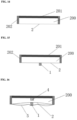
- the structure in FIG.1 the structure comprising an empty cavity 200, the cavity is surrounded by multiple surfaces, wherein a surface is provided with a thin film 2, and sound conductive element 1 is arranged on the thin film.
- the cavity 200 is a closed cavity, the so-called second cavity includes air inside, and the air can transmit a sound.
- the conductive element has a closed end 12 and an open end.
- the conductive element has a hollow structure, forming a first cavity 100.
- the first cavity 100 and the second cavity 200 form an integral sealed cavity.
- the combination of the thin film and the conductive element form a number of preferred embodiments, for example, making a small hole in the thin film 2, the size of the small hole being suitable for the opening at the other end of the conductive element, so as to enable the opening end of the conductive element to go through the small hole and then seal the gap between the thin film and the conductive element.
- the conductive element has a structure like a hat comprising a hat brim 11, or has an apron-like structure, the structure has a large surface, the surface can be used to bond with the thin film, so as to form the structure shown in FIG.1 .
- the thin film covering the opening of the conductive element may exist or not exist, if the thin film does not exist, it means that small holes exist in the location on the thin film that corresponds to the opening of the conductive element on the thin film.
- the material density of the conductive element is higher than the density of the thin film.
- the thin film that allows a sound to cause vibration is used, the thin film, such as some PVC, PCP or other similar films that can cause vibration, the vibration is caused by a sound.
- a thin film similar to the one used on a traditional stethoscope can also be used.
- the conductive element When detecting physiological sounds, making the closed end 12 of the conductive element to contact the skin of a living being, so as to detect the sound produced by the organ as the organ is underneath the skin.
- the conductive element protrudes relative to the thin film.
- the bump height may be 1mm, 2mm, 3mm, 4mm, 5mm, or 10mm.
- the device is used to detect a heart sound, making the closed end 12 contact the skin of a chest and the location of the heart is just beneath the skin of the chest.
- the biggest difference from a traditional stethoscope is that the stethoscope makes the whole thin film contact the skin, whereas the invention only makes the closed end of the conductive element 12 contact the skin.
- the area in contact with the skin is greatly reduced, we are surprised to find that the device can be used to amplify the physiological sound and have a more accurate detection. This will be described in details later. Therefore, in an embodiment, the area of a conductive element of the invention in contact with the surface or the skin is smaller than the area of a thin film.
- the heart sound detected above is an indirect sound. This is because the heart is located in the chest, The relaxation and contraction of the heart causes the flow of blood, and the flow of blood is from a large blood vessel into a heart ventricle and a heart atrium, and the heart ventricle and the heart atrium have valves, the valves close and open mechanically to control the flow of blood, this is bound to cause physiological sounds, and the sounds are transmitted to the surface of the skin through a subcutaneous tissue.
- the sound is transmitted in the form of waves, and this way of transmission can cause vibration, the transmission of the heart sound can cause vibration of the skin, making the thin film in contact with the skin is to transfer such vibration the thin film to cause the vibration of the thin film, so as to make the ears of a human hear or detect through a sound sensor the change of the heart sound.
- Making the whole thin film contact the skin or putting the conductive element in contact with the skin has substantial difference in transmission of a sound.
- the difference in effect may be caused by the following factors: on the one hand, the area of the thin film in contact with the skin is significantly larger than that of the conductive element. In this way, the reduced contact area only enables the conductive element to feel the vibration of a small area so that the disturbance on the vibration is minimized.
- This may be caused by transmission of the heart sound through the subcutaneous tissue, the subcutaneous tissue is heterogeneous, and the subcutaneous tissues have different densities, in this circumstance, when the sound is transmitted from the heart beneath the skin or to the skin surface, not all positions on the skin have the same vibration frequency; if making the thin film contact the skin at this moment, the thin film may have a different vibration frequency, if the thin film is made of the same material, the sound wave that causes the thin film frequency resonance is always at the same frequency, while sound waves of other frequencies may cause interference, this will allow the thin film to contact the skin in a large area to collect the possible frequencies of the sound, the so-called multi-frequency collection.
- vibrations of different frequencies exist on the thin film, and only a high vibration can be heard, because vibration can cause a second vibration of air, several different vibrations may cause vibrations in different parts of the air, but the vibration of air is messy, only if a sensor is used to receive the vibration of the thin film, the vibrations are still at variety of vibrations in different frequencies, thus to obtain messy sound waves with mixed frequencies; although the heart sound varies in high, medium and low frequencies, but for a sound wave with mixed vibration frequencies, the detection background may be enlarged, while the slight and weak sound might be ignored.
- the vibration on the thin film may not only include the single point vibration, the vibration of the air caused by the single point vibration is also of a single frequency; when a sensor is used to detect the sound wave, only the vibration of a single frequency is obtained, thus to reduce the interference from other frequencies.
- the single frequency does not mean only one frequency, it is a relative concept when the thin film contacts the skin in a large area. In this way, the point of the sound wave obtained by the sensor is specific, the sensitivity is increased and the weak sounds can be recognized.
- the area of the conductive element in contact with the skin can be 1/2, 1/3, 1/4, 1/5, 1/6, 1/7, 1/8, 1/9, 1/10, 1/12, 1/13, 1/15,1/20, 1/40, 1/50, 1/100 of the area of the thin film or any other proportion.
- Another important factor may be a volume change in a closed space.
- the volume of the closed space 200 formed on the thin film may not substantially changed, the air density of the closed cavity may not substantially changed, and the vibration of the thin film needs to be transmitted via air.
- the invention uses a conductive element, the conductive element, on one hand as mentioned above, has a reduced contact area with the skin.
- the conductive element and the skin have to bear a certain pressure, the pressure is generated by close contact between the conductive element and the skin, the vibration can be conducted to collect a stable sound wave.
- the conductive element when the conductive element closely contacts the skin, the conductive element surely impose a reserve force on the thin film to make the thin film move inward, thus to reduce the volume of the closed space, the reduction of the volume can lead to reduction of the air volume, relative to the initial status of the thin film, the air is compressed, and the density is increase after air compression. Sound waves can be transmitted through air, while the volume of air decreases and the density increases, thereby increasing the effect of sound wave transmission. If the sound sensor is placed in a sealed space, the current signal sensed can be significantly enhanced. Therefore, another essential characteristic of the present invention is that the volume of the second closed space is reduced when the conductive element is in contact with the surface of a living being.
- a device for detecting sounds comprises a closed space, the closed space is provided with a thin film surface, When the thin film contacts with the surface of a living being to test the sound of the organs of the living being, the volume of the closed space decreases, thereby compressing the air in the closed space.
- the compression can be, for example, the above compression with a conductive element, or a compression by another method, if the volume of the closed space formed by the thin film is reduced when the thin film is sensing or transmitting sound waves, the density of the air can be increased.
- the case can also be that the volume of the closed space remains unchanged, but the density of the air increases, for example injecting more air from another position, so as to increase the density of the air per unit volume.
- the so-called closed space refers to the closed state of the space during detecting or preparing for detection.
- the space is a closed state.
- the air or gas content in the space is substantially determined, but the volume of the closed space can be changed, for example, reduction of the volume. Either increasing of air in the closed space or increasing of air density can achieve the effect of relatively enlarging the sound of the invention.
- the thin film is elastic, the volume of the above closed space is reduced. If the thin film is not an elastic film, before or during detecting, inflating air in the space can increase the density of the gas molecules.
- the space is non-closed, during detecting or preparing for a detection, an open end of the conductive element 150 is put in contact with the skin surface of a human or a mammal, to form a closed space, the thin film 2 and the conductive element can still conduct sounds.
- the closed space is mainly formed by rigid materials, while the thin film 2 has certain elasticity.
- the volume of the closed space can not be compressed; the compression may be very small and can be ignored even if there is.
- a raised conductive element 1 is arranged on the thin film 2, the conductive element 1 has rigidness as compared with the thin film 2, because the conductive element has a small bump and the bump can not cause elastic deformation, but for the thin film, it can cause deformation of the thin film, and lead to vibration, thereby obtaining a sound wave or a sound of a certain frequency.
- one end of the conductive element 1 contacts the skin 5, general the element should closely contact the skin, so as to apply a pressure to the conductive element, and the pressure can be applied to the skin contacted during the detection, and indirectly applied through other rigid material 201 or 202 of the closed space.
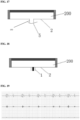
- the conductive element Due to the elasticity of the thin film, the conductive element reacts on the thin film, the skin is under the pressure applied by the conductive element, and the conductive element also applies a pressure to the thin film, then the pressure causes the thin film to press into the closed space, so as to reduce the volume of the closed space but the air content in the closed space remains; when the volume is small, the density of air molecules can increase, the sound conducted from the conductive element 1 causes vibration of air molecules in the closed space, thereby achieving transmission of sounds (as shown in FIG.16 ).
- the closed space is provided with a sound sensor 4 to sense a sound transmitted by air.
- the sound is converted to an electrical signal for further analysis, for example, filtering, division of high, low and medium frequencies, and analyzing the high, low and medium frequencies.
- the air above mentioned can also be replaced by other gas molecules, such as a single gas molecule, a carbon dioxide molecule, a nitrogen molecule, an oxygen molecule; while air is preferred.
- a first cavity 100 is arranged on the conductive element, when the thin film deforms and presses into the closed space, the first cavity 100 corresponds to a sensor, a part of the sensor can enter the first cavity 100 but not contact with the thin film and the conductive element, so as to save space and better sense or sense the changes in the sound more closely, thereby guaranteeing more sensitive detection.
- sound is a pressure wave; when playing a musical instrument, taping on a door or knocking a table, the sound vibrations cause, the medium- air molecules, to vibrate rhythmically, cause change in the density of the surrounding air, producing an alternating longitudinal wave, thus a sound wave is created, and such phenomenon continues until the vibrations disappear.
- sound can always be decomposed into superposition of sine waves of different frequencies and intensities.
- the process of transformation (or decomposition) is called the Fourier Transform.
- a general sound always includes a certain frequency range.
- a human ear can hear the sounds in a frequency range of 20 to 20,000 HZ.
- the waves below the range are called ultrasonic waves, and the waves below the range are called infrasonic waves.
- the speed at which a sound travels is related to the counterbalancing force of the medium, counterbalancing force means when a molecule of a matter deviates from its equilibrium position, the surrounding molecules push the molecule back to the equilibrium position; the greater the counterbalancing force, the faster the sound travels.
- the transmission of sound is also related to a resistance. In windy weather, a sound always travels much slower. A sound is also reflected by an external obstacle, for example, when a person shouts to the mountains, he can hear his own echo.
- refraction means that a sound travels farther at night than it does in the daytime, because when the sound travels in the daytime, it encounters a rising hot air, and the air quickly refracts the sound into the air; when the cold air descends at night, the sound spread slowly and calmly on the surface, which is not prone to refraction.
- the present invention provides two independent proposals, wherein one proposal is making the thin film contact the skin to reduce the transmission vibration points, thus forming a single-point contact, for example, making one end of the conductive element contact the skin.
- Another independent proposal is increasing the density of the air in the closed space when feeling or transmitting the vibrations, so as to increase the transmission effect of vibrations.
- One proposal to increase the density of air in the closed space is compressing the closed space, and reducing the volume, thereby increasing the density of air.
- the conductive element is located on the thin film, so that the contact area of the thin film with the skin can be reduced, and also the closed space can be compressed during the detection.
- the conductive element is a rigid material and openings are arranged at both ends, one opening communicated to the closed cavity and the other to the outside. Others are the same as the structure as shown in FIG.16 .
- the conductive element can still conduct skin vibrations, and the skin that seals the opening also vibrates, thereby causing the vibration of the thin film.
- the thin film is generally elastic, due to the effect of the pressure; the volume of the closed space is reduced, thereby amplifying the sound.
- this sealing only transmit partial vibrations of the skin that has the sealing effect through air, but the external sound, such as the vibration or sound in the environment, cannot cause interference to the transmitted vibration; sounds in the environment such as mechanical noise, the breathing sound of a tester, as well as the current sound of testing equipment, sound of operating the button of the testing equipment, cannot come to the surface of the skin sealed by the opening at one end of the conductive element and affect the vibration of the skin.
- the interference to the tested sound is reduced, thereby obtaining a higher sound wave and wave crest.
- a metal ring is covered over the conductive element as shown in FIG.1 , the conductive element is bonded with the thin film, and the metal ring is located outside the conductive element and encloses the conductive element.
- the height of the metal ring is equal to or substantially similar to that of the conductive element.
- the closed space includes two part, for example the apron structure 6 in FIG.10 and the component 701 and 702 assembly as shown in FIG.12 ;
- 701 is actually a cavity structure, comprising one end opening 7011 and the other end including a through hole 7012, an apron structure 6 is covered on the outer surface of the cavity, and is sealed by a thin film 2 ( FIG.13 ) on the opening of the cavity, and the through hole 7012 at the other end comprises a sound sensor 4, the sensor 4 seals the through hole 7012, so as to form a closed space.
- a metal element is arranged on the PVP thin film 2, for example the conductive element made of aluminum alloy in a button shape, a apron 11 is provided on the conductive element 1 and bonded with the thin film, the thin film is provided with an opening at the inner side of the corresponding element, and the opening is communicated to the cavity 100 in the conductive element.
- the present invention is used to detect the heart sound of the same person at the same position, compared with the detection made by a device comprising only a thin film and without a conductive element, the wave crest of the heart sound is enlarged, the position of the sensor is in the detecting device and the computation process in FIG.19 to FIG.22 are the same, as well as the thin film, only the presence of a conductive element and the change of the design mode causes the change in the wave crest of different heart sounds in high, medium and low frequencies.
- FIG.19 shows a wave crest diagram of a certain position of the heart sound without a conductive element
- FIG.20 shows a wave crest diagram of the same person at the same position with a conductive element. It can be seen from FIG.19 and FIG.20 , the wave crest is significantly higher, having a significant amplification effect.
- the thin film is still the same PVC film, a metal ring is covered over the conductive element, as shown in FIG.21 .
- the other structures are the same as shown in FIG.10 - FIG.12 , the same person is tested at another position, it was found that the wave crest of the heart sound at the same frequency with a ring rose and the external interference was reduced.
- FIG.21 shows a wave crest diagram of the heart sound without a ring but with a conductive element
- the conductive element can be hollow as shown in FIG.1 , or solid
- the conductive element can be made of the same material as the thin film or different materials. Having a hollow or having a brim is only a preferred proposal for assembly.
- the thin film can be an elastic thin film or a thin sheet if only it can well transmit a sound or vibration, for example, plastic material, fiber, sheet metal, etc.
- the conductive element can also be made of plastic material, fiber, metal, etc.
- the conductive element is made of a metal material or some conductive materials, so as to detect ECG. This is only a preferred proposal.
- the vibration senses by the conductive element is transmitted to the thin film, so that the thin film and the conductive element both vibrate; the vibration frequency of the sound wave is transmitted through the air a the sound sensor, thereby achieving change of an electronic signal.
- the vibration frequency can also be transmitted directly to a human ear, for example, a doctor's ear, so as to carry out direct auscultation.
- the conductive element can have a closed end and an open end, or adopt other structures, such as a hollow column with an opening at both ends.
- a conductive element protrudes out of the surface of the thin film, so that when the conductive element contacts the skin, the thin film does not contact the skin or does not substantially contact the skin. In this way, when the conductive element contacts the skin, pressure may be generated and make the thin film concave into a closed space, thereby compressing the volume of the closed space. Therefore, the elasticity of the thin film and the bump size of the conductive element can be reasonably matched.
- a closed space can be in any shape if only the volume of the closed space can be changed during transmission of a sound, so as to change the speed of sound transmission and reduce the loss of sound transmission, thereby guaranteeing the consistency with the sound source and reducing the loss.
- the closed space can include air, but also other single-molecule gases, such as merely oxygen, nitrogen, carbon dioxide or other gaseous materials.
- the sound sensor herein is an electronic component for sensing a sound.
- the sound sensor can sense a sound in the closed air, and carry out conversion from a sound signal to an electronic signal, division of frequencies and elimination of noise together with some other electronic components, also including some calculation schemes for working out the required sound signal. This can be solved by the existing technology.
- the device can also include some other electronic components for digital detection and detecting, so as to achieve detection of a heart sound.
- the conductive element can be used to detect ECG, then the metal element has a dual function, transmitting sounds and conducting ECG, functioning as contactor to detect ECG; in this way, the element can detect both the heart sound the ECG, and obtain more results from analysis of the heart sound the ECG data, thereby predicting the risk for more patients, including a heart failure.
- a heart sound is the sound made by the heart.
- a heart sound is the sound produced by vibrations caused by contraction of the heart muscle, closure of the heart valves, and blood hitting the walls of the ventricles, great arteries, etc.
- Formation of a heart sound refers to that each cardiac cycle produces four heart sounds, and generally a first and a second heart sound can be heard.
- the first heart sound occurs during cardiac contraction, marking the beginning of a ventricular systole. It can heard most clearly at the apex pulsation (medial to the midline of the left clavicular in the 5th intercostals space of the anterior chest wall)
- the sound has a low tone (40-60hz),and lasts long(0.1-0.12 seconds), and hears loud.
- the first heart sound can be louder if the ventricular contractility is stronger.
- a first heart sound is produced by various mechanical vibrations in the ventricular systole, starting from the time when the atrioventricular valve closes and ending before the semilunar valve closes.
- myocardial contraction, valve opening and closing, and the pressure application and relief effect of blood flow on the vessel wall can all cause mechanical vibrations, and thus participating in the formation of heart sounds.
- the magnitude of vibrations produced by various activities may be different; the effect of valve closing is the most obvious. Therefore, the main component of the first heart sound is atrioventricular valve closing.
- a second heart sound occurs in the heart relaxation period, marking the beginning of ventricular diastole.
- the tone is high and the duration is short, the semilunar valve closes the vibration and the blood flow impacts on the arterial wall. It is divided into two components: aortic sound and pulmonary artery sound, and can be clearly heard in the auscultation area of aorta and pulmonary artery respectively (the second intercostals space of the right and left margin of sternum). It is caused by the rapid closing of the aortic valve and pulmonary valve, the impact of blood flow, and the vibration of the root of the aortic and pulmonary arteries and the inner wall of the ventricle.
- the tone is high (60-100hz), the duration is short (0.08s), and the loudness is weak.
- a third heart sound occurs after the second heart sound, the duration is very short (0.04-0.05s) and the tone is low. It occurs in the early ventricular diastole period, with the opening of the atrioventricular valve, the blood in the atrium and the pulmonary vein quickly flows into the ventricle (before atrium contraction), causing the ventricular wall and chordae tendineae vibration. The sound cannot be necessarily abnormal if it can be heard in most children and about half of the young.
- a fourth heart sound is a low-frequency vibration that occurs before the first heart sound, and it lasts for about 0.04 seconds.
- the formation mechanism of the first heart sound and the second heart sound (1) The first heart sound is produced by various mechanical vibrations in the ventricular systole, starting from the time when the atrioventricular valve closes and ending before the semilunar valve closes.
- myocardial contraction, valve opening and closing, and the pressure application and relief effect of blood flow on the vessel wall can all cause mechanical vibrations, and thus participating in the formation of heart sounds.
- the magnitude of vibrations produced by various activities may be different; the effect of valve closing is the most obvious. Therefore, the main component of the first heart sound is atrioventricular valve closing.
- the second heart sound is produced by various mechanical vibrations in the ventricular systole, and the main components are semilunar valves. 3.
- Third heart sound and fourth heart sound It is a low frequency vibration, and its formation may be related to atrial contraction and early rapid filling. It is normal to hear the third and the fourth heart sounds in a child, but is a pathological phenomenon if heard in an adult.
- How to diagnose abnormal heart sounds first, detect or monitor the heart sounds, and the biggest obstacles lies in the heart sound has high occurrence frequency, low sound frequency, and short duration; it is necessary to transmit the sound detected in a short period of time to the detecting equipment, so the transmission speed should be high; if transmission speed is higher, more accurate detection signals can be detected; in addition, if the sound can be enlarged on the condition that the heart sounds can be heard, then some abnormal sounds (noise) can be found, so that early diagnosis can be provided.
- the present invention can solve the above technology problem, improvement of the detecting device accelerates the transmission of sound, the invention enlarges the sound by a physical method before the sound is detected by a sensor when transmission the sound, thereby achieving enlargement of sounds, reducing the loss of sound transmission.
- the present disclosure also provides a method of physiological detection, the method, which does not form part of the claimed subject-matter, provides a detection device, comprising a thin film, a conductive element is arranged on the thin film, putting the conductive element in contact with the part to be detected, and making the thin film change.
- the thin film is a part of a closed space
- the volume of the closed space is compressed when the conductive element contacts the part to be detected.
- the closed space includes a gas that can conducts sounds, for example, air or other gases.
- a new human physiological information monitoring equipment comprising an concentrator head 1, and a resonant thin film 2; wherein the concentrator head 1 is arranged on the resonant thin film 2, generally the concentrator head 1 is arranged at the central position of the resonant thin film 2, the head can concentrate heart sounds, and the effect is better if putting it at the central position.
- FIG.8 and FIG.9 different ECG amplification effects monitored by using the stethoscope of this proposal in external monitoring equipment, in the same unit specification, with the same monitoring object at the same time; and in the external monitoring equipment, the stethoscope has stronger anti-interference and can better distinguish from various frequency band signals.
- a first cavity 101 is formed between the bottom part 11 of the said concentrator head 1 and the resonant thin film 2.
- a new device for monitoring human physiological information also includes a fixed element 3, a sensor 4 and a data transmission structure.
- the fixed element 3 includes a thin film fixed part 31 and a joining part 32, the resonant thin film 2 is arranged on the thin film fixed part 31, the sensor 4 is arranged in the center area of the joining part 32, the section size of the sensor 4 corresponds to that of the concentrator head 1 and generally slightly smaller than the concentrator head 1, so that the signals to be collected can be obtained as possible.
- the distance between the sensor 4 and the concentrator head 1 is 0.5cm to 3cm.
- the data transmission structure is connected with the sensor 4. Transmission of heart sounds can be maximized through the sensor 4.
- the concentrator head 1 comprises a bottom part 11 and a concentrator part 12, wherein the bottom part 11 is polygonal or round, and the peripheries of the bottom part 11 gradually protrudes towards the center to form a second cavity 101 with the resonant thin film 2, so as to collect the heart sounds through the concentrator head 1 and gather the sound at a position, achieving the maximum resonance effect.
- the said concentrator part 12 is in a cylinder shape, either a polygonal cylinder or a circular cylinder, and it is located at the highest point of the whole concentrator head 1, being 0.3cm to 4cm higher than the highest point of the resonant thin film 2. This can form a convex focus point, maximizing the resonance effect at the focus point.
- the concentrator head 1 is an integral whole, generally made of a metal solid material, so as to achieve the fastest resonance transmission speed, the least consumption, thereby reflecting the actual situation most accurately.
- the said concentrator part 12 can also be in a hollow cylinder shape, forming a second cavity 102, and the second cavity is communicated to the first cavity 101 formed by the bottom part 11; compared with a solid concentrator part, the effect may be not very good, but there is no great different, and this can reduce the production cost, and it is easier to hold the concentrator head 1, thereby achieving good using effect and longer using time when being used by a doctor.
- a hollow cavity can be formed, so that vibration through the air can easily cause vibration of the resonant thin film 2.
- auscultation equipment is not provided with a concentrator head 1, so the resonance effect caused is very small; but this embodiment improves the effect by at least five to six times
- the stethoscope of this proposal is provided with a concentrator head 1 and the concentrator head can amplify the heart sounds, so that even an ordinary doctors can accurately hear the murmur in the heart sounds, thereby greatly promoting the accurate diagnosis of doctors.
- the bottom part 11 of the concentrator head 1 is preferred to be round, and the diameter is generally 1cm to 3cm.
- the distance from the highest point of the cavity 101 formed by the bottom part 11 to the lowest point of the resonant thin film 2 is 0.5mm to 3mm.
- the height of the concentrator part 12 is from 1cm to 3cm, and the inner diameter of the second cavity 102 formed is 3mm to 6mm.
- the arc formed by the hollow cavity 101 is a circular arc with a radius being 4cm.
- the said resonant thin film 2 is made of a plastic or PVC material to make the film have certain elasticity, easy to cause vibration through air, the resonant thin film 2 adopts a bottomless hollow cylinder shape, a limiting part 21 is arranged at the bottom extending outward, the width of the limiting part 21 is 1.5 mm to 5 mm, thereby meeting the limiting requirement to the largest extent and reducing the consumable materials.
- the thickness of the said resonant thin film 2 is 0.5mm to 1mm and its internal diameter is 4cm to 8cm.
- the thin film fixed part 31 of the fixed element 3 is in a barrel shape without cover and bottom, and a limiting structure extending some certain distance inward is arranged at the end of the fixing part away from the resonant thin film 2, the width of the limiting structure is suitable for the limiting part 21 of the resonant thin film 2.
- This can limit the resonant thin film 2 to the thin film fixed part 31, so as to prevent falling off during normal use.
- the existing technology has the problem that the whole fixed parts 3 and the thin film are manufactured in a whole, this makes it impossible to change, the whole needs to be changed if a part is damaged; this is not good for recycling, and this proposal allows to replace a fixed part 3 of different specifications according to the requirement.
- a first internal thread is arranged at the inner side of the thin film fixed part 31, an anti-slide structure 36 is arranged at the outer side; vertical triangular column grooves are evenly arranged on the anti-slide structure 36, the triangular column is an equilateral triangle column, the side length of the equilateral triangle column is 0.8 mm to 1.3 mm, and all the corners are made round, so as to provide convenience for replacement of the think film fixed part 31, make it easy to disassemble, hold it up easily through the anti-slide structure 36 when installing other devices as required.
- the joining part 32 comprises a ring edge 33 with a thickness of 1.2mm to 1.8mm and a base 34, wherein the base 34 is connected with and fixed on a sensor 4.
- a first external thread is arranged at the outer side of the ring edge 33 of the joining part in corresponding to the first internal thread at the inner side of the thin film fixed part 31, a connecting hole 35 is arranged at the center of the base 34 and connected to the sensor 4, a second internal thread is arranged in the connecting hole 35, to facilitate disassembly of the sensor 4, that is, a second external thread is arranged at the outer side of the sensor 4, and matches the second internal thread.
- the inner diameter length of the ring edge 33 is 2cm to 4cm longer than the diameter length of the connecting hole 35 of the base 34, and the outer side of the base 34 is frosted. This can ensure the whole device be better fixed and held, and can be used convenient with other devices.
- the existing diagnostic equipment can only be used alone, and is difficult to be used together with other diagnostic equipment; special personnel are required for maintenance or it is directly replaced, thereby increasing the burden of patients.
- the sensor 4 comprises an air vibration sensor, a signal amplifier, an information converter and an external information interface.
- Tthe external information interface are electrically connected with the information converter, and the air vibration sensor and the signal amplifier are electrically connected.
- the information converter converts the information obtained by the air vibration sensor into an electrical signal and transmits the information through the external information interface.
- the air vibration sensor captures the frequency of the vibration through air and amplifies the signal through a signal amplifier to further improve the murmur existing in the heart sound, to make it heard by a doctor or reflect the murmur more clearly in a monitoring waveform through an external signal monitoring processor.
- the data transmission structure is an audio signal line, with one end being fixed on the external information interface of the sensor 4; or other signal transmission lines, such as type-c; this ensures the structure carries out data transmission with other monitoring equipment and cooperate with other equipment to better exert its adaptability and maximize its value.
- a number of the above monitoring equipment can be used after being fixed by an external fixture, the equipment can be easily arranged at several points of a human heart position together, so as to facilitate real-time monitoring at multiple points at the same time, thereby realizing synchronous monitoring of the ECG and the heart sound and providing better feedback on the heart condition of the detected.
- this product has the advantages of simple structure design, convenient use, remarkable effect and good adaptability, and it can greatly help doctors to identify more potential problems of patients.
Landscapes
- Physics & Mathematics (AREA)
- Acoustics & Sound (AREA)
- Engineering & Computer Science (AREA)
- Health & Medical Sciences (AREA)
- Life Sciences & Earth Sciences (AREA)
- Molecular Biology (AREA)
- Heart & Thoracic Surgery (AREA)
- Medical Informatics (AREA)
- Biomedical Technology (AREA)
- Surgery (AREA)
- Animal Behavior & Ethology (AREA)
- General Health & Medical Sciences (AREA)
- Public Health (AREA)
- Veterinary Medicine (AREA)
- Multimedia (AREA)
- Signal Processing (AREA)
- Measuring Pulse, Heart Rate, Blood Pressure Or Blood Flow (AREA)
- Measuring And Recording Apparatus For Diagnosis (AREA)
Claims (15)
- Dispositif permettant la détection de sons physiologiques, le dispositif comprenant un film mince (2) et un élément conducteur (1) destiné à conduire les sons, l'élément conducteur (1) se trouvant sur un côté externe du film mince (2), ledit élément conducteur (1) comprenant une partie inférieure (11) et une partie concentrateur (12), ladite partie inférieure (11) étant polygonale ou ronde,
caractérisé en ce que les parties périphéries de la partie inférieure (11) font progressivement saillie du film mince en direction du centre de l'élément conducteur de manière à former une première cavité (101) avec le film mince (2), et ladite partie concentrateur (12) se présentant sous la forme d'un cylindre polygonal ou sous la forme d'un cylindre circulaire, et se trouvant au niveau du point le plus élevé de l'élément conducteur (1) par rapport au film mince. - Dispositif de détection selon la revendication 1, ledit film (2) étant un film élastique.
- Dispositif de détection selon la revendication 1 ou la revendication 2, ledit dispositif de détection comprenant une seconde cavité (102, 200), et ledit film mince (2) faisant partie de la seconde cavité (102, 200).
- Dispositif de détection selon la revendication 3, ledit volume de la seconde cavité (200) étant variable.
- Dispositif de détection selon la revendication 3, ledit volume de la seconde cavité (200) pouvant être réduit.
- Dispositif de détection selon l'une quelconque de la revendication 3 à la revendication 5, ladite première et/ou ladite seconde cavité (100, 101, 102, 200) étant une chambre hermétiquement fermée, et ladite chambre hermétiquement fermée comprenant des molécules de gaz.
- Dispositif de détection selon l'une quelconque de la revendications 3 à la revendication 6, ladite densité des molécules de gaz dans la seconde cavité (200) pouvant être augmentée.
- Dispositif de détection selon l'une quelconque de la revendication 3 à la revendication 7, ladite première et/ou ladite seconde cavité (100, 101, 102, 200) se trouvant dans un état hermétiquement fermé.
- Dispositif de détection selon la revendication 1, ledit élément conducteur (1) se trouvant sur le film mince (2), à l'extérieur de la seconde cavité (200).
- Dispositif de détection selon la revendication 3, ledit élément conducteur (1) comprenant des extrémités comportant chacune une ouverture, ladite ouverture au niveau d'une extrémité étant mise en communication avec la seconde cavité (200), ladite ouverture au niveau de l'autre extrémité étant mise en communication avec l'atmosphère extérieure, ladite seconde cavité (200) étant en communication fluidique avec l'atmosphère extérieure par l'intermédiaire dudit élément conducteur (1) avant de détecter les sons physiologiques, et ladite seconde cavité (200) se trouvant dans un état hermétiquement fermé lorsque ledit élément conducteur entre en contact avec la peau.
- Dispositif de détection selon la revendication 10, ledit élément conducteur (1) comprenant des ouvertures au niveau des deux extrémités, ladite ouverture au niveau d'une extrémité étant mise en communication avec la seconde cavité (200), ladite ouverture au niveau de l'autre extrémité étant mise en communication avec l'atmosphère extérieure, ladite seconde cavité (200) étant en communication fluidique avec l'atmosphère extérieure par l'intermédiaire de l'élément conducteur (1), et ladite peau fermant hermétiquement l'élément conducteur (1) de manière à mettre la seconde cavité (200) dans l'état hermétiquement fermé lorsque l'élément conducteur (1) entre en contact avec la peau d'un mammifère ou d'un humain.
- Dispositif de détection selon la revendication 1, ledit élément conducteur (1) étant un élément métallique ou non métallique.
- Dispositif de détection selon la revendication 1, ladite zone dans laquelle l'élément conducteur (1) entre en contact avec la surface d'un mammifère étant plus petite que la zone du film mince (2).
- Dispositif de détection selon la revendication 1, ledit élément conducteur (1) étant constitué d'un métal conducteur, tel que le fer, le cuivre, l'aluminium, l'or, l'argent ou tout autre conducteur ou alliage métallique.
- Dispositif de détection selon la revendication 1, ladite densité du film mince (2) étant inférieure à la densité de l'élément conducteur (1), ou ledit poids par unité de volume de l'élément conducteur (1) étant inférieur au poids par unité de volume du film mince (2).
Applications Claiming Priority (15)
| Application Number | Priority Date | Filing Date | Title |
|---|---|---|---|
| CN201721361305.0U CN208509235U (zh) | 2017-10-22 | 2017-10-22 | 新型多功能聚能头 |
| CN201721361294 | 2017-10-22 | ||
| CN201721361311 | 2017-10-22 | ||
| CN201710989100.5A CN108366318A (zh) | 2017-10-22 | 2017-10-22 | 新型多功能聚能头 |
| CN201721361279 | 2017-10-22 | ||
| CN201721361304 | 2017-10-22 | ||
| CN201721361278 | 2017-10-22 | ||
| CN201721395601 | 2017-10-22 | ||
| CN201710989110.9A CN108354624A (zh) | 2017-10-22 | 2017-10-22 | 一种新的人体生理信息监测设备 |
| CN201710989118.5A CN108354625A (zh) | 2017-10-22 | 2017-10-22 | 一种手持式心音诊断设备 |
| CN201710989117.0A CN107811648B (zh) | 2017-10-22 | 2017-10-22 | 一种检测人体生理声音的传感器 |
| CN201721361292 | 2017-10-22 | ||
| CN201710989111.3A CN107789005A (zh) | 2017-10-22 | 2017-10-22 | 心音心电一体化诊断装置 |
| CN201721361298 | 2017-10-22 | ||
| PCT/CN2018/111226 WO2019076383A1 (fr) | 2017-10-22 | 2018-10-22 | Dispositif et procédé de détection de sons physiologiques |
Publications (3)
| Publication Number | Publication Date |
|---|---|
| EP3701872A1 EP3701872A1 (fr) | 2020-09-02 |
| EP3701872A4 EP3701872A4 (fr) | 2021-07-21 |
| EP3701872B1 true EP3701872B1 (fr) | 2025-04-23 |
Family
ID=66173532
Family Applications (1)
| Application Number | Title | Priority Date | Filing Date |
|---|---|---|---|
| EP18869152.1A Active EP3701872B1 (fr) | 2017-10-22 | 2018-10-22 | Dispositif de détection de sons physiologiques |
Country Status (4)
| Country | Link |
|---|---|
| US (2) | US11596378B2 (fr) |
| EP (1) | EP3701872B1 (fr) |
| CN (1) | CN111542269B (fr) |
| WO (1) | WO2019076383A1 (fr) |
Families Citing this family (5)
| Publication number | Priority date | Publication date | Assignee | Title |
|---|---|---|---|---|
| US11890131B2 (en) * | 2017-10-22 | 2024-02-06 | Shanzhi Medical Technology (hangzhou) Co., Ltd. | Device and method for detecting physiological sound |
| EP3701872B1 (fr) | 2017-10-22 | 2025-04-23 | Shanzhi Medical Technology (Hangzhou) Co., Ltd. | Dispositif de détection de sons physiologiques |
| WO2022262226A1 (fr) | 2021-06-18 | 2022-12-22 | 深圳市韶音科技有限公司 | Capteur de vibrations |
| KR102819398B1 (ko) * | 2021-07-16 | 2025-06-12 | 썬전 샥 컴퍼니, 리미티드 | 감지장치 |
| CN115581463B (zh) * | 2022-09-27 | 2025-03-11 | 河南善仁医疗科技有限公司 | 一种手持式心电心音同步传感器装置 |
Family Cites Families (15)
| Publication number | Priority date | Publication date | Assignee | Title |
|---|---|---|---|---|
| US1015163A (en) * | 1911-07-12 | 1912-01-16 | Daniel O Fosgate | Localizing-stethoscope. |
| US4270627A (en) * | 1979-07-02 | 1981-06-02 | Hill Raymond R | Stethoscope with probe sound pick-up and resonant cavity amplification |
| US4458778A (en) * | 1981-03-23 | 1984-07-10 | Max Bloom | Stethoscope construction |
| US5975987A (en) * | 1995-10-05 | 1999-11-02 | 3M Innovative Properties Company | Method and apparatus for knurling a workpiece, method of molding an article with such workpiece, and such molded article |
| US20040260193A1 (en) * | 2000-05-12 | 2004-12-23 | Lasala Anthony F. | Cardiac impulse detector |
| US6726635B1 (en) * | 2000-05-12 | 2004-04-27 | Lasala Anthony F. | Cardiac impulse detector |
| CN1230124C (zh) | 2002-06-28 | 2005-12-07 | 香港中文大学 | 可分离心肺音的听诊器听头及带有此听头的听诊器 |
| US8265291B2 (en) * | 2005-11-15 | 2012-09-11 | Active Signal Technologies, Inc. | High sensitivity noise immune stethoscope |
| JP2014090916A (ja) * | 2012-11-05 | 2014-05-19 | Asahi Glass Co Ltd | 音響センサ、およびこれを備える音響モニタ装置 |
| CN108354625A (zh) * | 2017-10-22 | 2018-08-03 | 河南善仁医疗科技有限公司 | 一种手持式心音诊断设备 |
| EP3701872B1 (fr) | 2017-10-22 | 2025-04-23 | Shanzhi Medical Technology (Hangzhou) Co., Ltd. | Dispositif de détection de sons physiologiques |
| CN108354624A (zh) * | 2017-10-22 | 2018-08-03 | 河南善仁医疗科技有限公司 | 一种新的人体生理信息监测设备 |
| CN108366318A (zh) * | 2017-10-22 | 2018-08-03 | 河南善仁医疗科技有限公司 | 新型多功能聚能头 |
| CN107789005A (zh) * | 2017-10-22 | 2018-03-13 | 河南善仁医疗科技有限公司 | 心音心电一体化诊断装置 |
| CN107811648B (zh) * | 2017-10-22 | 2024-05-31 | 河南善仁医疗科技有限公司 | 一种检测人体生理声音的传感器 |
-
2018
- 2018-10-22 EP EP18869152.1A patent/EP3701872B1/fr active Active
- 2018-10-22 US US16/649,568 patent/US11596378B2/en active Active
- 2018-10-22 WO PCT/CN2018/111226 patent/WO2019076383A1/fr not_active Ceased
- 2018-10-22 CN CN201880065749.0A patent/CN111542269B/zh active Active
-
2024
- 2024-01-05 US US18/406,048 patent/US12364454B2/en active Active
Also Published As
| Publication number | Publication date |
|---|---|
| WO2019076383A1 (fr) | 2019-04-25 |
| US11596378B2 (en) | 2023-03-07 |
| US20240138804A1 (en) | 2024-05-02 |
| CN111542269A (zh) | 2020-08-14 |
| US20200281558A1 (en) | 2020-09-10 |
| EP3701872A1 (fr) | 2020-09-02 |
| CN111542269B (zh) | 2023-06-23 |
| US12364454B2 (en) | 2025-07-22 |
| EP3701872A4 (fr) | 2021-07-21 |
Similar Documents
| Publication | Publication Date | Title |
|---|---|---|
| US12364454B2 (en) | Device and method for detecting physiological sound | |
| CN107205716B (zh) | 用于监测生理过程的次声听诊器 | |
| US9492138B2 (en) | Mobile front-end system for comprehensive cardiac diagnosis | |
| CN100584276C (zh) | 一种电子听诊装置 | |
| CN108354625A (zh) | 一种手持式心音诊断设备 | |
| US11890131B2 (en) | Device and method for detecting physiological sound | |
| CN107789005A (zh) | 心音心电一体化诊断装置 | |
| US20230404518A1 (en) | Earbud Based Auscultation System and Method Therefor | |
| CN108354624A (zh) | 一种新的人体生理信息监测设备 | |
| CN108366318A (zh) | 新型多功能聚能头 | |
| CN107811648B (zh) | 一种检测人体生理声音的传感器 | |
| CN208509235U (zh) | 新型多功能聚能头 | |
| US12402854B2 (en) | Medical device and program | |
| CN115581463A (zh) | 一种手持式心电心音同步传感器装置 | |
| RU75829U1 (ru) | Устройство регистрации пульсовой волны | |
| EP3692922A1 (fr) | Système et procédé d'identification d'un emplacement du c ur responsable d'un son particulier | |
| WO2009039863A1 (fr) | Stéthoscope médical informatisé | |
| Shams et al. | Infrasonic stethoscope for monitoring physiological processes | |
| CN201042437Y (zh) | 一种电子听诊器 | |
| CN119014900A (zh) | 一种包含可穿戴超声探头的连续无创血压监测设备及方法 | |
| HK1243900B (zh) | 用於监测生理过程的次声听诊器 | |
| Talbert et al. | A new look at fetal phonocardiography using a transducer of improved sensitivity and | |
| HK1061507B (en) | A stethoscope device capable of separating heart and lung sounds recorded simultaneously |
Legal Events
| Date | Code | Title | Description |
|---|---|---|---|
| STAA | Information on the status of an ep patent application or granted ep patent |
Free format text: STATUS: THE INTERNATIONAL PUBLICATION HAS BEEN MADE |
|
| PUAI | Public reference made under article 153(3) epc to a published international application that has entered the european phase |
Free format text: ORIGINAL CODE: 0009012 |
|
| STAA | Information on the status of an ep patent application or granted ep patent |
Free format text: STATUS: REQUEST FOR EXAMINATION WAS MADE |
|
| 17P | Request for examination filed |
Effective date: 20200318 |
|
| AK | Designated contracting states |
Kind code of ref document: A1 Designated state(s): AL AT BE BG CH CY CZ DE DK EE ES FI FR GB GR HR HU IE IS IT LI LT LU LV MC MK MT NL NO PL PT RO RS SE SI SK SM TR |
|
| AX | Request for extension of the european patent |
Extension state: BA ME |
|
| DAV | Request for validation of the european patent (deleted) | ||
| DAX | Request for extension of the european patent (deleted) | ||
| A4 | Supplementary search report drawn up and despatched |
Effective date: 20210621 |
|
| RIC1 | Information provided on ipc code assigned before grant |
Ipc: A61B 7/04 20060101AFI20210615BHEP Ipc: H04R 1/46 20060101ALI20210615BHEP |
|
| STAA | Information on the status of an ep patent application or granted ep patent |
Free format text: STATUS: EXAMINATION IS IN PROGRESS |
|
| 17Q | First examination report despatched |
Effective date: 20220126 |
|
| GRAP | Despatch of communication of intention to grant a patent |
Free format text: ORIGINAL CODE: EPIDOSNIGR1 |
|
| STAA | Information on the status of an ep patent application or granted ep patent |
Free format text: STATUS: GRANT OF PATENT IS INTENDED |
|
| INTG | Intention to grant announced |
Effective date: 20241114 |
|
| GRAS | Grant fee paid |
Free format text: ORIGINAL CODE: EPIDOSNIGR3 |
|
| GRAA | (expected) grant |
Free format text: ORIGINAL CODE: 0009210 |
|
| STAA | Information on the status of an ep patent application or granted ep patent |
Free format text: STATUS: THE PATENT HAS BEEN GRANTED |
|
| AK | Designated contracting states |
Kind code of ref document: B1 Designated state(s): AL AT BE BG CH CY CZ DE DK EE ES FI FR GB GR HR HU IE IS IT LI LT LU LV MC MK MT NL NO PL PT RO RS SE SI SK SM TR |
|
| REG | Reference to a national code |
Ref country code: GB Ref legal event code: FG4D |
|
| REG | Reference to a national code |
Ref country code: CH Ref legal event code: EP |
|
| REG | Reference to a national code |
Ref country code: DE Ref legal event code: R096 Ref document number: 602018081395 Country of ref document: DE |
|
| REG | Reference to a national code |
Ref country code: IE Ref legal event code: FG4D |
|
| REG | Reference to a national code |
Ref country code: NL Ref legal event code: MP Effective date: 20250423 |
|
| PG25 | Lapsed in a contracting state [announced via postgrant information from national office to epo] |
Ref country code: NL Free format text: LAPSE BECAUSE OF FAILURE TO SUBMIT A TRANSLATION OF THE DESCRIPTION OR TO PAY THE FEE WITHIN THE PRESCRIBED TIME-LIMIT Effective date: 20250423 |
|
| REG | Reference to a national code |
Ref country code: AT Ref legal event code: MK05 Ref document number: 1786987 Country of ref document: AT Kind code of ref document: T Effective date: 20250423 |
|
| PG25 | Lapsed in a contracting state [announced via postgrant information from national office to epo] |
Ref country code: FI Free format text: LAPSE BECAUSE OF FAILURE TO SUBMIT A TRANSLATION OF THE DESCRIPTION OR TO PAY THE FEE WITHIN THE PRESCRIBED TIME-LIMIT Effective date: 20250423 Ref country code: PT Free format text: LAPSE BECAUSE OF FAILURE TO SUBMIT A TRANSLATION OF THE DESCRIPTION OR TO PAY THE FEE WITHIN THE PRESCRIBED TIME-LIMIT Effective date: 20250825 Ref country code: ES Free format text: LAPSE BECAUSE OF FAILURE TO SUBMIT A TRANSLATION OF THE DESCRIPTION OR TO PAY THE FEE WITHIN THE PRESCRIBED TIME-LIMIT Effective date: 20250423 |
|
| REG | Reference to a national code |
Ref country code: LT Ref legal event code: MG9D |
|
| PG25 | Lapsed in a contracting state [announced via postgrant information from national office to epo] |
Ref country code: GR Free format text: LAPSE BECAUSE OF FAILURE TO SUBMIT A TRANSLATION OF THE DESCRIPTION OR TO PAY THE FEE WITHIN THE PRESCRIBED TIME-LIMIT Effective date: 20250724 Ref country code: NO Free format text: LAPSE BECAUSE OF FAILURE TO SUBMIT A TRANSLATION OF THE DESCRIPTION OR TO PAY THE FEE WITHIN THE PRESCRIBED TIME-LIMIT Effective date: 20250723 |
|
| PG25 | Lapsed in a contracting state [announced via postgrant information from national office to epo] |
Ref country code: PL Free format text: LAPSE BECAUSE OF FAILURE TO SUBMIT A TRANSLATION OF THE DESCRIPTION OR TO PAY THE FEE WITHIN THE PRESCRIBED TIME-LIMIT Effective date: 20250423 |
|
| PG25 | Lapsed in a contracting state [announced via postgrant information from national office to epo] |
Ref country code: BG Free format text: LAPSE BECAUSE OF FAILURE TO SUBMIT A TRANSLATION OF THE DESCRIPTION OR TO PAY THE FEE WITHIN THE PRESCRIBED TIME-LIMIT Effective date: 20250423 |
|
| PG25 | Lapsed in a contracting state [announced via postgrant information from national office to epo] |
Ref country code: HR Free format text: LAPSE BECAUSE OF FAILURE TO SUBMIT A TRANSLATION OF THE DESCRIPTION OR TO PAY THE FEE WITHIN THE PRESCRIBED TIME-LIMIT Effective date: 20250423 |
|
| PG25 | Lapsed in a contracting state [announced via postgrant information from national office to epo] |
Ref country code: AT Free format text: LAPSE BECAUSE OF FAILURE TO SUBMIT A TRANSLATION OF THE DESCRIPTION OR TO PAY THE FEE WITHIN THE PRESCRIBED TIME-LIMIT Effective date: 20250423 |
|
| PG25 | Lapsed in a contracting state [announced via postgrant information from national office to epo] |
Ref country code: RS Free format text: LAPSE BECAUSE OF FAILURE TO SUBMIT A TRANSLATION OF THE DESCRIPTION OR TO PAY THE FEE WITHIN THE PRESCRIBED TIME-LIMIT Effective date: 20250723 |
|
| PG25 | Lapsed in a contracting state [announced via postgrant information from national office to epo] |
Ref country code: IS Free format text: LAPSE BECAUSE OF FAILURE TO SUBMIT A TRANSLATION OF THE DESCRIPTION OR TO PAY THE FEE WITHIN THE PRESCRIBED TIME-LIMIT Effective date: 20250823 |
|
| PG25 | Lapsed in a contracting state [announced via postgrant information from national office to epo] |
Ref country code: LV Free format text: LAPSE BECAUSE OF FAILURE TO SUBMIT A TRANSLATION OF THE DESCRIPTION OR TO PAY THE FEE WITHIN THE PRESCRIBED TIME-LIMIT Effective date: 20250423 |
|
| PG25 | Lapsed in a contracting state [announced via postgrant information from national office to epo] |
Ref country code: DK Free format text: LAPSE BECAUSE OF FAILURE TO SUBMIT A TRANSLATION OF THE DESCRIPTION OR TO PAY THE FEE WITHIN THE PRESCRIBED TIME-LIMIT Effective date: 20250423 Ref country code: SM Free format text: LAPSE BECAUSE OF FAILURE TO SUBMIT A TRANSLATION OF THE DESCRIPTION OR TO PAY THE FEE WITHIN THE PRESCRIBED TIME-LIMIT Effective date: 20250423 |
|
| PG25 | Lapsed in a contracting state [announced via postgrant information from national office to epo] |
Ref country code: CZ Free format text: LAPSE BECAUSE OF FAILURE TO SUBMIT A TRANSLATION OF THE DESCRIPTION OR TO PAY THE FEE WITHIN THE PRESCRIBED TIME-LIMIT Effective date: 20250423 |
|
| PG25 | Lapsed in a contracting state [announced via postgrant information from national office to epo] |
Ref country code: EE Free format text: LAPSE BECAUSE OF FAILURE TO SUBMIT A TRANSLATION OF THE DESCRIPTION OR TO PAY THE FEE WITHIN THE PRESCRIBED TIME-LIMIT Effective date: 20250423 |
|
| REG | Reference to a national code |
Ref country code: DE Ref legal event code: R097 Ref document number: 602018081395 Country of ref document: DE |
|
| PG25 | Lapsed in a contracting state [announced via postgrant information from national office to epo] |
Ref country code: SK Free format text: LAPSE BECAUSE OF FAILURE TO SUBMIT A TRANSLATION OF THE DESCRIPTION OR TO PAY THE FEE WITHIN THE PRESCRIBED TIME-LIMIT Effective date: 20250423 Ref country code: RO Free format text: LAPSE BECAUSE OF FAILURE TO SUBMIT A TRANSLATION OF THE DESCRIPTION OR TO PAY THE FEE WITHIN THE PRESCRIBED TIME-LIMIT Effective date: 20250423 |
|
| PG25 | Lapsed in a contracting state [announced via postgrant information from national office to epo] |
Ref country code: IT Free format text: LAPSE BECAUSE OF FAILURE TO SUBMIT A TRANSLATION OF THE DESCRIPTION OR TO PAY THE FEE WITHIN THE PRESCRIBED TIME-LIMIT Effective date: 20250423 |
|
| PLBE | No opposition filed within time limit |
Free format text: ORIGINAL CODE: 0009261 |
|
| STAA | Information on the status of an ep patent application or granted ep patent |
Free format text: STATUS: NO OPPOSITION FILED WITHIN TIME LIMIT |
|
| REG | Reference to a national code |
Ref country code: CH Ref legal event code: L10 Free format text: ST27 STATUS EVENT CODE: U-0-0-L10-L00 (AS PROVIDED BY THE NATIONAL OFFICE) Effective date: 20260304 |
|
| 26N | No opposition filed |
Effective date: 20260126 |