EP3701979A1 - Pompe à sang pouvant être implantée permettant de supporter une fonction cardiaque - Google Patents
Pompe à sang pouvant être implantée permettant de supporter une fonction cardiaque Download PDFInfo
- Publication number
- EP3701979A1 EP3701979A1 EP19159286.4A EP19159286A EP3701979A1 EP 3701979 A1 EP3701979 A1 EP 3701979A1 EP 19159286 A EP19159286 A EP 19159286A EP 3701979 A1 EP3701979 A1 EP 3701979A1
- Authority
- EP
- European Patent Office
- Prior art keywords
- heat
- wall
- blood pump
- blood
- flow channel
- Prior art date
- Legal status (The legal status is an assumption and is not a legal conclusion. Google has not performed a legal analysis and makes no representation as to the accuracy of the status listed.)
- Withdrawn
Links
- 239000008280 blood Substances 0.000 title claims abstract description 117
- 210000004369 blood Anatomy 0.000 title claims abstract description 117
- 230000004217 heart function Effects 0.000 claims abstract description 7
- 239000012212 insulator Substances 0.000 claims description 15
- 230000017531 blood circulation Effects 0.000 claims description 14
- 239000000919 ceramic Substances 0.000 claims description 5
- 239000000853 adhesive Substances 0.000 claims description 4
- 230000001070 adhesive effect Effects 0.000 claims description 4
- 229910052751 metal Inorganic materials 0.000 claims description 3
- 239000002184 metal Substances 0.000 claims description 3
- 239000000463 material Substances 0.000 claims description 2
- 238000004804 winding Methods 0.000 description 21
- XEEYBQQBJWHFJM-UHFFFAOYSA-N Iron Chemical compound [Fe] XEEYBQQBJWHFJM-UHFFFAOYSA-N 0.000 description 5
- RTAQQCXQSZGOHL-UHFFFAOYSA-N Titanium Chemical compound [Ti] RTAQQCXQSZGOHL-UHFFFAOYSA-N 0.000 description 4
- 239000010936 titanium Substances 0.000 description 4
- 229910052719 titanium Inorganic materials 0.000 description 4
- 229910001069 Ti alloy Inorganic materials 0.000 description 3
- 239000002245 particle Substances 0.000 description 3
- 238000011144 upstream manufacturing Methods 0.000 description 3
- 230000002861 ventricular Effects 0.000 description 3
- RYGMFSIKBFXOCR-UHFFFAOYSA-N Copper Chemical compound [Cu] RYGMFSIKBFXOCR-UHFFFAOYSA-N 0.000 description 2
- 229910052782 aluminium Inorganic materials 0.000 description 2
- XAGFODPZIPBFFR-UHFFFAOYSA-N aluminium Chemical compound [Al] XAGFODPZIPBFFR-UHFFFAOYSA-N 0.000 description 2
- 239000000560 biocompatible material Substances 0.000 description 2
- 238000001816 cooling Methods 0.000 description 2
- 229910052802 copper Inorganic materials 0.000 description 2
- 239000010949 copper Substances 0.000 description 2
- 238000011161 development Methods 0.000 description 2
- 230000018109 developmental process Effects 0.000 description 2
- 238000010292 electrical insulation Methods 0.000 description 2
- 229910052742 iron Inorganic materials 0.000 description 2
- 229920001721 polyimide Polymers 0.000 description 2
- 230000036316 preload Effects 0.000 description 2
- 230000008719 thickening Effects 0.000 description 2
- 210000004204 blood vessel Anatomy 0.000 description 1
- 230000001419 dependent effect Effects 0.000 description 1
- 238000005516 engineering process Methods 0.000 description 1
- 230000006870 function Effects 0.000 description 1
- 230000017525 heat dissipation Effects 0.000 description 1
- 239000000615 nonconductor Substances 0.000 description 1
- 239000004033 plastic Substances 0.000 description 1
- 239000002985 plastic film Substances 0.000 description 1
- 229920006255 plastic film Polymers 0.000 description 1
- 238000000926 separation method Methods 0.000 description 1
- 230000035882 stress Effects 0.000 description 1
- 230000008646 thermal stress Effects 0.000 description 1
- 230000007704 transition Effects 0.000 description 1
Images

Classifications
-
- A—HUMAN NECESSITIES
- A61—MEDICAL OR VETERINARY SCIENCE; HYGIENE
- A61M—DEVICES FOR INTRODUCING MEDIA INTO, OR ONTO, THE BODY; DEVICES FOR TRANSDUCING BODY MEDIA OR FOR TAKING MEDIA FROM THE BODY; DEVICES FOR PRODUCING OR ENDING SLEEP OR STUPOR
- A61M60/00—Blood pumps; Devices for mechanical circulatory actuation; Balloon pumps for circulatory assistance
- A61M60/40—Details relating to driving
- A61M60/403—Details relating to driving for non-positive displacement blood pumps
- A61M60/422—Details relating to driving for non-positive displacement blood pumps the force acting on the blood contacting member being electromagnetic, e.g. using canned motor pumps
-
- A—HUMAN NECESSITIES
- A61—MEDICAL OR VETERINARY SCIENCE; HYGIENE
- A61M—DEVICES FOR INTRODUCING MEDIA INTO, OR ONTO, THE BODY; DEVICES FOR TRANSDUCING BODY MEDIA OR FOR TAKING MEDIA FROM THE BODY; DEVICES FOR PRODUCING OR ENDING SLEEP OR STUPOR
- A61M60/00—Blood pumps; Devices for mechanical circulatory actuation; Balloon pumps for circulatory assistance
- A61M60/10—Location thereof with respect to the patient's body
- A61M60/122—Implantable pumps or pumping devices, i.e. the blood being pumped inside the patient's body
- A61M60/165—Implantable pumps or pumping devices, i.e. the blood being pumped inside the patient's body implantable in, on, or around the heart
- A61M60/178—Implantable pumps or pumping devices, i.e. the blood being pumped inside the patient's body implantable in, on, or around the heart drawing blood from a ventricle and returning the blood to the arterial system via a cannula external to the ventricle, e.g. left or right ventricular assist devices
-
- A—HUMAN NECESSITIES
- A61—MEDICAL OR VETERINARY SCIENCE; HYGIENE
- A61M—DEVICES FOR INTRODUCING MEDIA INTO, OR ONTO, THE BODY; DEVICES FOR TRANSDUCING BODY MEDIA OR FOR TAKING MEDIA FROM THE BODY; DEVICES FOR PRODUCING OR ENDING SLEEP OR STUPOR
- A61M60/00—Blood pumps; Devices for mechanical circulatory actuation; Balloon pumps for circulatory assistance
- A61M60/20—Type thereof
- A61M60/205—Non-positive displacement blood pumps
- A61M60/216—Non-positive displacement blood pumps including a rotating member acting on the blood, e.g. impeller
-
- A—HUMAN NECESSITIES
- A61—MEDICAL OR VETERINARY SCIENCE; HYGIENE
- A61M—DEVICES FOR INTRODUCING MEDIA INTO, OR ONTO, THE BODY; DEVICES FOR TRANSDUCING BODY MEDIA OR FOR TAKING MEDIA FROM THE BODY; DEVICES FOR PRODUCING OR ENDING SLEEP OR STUPOR
- A61M60/00—Blood pumps; Devices for mechanical circulatory actuation; Balloon pumps for circulatory assistance
- A61M60/20—Type thereof
- A61M60/205—Non-positive displacement blood pumps
- A61M60/216—Non-positive displacement blood pumps including a rotating member acting on the blood, e.g. impeller
- A61M60/237—Non-positive displacement blood pumps including a rotating member acting on the blood, e.g. impeller the blood flow through the rotating member having mainly axial components, e.g. axial flow pumps
-
- A—HUMAN NECESSITIES
- A61—MEDICAL OR VETERINARY SCIENCE; HYGIENE
- A61M—DEVICES FOR INTRODUCING MEDIA INTO, OR ONTO, THE BODY; DEVICES FOR TRANSDUCING BODY MEDIA OR FOR TAKING MEDIA FROM THE BODY; DEVICES FOR PRODUCING OR ENDING SLEEP OR STUPOR
- A61M60/00—Blood pumps; Devices for mechanical circulatory actuation; Balloon pumps for circulatory assistance
- A61M60/20—Type thereof
- A61M60/205—Non-positive displacement blood pumps
- A61M60/216—Non-positive displacement blood pumps including a rotating member acting on the blood, e.g. impeller
- A61M60/237—Non-positive displacement blood pumps including a rotating member acting on the blood, e.g. impeller the blood flow through the rotating member having mainly axial components, e.g. axial flow pumps
- A61M60/242—Non-positive displacement blood pumps including a rotating member acting on the blood, e.g. impeller the blood flow through the rotating member having mainly axial components, e.g. axial flow pumps with the outlet substantially perpendicular to the axis of rotation
-
- A—HUMAN NECESSITIES
- A61—MEDICAL OR VETERINARY SCIENCE; HYGIENE
- A61M—DEVICES FOR INTRODUCING MEDIA INTO, OR ONTO, THE BODY; DEVICES FOR TRANSDUCING BODY MEDIA OR FOR TAKING MEDIA FROM THE BODY; DEVICES FOR PRODUCING OR ENDING SLEEP OR STUPOR
- A61M60/00—Blood pumps; Devices for mechanical circulatory actuation; Balloon pumps for circulatory assistance
- A61M60/50—Details relating to control
- A61M60/508—Electronic control means, e.g. for feedback regulation
-
- A—HUMAN NECESSITIES
- A61—MEDICAL OR VETERINARY SCIENCE; HYGIENE
- A61M—DEVICES FOR INTRODUCING MEDIA INTO, OR ONTO, THE BODY; DEVICES FOR TRANSDUCING BODY MEDIA OR FOR TAKING MEDIA FROM THE BODY; DEVICES FOR PRODUCING OR ENDING SLEEP OR STUPOR
- A61M60/00—Blood pumps; Devices for mechanical circulatory actuation; Balloon pumps for circulatory assistance
- A61M60/80—Constructional details other than related to driving
- A61M60/802—Constructional details other than related to driving of non-positive displacement blood pumps
- A61M60/81—Pump housings
- A61M60/814—Volutes
-
- A—HUMAN NECESSITIES
- A61—MEDICAL OR VETERINARY SCIENCE; HYGIENE
- A61M—DEVICES FOR INTRODUCING MEDIA INTO, OR ONTO, THE BODY; DEVICES FOR TRANSDUCING BODY MEDIA OR FOR TAKING MEDIA FROM THE BODY; DEVICES FOR PRODUCING OR ENDING SLEEP OR STUPOR
- A61M60/00—Blood pumps; Devices for mechanical circulatory actuation; Balloon pumps for circulatory assistance
- A61M60/80—Constructional details other than related to driving
- A61M60/802—Constructional details other than related to driving of non-positive displacement blood pumps
- A61M60/818—Bearings
-
- A—HUMAN NECESSITIES
- A61—MEDICAL OR VETERINARY SCIENCE; HYGIENE
- A61M—DEVICES FOR INTRODUCING MEDIA INTO, OR ONTO, THE BODY; DEVICES FOR TRANSDUCING BODY MEDIA OR FOR TAKING MEDIA FROM THE BODY; DEVICES FOR PRODUCING OR ENDING SLEEP OR STUPOR
- A61M60/00—Blood pumps; Devices for mechanical circulatory actuation; Balloon pumps for circulatory assistance
- A61M60/80—Constructional details other than related to driving
- A61M60/802—Constructional details other than related to driving of non-positive displacement blood pumps
- A61M60/818—Bearings
- A61M60/82—Magnetic bearings
- A61M60/822—Magnetic bearings specially adapted for being actively controlled
-
- A—HUMAN NECESSITIES
- A61—MEDICAL OR VETERINARY SCIENCE; HYGIENE
- A61M—DEVICES FOR INTRODUCING MEDIA INTO, OR ONTO, THE BODY; DEVICES FOR TRANSDUCING BODY MEDIA OR FOR TAKING MEDIA FROM THE BODY; DEVICES FOR PRODUCING OR ENDING SLEEP OR STUPOR
- A61M60/00—Blood pumps; Devices for mechanical circulatory actuation; Balloon pumps for circulatory assistance
- A61M60/80—Constructional details other than related to driving
- A61M60/802—Constructional details other than related to driving of non-positive displacement blood pumps
- A61M60/818—Bearings
- A61M60/825—Contact bearings, e.g. ball-and-cup or pivot bearings
-
- A—HUMAN NECESSITIES
- A61—MEDICAL OR VETERINARY SCIENCE; HYGIENE
- A61M—DEVICES FOR INTRODUCING MEDIA INTO, OR ONTO, THE BODY; DEVICES FOR TRANSDUCING BODY MEDIA OR FOR TAKING MEDIA FROM THE BODY; DEVICES FOR PRODUCING OR ENDING SLEEP OR STUPOR
- A61M2205/00—General characteristics of the apparatus
- A61M2205/36—General characteristics of the apparatus related to heating or cooling
-
- A—HUMAN NECESSITIES
- A61—MEDICAL OR VETERINARY SCIENCE; HYGIENE
- A61M—DEVICES FOR INTRODUCING MEDIA INTO, OR ONTO, THE BODY; DEVICES FOR TRANSDUCING BODY MEDIA OR FOR TAKING MEDIA FROM THE BODY; DEVICES FOR PRODUCING OR ENDING SLEEP OR STUPOR
- A61M2205/00—General characteristics of the apparatus
- A61M2205/36—General characteristics of the apparatus related to heating or cooling
- A61M2205/3606—General characteristics of the apparatus related to heating or cooling cooled
-
- A—HUMAN NECESSITIES
- A61—MEDICAL OR VETERINARY SCIENCE; HYGIENE
- A61M—DEVICES FOR INTRODUCING MEDIA INTO, OR ONTO, THE BODY; DEVICES FOR TRANSDUCING BODY MEDIA OR FOR TAKING MEDIA FROM THE BODY; DEVICES FOR PRODUCING OR ENDING SLEEP OR STUPOR
- A61M2205/00—General characteristics of the apparatus
- A61M2205/36—General characteristics of the apparatus related to heating or cooling
- A61M2205/3633—General characteristics of the apparatus related to heating or cooling thermally insulated
Definitions
- the present application is in the field of medical technology and in particular in the field of implantable blood pumps for supporting a heart function.
- the application relates to an implantable blood pump for supporting a heart function.
- Blood pumps in particular heart pumps, are known from the prior art. These blood pumps can be used when a patient's heart function needs to be supported or replaced. Common systems that are used here are so-called VAD (ventricular assist devices). Such blood pumps can be designed, for example, as so-called LVAD (left ventricular assist device), RVAD (right ventricular assist device) or BiVAD (bi-ventricular assist device).
- VAD ventricular assist devices
- Such blood pumps can be designed, for example, as so-called LVAD (left ventricular assist device), RVAD (right ventricular assist device) or BiVAD (bi-ventricular assist device).
- these systems In addition to the blood pump, which is implanted in the patient during operation, these systems generally include a control device, for example arranged outside of a patient's body and connected to the blood pump via a line (driveline).
- the blood pump usually comprises a motor with a stator and a rotor provided with blades, which is arranged in a flow channel of the blood pump.
- the motor of the blood pump can be driven by the energy supplied by the control device, for example by generating a current flow in the windings of the stator, by means of which the rotor together with the blades is set in rotation for conveying the patient's blood.
- the prior art of the document is exemplified EP 3 181 163 A1 referenced.
- VADs Since fully implantable VADs are usually driven by an also implanted electric motor, thermal management plays an important role in the development of these heart pumps. Any power loss from the motor should be completely dissipated via the blood stream. Blood-carrying components should not heat up by more than two Kelvin.
- a motor that is as efficient as possible can be used and / or the hydraulic efficiency can be optimized. To improve the efficiency of the motor, for example, more space can be reserved for the coils or magnetizable iron, but this leads to a larger space requirement for the VAD.
- the proposed blood pump is intended to reduce blood damage from the heat generated by the blood pump.
- the proposed blood pump should be able to be operated and reduced in size at high power levels without the blood being damaged by the heat generated by the blood pump.
- the proposed implantable blood pump in particular a heart pump, is suitable for supporting a heart function.
- the blood pump comprises a heat source and a wall that delimits a flow channel.
- the blood pump includes a heat spreader for distributing through the heat source generates heat on a surface of the wall.
- the heat distributor is connected to the heat source in a thermally conductive manner and to a side of the wall facing away from the flow channel in a thermally conductive manner.
- heat can be transferred from the heat source to the wall which delimits the flow channel and can be transferred to the blood conveyed through the flow channel.
- a spatial distribution of the heat is achieved over an enlarged surface of the wall and an effective cooling surface is enlarged.
- the blood is heated to less high temperatures, so that thermal stress or blood damage from the heat spreader can be avoided.
- This enables blood pumps to be reduced in size, which can be operated with greater power and lower volume flows.
- the heat spreader is not arranged completely in an area of the blood pump that is directly between the heat source and the flow channel.
- the heat spreader can be arranged at least partially in an area which is not covered by the heat source in a direction facing away from the flow channel. In this way, the effective cooling surface can be enlarged particularly efficiently.
- An arrangement that is particularly compact in the radial direction can be achieved, for example, in that the heat spreader is arranged completely in an area which is in the radial direction, i.e. is not covered by the heat source in the direction facing away from the flow channel. It can be provided, for example, that the heat spreader is arranged essentially or completely in an area located upstream and / or downstream with respect to the heat source.
- the heat spreader has an area of at least 50 mm 2 , in particular at least 100 mm 2 , on one side facing the side of the wall facing away from the flow channel. Heat can be transferred from the heat distributor to the wall via this surface. In this way, particularly efficient dissipation of the heat into the blood conveyed in the flow channel is achieved without any Blood temperature is increased too much locally.
- the heat spreader is essentially flat in shape. A thickness of the heat spreader can for example be at least 0.05 mm and / or at most 3 mm, in particular at most 1 mm.
- the heat spreader typically has an area of at most 100 cm 2 on the side facing the side of the wall facing away from the flow channel.
- the heat spreader has a thermal conductivity that is greater than a thermal conductivity of the wall. In this way it is achieved that the heat transferred from the heat source to the heat spreader is distributed on the heat spreader and given off over a large area via the wall to the blood.
- a side of the wall facing the flow channel typically has a biocompatible material, in particular titanium or a titanium alloy.
- the heat spreader contains a material with a thermal conductivity of at least 25 W / (m K), at least 50 W / (m K) or at least 100 W / (m K).
- the heat spreader can contain a metal, in particular aluminum or copper.
- the heat spreader can be designed in one piece. In typical designs, the heat spreader is not formed in one piece with the wall and / or with the heat source. In some designs, the heat spreader includes a heat pipe for efficient heat distribution. In addition, it is usually provided that the heat spreader is non-magnetic. The heat spreader typically does not form part of the stator and, in particular, is not a winding or a magnetic core of the stator.
- the implantable blood pump has an implantable pump housing.
- An outer wall of the housing is typically formed by a biocompatible material, in particular titanium or a titanium alloy.
- the blood pump also usually has a motor.
- the motor typically comprises a stator, for example comprising windings, and a rotor, for example a permanent magnet full.
- the motor is typically at least partially, in particular completely, received in the pump housing.
- the pump housing encloses and / or defines the flow channel.
- the rotor is typically arranged in the flow channel.
- the rotor is usually also arranged in the flow channel.
- the pump housing generally has an inlet arranged upstream of the rotor and an outlet arranged downstream of the rotor.
- the inlet can comprise an inlet cannula.
- the rotor typically has blades.
- a rotation of the rotor can generally be driven to convey blood by generating a current flow in the windings.
- the heat source is accommodated in the pump housing.
- the heat spreader is accommodated in the pump housing.
- the wall can be an inner wall of the pump housing.
- the wall is an outer wall of the rotor.
- the heat spreader is typically also accommodated in the rotor. In this way, the heat can be transferred to the blood in the flow channel via the rotor.
- the heat spreader is arranged in such a way that it is set up to transfer the heat of the heat source to a region of a main blood flow in the flow channel.
- the area of the main blood flow in the flow channel typically corresponds to the area of the flow channel which has a flow path with the greatest volume flow when the blood pump is in operation.
- the heat spreader is arranged behind the wall and is in thermal contact with it where the main blood flow in the flow channel adjoins the wall. In this way, the heat can be transferred to areas that ensure reliable heat dissipation due to the presence of the main blood flow.
- the heat source is an engine part of the engine.
- the heat source is a stator of the motor.
- the heat source can also be a winding of the stator.
- the heat source is a coil core, in particular an iron core that is the stator.
- the heat source is a bearing part for mounting the rotor.
- the heat source can be an active magnetic bearing for mounting the rotor or a sliding bearing for mounting the rotor.
- the heat source is an electronic control unit for controlling the blood pump or for reading out sensors.
- the heat distributor is arranged in such a way that it is set up to keep the heat away from critical points in the flow channel. It can be provided, for example, that the heat distributor is arranged such that it is set up to keep the heat away from at least one stagnation point and / or at least one recirculation point.
- a stagnation point corresponds to an area of the flow channel in which a volume flow is reduced or comes to a complete standstill during operation in relation to neighboring areas.
- a recirculation point corresponds to a region of the flow channel in which the same blood particles flow past several times during operation, for example as a result of circular flows.
- Critical points from which the heat is to be kept away can, in further versions, be constriction points or points of mechanical preload. These areas can be areas of the flow channel in which the blood is more mechanically preloaded than in adjacent areas, for example due to constrictions in the flow channel or due to a rotor blading that exerts a mechanical force on the blood. These areas of the flow channel can also be easily identified by a person skilled in the art through common considerations based on the structural properties of a non-operated blood pump.
- the implantable blood pump has a thermal insulator.
- the thermal isolator can be in one Area of at least one critical point, in particular at least one stagnation point and / or at least one recirculation point, can be arranged between the side of the wall facing away from the flow channel and the heat distributor. In this way it can be achieved by the thermal insulator that a reduced amount of heat is transferred from the heat spreader to the blood in the region of the critical point.
- a thermal conductivity of the thermal insulator is typically at most 1 W / (m K).
- the thermal insulator can contain plastic, for example.
- the thermal insulator can be a film, in particular a polyimide film.
- the thermal insulator can consist of a local thickening of the wall, for example a titanium wall, or it can comprise such a thickening.
- the implantable blood pump has a second thermal insulator which is arranged between the heat source and an outer wall of the pump housing. In this way it is achieved that the heat is released into the flow channel and not into the tissue surrounding the pump housing. This prevents damage to the tissue surrounding the pump housing from occurring.
- a distance between the heat spreader and the heat source is in typical embodiments a maximum of 5 mm, in particular a maximum of 2 mm, so that adequate heat transfer between the heat source and the heat spreader is ensured.
- a distance between at least one winding of the stator and the heat spreader is at most 5 mm, in particular at most 2 mm.
- a distance between the wall and the heat distributor is at most 5 mm, in particular at most 2 mm.
- a thermal bridge can also be provided.
- the heat distributor can be connected to the heat source via the heat bridge. The thermal bridge enables an improved heat transfer between the heat source and the heat distributor and thus an improved heat distribution.
- the heat spreader is electrically insulated from the heat source, in particular from the at least one winding.
- the thermal bridge is electrically insulating.
- the thermal bridge comprise a thermal paste, a thermal adhesive, a metal or a ceramic.
- the wall is connected to the heat spreader via a thermal paste, a thermal adhesive or a ceramic.
- an electrical insulator in particular a plastic film, is provided between the thermal bridge and the wall and / or between the heat source and the wall, so that electrical insulation of the wall is ensured.
- the heat spreader surrounds the inner wall of the pump housing over an angular range of at least 30 degrees, in particular at least 90 degrees, 180 degrees or 270 degrees. It can also be provided that the heat spreader completely surrounds the inner wall. In this way, a large area for heat transfer and efficient heat transfer to the wall and the blood in the flow channel can be achieved.
- a cross section of the flow channel can be round, for example.
- the heat spreader is typically ring segment-shaped or ring-shaped.
- the pump housing can also include a volute.
- a region of the volute can form the outlet of the pump housing.
- a part of the flow channel delimited by the volute can be essentially spiral-shaped.
- the pump housing can have a further cylindrical part of the flow channel which adjoins the part delimited by the volute.
- the inner wall is an inner wall of the volute.
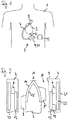
- FIG 1 shows schematically a body 1 of a patient in which a blood pump 2 for supporting a function of the heart 3 is implanted.
- the blood pump 2 has a motor, typically designed as an electric motor with a rotor, which is accommodated in a biocompatible pump housing 4 of the blood pump 2.
- Part of the pump housing 4 is widened and designed as a volute 25.
- the pump housing 4 is connected to a control device 5, which can also be implanted, as shown schematically.
- the control device 5 can also be completely or partially received in the implanted pump housing 4.
- the control device 5 is arranged extracorporeally.
- the pump housing 4 also comprises an inlet channel 6 connected to an inlet cannula of the pump housing 4, via which blood can be withdrawn from a chamber of the heart 3 and conveyed via a cannula 7 into a blood vessel 8.
- the control device 5 is set up to control the motor of the blood pump 2 to convey the blood.
- FIG. 2 shows a further schematic representation of the blood pump 2. Recurring features are provided with the same reference symbols in this figure and in the figures below.
- the electric motor of the blood pump comprises a stator accommodated in the pump housing 4 with windings 6.
- the rotor 7 of the electric motor is designed as a conveying element and has blades 8, 8 '.
- a flow channel 10 is delimited by an inner wall 9 of the pump housing 4, which is essentially cylindrical in the area shown, through which, when the blood pump 2 is operated, blood in the direction of the in Fig. 1 cannula 7 shown is promoted.
- a current flow electronically controlled by the control device 5 is generated in the windings 6 of the stator.
- the magnetic field generated by the current flow in the windings 6 can set a drive magnet within the rotor 7 and thus the entire rotor 7 in rotation for conveying the blood.
- the rotor 7 is through a in the Fig. 2 bearing part 11, shown only schematically, which can be configured, for example, as a sliding, spherical or active magnetic bearing, mounted axially and / or radially.
- an electronic control unit 12 for example for reading out sensors or for controlling the blood pump, is accommodated in the pump housing 4.
- the windings 6 of the stator, the bearing part 11 and the control unit 12 When the blood pump is in operation, the windings 6 of the stator, the bearing part 11 and the control unit 12 generate heat which is given off to a blood stream in the flow channel 10.
- a heat spreader 13 is received in the pump housing 4.
- a further heat spreader 13 ′ is received within the rotor 7.
- the heat generated by the windings 6 of the stator, the bearing part 11 and the control unit 12 is transferred to the blood in the flow channel 10 via the heat distributors 13, 13 ′.
- the heat distributors 13, 13 ' ensure a larger transition area.
- the heat spreader 13 transfers the heat via the inner wall 9 of the pump housing 4 to the blood.
- the further heat spreader 13 ′ transfers the heat to the blood via an outer wall 14 of the rotor 7.
- the outer wall 14 of the rotor 7 and the inner wall 9 of the pump housing 4, which each delimit the flow channel 10, are made of titanium or a titanium alloy.
- the heat distributors 13, 13 ' are made of copper and / or aluminum, for example, and therefore have a greater thermal conductivity than the outer wall 14 and the inner wall 9, so that the heat distributors 13, 13' efficiently distribute the heat over an enlarged area of the outer wall 14 or the inner wall 9 cause.
- a thermal conductivity of the heat distributors 13, 13 ' can be, for example, 200 or 400 W / (m K).
- a thermal insulator 22 is placed between the heat sources and the outside 21 of the pump housing 4 is provided.
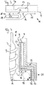
- the blood flow in the flow channel 10 forms a main blood flow 15 and critical points such as Fig. 3 illustrated.
- the largest volume flows are generally present in the area of the main blood flow 15.
- critical points in the flow channel 10 are formed by stagnation points, recirculation points, constriction points, or points of mechanical preload.
- a cross marked with reference numeral 16 represents, for example, a stagnation point.
- the recirculation flow 17 flows in a region of a constriction 18 between the inner wall 9 of the pump housing 4 and an obstacle 19 in a direction opposite to the main blood flow 15.
- the delimitation of the flow channel 10 represented by the inner wall 9 of the pump housing 4 can be formed by the outer wall 14 of the rotor 7.
- the obstacle 19 can be formed by a part of the pump housing 4, a part rigidly connected to the pump housing 4 or by the rotor 7, in particular by the blades 8, 8 ′ of the rotor 7.
- the recirculation flow 17 defines the recirculation point in the flow channel 10, which is identified by a cross with reference numeral 20. The same blood particles can flow past the recirculation point 20 several times during operation.
- the recirculation point 20 forms in the in Fig. 3
- the constriction point 20 can for example be defined by a gap width between the obstacle 19 and the inner wall 9 or outer wall 14 of less than 2 mm, in particular less than 1 mm.
- the point with reference numeral 20 also represents a Point of mechanical stress on the blood.
- the heat distributor 13 is set up to keep the heat to be transferred to the blood in the flow channel 10 away from the above-mentioned critical points 16, 20. It can be provided, for example, that the heat spreader 13 lies directly against a side of the wall 9 facing away from the flow channel 10 in areas of the main blood flow 15, but does not lie directly against the wall 9 in the areas of the critical points 16, 20. In the areas of the critical points 16, 20, a thermal insulator 23 is arranged between the heat spreader 13 and the wall 9, so that a heat transfer to the blood in the areas of the critical points 16, 20 is reduced.
- the various thermal insulators 22, 23 can be formed, for example, by polyimide films. It can be provided in further embodiments that the heat spreader 13 extends in such a way that it is not arranged in the areas of the critical points 16, 20, but only in areas of the main blood flow 15 behind the wall 9 and / or connected to it.
- the heat source 24 is shown only schematically. This can be any of the various heat sources mentioned above.
- the heat spreader 13 is connected to the heat source 24 in a thermally conductive manner and can, for example, lie directly against it or be at a distance of less than 1 mm from the heat source 24. It can also be provided that the heat spreader 13 is connected to the heat source 24 by means of a heat-conducting paste, a heat-conducting adhesive or a ceramic in order to produce good thermal contact.
- FIG 4 shows a further schematic view of the blood pump 2.
- the blood pump has the volute 25 formed by a widened area, which can be distinguished by a spiral or helical configuration or helical or helical flow properties.
- an outlet for the conveyed blood is arranged in the area of the volute 25, an outlet for the conveyed blood is arranged.
- a position of the outlet is indicated schematically by a dashed circle with reference number 29.
- the heat source is formed by the windings 6 of the stator accommodated in the pump housing 4.
- the windings 6 are between the thermal Isolators 22, 23 arranged.
- the windings 6 are connected to the heat spreader 13 via a thermally conductive and electrically insulating thermal bridge, for example via a ceramic, so that heat generated in the area of the windings 6 through ohmic or magnetic losses is conducted via the heat spreader 13 into the area of the volute 25.
- the thermal insulator 23 has a thin section 26 in the area of the volute 25, but a thick section 27 upstream in the area of the heat source and in the area of a stagnation point 16, so that the heat mainly in the area of the volute 25 reaches the blood in the flow channel 10 is transmitted.
- the thermal insulators 22, 23 are also electrically insulating in order to ensure adequate electrical insulation from the patient's blood or tissue.
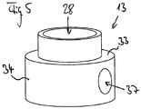
- FIG. 5 shows a perspective view of the heat spreader 13 already described above.
- the heat spreader 13 is flat, in one piece and ring-shaped, so that the heat spreader 13 has a through opening 28. In other embodiments, however, the heat spreader 13 is ring segment-shaped.
- the heat spreader 13 Inside the opening 28, the inner wall 9, not shown, of the pump housing 4, the flow channel 10 and the rotor 7 are received.
- the heat spreader 13 has a volute lining section 34 with a diameter which is larger than in an area which is arranged in the area of the heat source. A radially extending section 33 is arranged between these areas of different diameters.
- the heat is distributed through the heat spreader 13 to an enlarged release surface.
- the heat spreader 13 has an opening 37 extending in the radial direction in the area of the outlet 29.
- a thickness of the heat spreader 13 in the radial direction can be, for example, 0.5 mm in the volute lining section 34.
- the heat spreader 13 extends, for example, over at least one tenth, preferably over at least one sixth, of an axial extent of the pump housing 4.
- An inner area of the heat spreader 13 is, for example, 250 mm 2 .
- Fig. 6 the heat flow in the blood pump 2 is shown schematically.
- a heat output of 3 W is generated, for example.
- This heat output is transmitted, on the one hand, via a direct path 30, ie from the windings 6 radially inwards via the thermal insulator 23 and the inner wall 9 of the pump housing 4 to the blood in the flow channel 10.
- the vertical axis 31 indicates a temperature above a temperature of the blood.
- a greater thermal output can be dissipated than on the direct path 30.
- a thermal output released to the blood via the second path 32 can be 1.7 W.
- FIG Fig. 7 Another embodiment of a blood pump 2 is shown in FIG Fig. 7 shown.
- the rotor 7 of this blood pump 2 has an opening 38 which runs in the axial direction and through which a downwardly directed main blood flow is conveyed.
- a recirculation flow occurs, which flows in a direction which is opposite to the main blood flow.
- the rotor 7 has in its interior a rotor magnet 36, by means of which a rotation of the rotor 7 can be driven to convey blood through the stator.
- the stator is received in the pump housing 4 and comprises windings 6, 6 'and a magnetic core 35, for example iron.
- electronics 40 are accommodated in pump housing 4.
- heat can be generated both through ohmic losses in the electronics 40 and in the windings 6, 6 'and through magnetic reversal losses in the magnetic core 35, so that the electronics 40, the windings 6, 6' and the magnetic core 35 represent heat sources.
- the blood pump 2 has the heat spreader 13 for the efficient and safe transfer of heat from the heat sources to the blood.
- the heat spreader 13 distributes the heat from the heat sources to an enlarged area of the inner wall 9 of the pump housing 4 in the area of the volute 25.
- the heat spreader 13 is designed as explained in greater detail above and can reduce the thermal blood load in the gap and recirculation area 39.
Landscapes
- Health & Medical Sciences (AREA)
- Heart & Thoracic Surgery (AREA)
- Engineering & Computer Science (AREA)
- Cardiology (AREA)
- Biomedical Technology (AREA)
- Anesthesiology (AREA)
- Mechanical Engineering (AREA)
- Hematology (AREA)
- Life Sciences & Earth Sciences (AREA)
- Animal Behavior & Ethology (AREA)
- General Health & Medical Sciences (AREA)
- Public Health (AREA)
- Veterinary Medicine (AREA)
- External Artificial Organs (AREA)
Priority Applications (5)
| Application Number | Priority Date | Filing Date | Title |
|---|---|---|---|
| EP19159286.4A EP3701979A1 (fr) | 2019-02-26 | 2019-02-26 | Pompe à sang pouvant être implantée permettant de supporter une fonction cardiaque |
| DE112020000952.1T DE112020000952A5 (de) | 2019-02-26 | 2020-02-25 | Implantierbare Blutpumpe zum Unterstützen einer Herzfunktion |
| CN202080016385.4A CN113474037A (zh) | 2019-02-26 | 2020-02-25 | 用于辅助心脏功能的植入式血泵 |
| US17/434,281 US20220134084A1 (en) | 2019-02-26 | 2020-02-25 | Implantable blood pump for assisting a heart function |
| PCT/EP2020/054949 WO2020173966A1 (fr) | 2019-02-26 | 2020-02-25 | Pompe à sang implantable pour assistance de la fonction cardiaque |
Applications Claiming Priority (1)
| Application Number | Priority Date | Filing Date | Title |
|---|---|---|---|
| EP19159286.4A EP3701979A1 (fr) | 2019-02-26 | 2019-02-26 | Pompe à sang pouvant être implantée permettant de supporter une fonction cardiaque |
Publications (1)
| Publication Number | Publication Date |
|---|---|
| EP3701979A1 true EP3701979A1 (fr) | 2020-09-02 |
Family
ID=65598471
Family Applications (1)
| Application Number | Title | Priority Date | Filing Date |
|---|---|---|---|
| EP19159286.4A Withdrawn EP3701979A1 (fr) | 2019-02-26 | 2019-02-26 | Pompe à sang pouvant être implantée permettant de supporter une fonction cardiaque |
Country Status (5)
| Country | Link |
|---|---|
| US (1) | US20220134084A1 (fr) |
| EP (1) | EP3701979A1 (fr) |
| CN (1) | CN113474037A (fr) |
| DE (1) | DE112020000952A5 (fr) |
| WO (1) | WO2020173966A1 (fr) |
Cited By (1)
| Publication number | Priority date | Publication date | Assignee | Title |
|---|---|---|---|---|
| EP4443703A1 (fr) * | 2023-04-03 | 2024-10-09 | Levitronix GmbH | Entraînement rotatif électromagnétique et pompe centrifuge |
Citations (7)
| Publication number | Priority date | Publication date | Assignee | Title |
|---|---|---|---|---|
| WO1997049439A1 (fr) * | 1996-06-25 | 1997-12-31 | Rau Guenter | Pompe a sang |
| WO1998011347A1 (fr) * | 1996-09-13 | 1998-03-19 | Nimbus, Inc. | Pompe a sang electrique, implantable, a ecoulement axial, dotee d'un palier refroidi par le sang |
| WO1999049912A1 (fr) * | 1998-03-30 | 1999-10-07 | Nimbus, Inc. | Ensemble stator presentant un joint hermetique dans un moteur de pompe sanguine implantable |
| US20010053330A1 (en) * | 2000-06-20 | 2001-12-20 | Ntn Corporation | Magnetically levitated pump apparatus |
| US20050261543A1 (en) * | 2004-05-18 | 2005-11-24 | Yusuke Abe | Implantable artificial ventricular assist device |
| EP3181163A1 (fr) | 2015-12-14 | 2017-06-21 | Berlin Heart GmbH | Pompe à sang d'assistance cardiaque et son procédé de fonctionnement |
| WO2018209130A1 (fr) * | 2017-05-11 | 2018-11-15 | Tc1 Llc | Interconnexion thermique pour pompe à sang implantable |
Family Cites Families (10)
| Publication number | Priority date | Publication date | Assignee | Title |
|---|---|---|---|---|
| US4065264A (en) * | 1976-05-10 | 1977-12-27 | Shiley Laboratories, Inc. | Blood oxygenator with integral heat exchanger for regulating the temperature of blood in an extracorporeal circuit |
| US5853409A (en) * | 1994-06-27 | 1998-12-29 | E.P. Technologies, Inc. | Systems and apparatus for sensing temperature in body tissue |
| DE10245798B4 (de) * | 2002-10-01 | 2004-08-19 | Robert Bosch Gmbh | Elektrisch betriebener Ladeluftverdichter mit integrierter Luftkühlung |
| GB2417981A (en) * | 2004-09-14 | 2006-03-15 | Dana Automotive Ltd | Sealing arrangement for a canned motor pump |
| DE102013013700A1 (de) * | 2013-04-05 | 2014-10-09 | CircuLite GmbH | Implantierbare Blutpumpe, Blutpumpensystem und Verfahren zur Datenübertragung in einem Blutpumpensystem |
| US9408960B2 (en) * | 2013-12-19 | 2016-08-09 | Medtronic, Inc. | Partial radial heat exchanger and oxygenator |
| WO2016118781A2 (fr) * | 2015-01-22 | 2016-07-28 | Thoratec Corporation | Ensemble moteur avec échangeur de chaleur pour pompe de cathéter |
| US10926013B2 (en) * | 2017-04-07 | 2021-02-23 | Ecp Entwicklungsgesellschaft Mbh | Methods and systems for an external drive unit for an implantable heart assist pump |
| JP7168689B2 (ja) * | 2018-06-08 | 2022-11-09 | ピアーブルグ パンプ テクノロジー ゲゼルシャフト ミット ベシュレンクテル ハフツング | 電動冷却液ポンプ |
| PL3590559T3 (pl) * | 2018-07-02 | 2023-04-17 | Gambro Lundia Ab | Urządzenie medyczne do wprowadzania płynu do układu krążenia krwi pacjenta i sposób sterowania prądami upływu w urządzeniu medycznym wyposażonym w jednostkę grzewczą lub z nią połączonym |
-
2019
- 2019-02-26 EP EP19159286.4A patent/EP3701979A1/fr not_active Withdrawn
-
2020
- 2020-02-25 US US17/434,281 patent/US20220134084A1/en active Pending
- 2020-02-25 WO PCT/EP2020/054949 patent/WO2020173966A1/fr not_active Ceased
- 2020-02-25 DE DE112020000952.1T patent/DE112020000952A5/de active Pending
- 2020-02-25 CN CN202080016385.4A patent/CN113474037A/zh active Pending
Patent Citations (7)
| Publication number | Priority date | Publication date | Assignee | Title |
|---|---|---|---|---|
| WO1997049439A1 (fr) * | 1996-06-25 | 1997-12-31 | Rau Guenter | Pompe a sang |
| WO1998011347A1 (fr) * | 1996-09-13 | 1998-03-19 | Nimbus, Inc. | Pompe a sang electrique, implantable, a ecoulement axial, dotee d'un palier refroidi par le sang |
| WO1999049912A1 (fr) * | 1998-03-30 | 1999-10-07 | Nimbus, Inc. | Ensemble stator presentant un joint hermetique dans un moteur de pompe sanguine implantable |
| US20010053330A1 (en) * | 2000-06-20 | 2001-12-20 | Ntn Corporation | Magnetically levitated pump apparatus |
| US20050261543A1 (en) * | 2004-05-18 | 2005-11-24 | Yusuke Abe | Implantable artificial ventricular assist device |
| EP3181163A1 (fr) | 2015-12-14 | 2017-06-21 | Berlin Heart GmbH | Pompe à sang d'assistance cardiaque et son procédé de fonctionnement |
| WO2018209130A1 (fr) * | 2017-05-11 | 2018-11-15 | Tc1 Llc | Interconnexion thermique pour pompe à sang implantable |
Cited By (1)
| Publication number | Priority date | Publication date | Assignee | Title |
|---|---|---|---|---|
| EP4443703A1 (fr) * | 2023-04-03 | 2024-10-09 | Levitronix GmbH | Entraînement rotatif électromagnétique et pompe centrifuge |
Also Published As
| Publication number | Publication date |
|---|---|
| CN113474037A (zh) | 2021-10-01 |
| DE112020000952A5 (de) | 2021-12-02 |
| WO2020173966A1 (fr) | 2020-09-03 |
| US20220134084A1 (en) | 2022-05-05 |
Similar Documents
| Publication | Publication Date | Title |
|---|---|---|
| EP2807732B1 (fr) | Machine électrique et rotor pour refroidir la machine électrique | |
| EP0493704B1 (fr) | Moteur électrique | |
| EP1826888B1 (fr) | Moteur hors-bord électrique avec moteur à induit extérieur et convertisseur électronique intégré | |
| EP3628344A1 (fr) | Pompe a sang | |
| DE102019115835A1 (de) | Temperatursteuerungsanordnung für eine elektrische maschine | |
| DE10258778A1 (de) | Elektrische Maschine mit Heatpipes | |
| EP2905471B1 (fr) | Pompe de liquide de refroidissement électrique de véhicule automobile | |
| DE102014223909A1 (de) | Motorsystem | |
| WO2018193095A1 (fr) | Rotor pour moteur électrique avec revêtement de protection thermique et son procédé de fabrication | |
| EP2135567B1 (fr) | Moteur chirurgical, machine chirurgicale et procédé de fabrication d'un moteur chirurgical | |
| DE102006045178A1 (de) | Elektrische Maschine | |
| DE102016214405A1 (de) | Elektrische Maschine mit effizienterer Kühlung | |
| EP3701979A1 (fr) | Pompe à sang pouvant être implantée permettant de supporter une fonction cardiaque | |
| DE1628349A1 (de) | Luefterrad fuer Ventilatoren | |
| WO2016142190A1 (fr) | Machine électrique dotée d'un radiateur | |
| DE3545047A1 (de) | Manteleinheit mit zwangsumwaelzung fuer roentgenroehren mit drehanode | |
| EP2804291A1 (fr) | Carter pour un moteur électrique | |
| WO2017108893A1 (fr) | Pompe centrifuge, notamment pompe de circulation | |
| EP1869757B1 (fr) | Partie primaire d'un moteur lineaire et moteur lineaire la comprenant | |
| DE102013104117A1 (de) | Anordnung zur Kühlung einer elektrischen Maschine | |
| WO2009040212A1 (fr) | Machine dynamoélectrique sans boîtier | |
| DE102023109018A1 (de) | Statorsegment-wärmebrückensystem für einen axialflussmotor | |
| EP2321536A1 (fr) | Pompe | |
| DE102007036032A1 (de) | Unterwassermotor mit Wärmetauscher | |
| DE10245015B4 (de) | Elektromotor und Umwälzpumpe |
Legal Events
| Date | Code | Title | Description |
|---|---|---|---|
| PUAI | Public reference made under article 153(3) epc to a published international application that has entered the european phase |
Free format text: ORIGINAL CODE: 0009012 |
|
| STAA | Information on the status of an ep patent application or granted ep patent |
Free format text: STATUS: THE APPLICATION HAS BEEN PUBLISHED |
|
| AK | Designated contracting states |
Kind code of ref document: A1 Designated state(s): AL AT BE BG CH CY CZ DE DK EE ES FI FR GB GR HR HU IE IS IT LI LT LU LV MC MK MT NL NO PL PT RO RS SE SI SK SM TR |
|
| AX | Request for extension of the european patent |
Extension state: BA ME |
|
| STAA | Information on the status of an ep patent application or granted ep patent |
Free format text: STATUS: THE APPLICATION IS DEEMED TO BE WITHDRAWN |
|
| 18D | Application deemed to be withdrawn |
Effective date: 20210303 |