EP3701986B1 - Appareil de distribution de fluide et cartouche de distribution de fluide associée - Google Patents
Appareil de distribution de fluide et cartouche de distribution de fluide associée Download PDFInfo
- Publication number
- EP3701986B1 EP3701986B1 EP20158921.5A EP20158921A EP3701986B1 EP 3701986 B1 EP3701986 B1 EP 3701986B1 EP 20158921 A EP20158921 A EP 20158921A EP 3701986 B1 EP3701986 B1 EP 3701986B1
- Authority
- EP
- European Patent Office
- Prior art keywords
- end wall
- fluid
- cartridge
- proximal end
- electrical contacts
- Prior art date
- Legal status (The legal status is an assumption and is not a legal conclusion. Google has not performed a legal analysis and makes no representation as to the accuracy of the status listed.)
- Active
Links
Images


Classifications
-
- A—HUMAN NECESSITIES
- A61—MEDICAL OR VETERINARY SCIENCE; HYGIENE
- A61M—DEVICES FOR INTRODUCING MEDIA INTO, OR ONTO, THE BODY; DEVICES FOR TRANSDUCING BODY MEDIA OR FOR TAKING MEDIA FROM THE BODY; DEVICES FOR PRODUCING OR ENDING SLEEP OR STUPOR
- A61M31/00—Devices for introducing or retaining media, e.g. remedies, in cavities of the body
- A61M31/007—Injectors for solid bodies, e.g. suppositories
-
- A—HUMAN NECESSITIES
- A61—MEDICAL OR VETERINARY SCIENCE; HYGIENE
- A61M—DEVICES FOR INTRODUCING MEDIA INTO, OR ONTO, THE BODY; DEVICES FOR TRANSDUCING BODY MEDIA OR FOR TAKING MEDIA FROM THE BODY; DEVICES FOR PRODUCING OR ENDING SLEEP OR STUPOR
- A61M15/00—Inhalators
- A61M15/02—Inhalators with activated or ionised fluids, e.g. electrohydrodynamic [EHD] or electrostatic devices; Ozone-inhalators with radioactive tagged particles
- A61M15/025—Bubble jet droplet ejection devices
-
- B—PERFORMING OPERATIONS; TRANSPORTING
- B41—PRINTING; LINING MACHINES; TYPEWRITERS; STAMPS
- B41J—TYPEWRITERS; SELECTIVE PRINTING MECHANISMS, i.e. MECHANISMS PRINTING OTHERWISE THAN FROM A FORME; CORRECTION OF TYPOGRAPHICAL ERRORS
- B41J2/00—Typewriters or selective printing mechanisms characterised by the printing or marking process for which they are designed
- B41J2/005—Typewriters or selective printing mechanisms characterised by the printing or marking process for which they are designed characterised by bringing liquid or particles selectively into contact with a printing material
- B41J2/01—Ink jet
-
- A—HUMAN NECESSITIES
- A61—MEDICAL OR VETERINARY SCIENCE; HYGIENE
- A61K—PREPARATIONS FOR MEDICAL, DENTAL OR TOILETRY PURPOSES
- A61K9/00—Medicinal preparations characterised by special physical form
- A61K9/0012—Galenical forms characterised by the site of application
- A61K9/0043—Nose
-
- A—HUMAN NECESSITIES
- A61—MEDICAL OR VETERINARY SCIENCE; HYGIENE
- A61K—PREPARATIONS FOR MEDICAL, DENTAL OR TOILETRY PURPOSES
- A61K9/00—Medicinal preparations characterised by special physical form
- A61K9/0012—Galenical forms characterised by the site of application
- A61K9/0046—Ear
-
- A—HUMAN NECESSITIES
- A61—MEDICAL OR VETERINARY SCIENCE; HYGIENE
- A61M—DEVICES FOR INTRODUCING MEDIA INTO, OR ONTO, THE BODY; DEVICES FOR TRANSDUCING BODY MEDIA OR FOR TAKING MEDIA FROM THE BODY; DEVICES FOR PRODUCING OR ENDING SLEEP OR STUPOR
- A61M11/00—Sprayers or atomisers specially adapted for therapeutic purposes
-
- A—HUMAN NECESSITIES
- A61—MEDICAL OR VETERINARY SCIENCE; HYGIENE
- A61M—DEVICES FOR INTRODUCING MEDIA INTO, OR ONTO, THE BODY; DEVICES FOR TRANSDUCING BODY MEDIA OR FOR TAKING MEDIA FROM THE BODY; DEVICES FOR PRODUCING OR ENDING SLEEP OR STUPOR
- A61M31/00—Devices for introducing or retaining media, e.g. remedies, in cavities of the body
-
- B—PERFORMING OPERATIONS; TRANSPORTING
- B05—SPRAYING OR ATOMISING IN GENERAL; APPLYING FLUENT MATERIALS TO SURFACES, IN GENERAL
- B05B—SPRAYING APPARATUS; ATOMISING APPARATUS; NOZZLES
- B05B15/00—Details of spraying plant or spraying apparatus not otherwise provided for; Accessories
- B05B15/40—Filters located upstream of the spraying outlets
-
- B—PERFORMING OPERATIONS; TRANSPORTING
- B05—SPRAYING OR ATOMISING IN GENERAL; APPLYING FLUENT MATERIALS TO SURFACES, IN GENERAL
- B05B—SPRAYING APPARATUS; ATOMISING APPARATUS; NOZZLES
- B05B17/00—Apparatus for spraying or atomising liquids or other fluent materials, not covered by the preceding groups
- B05B17/04—Apparatus for spraying or atomising liquids or other fluent materials, not covered by the preceding groups operating with special methods
- B05B17/06—Apparatus for spraying or atomising liquids or other fluent materials, not covered by the preceding groups operating with special methods using ultrasonic or other kinds of vibrations
- B05B17/0607—Apparatus for spraying or atomising liquids or other fluent materials, not covered by the preceding groups operating with special methods using ultrasonic or other kinds of vibrations generated by electrical means, e.g. piezoelectric transducers
- B05B17/0638—Apparatus for spraying or atomising liquids or other fluent materials, not covered by the preceding groups operating with special methods using ultrasonic or other kinds of vibrations generated by electrical means, e.g. piezoelectric transducers spray being produced by discharging the liquid or other fluent material through a plate comprising a plurality of orifices
- B05B17/0646—Vibrating plates, i.e. plates being directly subjected to the vibrations, e.g. having a piezoelectric transducer attached thereto
-
- B—PERFORMING OPERATIONS; TRANSPORTING
- B05—SPRAYING OR ATOMISING IN GENERAL; APPLYING FLUENT MATERIALS TO SURFACES, IN GENERAL
- B05B—SPRAYING APPARATUS; ATOMISING APPARATUS; NOZZLES
- B05B17/00—Apparatus for spraying or atomising liquids or other fluent materials, not covered by the preceding groups
- B05B17/04—Apparatus for spraying or atomising liquids or other fluent materials, not covered by the preceding groups operating with special methods
- B05B17/06—Apparatus for spraying or atomising liquids or other fluent materials, not covered by the preceding groups operating with special methods using ultrasonic or other kinds of vibrations
- B05B17/0607—Apparatus for spraying or atomising liquids or other fluent materials, not covered by the preceding groups operating with special methods using ultrasonic or other kinds of vibrations generated by electrical means, e.g. piezoelectric transducers
- B05B17/0653—Details
- B05B17/0676—Feeding means
- B05B17/0684—Wicks or the like
-
- B—PERFORMING OPERATIONS; TRANSPORTING
- B41—PRINTING; LINING MACHINES; TYPEWRITERS; STAMPS
- B41J—TYPEWRITERS; SELECTIVE PRINTING MECHANISMS, i.e. MECHANISMS PRINTING OTHERWISE THAN FROM A FORME; CORRECTION OF TYPOGRAPHICAL ERRORS
- B41J2/00—Typewriters or selective printing mechanisms characterised by the printing or marking process for which they are designed
- B41J2/005—Typewriters or selective printing mechanisms characterised by the printing or marking process for which they are designed characterised by bringing liquid or particles selectively into contact with a printing material
- B41J2/01—Ink jet
- B41J2/17—Ink jet characterised by ink handling
- B41J2/175—Ink supply systems ; Circuit parts therefor
- B41J2/17503—Ink cartridges
- B41J2/17513—Inner structure
-
- B—PERFORMING OPERATIONS; TRANSPORTING
- B41—PRINTING; LINING MACHINES; TYPEWRITERS; STAMPS
- B41J—TYPEWRITERS; SELECTIVE PRINTING MECHANISMS, i.e. MECHANISMS PRINTING OTHERWISE THAN FROM A FORME; CORRECTION OF TYPOGRAPHICAL ERRORS
- B41J2/00—Typewriters or selective printing mechanisms characterised by the printing or marking process for which they are designed
- B41J2/005—Typewriters or selective printing mechanisms characterised by the printing or marking process for which they are designed characterised by bringing liquid or particles selectively into contact with a printing material
- B41J2/01—Ink jet
- B41J2/17—Ink jet characterised by ink handling
- B41J2/175—Ink supply systems ; Circuit parts therefor
- B41J2/17503—Ink cartridges
- B41J2/17553—Outer structure
-
- B—PERFORMING OPERATIONS; TRANSPORTING
- B41—PRINTING; LINING MACHINES; TYPEWRITERS; STAMPS
- B41J—TYPEWRITERS; SELECTIVE PRINTING MECHANISMS, i.e. MECHANISMS PRINTING OTHERWISE THAN FROM A FORME; CORRECTION OF TYPOGRAPHICAL ERRORS
- B41J2/00—Typewriters or selective printing mechanisms characterised by the printing or marking process for which they are designed
- B41J2/005—Typewriters or selective printing mechanisms characterised by the printing or marking process for which they are designed characterised by bringing liquid or particles selectively into contact with a printing material
- B41J2/01—Ink jet
- B41J2/17—Ink jet characterised by ink handling
- B41J2/175—Ink supply systems ; Circuit parts therefor
- B41J2/17563—Ink filters
-
- A—HUMAN NECESSITIES
- A61—MEDICAL OR VETERINARY SCIENCE; HYGIENE
- A61M—DEVICES FOR INTRODUCING MEDIA INTO, OR ONTO, THE BODY; DEVICES FOR TRANSDUCING BODY MEDIA OR FOR TAKING MEDIA FROM THE BODY; DEVICES FOR PRODUCING OR ENDING SLEEP OR STUPOR
- A61M11/00—Sprayers or atomisers specially adapted for therapeutic purposes
- A61M11/005—Sprayers or atomisers specially adapted for therapeutic purposes using ultrasonics
-
- A—HUMAN NECESSITIES
- A61—MEDICAL OR VETERINARY SCIENCE; HYGIENE
- A61M—DEVICES FOR INTRODUCING MEDIA INTO, OR ONTO, THE BODY; DEVICES FOR TRANSDUCING BODY MEDIA OR FOR TAKING MEDIA FROM THE BODY; DEVICES FOR PRODUCING OR ENDING SLEEP OR STUPOR
- A61M11/00—Sprayers or atomisers specially adapted for therapeutic purposes
- A61M11/04—Sprayers or atomisers specially adapted for therapeutic purposes operated by the vapour pressure of the liquid to be sprayed or atomised
- A61M11/041—Sprayers or atomisers specially adapted for therapeutic purposes operated by the vapour pressure of the liquid to be sprayed or atomised using heaters
- A61M11/042—Sprayers or atomisers specially adapted for therapeutic purposes operated by the vapour pressure of the liquid to be sprayed or atomised using heaters electrical
-
- A—HUMAN NECESSITIES
- A61—MEDICAL OR VETERINARY SCIENCE; HYGIENE
- A61M—DEVICES FOR INTRODUCING MEDIA INTO, OR ONTO, THE BODY; DEVICES FOR TRANSDUCING BODY MEDIA OR FOR TAKING MEDIA FROM THE BODY; DEVICES FOR PRODUCING OR ENDING SLEEP OR STUPOR
- A61M15/00—Inhalators
- A61M15/0001—Details of inhalators; Constructional features thereof
- A61M15/0021—Mouthpieces therefor
- A61M15/0025—Mouthpieces therefor with caps
-
- A—HUMAN NECESSITIES
- A61—MEDICAL OR VETERINARY SCIENCE; HYGIENE
- A61M—DEVICES FOR INTRODUCING MEDIA INTO, OR ONTO, THE BODY; DEVICES FOR TRANSDUCING BODY MEDIA OR FOR TAKING MEDIA FROM THE BODY; DEVICES FOR PRODUCING OR ENDING SLEEP OR STUPOR
- A61M15/00—Inhalators
- A61M15/06—Inhaling appliances shaped like cigars, cigarettes or pipes
-
- A—HUMAN NECESSITIES
- A61—MEDICAL OR VETERINARY SCIENCE; HYGIENE
- A61M—DEVICES FOR INTRODUCING MEDIA INTO, OR ONTO, THE BODY; DEVICES FOR TRANSDUCING BODY MEDIA OR FOR TAKING MEDIA FROM THE BODY; DEVICES FOR PRODUCING OR ENDING SLEEP OR STUPOR
- A61M15/00—Inhalators
- A61M15/08—Inhaling devices inserted into the nose
-
- A—HUMAN NECESSITIES
- A61—MEDICAL OR VETERINARY SCIENCE; HYGIENE
- A61M—DEVICES FOR INTRODUCING MEDIA INTO, OR ONTO, THE BODY; DEVICES FOR TRANSDUCING BODY MEDIA OR FOR TAKING MEDIA FROM THE BODY; DEVICES FOR PRODUCING OR ENDING SLEEP OR STUPOR
- A61M2210/00—Anatomical parts of the body
- A61M2210/06—Head
- A61M2210/0618—Nose
-
- A—HUMAN NECESSITIES
- A61—MEDICAL OR VETERINARY SCIENCE; HYGIENE
- A61M—DEVICES FOR INTRODUCING MEDIA INTO, OR ONTO, THE BODY; DEVICES FOR TRANSDUCING BODY MEDIA OR FOR TAKING MEDIA FROM THE BODY; DEVICES FOR PRODUCING OR ENDING SLEEP OR STUPOR
- A61M2210/00—Anatomical parts of the body
- A61M2210/06—Head
- A61M2210/0662—Ears
Definitions
- the present invention relates to fluidic dispensing devices, and, more particularly, to a fluidic dispensing apparatus and associated fluid dispensing cartridge.
- One type of fluid jetting cartridge is an inkjet cartridge for use with an inkjet printer, which includes a mechanism that scans the cartridge over a print medium, such as paper.
- a print medium such as paper.
- the size of the nozzle array is enlarged to cover a swath height on the print medium.
- a fluid such as in a medication dispenser (e.g., a nasal spray applicator) or a personal writing instrument (e.g., a handheld ink pen).
- a medication dispenser e.g., a nasal spray applicator
- a personal writing instrument e.g., a handheld ink pen
- an inkjet cartridge is not suitable in size or configuration to be inserted into a small orifice of a person, such as a nostril or ear canal.
- EP 1 768 858 A2 discloses a liquid feed unit intended to be mounted in a liquid spray instrument, the said unit comprising: a liquid cartridge, and a liquid spray head connected to the liquid cartridge.
- the liquid feed unit also comprises an energy supply source attached to the liquid cartridge so as to form a pre-assembled feed unit intended to be mounted directly in the liquid spray instrument.
- US 2006/077217 A1 discloses a medication delivery apparatus, comprising: a drop ejection device including at least 1000 drop generators; a fluid delivery system configured to deliver fluid to the drop generators; circuitry electrically coupled to the drop generators and configured to deliver drop ejection pulses to the drop generators; and a controller capable of delivering drop ejection pulses simultaneously to separate drop generators that are spaced apart on the drop ejection device.
- US 20170190174 A1 provides supports for microfluidic die that allow for nozzles of the microfluidic die to be on a different plane or face a different direction from electrical contacts on the same support.
- This includes a rigid support having electrical contacts on a different side of the rigid support with respect to a direction of ejection of the nozzles, and a semi-flexible support or semi-rigid support that allow the electrical contacts to be moved with respect to a direction of ejection of the nozzles.
- the semi-flexible and semi-rigid supports allow the die to be up to and beyond a 90 degree angle with respect to a plane of the electrical contacts.
- the different supports allow for a variety of positions of the microfluidic die with respect to a position of the electrical contacts.
- FR 2929861 A1 relates to a cartridge for a piezoelectric spraying device, comprising: - a reservoir containing a composition to be sprayed, - a membrane (130) intended to be vibrated for spraying the composition contained in the reservoir, - a feed system (140) dipping into the reservoir for supplying the spraying membrane, - a support (110), in one piece, for supporting the membrane (130) and the feed system (140) and maintaining them in a configuration predefined.
- US 9636430 B2 defines a cartridge for a microfluidic delivery system by a longitudinal axis.
- the cartridge includes a reservoir for containing a fluid composition.
- the cartridge also includes a nozzle operatively connected with the reservoir.
- the nozzle is in fluid communication with the reservoir for releasing the fluid composition.
- the cartridge includes an outer cover operatively connected with the reservoir.
- the outer cover comprises an orifice that is adjacent to the nozzle.
- An air flow path is formed by a gap between the reservoir and the outer cover.
- US 20160219938 A1 discloses a programmable smoking cessation system that includes an electronic vaporizing apparatus system, apparatus, nicotine management plan. Methods for the reduction of nicotine consumption based on the nicotine management plan to reduce or eliminate nicotine dependence.
- the systems, apparatuses and methods described herein utilize a digital processing device in combination with a vapor release mechanism to vaporize and blend nicotine and non-nicotine liquid substances from cartridge chambers to produce vapors configured to reduce nicotine consumption and dependence at a modulated rate over a specified period of time based on the nicotine management plan.
- the system and apparatus are configurable to track and report data acquired during use and provide feed back to a user and/or a clinical professional.
- WO 2018013120 A1 discloses an apparatus that includes a pipette dispenser to control dispensing of a volume to a dispensing location.
- a tip is operatively coupled to the pipette dispenser.
- the tip includes an electromechanical print head to dispense the volume from the pipette dispenser to the dispensing location based on a command from the pipette dispenser that indicates an amount of the volume to be dispensed from the print head.
- the present invention provides a fluidic dispensing apparatus and associated fluid dispensing cartridge, which is configured to be hand-manipulated and controlled, and is suitable in size and configuration for a particular application for personal use.
- the invention in one form is directed to a fluid dispensing cartridge that includes a housing body having a proximal end wall, a distal end wall, a fluid chamber, and a hollow throat portion.
- the fluid chamber is in fluid communication with the hollow throat portion.
- the proximal end wall provides a proximal termination of the fluid chamber and the distal end wall provides a distal termination of the hollow throat portion.
- the invention is characterized in that the housing body is an unitary structure further having an exterior surface and an intermediate wall.
- the exterior surface extends from the distal end wall to the proximal end wall, and the intermediate wall is located between, and is spaced from, the proximal end wall and the distal end wall along central longitudinal axis, and the fluid chamber is defined to be between the proximal end wall and the intermediate wall.
- a first plurality of electrical contacts face proximally from the proximal end wall.
- a fluid jetting chip has a plurality of fluid jetting nozzles.
- the exterior surface comprises the fluid chamber, the intermediate wall, and the hollow throat portion along a central longitudinal axis (52) as the unitary structure, wherein the housing body further comprises a circuit trace, the circuit trace being electrically connected to the first plurality of electrical contacts projecting proximally from the proximal end wall and the circuit trace being electrically connected to the fluid jetting chip, and wherein the circuit trace extends from the proximal end wall to the distal end wall along the exterior surface of the housing body and is attached to the exterior surface.
- the fluid jetting chip may be located on, and attached to, the distal end wall.
- the invention in another form is directed to a fluidic dispensing apparatus that includes a handle and the above mentioned fluid dispensing cartridge.
- the handle has a controller portion and a cartridge housing.
- the controller portion has a second plurality of electrical contacts.
- the cartridge housing is removably engaged with the controller portion.
- the cartridge housing has a distal opening.
- the fluid dispensing cartridge is positioned in the cartridge housing.
- the fluid dispensing cartridge has a housing body.
- the housing body has an exterior surface, a proximal end wall, a distal end wall, an intermediate wall, a fluid chamber, and a hollow throat portion.
- the fluid chamber is in fluid communication with the hollow throat portion.
- the distal end wall provides a distal termination of the hollow throat portion.
- the exterior surface extends from the distal end wall to the proximal end wall.
- the intermediate wall is located between, and is spaced from, the proximal end wall and the distal end wall along central longitudinal axis.
- the fluid chamber is defined to be between the proximal end wall and the intermediate wall.
- the hollow throat portion extends distally through the distal opening.
- the hollow throat portion has a distal end wall that mounts a fluid jetting chip on the distal end wall.
- the fluid jetting chip has a plurality of fluid jetting nozzles, and has a second plurality of electrical contacts that face proximally from the proximal end wall for engagement with the first plurality of electrical contacts of the controller portion.
- One advantage of the invention in general, is that the fluidic dispensing apparatus with the associated fluid dispensing cartridge may be hand-manipulated and controlled, with one hand, so as to position and operate the jetting chip for jetting a fluid toward a target area.
- Another advantage of the present invention in a medicinal application, for example, is that a portion of the apparatus is sized and shaped to fit through a small orifice and into a small passageway, such as a nostril or ear canal, so as to position the jetting chip as near the target area as possible.
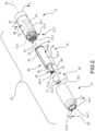
- a fluidic dispensing apparatus 10 which includes a controller portion 12, a cartridge housing 14, a fluid dispensing cartridge 16, and a cartridge throat cover 18 arranged along a longitudinal axis 20. Controller portion 12 and cartridge housing 14 in combination form a handle 10-1 of fluidic dispensing apparatus 10. As shown in Fig. 1 , cartridge housing 14 is removably engaged, i.e., connected, with controller portion 12. In the present invention, cartridge throat cover 18 is optional.
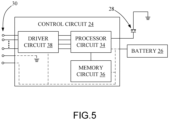
- controller portion 12 includes a controller housing 22, a control circuit 24, a battery 26, an actuator button 28, and a plurality of electrical contacts 30 (in the claims referred to as "a second plurality of electrical contacts (30)").
- Controller housing 22 includes a cavity 22-1 that contains control circuit 24 and battery 26.
- an exterior of controller housing 22 is generally cylindrical.
- battery 26 is connected to control circuit 24, and in turn supplies electrical power to all electrical components of control circuit 24, and to fluid dispensing cartridge 16 via control circuit 24.
- controller housing 22 has a coupling portion 22-2 and a distal end surface 22-3.
- Coupling portion 22-2 is configured for detachable attachment to a corresponding portion of cartridge housing 14.
- Coupling portion 22-2 may be, for example, radially opposed slots 32-1, 32-2 that rotationally receive a corresponding pair of radially opposed tabs 42-1, 42-2 of cartridge housing 14.
- coupling portion 22-2 of controller housing 22 is configured for quarter-turn detachable attachment to cartridge housing 14.
- the plurality of electrical contacts 30 of controller portion 12 is exposed at, and may alternatively project from, distal end surface 22-3 of controller housing 22.
- control circuit 24 includes a processor circuit 34, a memory circuit 36, and a driver circuit 38.
- Control circuit 24 may be formed as one or more Application Specific Integrated Circuits (ASIC).
- ASIC Application Specific Integrated Circuits
- Processor circuit 34 may have one or more programmable microprocessors and associated circuitry, such as an input/output interface, clock, buffers, memory, etc.
- Memory circuit 36 is communicatively coupled to processor circuit 34, e.g., via a bus circuit, and may include volatile memory circuits, such as random access memory (RAM), and non-volatile memory circuits, such as read only memory (ROM), electronically erasable programmable ROM (EEPROM), NOR flash memory, NAND flash memory, etc.
- volatile memory circuits such as random access memory (RAM)
- RAM random access memory
- non-volatile memory circuits such as read only memory (ROM), electronically erasable programmable ROM (EEPROM), NOR flash memory, NAND flash memory, etc.
- Processor circuit 34 of control circuit 24 is electrically connected to battery 26, and is electrically and communicatively connected to actuator button 28, memory circuit 36, and driver circuit 38.
- Driver circuit 38 is electrically connected to the plurality of electrical contacts 30 of controller portion 12.
- Processor circuit 34 of control circuit 24 is configured via software and/or firmware to operate fluid dispensing cartridge 16 (see also Figs. 1-4 ) for jetting a fluid contained in fluid dispensing cartridge 16.
- actuator button 28 supplies an input signal to processor circuit 34.
- processor circuit 34 executes control signals to generate cartridge control signals.
- the cartridge control signals are supplied by processor circuit 34 to driver circuit 38.
- Driver circuit 38 conditions the cartridge control signals (e.g., through impedance matching, voltage amplification, current amplification, etc.) as needed to be compatible with the electrical requirements of fluid dispensing cartridge 16, and supplies the conditioned cartridge control signals to respective electrical contacts of the plurality of electrical contacts 30.
- Control circuit 24 may also supply power and ground connections to fluid dispensing cartridge 16 via respective electrical contacts of the plurality of electrical contacts 30.
- the plurality of electrical contacts 30 supply the conditioned cartridge control signals, and power and ground, at a voltage level and/or current level suitable for the electrical jetting circuitry of fluid dispensing cartridge 16.
- cartridge housing 14 includes a proximal end 14-1, a coupling portion 14-2, a distal end 14-3, a chamber 14-4, a proximal opening 14-5, a distal opening 14-6, and an interior tapered annular surface 14-7.
- Chamber 14-4 extends between proximal end 14-1 and distal end 14-3 to define proximal opening 14-5 and distal opening 14-6.
- Each of chamber 14-4 and proximal opening 14-5 has a cross-sectional area, e.g., diameter, selected to axially receive fluid dispensing cartridge 16.
- Interior tapered annular surface 14-7 is located a distance 40 from proximal end 14-1. Interior tapered annular surface 14-7 generally transitions longitudinally from the larger cross-sectional area, e.g., diameter, of chamber 14-4 to the relatively smaller cross-sectional area, e.g., diameter, of distal opening 14-6. Interior tapered annular surface 14-7 defines a stop within chamber 14-4 to limit an extent of a lengthwise portion of fluid dispensing cartridge 16 that can be received in chamber 14-4. In operation, fluid dispensing cartridge 16 is axially received into chamber 14-4 of cartridge housing 14 to a depth defined by interior tapered annular surface 14-7. Also, in the present embodiment, interior tapered annular surface 14-7 will tend to radially center fluid dispensing cartridge 16 on longitudinal axis 20.
- Coupling portion 14-2 of cartridge housing 14 is configured for detachable attachment to coupling portion 22-2 of controller housing 22.
- Coupling portion 14-2 may include, for example, the pair of radially opposed tabs 42-1, 42-2 that are sized and shaped to axially and rotationally engage the radially opposed slots 32-1, 32-2 of controller housing 22.
- coupling portion 22-2 of controller housing 22 is configured for quarter-turn detachable attachment to coupling portion 14-2 of cartridge housing 14.
- Each of radially opposed tabs 42-1, 42-2 is inwardly-facing, i.e., extends toward longitudinal axis 20.
- fluid dispensing cartridge 16 when coupling portion 14-2 of cartridge housing 14 is attached to coupling portion 22-2 of controller housing 22, fluid dispensing cartridge 16 is in a state of compression between distal end surface 22-3 of controller housing 22 and interior tapered annular surface 14-7 of cartridge housing 14, such that fluid dispensing cartridge 16 is axially and radially restrained in chamber 14-4 of cartridge housing 14.
- fluid dispensing cartridge 16 is axially and radially restrained in fluidic dispensing apparatus 10 by the combined effect of interior tapered annular surface 14-7 of cartridge housing 14 and distal end surface 22-3 of controller housing 22.
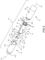
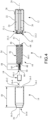
- fluid dispensing cartridge 16 includes a housing body 44 having a proximal end wall 46, an intermediate wall 48, a distal end wall 50, and a central longitudinal axis 52.
- Housing body 44 is a unitary structure, and has an exterior surface 44-1.
- central longitudinal axis 52 of fluid dispensing cartridge 16 lies on, and is coincident with, longitudinal axis 20 of fluidic dispensing apparatus 10.
- Proximal end wall 46 has a first surface area and distal end wall 50 has a second surface area, wherein the first surface area of proximal end wall 46 is greater than the second surface area of distal end wall 50.
- Intermediate wall 48 is located between, and is spaced from, proximal end wall 46 and distal end wall 50 along central longitudinal axis 52.
- a body region 54 between proximal end wall 46 and intermediate wall 48 defines a fluid chamber 56.
- a body region 58 between intermediate wall 48 and distal end wall 50 defines a hollow throat portion 60.
- Proximal end wall 46 provides a proximal termination of fluid chamber 56 and distal end wall 50 provides a distal termination of hollow throat portion 60.
- intermediate wall 48 has an opening 48-1 that facilitates fluid communication between fluid chamber 56 and hollow throat portion 60.
- fluid dispensing cartridge 16 is positioned in cartridge housing 14, prior to cartridge housing 14 being connected to controller portion 12.
- hollow throat portion 60 of fluid dispensing cartridge 16 extends distally through distal opening 14-6 of cartridge housing 14.
- Cartridge housing 14 is then connected to controller portion 12, which in turn establishes electrical connections between controller portion 12 and fluid dispensing cartridge 16.
- Fluid chamber 56 has a first cross-sectional area perpendicular to central longitudinal axis 52, and hollow throat portion 60 has a second cross-sectional area perpendicular to the central longitudinal axis 52, wherein the first cross-sectional area is greater than the second cross-sectional area throughout the longitudinal extent of each of fluid chamber 56 and hollow throat portion 60.
- fluid chamber 56 is cylindrical in shape.
- a longitudinal extent of each of fluid chamber 56 and hollow throat portion 60 is along the central longitudinal axis 52.
- a filter member 62 is located inside the housing body 44, and is positioned to cover opening 48-1 in intermediate wall 48 to separate fluid chamber 56 from hollow throat portion 60.
- Filter member 62 is porous, and in one embodiment is in the form of a mesh screen, e.g., a stainless steel mesh screen.
- Filter member 62 is connected to the intermediate wall 48, e.g., by heat staking, welding, adhesive, etc.
- An absorbent body 64 such as a foam or felt body, is located in and substantially fills fluid chamber 56.
- Absorbent body 64 contains a fluid that is to be ejected, i.e., jetted, from fluid dispensing cartridge 16.
- proximal end wall 46 also sometimes referred to as a lid
- body region 54 of housing body 44 e.g., ultrasonically welded
- fluid dispensing cartridge 16 includes a fluid jetting chip 66 that is located on, and is attached to, distal end wall 50 of housing body 44.
- a longitudinal extent of each of fluid chamber 56 and hollow throat portion 60 of housing body 44 is along the central longitudinal axis 52, and a center of each of fluid chamber 56, hollow throat portion 60, and fluid jetting chip 66 is located on central longitudinal axis 52.
- Fluid jetting chip 66 is configured as a plate-like structure having a planar extent formed generally as a nozzle plate layer and a silicon layer, as is well known in the art.
- the nozzle plate layer of fluid jetting chip 66 includes a plurality of fluid jetting nozzles 66-1, such as for example, two to twenty fluid jetting nozzles.
- an ejection mechanism such as a respective electrical heater (thermal) or piezoelectric (electromechanical) device that is individually associated with a respective fluid jetting nozzle of the plurality of fluid jetting nozzles 66-1.
- the general operation of such a fluid jetting chip is known in the micro-fluid ejection arts, such as in inkjet printing.
- fluid dispensing cartridge 16 includes a plurality of electrical contacts 68 (in the claims referred to as "a first plurality of electrical contacts (68)”) that is accessible at, and face proximally from, e.g., project proximally from, proximal end wall 46 of housing body 44.
- a center of proximal end wall 46 from which the plurality of electrical contacts 68 face proximally, and a center of fluid jetting chip 66 mounted to distal end wall 50 is located on central longitudinal axis 52.
- the plurality of electrical contacts 68 are distributed on proximal end wall 46, with the plurality of electrical contacts 68 being spaced from one another and electrically insulated from one another. In the present embodiment, at least a portion of the plurality of electrical contacts 68 is arranged in a circular pattern 68-1 at proximal end wall 46. It is contemplated that a different circular distribution pattern of the plurality of electrical contacts 68 may be made in the form of a concentric circular pattern. Also, it is contemplated that other distribution patterns, such as polygonal, may be used as an alternative to the circular distribution pattern.
- a circuit trace 70 such as a flexible tab circuit having a plurality of insulated conductors, is electrically connected to the plurality of electrical contacts 68 that face proximally from proximal end wall 46 of housing body 44, and is electrically connected to the fluid jetting chip 66 at distal end wall 50 of housing body 44, so as to establish electrical communication between the plurality of electrical contacts 68 and the plurality of jetting nozzles 66-1 of fluid jetting chip 66.
- circuit trace 70 extends from proximal end wall 46 to distal end wall 50 along exterior surface 44-1 of housing body 44.
- Circuit trace 70 lies on and follows the contour of the longitudinal extent of exterior surface 44-1 of housing body 44, including body region 54 having fluid chamber 56 and body region 58 having hollow throat portion 60. Circuit trace 70 is attached to exterior surface 44-1 of housing body 44, such as by adhesive or heat staking.
- hollow throat portion 60 includes a fluid channel 60-1 having a length that defines a separation distance between the fluid jetting chip 66 and the filter member 62. Stated differently, hollow throat portion 60 defines fluid channel 60-1 as having a length that, in part, defines a separation distance between fluid jetting chip 66 and the plurality of electrical contacts 68.
- the amount of fluid to be jetted dictates a larger container size for fluid chamber 56 of body region 54, but requires that distal end wall 50 and fluid jetting chip 66 have a relatively small area, and requires that hollow throat portion 60 have a length sufficient, so as to position fluid jetting chip 66 within an orifice (e.g., ear canal or nostril) at the desired application site.
- hollow throat portion 60 of fluid dispensing cartridge 16 is extended in length and with distal end wall 50 being made only large enough to house and mount fluid jetting chip 66. This, however, increases the volume of fluid that is accumulated distal to filter member 62, which is considered to be non-deliverable, and thus wasted, fluid.
- the volume of non-deliverable fluid is reduced.
- fluid channel 60-1 has an interior wall 60-2 that has a plurality of elongate protrusions 60-3 that project toward an interior of the fluid channel 60-1, e.g., generally toward central longitudinal axis 52.
- the plurality of elongate protrusions 60-3 is in the form of a plurality of elongate ribs that extend longitudinally in fluid channel 60-1.
- the plurality of elongate protrusions 60-3 may extend proximally into opening 48-1 of intermediate wall 48.
- a cross-section of fluid channel 60-1 tapers in a direction 71 from filter member 62 toward fluid jetting chip 66.
- interior wall 60-2 of hollow throat portion 60 has a frustoconical shape with the plurality of elongate protrusions 60-3 projecting toward an interior of fluid channel 60-1.
- fluid dispensing cartridge 16 is positioned in cartridge housing 14, prior to cartridge housing 14 being connected to controller portion 12.
- hollow throat portion 60 of fluid dispensing cartridge 16 extends distally through distal opening 14-6 of cartridge housing 14.
- Cartridge housing 14 is then connected to controller portion 12 to form handle 10-1, which in turn establishes electrical connections between the plurality of electrical contacts 30 of controller portion 12 and the plurality of electrical contacts 68 of fluid dispensing cartridge 16.
- fluid dispensing cartridge 16 may include cartridge throat cover 18.
- cartridge throat cover 18 may be installed on fluid dispensing cartridge 16 to cover hollow throat portion 60, either before or after fluid dispensing cartridge 16 is installed in handle 10-1, since the largest diameter of cartridge throat cover 18 is smaller than the diameter of distal opening 14-6 of cartridge housing 14.
- cartridge throat cover 18 may be either of a single use component, or a multiple use component.
- cartridge throat cover 18 may be disposed of and replaced, such as for sanitary reasons.
- cartridge throat cover 18 may be removed and cleaned, such as by immersing cartridge throat cover 18 in a sanitizing solution, and then reinstalled.
- cartridge throat cover 18 has a cover body 72 having a first end 72-1, a second end 72-2, and an internal cavity 72-3 that extends between first end 72-1 and second end 72-2.
- First end 72-1 has a cover opening 72-4.
- Each of cover opening 72-4 of first end 72-1 and internal cavity 72-3 has a size and shape that accommodates hollow throat portion 60 of housing body 44.
- each of cover opening 72-4 and internal cavity 72-3 is sized and shaped to be removably received over hollow throat portion 60 of housing body 44.
- Second end 72-2 of cover body 72 has a nozzle opening 72-5.
- Cover body 72 includes mounting features 72-6, e.g., a recess for clearance to circuit trace 70, to establish a detachable connection with fluid dispensing cartridge 16 when cartridge throat cover 18 is installed over hollow throat portion 60 of housing body 44 of fluid dispensing cartridge 16.
- cartridge throat cover 18 may be formed integral with cartridge housing 14 as a single-piece component.
- cartridge housing 14 having cartridge throat cover 18 may be either of a single use component, or a multiple use component.
- cartridge housing 14 having cartridge throat cover 18 may be disposed of and replaced, such as for sanitary reasons.
- cartridge housing 14 having cartridge throat cover 18 may be removed and cleaned, such as by immersing cartridge housing 14 having cartridge throat cover 18 in a sanitizing solution, and then reinstalled.
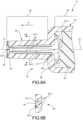
- FIGs. 8A and 8B depict another embodiment of a cartridge throat cover 118 suitable for use with fluid dispensing cartridge 16, and is a substitute for cartridge throat cover 18 depicted in Figs. 1-4 .
- Cartridge throat cover 118 has a cover body 172 having a first end 172-1, a second end 172-2, and an internal cavity 172-3 that extends between first end 172-1 and second end 172-2.
- first end 172-1 includes an annular lip 172-4 that projects radially in a direction away from central longitudinal axis 52.
- first end 172-1 of cartridge throat cover 118 has a cover opening 172-5.
- cover opening 172-5 of first end 172-1 and internal cavity 172-3 has a size and shape that accommodates hollow throat portion 60 of housing body 44 of fluid dispensing cartridge 16.
- annular lip 172-4 serves as a mounting feature.
- annular lip 172-4 is sized and shaped so as to annularly engage interior tapered annular surface 14-7 when cartridge throat cover 118 is inserted into proximal opening 14-5 of cartridge housing 14.
- cartridge throat cover 118 is positioned over hollow throat portion 60 of fluid dispensing cartridge 16 prior to cartridge housing 14 being connected to controller portion 12.
- annular lip 172-4 is wedged between interior tapered annular surface 14-7 of cartridge housing 14 and intermediate wall 48 of housing body 44 of fluid dispensing cartridge 16 when cartridge housing 14 is connected to controller portion 12.
- cover body 172 has a nozzle portion 172-6 that is proximal to second end 172-2.
- Nozzle portion 172-6 has a nozzle opening 172-7 located at second end 172-2.
- nozzle portion 172-6 is an angled nozzle portion that positions nozzle opening 172-7 to direct the jetted fluid from fluid jetting chip 66 of fluid dispensing cartridge 16 (see Figs. 2 and 4 ) in a direction away from central longitudinal axis 52, and likewise, away from longitudinal axis 20 of fluidic dispensing apparatus 10.
- cartridge throat cover may be realized, so that customization of fluidic dispensing apparatus 10 is very easy and inexpensive, and accommodates various use applications.
- Figs. 9 and 10 depict an alternative electrical connection of controller portion 12 and fluid dispensing cartridge 16.
- the plurality of electrical contacts 30 of controller portion 12 and the plurality of electrical contacts 68 of fluid dispensing cartridge 16 may be arranged to facilitate an edge connection, rather than an end connection.
- cartridge housing 14 and/or cartridge throat covers 18, 118 may be optional.
- a distal end portion 112 of controller portion 12 includes a socket portion 114 that includes a parallel arrangement of the plurality of electrical contacts 30.
- fluid dispensing cartridge 16 is fitted with a proximal end wall 146 connected to body region 54, as a substitute for proximal end wall 46 of the previous embodiments.
- Proximal end wall 146 has a mounting projection 148 that extends proximally from the proximal end wall 146.
- Mounting projection 148 is sized and shaped to be slidably received in socket portion 114 of controller portion 12 in a snug fit.
- each of the mounting projection 148 and fluid jetting chip 66 is located on central longitudinal axis 52.
- mounting projection 148 defines a first projection surface 148-1 and a second projection surface 148-2.
- the plurality of electrical contacts 68 may extend longitudinally, e.g., in parallel, along at least one of the first projection surface 148-1 and second projection surface 148-2 for engagement with the plurality of electrical contacts 30 of controller portion 12 when mounting projection 148 of this alternative embodiment of fluid dispensing cartridge 16 is slidably received in the socket portion 114 of controller portion 12.
Landscapes
- Health & Medical Sciences (AREA)
- General Health & Medical Sciences (AREA)
- Veterinary Medicine (AREA)
- Public Health (AREA)
- Life Sciences & Earth Sciences (AREA)
- Animal Behavior & Ethology (AREA)
- Engineering & Computer Science (AREA)
- Heart & Thoracic Surgery (AREA)
- Biomedical Technology (AREA)
- Anesthesiology (AREA)
- Hematology (AREA)
- Medicinal Chemistry (AREA)
- Chemical & Material Sciences (AREA)
- Pharmacology & Pharmacy (AREA)
- Epidemiology (AREA)
- Otolaryngology (AREA)
- Bioinformatics & Cheminformatics (AREA)
- Pulmonology (AREA)
- Infusion, Injection, And Reservoir Apparatuses (AREA)
- Ink Jet (AREA)
- Particle Formation And Scattering Control In Inkjet Printers (AREA)
- Media Introduction/Drainage Providing Device (AREA)
- Coating Apparatus (AREA)
- Disinfection, Sterilisation Or Deodorisation Of Air (AREA)
- Vascular Medicine (AREA)
- Cardiology (AREA)
- Nuclear Medicine, Radiotherapy & Molecular Imaging (AREA)
- Radiology & Medical Imaging (AREA)
Claims (16)
- Cartouche de distribution de liquide (16), comprenantun corps de boîtier (44) ayant une paroi d'extrémité proximale (46), une paroi d'extrémité distale (50), une chambre de fluide (56) et une partie de col creuse (60), la chambre de fluide (56) étant en communication de fluide avec la partie de col creuse (60), la paroi d'extrémité proximale (46) formant une fermeture proximale de la chambre de fluide (56) et la paroi d'extrémité distale (50) formant une fermeture distale de la partie de col creuse (60);dans lequel le corps de boîtier (44) est une structure unitaire comprenant en outreune surface extérieure (44-1) s'étendant de la paroi d'extrémité distale (50) à la paroi d'extrémité proximale (46), etune paroi intermédiaire (48) située entre la paroi d'extrémité proximale (46) et la paroi d'extrémité distale (50) et espacée de celles-ci le long d'un axe longitudinal central (52), la chambre de fluide (56) étant définie de manière à se trouver entre la paroi d'extrémité proximale (46) et la paroi intermédiaire (48);une première pluralité de contacts électriques (68) faisant face de manière proximale à la paroi d'extrémité proximale (46); etune puce à jet de fluide (66) comprenant une pluralité de buses à jet de fluide (66-1),dans lequel la surface extérieure (44-1) comprend la chambre de fluide (56), la paroi intermédiaire (48) et la partie de col creuse (60) le long de l'axe longitudinal central (52) en tant que structure unitaire,dans lequel le corps de boîtier (44) comprend en outre une piste conductrice (70), dans lequel la piste conductrice (70) est connectée électriquement à la première pluralité de contacts électriques (68) faisant saillie de manière proximale depuis la paroi d'extrémité proximale (46), et dans lequel la piste conductrice (70) est connectée électriquement à la puce à jet de fluide (66 ),caractérisé en ce quela piste conductrice (70) s'étend de la paroi d'extrémité proximale (46) à la paroi d'extrémité distale (50) le long de la surface extérieure (44-1) du corps de boîtier (44) et est fixée à la surface extérieure (44-1 ).
- Cartouche de distribution de liquide (16) selon la revendication 1, caractérisée en ce que la première pluralité de contacts électriques (68) est répartie sur la paroi d'extrémité proximale (46).
- Cartouche de distribution de liquide (16) selon la revendication 1 ou 2, caractérisée en ce qu'au moins une partie de la première pluralité de contacts électriques (68) est disposée selon un motif circulaire faisant saillie de la paroi d'extrémité proximale (46).
- Cartouche de distribution de liquide (16) selon l'une quelconque des revendications 1 à 3, caractérisée en ce qu'elle comprend une saillie de montage (148) s'étendant de manière proximale à partir de la paroi d'extrémité proximale, la saillie de montage (148) définissant une première surface en saillie (148-1) et une deuxième surface en saillie (148-2), et dans laquelle la première pluralité de contacts électriques (68) s'étend longitudinalement le long d'au moins l'une de la première surface en saillie (148-1) et de la deuxième surface en saillie (148-2).
- Cartouche de distribution de liquide (16) selon la revendication 4, caractérisée en ce que la saillie de fixation (148) et le jet de fluide chip (66) sont respectivement disposés sur l'axe longitudinal central (52).
- Cartouche de distribution de liquide (16) selon l'une quelconque des revendications 1 à 5, caractérisée en ce que la paroi d'extrémité proximale (46) présente une première région de surface et la paroi d'extrémité distale (50) présente une deuxième région de surface, la première région de surface étant plus grande que la deuxième région de surface.
- Cartouche de distribution de fluide (16) selon l'une quelconque des revendications 1 à 6, caractérisée en ce que la partie de col creuse (60) définit un canal de fluide (60-1) ayant une longueur qui définit partiellement une distance de séparation entre la puce de jet de fluide (66) et la première pluralité de contacts électriques (68).
- Cartouche de distribution de liquide (16) selon l'une quelconque des revendications 1 à 7, caractérisée en ce qu'un centre de chacune de la paroi d'extrémité proximale à partir de laquelle la première pluralité de contacts électriques (68) fait saillie et le jet de fluide chip (66) sont disposés sur l'axe longitudinal central (52).
- Dispositif de distribution de liquide (10), comprenantune poignée (10-1) comprenant une partie de commande (12) et un boîtier de cartouche (14), la partie de commande (12) comprenant une deuxième pluralité de contacts électriques (30), le boîtier de cartouche (14) étant engagé de manière amovible avec la partie de commande (12), le boîtier de cartouche (14) comprenant une ouverture distale (14-6); etla cartouche de distribution de liquide (16) selon la revendication 1, qui est disposée dans le boîtier de cartouche (14),dans lequel la partie de col creuse (60) s'étend distalement à travers l'ouverture distale (14-6), dans lequel la partie de col creuse (60) fixe la puce à jet de fluide (66) à la paroi d'extrémité distale (50), et dans lequel la cartouche de distribution de liquide (16) comprend la première pluralité de contacts électriques (68) faisant face proximalement à la paroi d'extrémité proximale (46) pour venir en prise avec la seconde pluralité de contacts électriques (30) de l'élément de commande (12).
- Dispositif de distribution de liquide (10) selon la revendication 9, caractérisé en ce que la première pluralité de contacts électriques (68) est répartie sur la paroi d'extrémité proximale (46).
- Dispositif de distribution de liquide (10) selon la revendication 9 ou 10, caractérisé en ce qu'au moins une partie de la première pluralité de contacts électriques (68) est disposée selon un motif circulaire faisant saillie de la paroi d'extrémité proximale (46).
- Dispositif de distribution de fluide (10) selon l'une quelconque des revendications 9 à 11, caractérisé en ce qu'il comprend une saillie de montage (148) s'étendant de manière proximale à partir de la paroi d'extrémité proximale (46), la saillie de montage (148) définissant une première surface en saillie (148-1) et une seconde surface en saillie (148-2), et dans lequel la première pluralité de contacts électriques (68) s'étend longitudinalement le long d'au moins l'une de la première surface en saillie (148-1) et de la seconde surface en saillie (148-2).
- Dispositif de distribution de liquide (10) selon la revendication 12, caractérisé en ce que la saillie de fixation (148) et la puce à jet de fluide (66) sont respectivement disposées sur l'axe longitudinal central (52).
- Dispositif de distribution de liquide (10) selon l'une quelconque des revendications 9 à 13, caractérisé en ce que la paroi d'extrémité proximale (46) présente une première région de surface et la paroi d'extrémité distale (50) présente une deuxième région de surface, la première région de surface étant plus grande que la deuxième région de surface.
- Dispositif de distribution de liquide (10) selon l'une quelconque des revendications 9 à 14, caractérisé en ce que la partie de col creuse (60) définit un canal de fluide (60-1) ayant une longueur définissant en partie une distance de séparation entre la puce à jet de fluide (66) et la première pluralité de contacts électriques (68).
- Dispositif de distribution de liquide (10) selon l'une quelconque des revendications 9 à 15, caractérisé en ce qu'il comprend un axe longitudinal central (52), et dans lequel un centre de chacune des parois d'extrémité proximale (46), à partir duquel la première pluralité de contacts électriques (68) fait face de manière proximale, et la puce à jet de fluide (66) sont disposés sur l'axe longitudinal central (52).
Applications Claiming Priority (1)
| Application Number | Priority Date | Filing Date | Title |
|---|---|---|---|
| US16/286,060 US11369781B2 (en) | 2019-02-26 | 2019-02-26 | Fluidic dispensing apparatus and associated fluid dispensing cartridge |
Publications (2)
| Publication Number | Publication Date |
|---|---|
| EP3701986A1 EP3701986A1 (fr) | 2020-09-02 |
| EP3701986B1 true EP3701986B1 (fr) | 2023-11-29 |
Family
ID=69902964
Family Applications (1)
| Application Number | Title | Priority Date | Filing Date |
|---|---|---|---|
| EP20158921.5A Active EP3701986B1 (fr) | 2019-02-26 | 2020-02-24 | Appareil de distribution de fluide et cartouche de distribution de fluide associée |
Country Status (4)
| Country | Link |
|---|---|
| US (1) | US11369781B2 (fr) |
| EP (1) | EP3701986B1 (fr) |
| JP (1) | JP7500985B2 (fr) |
| CN (1) | CN111605310B (fr) |
Families Citing this family (2)
| Publication number | Priority date | Publication date | Assignee | Title |
|---|---|---|---|---|
| JP7077461B1 (ja) | 2021-06-03 | 2022-05-30 | キヤノン株式会社 | 記録素子基板および温度検知装置 |
| JP7213593B1 (ja) | 2021-12-10 | 2023-01-27 | チャン ソン、ス | 美容および医療機器用ハンドピース |
Citations (2)
| Publication number | Priority date | Publication date | Assignee | Title |
|---|---|---|---|---|
| US20060077217A1 (en) * | 2004-10-13 | 2006-04-13 | Xiaofeng Yang | Thermal drop generator |
| EP1768858A2 (fr) * | 2004-07-22 | 2007-04-04 | Société BIC | Unite d'alimentation de liquide pour instrument de pulverisation de liquide et instrument comprenant ladite unite d'alimentation en liquide |
Family Cites Families (18)
| Publication number | Priority date | Publication date | Assignee | Title |
|---|---|---|---|---|
| JP2839997B2 (ja) * | 1992-12-09 | 1998-12-24 | 株式会社リコー | 記録ヘッドユニット |
| MXPA02010884A (es) | 2000-05-05 | 2003-03-27 | Aerogen Ireland Ltd | Aparato y metodo para el suministro de medicamentos al sistema respiratorio. |
| US6814265B2 (en) * | 2003-03-06 | 2004-11-09 | Alcon, Inc. | Device for dispensing fluid medicine |
| JP4035462B2 (ja) * | 2003-03-19 | 2008-01-23 | キヤノン株式会社 | 薬剤吐出装置 |
| FR2929861B1 (fr) | 2008-04-11 | 2011-11-11 | Oreal | Cartouche pour dispositif de pulverisation piezoelectrique et appareil de pulverisation associe. |
| EP2113178A1 (fr) | 2008-04-30 | 2009-11-04 | Philip Morris Products S.A. | Système de fumée chauffé électriquement avec une portion de stockage liquide |
| WO2010126586A1 (fr) | 2009-04-27 | 2010-11-04 | Aardvark Medical, Llc | Dispositifs et procédés d'irrigation et d'aspiration |
| UA112883C2 (uk) | 2011-12-08 | 2016-11-10 | Філіп Морріс Продактс С.А. | Пристрій для утворення аерозолю з капілярним примежовим шаром |
| US9220302B2 (en) | 2013-03-15 | 2015-12-29 | R.J. Reynolds Tobacco Company | Cartridge for an aerosol delivery device and method for assembling a cartridge for a smoking article |
| EP3043663A4 (fr) | 2013-09-13 | 2017-05-10 | Nicodart Inc. | Appareil électronique programmable de vaporisation et système d'arrêt du tabac |
| JP6660370B2 (ja) | 2014-07-11 | 2020-03-11 | フィリップ・モーリス・プロダクツ・ソシエテ・アノニム | 液体ニコチン供与源を備えるエアロゾル形成カートリッジ |
| GB201511358D0 (en) | 2015-06-29 | 2015-08-12 | Nicoventures Holdings Ltd | Electronic aerosol provision systems |
| WO2017011419A1 (fr) | 2015-07-10 | 2017-01-19 | Pax Labs, Inc. | Dispositifs de vaporisation sans mèche et procédés |
| US9636430B2 (en) * | 2015-09-16 | 2017-05-02 | The Procter & Gamble Company | Microfluidic delivery system and cartridge having an outer cover |
| US10118391B2 (en) | 2015-12-30 | 2018-11-06 | Stmicroelectronics, Inc. | Microfluidic die on a support with at least one other die |
| US11253850B2 (en) * | 2016-07-14 | 2022-02-22 | Hewlett-Packard Development Company, L.P. | Pipette dispenser tip utilizing print head |
| PL3487325T3 (pl) | 2016-07-25 | 2020-12-14 | Philip Morris Products S.A. | Wkład do układu wytwarzania aerozolu z zabezpieczeniem ogrzewacza |
| US10130122B2 (en) | 2016-10-28 | 2018-11-20 | Funai Electric Co., Ltd. | Supply item for vapor generating device |
-
2019
- 2019-02-26 US US16/286,060 patent/US11369781B2/en active Active
-
2020
- 2020-02-14 JP JP2020023382A patent/JP7500985B2/ja active Active
- 2020-02-20 CN CN202010105104.4A patent/CN111605310B/zh not_active Expired - Fee Related
- 2020-02-24 EP EP20158921.5A patent/EP3701986B1/fr active Active
Patent Citations (2)
| Publication number | Priority date | Publication date | Assignee | Title |
|---|---|---|---|---|
| EP1768858A2 (fr) * | 2004-07-22 | 2007-04-04 | Société BIC | Unite d'alimentation de liquide pour instrument de pulverisation de liquide et instrument comprenant ladite unite d'alimentation en liquide |
| US20060077217A1 (en) * | 2004-10-13 | 2006-04-13 | Xiaofeng Yang | Thermal drop generator |
Also Published As
| Publication number | Publication date |
|---|---|
| JP7500985B2 (ja) | 2024-06-18 |
| JP2020138013A (ja) | 2020-09-03 |
| US11369781B2 (en) | 2022-06-28 |
| EP3701986A1 (fr) | 2020-09-02 |
| CN111605310B (zh) | 2022-04-15 |
| US20200269027A1 (en) | 2020-08-27 |
| CN111605310A (zh) | 2020-09-01 |
Similar Documents
| Publication | Publication Date | Title |
|---|---|---|
| US20250098772A1 (en) | Method of making e-vaping device with ejectors to eject droplets | |
| US7131599B2 (en) | Atomizing device | |
| US6085740A (en) | Liquid dispensing apparatus and methods | |
| EP3701986B1 (fr) | Appareil de distribution de fluide et cartouche de distribution de fluide associée | |
| US5758637A (en) | Liquid dispensing apparatus and methods | |
| EP2189175B1 (fr) | Nébuliseur | |
| EP3941225B1 (fr) | Dispositif de distribution d'aérosol | |
| EP3702046A1 (fr) | Appareil de distribution de fluide et cartouche de distribution de fluide associée | |
| WO2003043826A1 (fr) | Tete de jet de liquide | |
| CA2585329A1 (fr) | Nebulisateur comprenant des moyens pour mettre en surpression un liquide a nebuliser | |
| WO2006070884A1 (fr) | Pulverisateur electrostatique | |
| JP2003038646A (ja) | 医用噴霧装置 | |
| JP2003154655A (ja) | 液体吐出ヘッド | |
| US7364267B2 (en) | Liquid ejection head | |
| CN220027399U (zh) | 喷头组件、雾化器及雾化装置 | |
| CN218898344U (zh) | 一种雾化组件、雾化器及雾化装置 | |
| CN109832666B (zh) | 喷液装置及电子烟 | |
| JP2003010738A (ja) | 噴霧ノズル装置及び噴霧ノズル | |
| HK1135060A (en) | Mist spray apparatus |
Legal Events
| Date | Code | Title | Description |
|---|---|---|---|
| PUAI | Public reference made under article 153(3) epc to a published international application that has entered the european phase |
Free format text: ORIGINAL CODE: 0009012 |
|
| STAA | Information on the status of an ep patent application or granted ep patent |
Free format text: STATUS: THE APPLICATION HAS BEEN PUBLISHED |
|
| AK | Designated contracting states |
Kind code of ref document: A1 Designated state(s): AL AT BE BG CH CY CZ DE DK EE ES FI FR GB GR HR HU IE IS IT LI LT LU LV MC MK MT NL NO PL PT RO RS SE SI SK SM TR |
|
| AX | Request for extension of the european patent |
Extension state: BA ME |
|
| STAA | Information on the status of an ep patent application or granted ep patent |
Free format text: STATUS: REQUEST FOR EXAMINATION WAS MADE |
|
| 17P | Request for examination filed |
Effective date: 20201103 |
|
| RBV | Designated contracting states (corrected) |
Designated state(s): AL AT BE BG CH CY CZ DE DK EE ES FI FR GB GR HR HU IE IS IT LI LT LU LV MC MK MT NL NO PL PT RO RS SE SI SK SM TR |
|
| STAA | Information on the status of an ep patent application or granted ep patent |
Free format text: STATUS: EXAMINATION IS IN PROGRESS |
|
| 17Q | First examination report despatched |
Effective date: 20220311 |
|
| REG | Reference to a national code |
Ref country code: DE Ref country code: DE Ref legal event code: R079 Ref document number: 602020021705 Country of ref document: DE Free format text: PREVIOUS MAIN CLASS: A61M0011000000 Ipc: A61M0015020000 |
|
| GRAP | Despatch of communication of intention to grant a patent |
Free format text: ORIGINAL CODE: EPIDOSNIGR1 |
|
| STAA | Information on the status of an ep patent application or granted ep patent |
Free format text: STATUS: GRANT OF PATENT IS INTENDED |
|
| RIC1 | Information provided on ipc code assigned before grant |
Ipc: A61M 15/08 20060101ALN20230623BHEP Ipc: A61M 15/06 20060101ALN20230623BHEP Ipc: A61M 11/00 20060101ALN20230623BHEP Ipc: A61M 11/04 20060101ALN20230623BHEP Ipc: A61M 15/00 20060101ALN20230623BHEP Ipc: B05B 17/06 20060101ALI20230623BHEP Ipc: B05B 15/40 20180101ALI20230623BHEP Ipc: A61M 15/02 20060101AFI20230623BHEP |
|
| INTG | Intention to grant announced |
Effective date: 20230727 |
|
| GRAS | Grant fee paid |
Free format text: ORIGINAL CODE: EPIDOSNIGR3 |
|
| GRAA | (expected) grant |
Free format text: ORIGINAL CODE: 0009210 |
|
| STAA | Information on the status of an ep patent application or granted ep patent |
Free format text: STATUS: THE PATENT HAS BEEN GRANTED |
|
| RAP3 | Party data changed (applicant data changed or rights of an application transferred) |
Owner name: FUNAI ELECTRIC CO., LTD. |
|
| RIN1 | Information on inventor provided before grant (corrected) |
Inventor name: MARRA III, MICHAEL A. Inventor name: ANDERSON JR., JAMES D. |
|
| AK | Designated contracting states |
Kind code of ref document: B1 Designated state(s): AL AT BE BG CH CY CZ DE DK EE ES FI FR GB GR HR HU IE IS IT LI LT LU LV MC MK MT NL NO PL PT RO RS SE SI SK SM TR |
|
| REG | Reference to a national code |
Ref country code: GB Ref legal event code: FG4D |
|
| REG | Reference to a national code |
Ref country code: CH Ref legal event code: EP |
|
| REG | Reference to a national code |
Ref country code: DE Ref legal event code: R096 Ref document number: 602020021705 Country of ref document: DE |
|
| REG | Reference to a national code |
Ref country code: IE Ref legal event code: FG4D |
|
| REG | Reference to a national code |
Ref country code: LT Ref legal event code: MG9D |
|
| REG | Reference to a national code |
Ref country code: NL Ref legal event code: MP Effective date: 20231129 |
|
| PG25 | Lapsed in a contracting state [announced via postgrant information from national office to epo] |
Ref country code: GR Free format text: LAPSE BECAUSE OF FAILURE TO SUBMIT A TRANSLATION OF THE DESCRIPTION OR TO PAY THE FEE WITHIN THE PRESCRIBED TIME-LIMIT Effective date: 20240301 |
|
| PG25 | Lapsed in a contracting state [announced via postgrant information from national office to epo] |
Ref country code: IS Free format text: LAPSE BECAUSE OF FAILURE TO SUBMIT A TRANSLATION OF THE DESCRIPTION OR TO PAY THE FEE WITHIN THE PRESCRIBED TIME-LIMIT Effective date: 20240329 |
|
| PG25 | Lapsed in a contracting state [announced via postgrant information from national office to epo] |
Ref country code: LT Free format text: LAPSE BECAUSE OF FAILURE TO SUBMIT A TRANSLATION OF THE DESCRIPTION OR TO PAY THE FEE WITHIN THE PRESCRIBED TIME-LIMIT Effective date: 20231129 |
|
| PG25 | Lapsed in a contracting state [announced via postgrant information from national office to epo] |
Ref country code: ES Free format text: LAPSE BECAUSE OF FAILURE TO SUBMIT A TRANSLATION OF THE DESCRIPTION OR TO PAY THE FEE WITHIN THE PRESCRIBED TIME-LIMIT Effective date: 20231129 |
|
| PG25 | Lapsed in a contracting state [announced via postgrant information from national office to epo] |
Ref country code: LT Free format text: LAPSE BECAUSE OF FAILURE TO SUBMIT A TRANSLATION OF THE DESCRIPTION OR TO PAY THE FEE WITHIN THE PRESCRIBED TIME-LIMIT Effective date: 20231129 Ref country code: IS Free format text: LAPSE BECAUSE OF FAILURE TO SUBMIT A TRANSLATION OF THE DESCRIPTION OR TO PAY THE FEE WITHIN THE PRESCRIBED TIME-LIMIT Effective date: 20240329 Ref country code: GR Free format text: LAPSE BECAUSE OF FAILURE TO SUBMIT A TRANSLATION OF THE DESCRIPTION OR TO PAY THE FEE WITHIN THE PRESCRIBED TIME-LIMIT Effective date: 20240301 Ref country code: ES Free format text: LAPSE BECAUSE OF FAILURE TO SUBMIT A TRANSLATION OF THE DESCRIPTION OR TO PAY THE FEE WITHIN THE PRESCRIBED TIME-LIMIT Effective date: 20231129 Ref country code: BG Free format text: LAPSE BECAUSE OF FAILURE TO SUBMIT A TRANSLATION OF THE DESCRIPTION OR TO PAY THE FEE WITHIN THE PRESCRIBED TIME-LIMIT Effective date: 20240229 |
|
| PGFP | Annual fee paid to national office [announced via postgrant information from national office to epo] |
Ref country code: DE Payment date: 20240206 Year of fee payment: 5 |
|
| REG | Reference to a national code |
Ref country code: AT Ref legal event code: MK05 Ref document number: 1635482 Country of ref document: AT Kind code of ref document: T Effective date: 20231129 |
|
| PG25 | Lapsed in a contracting state [announced via postgrant information from national office to epo] |
Ref country code: NL Free format text: LAPSE BECAUSE OF FAILURE TO SUBMIT A TRANSLATION OF THE DESCRIPTION OR TO PAY THE FEE WITHIN THE PRESCRIBED TIME-LIMIT Effective date: 20231129 |
|
| PG25 | Lapsed in a contracting state [announced via postgrant information from national office to epo] |
Ref country code: SE Free format text: LAPSE BECAUSE OF FAILURE TO SUBMIT A TRANSLATION OF THE DESCRIPTION OR TO PAY THE FEE WITHIN THE PRESCRIBED TIME-LIMIT Effective date: 20231129 Ref country code: RS Free format text: LAPSE BECAUSE OF FAILURE TO SUBMIT A TRANSLATION OF THE DESCRIPTION OR TO PAY THE FEE WITHIN THE PRESCRIBED TIME-LIMIT Effective date: 20231129 Ref country code: PL Free format text: LAPSE BECAUSE OF FAILURE TO SUBMIT A TRANSLATION OF THE DESCRIPTION OR TO PAY THE FEE WITHIN THE PRESCRIBED TIME-LIMIT Effective date: 20231129 Ref country code: NO Free format text: LAPSE BECAUSE OF FAILURE TO SUBMIT A TRANSLATION OF THE DESCRIPTION OR TO PAY THE FEE WITHIN THE PRESCRIBED TIME-LIMIT Effective date: 20240229 Ref country code: NL Free format text: LAPSE BECAUSE OF FAILURE TO SUBMIT A TRANSLATION OF THE DESCRIPTION OR TO PAY THE FEE WITHIN THE PRESCRIBED TIME-LIMIT Effective date: 20231129 Ref country code: LV Free format text: LAPSE BECAUSE OF FAILURE TO SUBMIT A TRANSLATION OF THE DESCRIPTION OR TO PAY THE FEE WITHIN THE PRESCRIBED TIME-LIMIT Effective date: 20231129 Ref country code: HR Free format text: LAPSE BECAUSE OF FAILURE TO SUBMIT A TRANSLATION OF THE DESCRIPTION OR TO PAY THE FEE WITHIN THE PRESCRIBED TIME-LIMIT Effective date: 20231129 |
|
| PG25 | Lapsed in a contracting state [announced via postgrant information from national office to epo] |
Ref country code: DK Free format text: LAPSE BECAUSE OF FAILURE TO SUBMIT A TRANSLATION OF THE DESCRIPTION OR TO PAY THE FEE WITHIN THE PRESCRIBED TIME-LIMIT Effective date: 20231129 |
|
| PG25 | Lapsed in a contracting state [announced via postgrant information from national office to epo] |
Ref country code: CZ Free format text: LAPSE BECAUSE OF FAILURE TO SUBMIT A TRANSLATION OF THE DESCRIPTION OR TO PAY THE FEE WITHIN THE PRESCRIBED TIME-LIMIT Effective date: 20231129 Ref country code: AT Free format text: LAPSE BECAUSE OF FAILURE TO SUBMIT A TRANSLATION OF THE DESCRIPTION OR TO PAY THE FEE WITHIN THE PRESCRIBED TIME-LIMIT Effective date: 20231129 |
|
| PG25 | Lapsed in a contracting state [announced via postgrant information from national office to epo] |
Ref country code: SK Free format text: LAPSE BECAUSE OF FAILURE TO SUBMIT A TRANSLATION OF THE DESCRIPTION OR TO PAY THE FEE WITHIN THE PRESCRIBED TIME-LIMIT Effective date: 20231129 |
|
| PG25 | Lapsed in a contracting state [announced via postgrant information from national office to epo] |
Ref country code: SM Free format text: LAPSE BECAUSE OF FAILURE TO SUBMIT A TRANSLATION OF THE DESCRIPTION OR TO PAY THE FEE WITHIN THE PRESCRIBED TIME-LIMIT Effective date: 20231129 Ref country code: SK Free format text: LAPSE BECAUSE OF FAILURE TO SUBMIT A TRANSLATION OF THE DESCRIPTION OR TO PAY THE FEE WITHIN THE PRESCRIBED TIME-LIMIT Effective date: 20231129 Ref country code: RO Free format text: LAPSE BECAUSE OF FAILURE TO SUBMIT A TRANSLATION OF THE DESCRIPTION OR TO PAY THE FEE WITHIN THE PRESCRIBED TIME-LIMIT Effective date: 20231129 Ref country code: IT Free format text: LAPSE BECAUSE OF FAILURE TO SUBMIT A TRANSLATION OF THE DESCRIPTION OR TO PAY THE FEE WITHIN THE PRESCRIBED TIME-LIMIT Effective date: 20231129 Ref country code: EE Free format text: LAPSE BECAUSE OF FAILURE TO SUBMIT A TRANSLATION OF THE DESCRIPTION OR TO PAY THE FEE WITHIN THE PRESCRIBED TIME-LIMIT Effective date: 20231129 Ref country code: DK Free format text: LAPSE BECAUSE OF FAILURE TO SUBMIT A TRANSLATION OF THE DESCRIPTION OR TO PAY THE FEE WITHIN THE PRESCRIBED TIME-LIMIT Effective date: 20231129 Ref country code: CZ Free format text: LAPSE BECAUSE OF FAILURE TO SUBMIT A TRANSLATION OF THE DESCRIPTION OR TO PAY THE FEE WITHIN THE PRESCRIBED TIME-LIMIT Effective date: 20231129 Ref country code: AT Free format text: LAPSE BECAUSE OF FAILURE TO SUBMIT A TRANSLATION OF THE DESCRIPTION OR TO PAY THE FEE WITHIN THE PRESCRIBED TIME-LIMIT Effective date: 20231129 |
|
| PG25 | Lapsed in a contracting state [announced via postgrant information from national office to epo] |
Ref country code: PT Free format text: LAPSE BECAUSE OF FAILURE TO SUBMIT A TRANSLATION OF THE DESCRIPTION OR TO PAY THE FEE WITHIN THE PRESCRIBED TIME-LIMIT Effective date: 20240401 |
|
| PG25 | Lapsed in a contracting state [announced via postgrant information from national office to epo] |
Ref country code: PT Free format text: LAPSE BECAUSE OF FAILURE TO SUBMIT A TRANSLATION OF THE DESCRIPTION OR TO PAY THE FEE WITHIN THE PRESCRIBED TIME-LIMIT Effective date: 20240401 |
|
| REG | Reference to a national code |
Ref country code: DE Ref legal event code: R097 Ref document number: 602020021705 Country of ref document: DE |
|
| PG25 | Lapsed in a contracting state [announced via postgrant information from national office to epo] |
Ref country code: MC Free format text: LAPSE BECAUSE OF FAILURE TO SUBMIT A TRANSLATION OF THE DESCRIPTION OR TO PAY THE FEE WITHIN THE PRESCRIBED TIME-LIMIT Effective date: 20231129 |
|
| REG | Reference to a national code |
Ref country code: CH Ref legal event code: PL |
|
| PLBE | No opposition filed within time limit |
Free format text: ORIGINAL CODE: 0009261 |
|
| STAA | Information on the status of an ep patent application or granted ep patent |
Free format text: STATUS: NO OPPOSITION FILED WITHIN TIME LIMIT |
|
| PG25 | Lapsed in a contracting state [announced via postgrant information from national office to epo] |
Ref country code: LU Free format text: LAPSE BECAUSE OF NON-PAYMENT OF DUE FEES Effective date: 20240224 |
|
| PG25 | Lapsed in a contracting state [announced via postgrant information from national office to epo] |
Ref country code: CH Free format text: LAPSE BECAUSE OF NON-PAYMENT OF DUE FEES Effective date: 20240229 |
|
| GBPC | Gb: european patent ceased through non-payment of renewal fee |
Effective date: 20240229 |
|
| PG25 | Lapsed in a contracting state [announced via postgrant information from national office to epo] |
Ref country code: SI Free format text: LAPSE BECAUSE OF FAILURE TO SUBMIT A TRANSLATION OF THE DESCRIPTION OR TO PAY THE FEE WITHIN THE PRESCRIBED TIME-LIMIT Effective date: 20231129 |
|
| PG25 | Lapsed in a contracting state [announced via postgrant information from national office to epo] |
Ref country code: SI Free format text: LAPSE BECAUSE OF FAILURE TO SUBMIT A TRANSLATION OF THE DESCRIPTION OR TO PAY THE FEE WITHIN THE PRESCRIBED TIME-LIMIT Effective date: 20231129 Ref country code: LU Free format text: LAPSE BECAUSE OF NON-PAYMENT OF DUE FEES Effective date: 20240224 Ref country code: CH Free format text: LAPSE BECAUSE OF NON-PAYMENT OF DUE FEES Effective date: 20240229 |
|
| 26N | No opposition filed |
Effective date: 20240830 |
|
| REG | Reference to a national code |
Ref country code: BE Ref legal event code: MM Effective date: 20240229 |
|
| PG25 | Lapsed in a contracting state [announced via postgrant information from national office to epo] |
Ref country code: BE Free format text: LAPSE BECAUSE OF NON-PAYMENT OF DUE FEES Effective date: 20240229 |
|
| PG25 | Lapsed in a contracting state [announced via postgrant information from national office to epo] |
Ref country code: GB Free format text: LAPSE BECAUSE OF NON-PAYMENT OF DUE FEES Effective date: 20240229 |
|
| PG25 | Lapsed in a contracting state [announced via postgrant information from national office to epo] |
Ref country code: FR Free format text: LAPSE BECAUSE OF NON-PAYMENT OF DUE FEES Effective date: 20240229 |
|
| PG25 | Lapsed in a contracting state [announced via postgrant information from national office to epo] |
Ref country code: IE Free format text: LAPSE BECAUSE OF NON-PAYMENT OF DUE FEES Effective date: 20240224 |
|
| PG25 | Lapsed in a contracting state [announced via postgrant information from national office to epo] |
Ref country code: IE Free format text: LAPSE BECAUSE OF NON-PAYMENT OF DUE FEES Effective date: 20240224 Ref country code: GB Free format text: LAPSE BECAUSE OF NON-PAYMENT OF DUE FEES Effective date: 20240229 Ref country code: FR Free format text: LAPSE BECAUSE OF NON-PAYMENT OF DUE FEES Effective date: 20240229 Ref country code: BE Free format text: LAPSE BECAUSE OF NON-PAYMENT OF DUE FEES Effective date: 20240229 |
|
| REG | Reference to a national code |
Ref country code: DE Ref legal event code: R081 Ref document number: 602020021705 Country of ref document: DE Owner name: BRADY WORLDWIDE, INC., MILWAUKEE, US Free format text: FORMER OWNER: FUNAI ELECTRIC CO., LTD., DAITO, OSAKA, JP Ref country code: DE Ref legal event code: R082 Ref document number: 602020021705 Country of ref document: DE Representative=s name: BOULT WADE TENNANT LLP, DE |
|
| PG25 | Lapsed in a contracting state [announced via postgrant information from national office to epo] |
Ref country code: CY Free format text: LAPSE BECAUSE OF FAILURE TO SUBMIT A TRANSLATION OF THE DESCRIPTION OR TO PAY THE FEE WITHIN THE PRESCRIBED TIME-LIMIT; INVALID AB INITIO Effective date: 20200224 |
|
| REG | Reference to a national code |
Ref country code: DE Ref legal event code: R119 Ref document number: 602020021705 Country of ref document: DE |
|
| PG25 | Lapsed in a contracting state [announced via postgrant information from national office to epo] |
Ref country code: HU Free format text: LAPSE BECAUSE OF FAILURE TO SUBMIT A TRANSLATION OF THE DESCRIPTION OR TO PAY THE FEE WITHIN THE PRESCRIBED TIME-LIMIT; INVALID AB INITIO Effective date: 20200224 |
|
| PG25 | Lapsed in a contracting state [announced via postgrant information from national office to epo] |
Ref country code: FI Free format text: LAPSE BECAUSE OF FAILURE TO SUBMIT A TRANSLATION OF THE DESCRIPTION OR TO PAY THE FEE WITHIN THE PRESCRIBED TIME-LIMIT Effective date: 20231129 |
|
| PG25 | Lapsed in a contracting state [announced via postgrant information from national office to epo] |
Ref country code: TR Free format text: LAPSE BECAUSE OF FAILURE TO SUBMIT A TRANSLATION OF THE DESCRIPTION OR TO PAY THE FEE WITHIN THE PRESCRIBED TIME-LIMIT Effective date: 20231129 |
|
| PG25 | Lapsed in a contracting state [announced via postgrant information from national office to epo] |
Ref country code: DE Free format text: LAPSE BECAUSE OF NON-PAYMENT OF DUE FEES Effective date: 20250902 |