EP3702005A1 - Talonnière - Google Patents
Talonnière Download PDFInfo
- Publication number
- EP3702005A1 EP3702005A1 EP20156651.0A EP20156651A EP3702005A1 EP 3702005 A1 EP3702005 A1 EP 3702005A1 EP 20156651 A EP20156651 A EP 20156651A EP 3702005 A1 EP3702005 A1 EP 3702005A1
- Authority
- EP
- European Patent Office
- Prior art keywords
- holding
- heel
- ski
- unit
- automatic
- Prior art date
- Legal status (The legal status is an assumption and is not a legal conclusion. Google has not performed a legal analysis and makes no representation as to the accuracy of the status listed.)
- Granted
Links
Images


Classifications
-
- A—HUMAN NECESSITIES
- A63—SPORTS; GAMES; AMUSEMENTS
- A63C—SKATES; SKIS; ROLLER SKATES; DESIGN OR LAYOUT OF COURTS, RINKS OR THE LIKE
- A63C9/00—Ski bindings
- A63C9/006—Ski bindings with a climbing wedge
-
- A—HUMAN NECESSITIES
- A63—SPORTS; GAMES; AMUSEMENTS
- A63C—SKATES; SKIS; ROLLER SKATES; DESIGN OR LAYOUT OF COURTS, RINKS OR THE LIKE
- A63C9/00—Ski bindings
- A63C9/08—Ski bindings yieldable or self-releasing in the event of an accident, i.e. safety bindings
- A63C9/0807—Ski bindings yieldable or self-releasing in the event of an accident, i.e. safety bindings for both towing and downhill skiing
-
- A—HUMAN NECESSITIES
- A63—SPORTS; GAMES; AMUSEMENTS
- A63C—SKATES; SKIS; ROLLER SKATES; DESIGN OR LAYOUT OF COURTS, RINKS OR THE LIKE
- A63C9/00—Ski bindings
- A63C9/08—Ski bindings yieldable or self-releasing in the event of an accident, i.e. safety bindings
- A63C9/084—Ski bindings yieldable or self-releasing in the event of an accident, i.e. safety bindings with heel hold-downs, e.g. swingable
- A63C9/0843—Ski bindings yieldable or self-releasing in the event of an accident, i.e. safety bindings with heel hold-downs, e.g. swingable with a plurality of mobile jaws
-
- A—HUMAN NECESSITIES
- A63—SPORTS; GAMES; AMUSEMENTS
- A63C—SKATES; SKIS; ROLLER SKATES; DESIGN OR LAYOUT OF COURTS, RINKS OR THE LIKE
- A63C9/00—Ski bindings
- A63C9/08—Ski bindings yieldable or self-releasing in the event of an accident, i.e. safety bindings
- A63C9/084—Ski bindings yieldable or self-releasing in the event of an accident, i.e. safety bindings with heel hold-downs, e.g. swingable
- A63C9/0845—Ski bindings yieldable or self-releasing in the event of an accident, i.e. safety bindings with heel hold-downs, e.g. swingable the body or base or a jaw pivoting about a vertical axis, i.e. side release
-
- A—HUMAN NECESSITIES
- A63—SPORTS; GAMES; AMUSEMENTS
- A63C—SKATES; SKIS; ROLLER SKATES; DESIGN OR LAYOUT OF COURTS, RINKS OR THE LIKE
- A63C9/00—Ski bindings
- A63C9/08—Ski bindings yieldable or self-releasing in the event of an accident, i.e. safety bindings
- A63C9/084—Ski bindings yieldable or self-releasing in the event of an accident, i.e. safety bindings with heel hold-downs, e.g. swingable
- A63C9/0846—Details of the release or step-in mechanism
-
- A—HUMAN NECESSITIES
- A63—SPORTS; GAMES; AMUSEMENTS
- A63C—SKATES; SKIS; ROLLER SKATES; DESIGN OR LAYOUT OF COURTS, RINKS OR THE LIKE
- A63C9/00—Ski bindings
- A63C9/08—Ski bindings yieldable or self-releasing in the event of an accident, i.e. safety bindings
- A63C9/086—Ski bindings yieldable or self-releasing in the event of an accident, i.e. safety bindings using parts which are fixed on the shoe of the user and are releasable from the ski binding
-
- A—HUMAN NECESSITIES
- A63—SPORTS; GAMES; AMUSEMENTS
- A63C—SKATES; SKIS; ROLLER SKATES; DESIGN OR LAYOUT OF COURTS, RINKS OR THE LIKE
- A63C9/00—Ski bindings
- A63C2009/008—Ski bindings with a binding element sliding along a rail during use or setting
Definitions
- the invention relates to an automatic heel unit for a ski binding, in particular a touring ski binding.
- This automatic heel unit comprises a base unit for fastening on the surface of a ski and a heel holder with at least one holding means for holding a ski boot in a heel area of the ski boot, the automatic heel unit having a descent configuration in which the heel holder is in a holding position and the at least one holding means can interact with the heel area of the ski boot held in the ski binding in such a way that the heel area of the ski boot is held down in a lowered position.
- the automatic heel unit comprises a radial bearing, by means of which the heel holder is mounted on the base unit so as to be pivotable about a substantially vertically aligned, geometric pivot axis relative to the base unit and can thus be pivoted away from its holding position starting from its holding position along an adjustment path around the pivot axis
- Radial bearing has a pin which is formed on a first of the two units of base unit and heel holder, and the radial bearing has a receptacle which is formed on a second of the two units of base unit and heel holder, wherein the pin is rotatably inserted into the receptacle, whereby the heel holder is pivotably mounted on the base unit about the pivot axis relative to the base unit.
- the automatic heel unit comprises a pretensioning device, by means of which the heel holder can be pretensioned towards its holding position in a first area of the adjustment path, the pretensioning device comprising a first pushing element with a first positioning structure and an elastic element, the first pushing element being generated by the elastic element and along an alignment axis of the elastic element in a first direction aligned first force with the first positioning structure can be pressed against a first counter structure when the heel holder is located in the first region of the adjustment path to preload the heel holder in the first region of the adjustment path towards its holding position.
- the pretensioning device comprising a first pushing element with a first positioning structure and an elastic element, the first pushing element being generated by the elastic element and along an alignment axis of the elastic element in a first direction aligned first force with the first positioning structure can be pressed against a first counter structure when the heel holder is located in the first region of the adjustment path to preload the heel holder in the first region of the adjustment path towards its holding position.
- Automatic heel units in the technical field mentioned above are known. Their task is to ensure that the heel area of the ski boot is reliably fixed on the ski in a downhill configuration.
- some such automatic heel machines also enable a safety release based on the descent configuration, in which the heel area of the ski boot is released. This can be, for example, a safety release in the forward direction or a lateral safety release.
- the term “safety release” means that the automatic heel unit releases the heel area of the ski boot if the energy of an impact on the ski boot, ski binding or ski exceeds a predetermined value. It is irrelevant whether the automatic heel is in the downhill configuration or in another configuration after the ski boot has been released. In the event of impacts whose energy does not exceed this value, the automatic heel unit remains in the downhill configuration and keeps the heel area of the ski boot locked in a position lowered towards the ski.
- an automatic heel device generally depends on which function the ski binding to which the automatic heel device belongs is to fulfill.
- Downhill ski bindings for example, are only used for downhill skiing and skiing on ski lifts.
- touring ski bindings are also used for walking on skis, in particular for climbing with the help of climbing skins attached to the skis.
- Cross-country bindings on the other hand, are used for cross-country skiing and telemark bindings for skiing with the telemark technique.
- downhill ski bindings only have to ensure a reliable fixation of the ski boot on the ski in a so-called holding position.
- Some automatic heel machines also have a so-called entry configuration or release configuration, in which they enable entry into the ski binding.
- touring ski bindings have a walking position in which the ski boot, like cross-country and telemark bindings, can be pivoted about an axis oriented horizontally in the transverse direction of the ski and can be lifted off the ski in the heel area, which enables a joint movement between the ski boot and the ski for walking.
- the automatic heel can be in the walking position of a touring ski binding in different configurations depending on the construction and type of touring ski binding. For example, he can be in his departure configuration, in an entry configuration, in a release configuration or in a walking configuration.
- a heel machine is also required for such a cross-country or telemark binding, by means of which the ski boot can be locked in its heel area towards the ski, and which the heel area of the ski boot can be used for walking in the walking position of the cross-country or telemark binding.
- Touring ski bindings can basically be divided into two types.
- One type comprises a ski boot carrier which can be pivoted relative to the ski and on which the ski boot is held by binding jaws.
- a representative member of this type of touring ski bindings is in the EP 0 754 079 B1 (Fritschi AG).
- the second type relies on ski boots with stiff soles.
- the ski boot is pivotably mounted in its toe area in a ski-mounted front machine.
- the automatic heel unit is also firmly attached to the ski at a distance from the automatic front unit adapted to the length of the ski boot sole and holds the ski boot down in the heel area in the downhill position of the binding.
- ski boots suitable for this type of binding typically have two lateral recesses in the toe area for the pivotable mounting in the front automat. Furthermore, in the heel area they have recesses which are open to the rear and into which the holding means of the automatic heel unit can engage.
- a (fictitious) ski is often used as a reference system to describe such binding systems, it being assumed that the binding is mounted on this ski. This habit is taken over in the present text.
- the term "longitudinal direction of the ski” means along the alignment of the longitudinal axis of the ski.
- "parallel to the ski” means oriented along the longitudinal axis of the ski for an elongate object. For a flat object, however, the term “parallel to the ski” means aligned parallel to the sliding surface of the ski.
- transverse direction of the ski means a direction transverse to the longitudinal direction of the ski, which, however, does not have to be oriented precisely at right angles to the longitudinal axis of the ski.
- ski center in turn means a center of the ski, seen in the transverse direction of the ski, while the term “ski fixed” means not movable with respect to the ski. It should also be noted that terms that do not contain the word “ski” also refer to the reference system of the (fictitious) ski.
- front”, “rear”, “top”, “bottom” and “side” refer to “front”, “back”, “top”, “bottom” and “side” of the ski.
- terms such as “horizontal” and “vertical” also relate to the ski, where “horizontal” means lying in a plane parallel to the ski and “vertical” means oriented perpendicular to this plane.
- a touring ski binding of the second type introduced above is in the EP 0 199 098 A2 (Barthel) and is sold under the name Dynafit.
- a front machine of this system has two clamping parts, each with a pin aligned in the transverse direction of the ski, which engage in recesses in the toe area of the ski boot from the sides when entering the touring ski binding.
- the pins form a pivot bearing of the ski boot, on which the ski boot can be pivoted relative to the ski about an axis oriented horizontally in the transverse direction of the ski.
- a heel machine of this system which is separate from the front machine, has a base element for attachment to a ski and a heel holder for holding the ski boot in the heel area of the ski boot.
- the heel holder is mounted on a vertically oriented pin arranged on the base element and is thereby mounted on the base element so as to be pivotable about a vertically oriented, geometric pivot axis relative to the base element.
- the heel holder In the downhill configuration of the automatic heel unit, the heel holder is in a holding position. In this holding position, two pins arranged on the heel holder are oriented towards the front automaton, whereby they can engage in recesses in the heel of the ski boot and thereby lock the ski boot in a position lowered towards the ski.
- the ski boot When getting into touring ski bindings, the ski boot is first stored in the front machine. Then the heel of the ski boot is lowered onto the pins of the heel holder from above. Since the recesses in the heel of the ski boot are largely open at the bottom, the recesses are thereby guided over the pins, whereupon the pins snap into locking recesses in the recesses.
- both pins can be pressed apart against a spring force, whereby they slide out of the locking depressions and the recesses and can release the heel of the ski boot upwards.
- both pins are each arranged on a lever, the levers each being mounted on the heel holder so that they can pivot in a horizontal plane. Both levers are preloaded with a spring force, so that the two pins are pressed towards each other. By adjusting the spring force, the force can be specified which is required to enable forward tripping. This enables a safety release in the forward direction.
- the automatic heel unit also enables a lateral safety release.
- the heel holder can be pivoted around a vertically aligned, geometric pivot axis against a spring force on both sides until the two pins are pivoted to the side and the heel area of the ski boot is released on the corresponding side.
- the pin of the base element has a flat surface on its rear side, which is aligned horizontally to the rear with its normal vector. A piston mounted in the heel holder and pretensioned forwards by a spring is pressed against this surface of the pin in the holding position.
- the piston When the heel holder is pivoted away from its holding position about the pivot axis on one of the two sides, the piston is pivoted with it and tilted relative to the surface of the pin. This moves the piston backwards against the spring force. The heel holder is thus biased towards its holding position due to the spring force.
- the preload of the spring By setting the preload of the spring, the value can be specified which must be exceeded by the energy of an impact on the ski, ski binding or ski so that a lateral safety release occurs.
- a heel machine according to EP 0 199 098 A2 can also be brought into an ascent position by turning the heel holder around the pivot axis by the skier, as with a lateral safety release, until the two pins have pivoted to the side out of the path of the heel of the ski boot.
- the heel holder has several rotational positions in which the pins are pivoted out of the movement path of the heel. These individual rotational positions are each predetermined by a spring catch for locking the heel holder. When the heel holder is in one of these rotational positions, the movement path of the heel of the ski boot is free and the ski boot can be lowered down to the ski.
- a support arranged on the heel holder is in each case pivoted a certain distance from the ski in the path of movement of the heel of the ski boot.
- Each such support prevents the ski boot from lowering towards the ski at a different distance from the ski.
- different climbing aids can be set by positioning the heel holder in the various rotational positions.
- the automatic heel unit according to EP 0 199 098 A2 (Barthel) is constructed very compactly. However, it has the disadvantage that the mounting of the heel holder on the base element is not particularly stable.
- the object of the invention is to create an automatic heel unit belonging to the technical field mentioned at the beginning, which is of compact construction and at the same time enables the heel holder to be stably supported on the base element.
- the elastic element is arranged in the pin, the orientation axis of the elastic element being oriented perpendicular to the pivot axis, and the first counter-structure being assigned to the second of the two units comprising the base unit and heel holder.
- the base unit can thus be designed in one piece or in several pieces.
- the base unit can EP 0 199 098 A2 (Barthel) be designed in one piece as a base element. If the base unit is constructed in several pieces, it can, for example, as in the case of WO 2012/024809 A1 (Fritschi AG - Swiss Bindings) described automatic heel a base plate for attachment to the surface of a ski and a slide which is mounted on the base plate in the longitudinal direction of the ski and on which the heel holder is mounted pivotably about the pivot axis.
- the position of the slide in the longitudinal direction of the ski relative to the base plate can be adjusted by means of a screw in order to be able to adjust the position of the heel holder in the longitudinal direction of the ski relative to the front automatic device of the ski binding, so that the ski binding is adapted to different sized ski boots can be.
- the slide can be pretensioned with a spring to a front position relative to the base plate, the heel holder together with the slide can be pushed backwards against the pretension of the spring in order to avoid changes in distance between the automatic front end and the heel holder, which occur when the ski is bent can compensate.
- the heel holder forms a unit and can be designed in one piece or in several pieces.
- the heel holder can also, for example, as in the EP 3 167 943 A1 (Fritschi AG) described by a heel hold-down device as well as a forwardly protruding heel support structure with two forwardly protruding, elongated projections seen in the vertical direction.
- the heel holder can also be used, for example, as in the EP 0 199 098 A2 (Barthel) described to be designed as a unit with two forward pointing pins.
- the heel holder can also be designed differently.
- the pin is formed on a first of the two units comprising the base unit and heel holder, while the receptacle is formed on a second of the two units comprising the base unit and heel holder.
- the pin can be formed on the base unit, while the receptacle is formed on the heel holder.
- the pin can also be formed on the heel holder, while the receptacle can be formed on the base unit.
- the radial bearing is designed, as long as the radial bearing has a pin and a receptacle, the pin being inserted rotatably into the receptacle, whereby the heel holder can pivot about a substantially vertically oriented, geometric pivot axis relative to the base unit the base unit is stored.
- the radial bearing preferably prevents a translational movement of the heel holder relative to the base unit in a direction perpendicular to the pivot axis.
- the base unit can also have two elements have which are movable relative to one another perpendicular to the pivot axis, wherein the radial bearing is arranged on one of these two elements.
- the other of the two elements of the base unit can perform a translational movement relative to the heel holder perpendicular to the pivot axis.
- a movement of the element of the base unit on which the radial bearing is arranged relative to the heel holder perpendicular to the pivot axis of the radial bearing is still prevented.
- the formulation continues to apply that the radial bearing prevents a translational movement of the heel holder relative to the base unit perpendicular to the pivot axis.
- the base unit has two elements which can be moved relative to one another perpendicular to the pivot axis, the radial bearing being arranged on one of these two elements, there is the possibility that the pivot axis is displaced relative to the base unit when the heel holder moves along the adjustment path or that the pivot axis remains in an unchanged position relative to the base unit or relative to the element of the base unit on which the radial bearing is arranged.
- the elastic element of the prestressing device can thus be designed in one piece or in several pieces.
- the elastic element can be a spring, in particular a spiral spring.
- the elastic element can also comprise, for example, two or more spiral springs arranged one inside the other.
- the elastic element is arranged in the pin.
- This preferably means that preferably 70% or more of a volume of the elastic element, particularly preferably 90% or more of the volume of the elastic element, very particularly preferably the entire volume of the elastic element is located within an inner volume of the pin.
- the inner volume of the pin is preferably limited in the radial direction by a jacket surface of the pin and in the axial direction by a distal end of the pin and a proximal end of the pin. It is irrelevant whether the pin has a continuous circumferential surface has or whether there are gaps in the lateral surface of the pin. If there are one or more gaps in the lateral surface of the pin, the internal volume of the pin in the area of the respective gap is preferably limited by a (fictitious) continuously differentiable continuation of the lateral surface adjoining the gap.
- the pivot axis about which the heel holder is pivotably mounted on the base unit by the radial bearing relative to the base unit is oriented essentially vertically. This preferably means that an angle between an exactly vertical line and the pivot axis is less than 45 degrees.
- the pivot axis about which the heel holder is pivotably mounted on the base unit relative to the base unit by the radial bearing is particularly preferably oriented vertically.
- the alignment axis of the elastic element is aligned perpendicular to the pivot axis.
- the alignment axis of the elastic element is preferably aligned essentially horizontally, particularly preferably horizontally.
- the alignment axis of the elastic element is preferably determined by the first force aligned in the first direction or by the first direction.
- the alignment axis of the elastic element can also coincide with a longitudinal axis of the elastic element. This is the case, for example, with a spiral spring as an elastic element, which is compressed or pulled apart along its longitudinal axis and is thus pretensioned in order to generate the first force along its longitudinal axis.
- the first counter structure is assigned to the second of the two units comprising the base unit and heel holder.
- the first counter-structure is preferably held in a rotationally fixed manner on the second of the two units comprising the base unit and heel holder, particularly preferably in a rotationally fixed manner on the receptacle.
- the first counter-structure rotates together with the second of the two units comprising the base unit and heel holder relative to the pin when the heel holder is rotated about the pivot axis relative to the base unit.
- the first counter-structure is in the axial direction relative to the second of the two Units made up of the base unit and heel holder are movably mounted on the second of the two units made up of the base unit and heel holder or in the axial direction relative to the second of the two units made up of the base unit and heel holder on the receptacle.
- This has the advantage that the heel holder can be pretensioned very well towards its holding position in the first area of the adjustment path, but the first counter-structure can also be moved along the pivot axis.
- a further functionality of the automatic heel unit such as, for example, a safety release in the forward direction can also be enabled or even controlled by the first counter structure.
- the first counter-structure is fixedly arranged on the second of the two units comprising the base unit and heel holder, particularly preferably fixedly on the receptacle. This has the advantage that the heel holder can be optimally pretensioned towards its holding position in the first area of the adjustment path.
- the solution according to the invention has the advantage that, in an automatic heel unit with a predetermined size, the pin can be designed with a comparatively large diameter, since the elastic element is arranged in the pin and not outside the pin. As a result, the pin has a comparatively great stability, so that the heel holder can be mounted comparatively stable on the base element.
- the solution according to the invention enables a compactly constructed automatic heel unit, which at the same time enables the heel holder to be stably supported on the base element.
- the first impact element can be pressed with the first positioning structure against a first counter-structure due to a first force generated by the elastic element and oriented along an alignment axis of the elastic element in a first direction.
- the first impact element with the first positioning structure can be pressed against the first counter structure with a first impact element force due to the first force.
- the first impact element force with which the first impact element with the first positioning structure can be pressed against the first counter-structure is the same as the first force which is generated by the elastic element and along the Alignment axis of the elastic element is aligned in the first direction.
- the elastic element preferably acts directly with the first force on the first impact element in order to press the first impact element with the first positioning structure against the first counter-structure.
- the first impact element force differs from the first force.
- the reason for this can be, for example, a deflection mechanism or a lever mechanism of the automatic heel which causes a deflection and / or an increase or reduction of the first force into the first impact element force. Therefore, in this second preferred variant, an absolute amount of the first impact element force differs from an absolute amount of the first force and / or an alignment of the first impact element force differs from an alignment of the first force.
- the automatic heel unit preferably comprises a deflection mechanism or a lever mechanism which causes a deflection and / or an increase or reduction of the first force into the first impact element force.
- the first pusher element is advantageously mounted in the pin so as to be movable radially to the pivot axis, particularly preferably mounted in the pin such that it can be moved radially to the pivot axis.
- This has the advantage that the automatic heel unit can be constructed compactly.
- the first pusher element is particularly preferably movably or displaceably mounted directly on the pin.
- the automatic heel unit can be constructed in a particularly simple manner, since no additional elements are required for mounting the first pushing element in the pin.
- the first pusher element can be moved or displaced radially to the pivot axis on an element other than the pin in the pin.
- the first pusher element is not mounted so as to be radially movable in the pin.
- the pretensioning device comprises a second pushing element with a second positioning structure, the second pushing element with the second positioning structure against one of the second due to a second force generated by the elastic element and aligned along the orientation axis of the elastic element in a second direction opposite to the first direction the two units of the base unit and heel holder associated second counter structure can be pressed when the heel holder is in the first area of the adjustment path in order to bias the heel holder in the first area of the adjustment path towards its holding position.
- This has the advantage that a better power transmission to the second of the two units comprising the base unit and heel holder can be achieved due to the first push element and the second push element in order to preload the heel holder in the first area of the adjustment path towards its holding position.
- the second counter-structure is preferably held in a rotationally fixed manner on the second of the two units comprising the base unit and heel holder, particularly preferably in a rotationally fixed manner on the receptacle.
- the second counter structure rotates together with the second of the two units made up of the base unit and heel holder relative to the pin when the heel holder is rotated about the pivot axis relative to the base unit.
- the second counter-structure is movable in the axial direction relative to the second of the two units comprising the base unit and heel holder on the second of the two units comprising the base unit and heel holder or in the axial direction relative to the second of the two units comprising the base unit and heel holder stored at the intake.
- the heel holder can be pretensioned very well towards its holding position in the first area of the adjustment path, but the second counter-structure can also be moved along the pivot axis.
- a further functionality of the automatic heel unit such as a safety release in the forward direction, can also be enabled or even controlled by the second counter structure.
- the second counter-structure is fixedly arranged on the second of the two units comprising the base unit and heel holder, particularly preferably fixedly on the receptacle. This has the advantage that the heel holder can be optimally pretensioned towards its holding position in the first area of the adjustment path.
- the second push element is preferably with the second positioning structure with a second push element force due to the second force against the second Pressable counter structure.
- the second impact element force with which the second impact element with the second positioning structure can be pressed against the second counter structure is the same as the second force generated by the elastic element and along the alignment axis of the elastic element in the first direction opposite, second direction is aligned.
- the elastic element preferably acts directly with the second force on the second impact element in order to press the second impact element with the second positioning structure against the second counter-structure.
- the second impact element force differs from the second force.
- the reason for this can be, for example, a deflection mechanism or a lever mechanism of the automatic heel which causes a deflection and / or an increase or reduction of the second force into the second impact element force. Therefore, in this second preferred variant, an absolute amount of the second impact element force differs from an absolute amount of the second force and / or an alignment of the first impact element force differs from an alignment of the second force.
- the automatic heel unit preferably comprises a deflection mechanism or a lever mechanism which causes a deflection and / or an increase or reduction of the second force into the second impact element force.
- the pretensioning device does not include such a second push element.
- the pretensioning device comprises a second pushing element with a second positioning structure, the second pushing element having the second positioning structure against one of the second, due to a second force generated by the elastic element and aligned along the orientation axis of the elastic element in a second direction opposite to the first direction
- the second counter-structure assigned to both units comprising the base unit and heel holder can be pressed when the heel holder is in the first area of the adjustment path in order to preload the heel holder in the first area of the adjustment path towards its holding position, an absolute amount of the first force is preferably the same as a Absolute amount of the second force.
- the second pusher element is preferably mounted in the pin so as to be movable radially to the pivot axis, particularly preferably mounted in the pin so as to be movable radially to the pivot axis.
- This has the advantage that the automatic heel unit can be constructed compactly.
- the second pusher element is particularly preferably movably or displaceably mounted directly on the pin.
- This has the advantage that the automatic heel unit can be constructed in a particularly simple manner, since no additional elements are required for mounting the second pusher element in the pin.
- the second pusher element is mounted on an element other than the pin in the pin so that it can be moved or displaced radially to the pivot axis.
- the second pusher element is not mounted so that it can move radially in the pin.
- both the first pusher element and the second pusher element are mounted in the pin so as to be movable radially to the pivot axis, very particularly preferably mounted so as to be displaceable, the first pusher element and the second pusher element preferably being mounted movably or displaceably directly on the pin.
- the first pushing element is preferably mounted movably or displaceably along a straight line
- the second pushing element preferably being mounted movably or displaceably along a straight continuation of the straight line.
- first pusher element or only the second pusher element is mounted in the pin so as to be movable or displaceable radially to the pivot axis, or that neither the first pusher element nor the second pusher element is mounted to move radially to the pivot axis in the pin.
- the pretensioning device comprises a second pushing element with a second positioning structure, the second pushing element having the second positioning structure against one of the second, due to a second force generated by the elastic element and aligned along the orientation axis of the elastic element in a second direction opposite to the first direction
- the second counter-structure assigned to both units comprising the base unit and heel holder can be pressed when the heel holder is in the first area of the adjustment path in order to pretension the heel holder in the first area of the adjustment path towards its holding position
- the first pushing element is preferably on a first side of the elastic element arranged and the second impact element is arranged on a second side of the elastic element opposite the first side of the elastic element.
- the elastic element is preferably clamped between the first pushing element and the second pushing element.
- the first pusher element and the second pusher element are each movably or slidably mounted in the pin radially to the pivot axis, the elastic element being clamped between the first pusher element and the second pusher element and only via the first pusher element and the second pusher element is held in the pin.
- first pusher element and the second pusher element are each movably or slidably mounted in the pin radially to the pivot axis, the elastic element being fastened to the pin in its central area and clamped between the first pusher element and the second pusher element.
- both the first pusher element and the second pusher element are particularly preferably mounted so that they can be moved or displaced directly on the pin.
- other arrangements are also possible in which the elastic element is clamped between the first pushing element and the second pushing element.
- the first striker force and the second striker force are opposite, i.e. aligned in opposite directions, an absolute amount of the first impact element force preferably being essentially the same, particularly preferably the same as an absolute amount of the second impact element force.
- This has the advantage that the two pushing elements are pressed symmetrically away from the pivot axis or symmetrically towards the pivot axis against the respective counter structure, whereby a force acting in the radial direction on the radial bearing is minimized due to the pretension of the elastic element.
- the load on the radial bearing can accordingly be reduced and the service life of the automatic heel can be increased.
- first impact element force is preferably the same as the first force and the second impact element force is the same as the second force.
- first impact element force and the second impact element force are the same, i.e. are aligned in the same direction, or that the first impact element force and the second impact element force are aligned at an angle between 0 ° and 180 °, particularly preferably at an angle between 10 ° and 170 ° to one another.
- the pretensioning device comprises a second pushing element with a second positioning structure, the second pushing element having the second positioning structure against one of the second, due to a second force generated by the elastic element and aligned along the orientation axis of the elastic element in a second direction opposite to the first direction
- the second counter-structure associated with both units comprising the base unit and heel holder can be pressed when the heel holder is in the first area of the adjustment path, in order to bias the heel holder in the first area of the adjustment path towards its holding position, and if the first push element is arranged on a first side of the elastic element and the second impact element is arranged on a second side of the elastic element opposite the first side of the elastic element, the first counter-structure is preferably oriented from the pivot axis viewed in a first radial direction, and the second counter structure, viewed from the pivot axis, is arranged in a second radial direction opposite to the first radial direction.
- first counter-structure is arranged in a first radial direction, seen from the pivot axis, while the second counter-structure is not arranged in a second radial direction, seen from the pivot axis, which is opposite to the first radial direction.
- a pretensioning of the elastic element is preferably adjustable in order to adjust the first force generated by the elastic element and, if necessary, the second force generated by the elastic element. This has the advantage that the pretension with which the heel holder is pretensioned towards its holding position in the first area of the adjustment path can be adjusted.
- the pretension of the elastic element cannot be adjusted.
- Such an alternative has the advantage that the automatic heel unit can be constructed more simply.
- the automatic heel can be constructed in such a way that it has less weight.
- the first of the two units composed of the base unit and heel holder is the base unit and the second of the two units composed of the base unit and Heel holder the heel holder.
- This has the advantage that the pin is arranged on the base unit and that the receptacle is arranged on the heel holder.
- the heel holder with the receptacle is slipped over the pin from above.
- any liquid that has accumulated between the pin and radial bearing, such as water can flow out of the receptacle. Accordingly, icing up of the automatic heel is prevented in a simple manner.
- the first of the two units comprising the base unit and heel holder is the heel holder and the second of the two units comprising the base unit and heel holder is the base unit.
- This has the advantage that the pin is arranged on the heel holder and that the elastic element and the pushing element are thus pivoted with the heel holder relative to the base unit when the heel holder is pivoted about the pivot axis relative to the base unit. Since the elastic element can thus be kept in the same position relative to the heel holder, apart from a change in the pretensioning of the elastic element caused by the interaction of the first and possibly present second positioning structure with the second or possibly present second counter structure, the elastic element can thereby can also be used for a further functionality of the heel holder. If, for example, the automatic heel enables a safety release in the forward direction and the mechanism which controls this safety release in the forward direction is arranged in the heel holder, the elastic element can also be used for the mechanism which controls the safety release in the forward direction, for example.
- the radial bearing advantageously forms an axial bearing at the same time.
- This has the advantage that the axial bearing supports the heel holder against movement along the pivot axis relative to the base unit on the base unit. It is irrelevant here whether the axial bearing acts only in one direction or in both directions along the pivot axis or whether the heel holder through the axial bearing prevents movement in one of the two Is supported on the base unit in directions or in both directions along the pivot axis relative to the base unit.
- the automatic heel unit can have, for example, an axial bearing formed separately from the radial bearing.
- the heel holder is advantageously located in its holding position in the first area of the adjustment path. This has the advantage that the heel holder can be optimally pretensioned towards its holding position in the first area of the adjustment path.
- a first distance between the first positioning structure and the pivot axis is dependent on the position of the heel holder on the adjustment path, with the The first distance is smaller, the further the heel holder is on the adjustment path from its holding position.
- the pretensioning device also comprises a second pushing element with a second positioning structure, the second pushing element with the second positioning structure against one of the second due to a second force generated by the elastic element and aligned along the orientation axis of the elastic element in a second direction opposite to the first direction
- the second counter structure associated with the two units of the base unit and heel holder can be pressed when the heel holder is in the first area of the adjustment path, in order to pretension the heel holder in the first area of the adjustment path towards its holding position, then when the heel holder is in the first area of the adjustment path is located, preferably a second distance between the second positioning structure and the pivot axis depending on the position of the heel holder on the adjustment path, wherein the second distance is smaller, the further the heel holder is on the adjustment path he Holding position is removed.
- This also has the advantage that the heel holder can be optimally pretensioned towards its holding position in the first area of the adjustment path.
- This advantage is particularly great if both the first distance between the first positioning structure and the pivot axis and the second distance between the second positioning structure and the pivot axis are dependent on the position of the heel holder on the adjustment path when the heel holder is in the first area of the adjustment path is located, wherein the first distance and the second distance are smaller, the further the heel holder is on the adjustment path from its holding position.
- the heel holder can preferably be pivoted away from its holding position in both directions about the pivot axis along the adjustment path. This has the advantage that the automatic heel unit is easier to handle. In addition, a lateral safety release can thereby be made possible on both sides, whereby the safety for the skier is increased.
- the heel holder starting from its holding position, can only be pivoted away from its holding position in one direction about the pivot axis along the adjustment path.
- the automatic heel device preferably has a walking configuration in which the heel holder is in a walking position and the heel area of the ski boot held in the ski binding is released from the heel holder and can be lowered towards the ski until the heel area of the ski boot touches the automatic heel device or the ski, and can be lifted off the ski again without being locked in the lowered position by the heel holder.
- This has the advantage that the Heel machine is particularly suitable for touring ski bindings, telemark ski bindings or cross-country ski bindings.
- the heel holder is preferably adjustable along the adjustment path from its holding position to its walking position and back. This has the advantage that the operation of the automatic heel unit is simplified. As a variant, there is also the possibility that the heel holder cannot be adjusted along the adjustment path from its holding position to its walking position and back.
- the automatic heel unit does not have a walking configuration in which the heel holder is in a walking position.
- the automatic heel unit advantageously enables a safety release. This has the advantage that it increases safety for the skier.
- the automatic heel unit enables lateral safety release.
- the automatic heel unit enables a safety release in the forward direction. In a further preferred variant of this, the automatic heel unit enables both a safety release in the forward direction and a lateral safety release.
- the lateral safety release is preferably made possible by moving the heel holder along the adjustment path away from its holding position. This has the advantage that the automatic heel unit can be constructed in such a way that it is lightweight.
- the at least one holding means for holding a ski boot in a heel region of the ski boot is preferably two holding means, each with a holding element for holding the ski boot in the heel region of the ski boot.
- the two holding elements are each formed by a pin, which points with its free end forward in order to engage in a recess in the heel area of the ski boot to hold the ski boot in the heel area of the ski boot.
- the two holding elements can also be designed differently. Regardless of the shape of the holding elements, the two holding means are preferably movable relative to one another, whereby a distance between the two holding elements can be changed.
- the two holding elements are preferably located in a holding position at a holding distance from one another. In this case, the two holding elements can preferably be prestressed to their holding spacing by a prestressable elastic prestressing element, the prestressing of which in the prestressed state can generate a holding force.
- the at least one holding means for holding a ski boot in a heel area of the ski boot is a heel jaw.
- the at least one holding means for holding a ski boot is designed differently in a heel area of the ski boot.
- the heel holder preferably has two holding means for holding the ski boot in the heel area of the ski boot.
- the automatic heel unit preferably has a pretensionable elastic pretensioning element for generating a pretensioning force and a transmission element for transmitting the pretensioning force.
- the two holding means preferably each have an arm with a holding end and a holding element arranged at the holding end of the respective arm for holding the ski boot in the heel area of the ski boot, the two holding means being movable relative to one another, whereby a distance between the two holding elements can be changed, wherein the two holding elements can be prestressed with a holding force to a holding distance from one another in order to interact in the holding configuration of the automatic heel with the heel area of the ski boot held in the ski binding and to hold down the heel area of the ski boot in the lowered position.
- each holding means preferably has a sleeve that can be displaced along the arm of the respective holding means, the transmission element being able to be pressed against the sleeves of the two holding means due to the biasing force generated by the elastic biasing element bias the two holding elements with the holding force to their holding distance.
- a second invention relates to an automatic heel for a ski binding, in particular a touring ski binding, the automatic heel comprising a heel holder with two holding means for holding a ski boot in a heel area of the ski boot, a pretensionable elastic pretensioning element for generating a pretensioning force and a transmission element for transmitting the pretensioning force.
- the automatic heel unit according to this second invention has a descent configuration in which the heel holder is in a holding position and the two holding means can interact with the heel region of the ski boot held in the ski binding in such a way that the heel region of the ski boot is held down in a lowered position.
- the two holding means each have an arm with a holding end and a holding element arranged at the holding end of the respective arm for holding the ski boot in the heel area of the ski boot, the two holding means being movable relative to one another, whereby a distance between the two holding elements can be changed, with the two holding elements can be pretensioned with a holding force to a holding distance from one another in order to interact in the holding configuration of the automatic heel with the heel area of the ski boot held in the ski binding and to hold down the heel area of the ski boot in the lowered position.
- Each holding means has a sleeve displaceable along the arm of the respective holding means, the transmission element being able to be pressed against the sleeves of the two holding means due to the pretensioning force generated by the elastic pretensioning element in order to pretension the two holding elements with the holding force to their holding distance.
- Both an automatic heel according to the first invention and an automatic heel according to the second invention can have one or more of the features described below as preferred.
- the two holding elements are preferably each formed by a pin which points forward with its free end in order to engage in a recess in the heel area of the ski boot to hold the ski boot in the heel area of the ski boot.
- the two holding elements are each formed by a pin with its free end pointing forward or not, the two holding elements are preferably movable apart from their holding distance and thus away from their holding distance against the holding force. This has the advantage that the automatic heel can easily enable a safety release in a forward direction.
- the holding means are preferably each pivotably mounted in an area of an end of the respective arm opposite the holding end of the respective arm, in particular pivotably on the remainder of the heel holder.
- the holding means are pivotably mounted in another area of the respective arm, in particular pivotably on the rest of the heel holder, or that the holding means are not pivoted but rather slidably, in particular slidably mounted on the rest of the heel holder.
- the holding means are preferably mounted so as to be movable relative to one another in a horizontal plane.
- the arms of the holding means are preferably mounted pivotably or displaceably in the horizontal plane.
- the holding means are mounted so as to be movable relative to one another in a different manner.
- the holding means are each rotatably mounted about a longitudinal axis of the respective arm, in particular rotatably on the rest of the heel holder.
- This has the advantage that it is easier to get into the automatic heel because the holding means around the Can rotate the longitudinal axis of the respective arm when a ski boot is guided from top to bottom over the holding means.
- the arms of the holding means are also pivotable or displaceable relative to one another, or at most in the horizontal plane, pivotable or displaceable relative to one another.
- the holding means are not each mounted so as to be rotatable about the longitudinal axis of the respective arm.
- the sleeves preferably each have a first control structure, which each interact with a first control counter structure of the heel holder, the sleeves with their first control structures being pressed by the transmission element against the first control counter structures due to the prestressing force generated by the elastic prestressing element in order to hold the two holding elements with the Bias the holding force to their holding distance.
- the prestressing element can be aligned in a space-saving manner along the arms of the holding means and, on the other hand, when the two holding means are moved relative to one another, the sleeves can be displaced along the respective arm to position the sleeves optimally relative to the transmission element, so that the two holding elements can be optimally pretensioned with the holding force to their holding distance. Accordingly, this provides a space-saving mechanism for enabling a safety release in the forward direction.
- the first counter-control structures are particularly preferably arranged on a housing of the heel holder. As an alternative to this, there is also the possibility that the first counter-control structures are arranged on another element of the heel holder.
- the sleeves preferably each have a second control structure, each of which interacts with a second counter-control structure of the transmission element, the transmission element with its second counter-control structures against the second due to the prestressing force generated by the elastic prestressing element Control structures of the sleeves is pressed in order to bias the two holding elements with the holding force to their holding distance.
- the sleeves each have only the first control structure described above, only the second control structure described above or both the first control structure described above and the second control structure described above.
- the sleeves particularly preferably each have both the previously described first control structure and the previously described second control structure. This achieves the advantage that the two holding elements can be particularly effectively pretensioned with the holding force to their holding distance, in that the pretensioning force generated by the elastic pretensioning element is particularly effectively deflected and / or reduced or increased in the holding force.
- the prestressing force generated by the elastic prestressing element is preferably aligned along the arms of the holding means. Accordingly, the elastic pretensioning element is also preferably aligned along the arms of the holding means. As an alternative to this, however, there is also the possibility that the prestressing force generated by the elastic prestressing element is oriented differently. For example, the prestressing force generated by the elastic prestressing element can also be oriented vertically and thus perpendicular to the horizontal plane in which the arms of the two holding means are possibly pivotably or movably mounted.
- the pre-tensioning of the elastic pre-tensioning element is preferably adjustable, with which the pre-tensioning force generated by the elastic pre-tensioning element can be adjusted. This has the advantage that the holding force with which the two holding elements are pretensioned to their holding distance can be adjusted, whereby a release value of the safety release made possible by the automatic heel can be adjusted in the forward direction.
- a ski binding preferably comprises an automatic heel unit according to the invention.
- it is a touring ski binding.
- it can also be a different type of ski binding.
- a ski advantageously comprises a ski binding with an automatic heel device according to the invention.
- the Figures 1a, 1b and 1c each show an oblique view of an automatic heel unit 1 according to the invention for a ski binding.
- the automatic heel unit 1 is shown aligned in such a way that the front heel unit 1 is at the top left in the figures, while the rear automatic heel unit 1 is at the bottom right in the figures. Furthermore, the top and bottom of the automatic heel unit 1 are also located above and below in the figures.
- the automatic heel unit 1 comprises a base unit 2 for fastening the automatic heel unit 1 on a surface of a ski (not shown here).
- the automatic heel unit 1 further comprises a heel holder 3 with two holding means 4.1, 4.2 for holding a ski boot, not shown here, in a heel area of the ski boot.
- This heel holder 3 is mounted on the base unit 2 so as to be pivotable relative to the base unit 2 about a vertically oriented, geometrical pivot axis by means of a radial bearing and is thus adjustable along an adjustment path.
- the automatic heel unit 1 comprises a ski brake 5 and a climbing aid 6.
- the automatic heel unit 1 is shown in a downhill configuration.
- the heel holder 3 is in a holding position.
- the heel holder 3 is oriented in such a way that the two holding means 4.1, 4.2 can interact with the heel area of a ski boot held in the ski binding in such a way that the heel area of the ski boot is held down in a lowered position.
- the two holding means 4.1, 4.2 are formed by horizontally aligned pins, which point with their free ends to the front in order to fit into corresponding recesses in the heel area of the Engage ski boots to hold down the heel area of the ski boot in the lowered position.
- the holding means 4.1, 4.2 thus correspond to those in EP 0 199 098 A2 (Barthel) described holding means.
- the two holding means 4.1, 4.2 are as in the EP 0 199 098 A2 (Barthel) are biased towards each other.
- the mechanism by which this pretension is brought about and by which the automatic heel 1 enables a safety release in the forward direction differs in the present automatic heel 1 from the automatic heel according to FIG EP 0 199 098 A2 (Barthel).
- the mechanism of the present automatic heel unit 1 is described in more detail below.
- the heel unit can also the in EP 0 199 098 A2 (Barthel) described mechanism with which the two holding means are biased towards each other.
- the mechanism can also be designed differently.
- the heel holder can also comprise only one holding means or more than two holding means.
- the heel holder with the holding means like that in FIG EP 0 754 079 B1 can be designed in the form of a cheek piece, which can reach around the sole of the ski boot from behind, both laterally and at the top, reaching slightly forward, or the heel holder can, as in FIG EP 3 167 943 A1 (Fritschi AG) described by a heel hold-down device as well as a forwardly protruding heel support structure with two forwardly protruding, elongated projections seen in the vertical direction.
- the automatic heel unit 1 is shown in a first walking configuration.
- the heel holder 3 is pivoted in this first walking configuration relative to the base unit 2 about the vertical pivot axis by 180 °, so that the two holding means 4.1, 4.2 point backwards with their free ends.
- the heel holder 3 is in a walking position and the heel area of the ski boot held in the ski binding is away from the heel holder 3 released and can be lowered towards the ski until the heel area of the ski boot reaches a bearing plate of the ski brake 5, which is located in front of the heel holder 3, and is supported on this bearing plate.
- the heel area of the ski boot is not locked in the lowered position by the heel holder 3, but can be lifted off the ski away from the bearing plate.
- the automatic heel unit 1 thus enables a walking function of the ski binding and is accordingly suitable for a touring ski binding, a cross-country ski binding or a telemark binding.
- the automatic heel unit 1 is shown in the first walking configuration.
- the climbing aid 6 is in a deactivated position.
- the climbing aid 6 can be pivoted forward about a horizontal axis from its deactivated position into an activated position, so that it is in the pivoting path of the heel area of the ski boot held in the automatic ski binding and supports the heel area of the ski boot in a position above the bearing plate .
- the automatic heel unit 1 is, as in FIG Figure 1c shown in a second walking configuration.
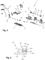
- the Figure 2 shows an exploded view of the automatic heel unit 1 in the downhill configuration in an oblique view.
- the automatic heel unit 1 is shown aligned so that the automatic heel unit 1 in the front Figure 2 is at the top left, while the automatic heel unit 1 is at the back in the Figure 2 bottom right is.
- Next are above and below the automatic heel unit 1 in the Figure 2 above and below.
- the base unit 2 comprises several elements.
- the base unit 2 thus comprises a base plate 21 which can be fastened to the ski.
- the base unit 2 further comprises a slide 22 which is mounted on the base plate 21 so as to be displaceable in the longitudinal direction of the ski.
- a longitudinal positioning arrangement is also located between the carriage 22 and the base plate 21.
- the longitudinal positioning arrangement includes, inter alia, a screw 23 which engages a half-thread on an upper side of the base plate 21, as well as a longitudinal compensation spring 24.
- the carriage 22 is also biased forward in a known manner together with the heel holder 3 by the longitudinal compensating spring 24 and can be pushed backwards against this bias in order to avoid changes in distance between the front-end automaton and the heel holder 3, which should occur when the Skis can arise to compensate.
- a vertically aligned pin 25 which is aligned concentrically with the pivot axis and which is formed from one piece together with the slide 22.
- This pin 25 is hollow on the inside and has two first recesses facing forwards and a second recess facing backwards in its lateral surface.
- a first pusher element 27 in the pin 25 is mounted on the peg 25 so as to be displaceable in the longitudinal direction of the ski
- a second pusher element 28 in the peg 25 is mounted on the peg 25 in the second recess so as to be displaceable in the longitudinal direction of the ski.
- An elastic element 26 is clamped between the first impact element 27 and the second impact element 28.
- the entire volume of the elastic element 26 is located in an inner volume of the pin 25. In other embodiments, however, there is also the possibility that, for example, only 70% or only 90% of the volume of the elastic element 26 is located in the inner volume of the pin 25.
- the elastic element 26 is a spiral spring which is aligned in the longitudinal direction of the ski. Since the elastic element 26 is clamped between the first pushing element 27 and the second pushing element 28, the elastic element 26 generates a forwardly directed first force due to which the first pushing element 27 is pushed forward. An alignment axis of the elastic element 26 aligned along the direction of the first force is thus aligned in the longitudinal direction of the ski and thus perpendicular to the pivot axis. At the same time, the elastic element 26 generates a rearwardly directed second force, as a result of which the second pushing element 28 is pressed backward. The bias of the elastic element 26 and thus a strength of the first force and a strength of the second force can be adjusted by means of an adjusting screw 35.
- the heel holder 3 is mounted on the pin 25 so as to be pivotable about the pin 25 and thus about the pivot axis.
- the heel holder 3 comprises a housing 31 which comprises two parts. These two parts of the housing 31 are screwed together in the assembled state of the automatic heel unit 1 and form a downwardly directed receptacle 32 into which the pin 25 is rotatably inserted.
- the pin 25 and the receptacle 32 thus form the radial bearing, by means of which the heel holder 3 is mounted on the base unit 2 such that it can pivot about the pivot axis relative to the base unit 2.
- the pivot axis runs concentrically through the pin 25 and through the receptacle 32.
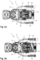
- FIGs 3a and 3b each show a plan view of a horizontally oriented cross section through the automatic heel 1 at the level of the elastic element 26, the first pushing element 27 and the second pushing element 28.
- the automatic heel 1 is shown in FIG Figure 3a shown in the downhill configuration, where the heel holder 3 is in its holding position.
- the heel holder 3 is pivoted somewhat laterally to the left, starting from its holding position, so that the holding means 4.1, 4.2, which are not visible here, point to the front left.
- the first push element 27 comprises a first positioning structure 29 on its side facing away from the elastic element 26 and thus facing forward.
- the second impact element 28 comprises a second positioning structure 30 on its side facing away from the elastic element 26 and thus facing backwards.
- a first counter-structure 33 and a second counter-structure 34 are located opposite one another on the inside of the receptacle 32. The first counter-structure 33 is thus arranged in a first radial direction from the pivot axis, while the second counter-structure 34 is arranged in a second radial direction from the pivot axis that is opposite to the first radial direction.
- the first counter-structure 33 is located at the front on the inside of the receptacle 32, while the second counter-structure 34 is located at the rear on the inside of the receptacle 32.
- the elastic element 26 is clamped between the first pushing element 27 and the second pushing element 28. As a result, the elastic element 26 generates a forwardly directed first force due to which the first pushing element 27 is pushed forward, and a rearwardly directed second force due to which the second pushing element 28 is pushed backward.
- the first pushing element 27 with the first positioning structure 29 is thus pressed against the first counter-structure 33, while the second pushing element 28 with the second positioning structure 30 is pressed against the second counter-structure 34. Since the elastic element 26 acts directly on the first pushing element 27 with the first force, the first pushing element 27 is pressed with a first pushing element force, which is the same as the first force, with the first positioning structure 29 against the first counter-structure 33.
- the automatic heel unit comprises a first deflection mechanism or a first lever mechanism which effects a deflection and / or an increase or reduction of the first force into the first impact element force.
- the automatic heel unit comprises a second deflection mechanism or a second lever mechanism which effects a deflection and / or an increase or reduction of the second force into the second impact element force.
- the first deflecting mechanism or first lever mechanism that may be present and the second deflecting mechanism or second lever mechanism that may be present can also be a combined mechanism.
- the heel holder 3 can be pivoted on both sides about the pivot axis. As already mentioned, the heel holder 3 can thus be adjusted along the adjustment path.
- the heel holder 3 is in its holding position and if the heel holder 3 is pivoted somewhat about the pivot axis starting from its holding position on one of the two possible sides, the heel holder 3 is in a first area of the adjustment path. With such a pivoting movement of the heel holder 3 within the first range of the adjustment path, the first counter structure 33 is tilted relative to the first positioning structure 29, while at the same time the second counter structure 34 is tilted relative to the second positioning structure 30.
- the heel holder 3 is moved away from its holding position, the more the first pushing element 27 is moved towards the pivot axis against the bias of the elastic element 26 due to the shape of the first positioning structure 29 and the first counter-structure 33.
- the second pushing element 28 is moved further towards the pivot axis due to the shape of the second positioning structure 30 and the second counter-structure 34 against the bias of the elastic element 26.
- the heel holder 3 is therefore pretensioned towards its holding position within the first range of the adjustment path.
- the heel holder 3 can be pivoted away on both sides against this bias.
- the heel holder 3 can be pivoted away from its holding position against the bias in the event of lateral impacts on the ski, ski binding or ski boot. If the energy of a shock exceeds a limit value, the heel holder 3 can be pivoted sufficiently far about the pivot axis so that the ski boot is released on the corresponding side by the automatic heel unit 1.
- the automatic heel unit 1 thus enables a lateral safety release.
- the heel holder 3 If the heel holder 3 is pivoted laterally away from its holding position beyond the first range of the adjustment path, then the first pushing element 27 and the second pushing element 28 are no longer moved against the bias of the elastic element 26 towards the pivot axis. Only when the heel holder 3 is pivoted further does the heel holder 3 reach a second area of the adjustment path, where the first counter structure 33 has reached the second positioning structure 30 of the second push element 28 and the second counter structure 34 has reached the first positioning structure 29 of the first push element 27 has reached.
- the first pushing element 27 and the second pushing element 28 can be moved further apart again by the pretensioned elastic element 26 with increasing pivoting movement of the heel holder 3 until the heel holder 3 has reached its walking position, where it is compared to its holding position is pivoted relative to the base unit 2 by 180 ° about the pivot axis.
- the heel holder 3 is thus biased towards its walking position within the second region of the adjustment path.
- FIGS 4a and 4b each show a view of a vertically oriented cross section running in the longitudinal direction of the ski through the automatic heel unit 1.
- the automatic heel unit 1 is shown in FIG Figure 4a shown in the departure configuration while in Figure 4b shown in the second walking configuration.
- the adjusting screw 35 can be rotated, whereby the nut 36 is moved along the adjusting screw 35 and the pretensioning of the elastic element 26 is adjusted. In this way, the energy that the automatic heel unit 1 can absorb until a lateral safety release occurs can be set.
- the pin 25 is hollow on the inside and has two first recesses oriented toward the front and a second recess oriented toward the rear in its outer surface.
- the first pusher element 27 and the second pusher element 28 extend out of the pin 25 through these recesses and can interact with their first positioning structure 29 and second positioning structure 30, as described above, with the first counter-structure 33 or with the second counter-structure 34.
- the pin 25 at its proximal end and at its distal end each have a rim that extends away from the pivot axis and overlaps the lateral surface.
- the housing 31 of the heel holder 3 engages around the upper rim and in the area of the lateral surface of the pin 25 extends somewhat towards the pivot axis to the lateral surface.
- the heel holder 3 is held on the pin 25 in the axial direction.
- the radial bearing formed from the journal 25 and the recess 32 also forms an axial bearing at the same time.
- the automatic heel unit has an axial bearing separated from the radial bearing.
- the axial bearing can be arranged in the radial direction outside or inside the radial bearing, for example, as seen from the pivot axis.
- the two holding means 4.1, 4.2 are formed by horizontally aligned pins, which point with their free ends forwards in order to engage in corresponding recesses in the heel area of the ski boot in order to lower the heel area of the ski boot Hold down position.
- the two holding means 4.1, 4.2 are pretensioned towards one another and can be pressed apart against this pretensioning, whereby the automatic heel unit 1 enables a safety release in the forward direction.
- the mechanism by which this pretension is generated is arranged in the heel holder 3 above the pin 25.
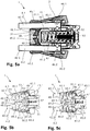
- FIGs 5a, 5b and 5c each show a bottom view of a horizontally aligned cross-section through the heel holder 3 of the automatic heel unit 1 at the level of the mechanism by which the prestress is generated with which the two holding means 4.1, 4.2 are prestressed towards one another.
- the two holding means 4.1, 4.2 are each shown with their free ends pointing to the left in the figures. If the automatic heel 1 is thus in the downhill configuration and the heel holder 3 is in its holding position and the free ends of the two holding means 4.1, 4.2 thus point forward, then the automatic heel 1 is at the front left in the illustration, while the automatic heel 1 at the back of the illustration on the right.
- the cross section shown runs through the two holding means 4.1, 4.2.
- the cross-section runs at a height slightly below the two holding means 4.1, 4.2 through the heel holder 3.
- the two holding elements 42.1, 42.2 are shown at a holding distance from one another, while the two holding elements 42.1, 42.2 in the Figure 5c are shown moved away from each other by their holding distance.
- the two holding means 4.1, 4.2 are formed by horizontally aligned pins which, in the holding position of the heel holder 3, point with their free ends forward in order to engage in corresponding recesses in the heel area of the ski boot.
- the two holding means 4.1, 4.2 or the two pins can each be divided into an arm 41.1, 41.2 and a holding element 42.1, 42.2 for holding the ski boot in the heel area of the ski boot, the respective holding element 42.1, 42.2 at a holding end of the respective Arms 41.1, 41.2 is arranged.
- the formulation also applies, according to which the two holding elements 42.1, 42.2 are each formed by a pin with its free end pointing forwards in order to engage in a recess in the heel area of the ski boot to hold the ski boot in the heel area of the ski boot.
- the two holding means 4.1, 4.2 are each pivotably mounted on the remainder of the heel holder 3 in an area of an end of the respective arm 41.1, 41.2 opposite the holding end of the respective arm 41.1, 41.2.
- the pins are each held in the area of the end of the respective arm 41.1, 41.2 opposite the holding end of the respective arm 41.1, 41.2 in the housing 31 of the heel holder 3 in the directions perpendicular to the longitudinal axis of the respective arm 41.1, 41.2.
- the pins each have a circumferential groove 44.1, 44.2 in the area of the end of the respective arm 41.1, 41.2 opposite the holding end of the respective arm 41.1, 41.2, with a vertical bolt 43.1 for each holding means 4.1, 4.2 when the automatic heel unit 1 is assembled , 43.2 is inserted in the housing 31 of the heel holder 3, which runs through the groove 44.1, 44.2 in the respective arm 41.1, 41.2 and thereby the respective holding means 4.1, 4.2 on a movement of the respective holding means 4.1, 4.2 in the longitudinal direction of the arm 41.1, 41.2 of the respective holding means 4.1, 4.2 prevents.
- the two holding means 4.1, 4.2 each in a region of the end of the respective arm 42.1, 42.2 opposite the holding end of the respective arm 41.1, 41.2 mounted pivotably relative to one another on the remaining heel holder 3, whereby a distance between the two holding elements 42.1, 42.2 can be changed.
- the two holding means 4.1, 4.2 are each mounted on the remaining heel holder 3 so that they can rotate about the longitudinal axis of the respective arm 41.1, 41.2.
- the automatic heel unit 1 further comprises a transmission element 46 arranged in the housing 31 of the heel holder 3 and an elastic pretensioning element 47 also arranged in the housing 31 of the heel holder 3
- Holding means 4.1, 4.2 each have a sleeve 45.1, 45.2.
- the elastic preloading element 47 is designed in the form of a spiral spring and is supported at a first end against a nut 52. This nut 52 is screwed onto a screw 53, which in turn is supported on an inner side of the housing 31 of the heel holder 3. A position of the first end of the elastic prestressing element 47 within the housing 31 of the heel holder 3 can thus be adjusted by turning the screw 53. This enables a pre-tensioning of the elastic pre-tensioning element 47 to be adjusted because the elastic pre-tensioning element 47 is also supported at a second end against the transmission element 46.
- the elastic prestressing element 47 therefore presses against the transmission element 46 with a prestressing force dependent on the prestressing of the elastic prestressing element 47. Due to this prestressing force, the transmission element 46 acts with the prestressing force on the two sleeves 45.1, 45.2.
- the two sleeves 45.1, 45.2 are each mounted on the arm 41.1, 41.2 of the respective holding means 4.1, 4.2 in a region of the holding end of the respective arm 41.1, 41.2 in the longitudinal direction of the respective arm 41.1, 41.2.
- the two sleeves 45.1, 45.2 are mounted horizontally in the transverse direction of the ski in the housing 31 of the heel holder 3. Because of this mounting of the sleeves 45.1, 45.2 and because of the pivoting mounting of the arms 41.1, 41.2, the two holding means 4.1, 4.2 are mounted so as to be movable relative to one another in a horizontal plane.
- both sleeves 45.1, 45.2 each have a first control structure 48.1, 48.2 facing the holding element 42.1, 42.2 of the respective holding means 4.1, 4.2.
- These first control structures 48.1, 48.2 are inclined with respect to the longitudinal directions of the arms 41.1, 41.2 and run towards the center of the ski in the direction of the holding elements 42.1, 42.2.
- first control structures 48.1, 48.2 face first counter-control structures 49.1, 49.2, which are arranged on an inside of a wall of the housing 31 of the heel holder 3 facing the holding elements 42.1, 42.2 and which are also inclined to the longitudinal directions of the arms 41.1, 41.2 and to the center of the ski extend towards the retaining elements 42.1, 42.2. Since the elastic prestressing element 47 is aligned parallel to the arms 41.1, 41.2, the elastic prestressing element 47 presses the transmission element 46 with the prestressing force against the two sleeves 45.1, 45.2, whereby the sleeves 45.1, 45.2 with their first control structures 48.1, 48.2 against the first Control counter structures 49.1, 49.2 on the housing 31 of the heel holder 3 are pressed.
- the two sleeves 45.1, 45.2 are pretensioned towards one another.
- the two holding ends of the arms 41.1, 41.2 are biased towards each other with the sleeves 45.1, 45.2, whereby the two holding elements 42.1, 42.2 are biased towards each other with the holding force to their holding distance so that the two holding means 4.1, 4.2 in the holding configuration of Automatic heel units 1 interact with the heel area of the ski boot held in the ski binding and can hold down the heel area of the ski boot in the lowered position and thus the automatic heel unit 1 enables a safety release in the forward direction.
- the two sleeves 45.1, 45.2 each have a second control structure 50.1, 50.2 facing away from the holding element 42.1, 42.2 of the respective holding means 4.1, 4.2.
- These second control structures 50.1, 50.2 are inclined with respect to the longitudinal directions of the arms 41.1, 41.2 and run away from the holding elements 42.1, 42.2 towards the center of the ski.
- These second control structures 50.1, 50.2 face second counterpart control structures 51.1, 51.2, which are arranged on the transmission element 47 and also opposite one another are inclined in the longitudinal directions of the arms 41.1, 41.2 and run away from the holding elements 42.1, 42.2 towards the center of the ski.
- the two sleeves 45.1, 45.2 are thus not only through an interaction of the first control structures 48.1, 48.2 with the first counter control structures 49.1, 49.2, but also through an interaction of the second control structures 50.1, 50.2 with the second counter control structures 51.1, 51.2 biased towards one another.
- the holding ends of the arms 41.1, 41.2 are thus pretensioned towards one another, whereby the two holding elements 42.1, 42.2 are pretensioned towards one another with the holding force to their holding distance.
- the two holding elements 42.1, 42.2 are accordingly located as in FIG Figures 5a and 5b shown in their holding distance from one another when the two holding elements 42.1, 42.2 are not pressed apart by an external force.
- the two holding elements 42.1, 42.2 are not only pretensioned with the holding force to their holding distance, but are also as in FIG Figure 5c shown against the holding force of their holding distance apart and thus movable away from their holding distance.
- the two holding elements 42.1, 42.2 for entry into the automatic heel unit 1 can be moved apart from their holding distance when a ski boot for entry into the automatic heel unit 1 is guided from top to bottom over the holding means 4.1, 4.2.
- the two holding elements 42.1, 42.2 can also be moved apart from their holding distance against the holding force, if an upward force on the ski boot or a downward force on the automatic heel unit 1 or the ski is sufficiently great to move the ski boot to be released from the automatic heel 1 for a safety release in the forward direction.
- a release value of this safety release can be set in the forward direction because the pretensioning force and thus also the holding force can be adjusted by adjusting the screw 53.
- Both entry into the automatic heel unit 1 and a safety release in the forward direction are also optimally controlled because the arms 41.1, 41.2 of the two holding means 4.1, 4.2 are each rotatable about the longitudinal axis of the respective arm 41.1, 41.2 remaining heel holder 3 and rotatably mounted in the respective sleeve 45.1, 45.2, whereby frictional resistance of the ski boot on the holding means 4.1, 4.2 are minimized.
- FIG. 6 shows a simplified schematic side view of a further automatic heel 101 according to the invention.
- This automatic heel 101 is essentially the same as that in FIG Figures 1a to 5
- the automatic heel unit 1 shown is constructed and comprises a base unit 102 for attachment to the surface of a ski, a heel holder 103 with at least one holding means 104 and a radial bearing through which the heel holder 103 can be pivoted about a vertically oriented, geometric pivot axis relative to the base unit 102 on the base unit 102 is stored.
- the automatic heel unit 101 also comprises an elastic element 126 arranged in the pin 125, the alignment axis of which is aligned perpendicular to the pivot axis.
- a first pusher element 127 and a second pusher element 128 are again mounted displaceably in the pin 125, the elastic element 126 being clamped between the first pusher element 127 and the second pusher element 128.
- the pin 125 is arranged on the heel holder 103, while the receptacle 132 is arranged on the base unit 102.
- the first counter structure 133 and the second counter structure 134 are assigned to the heel holder 103, while the first positioning structure 129 is still arranged on the first push element 127 and the second positioning structure 130 is still arranged on the second push element 128.
- the base unit can be designed differently, for example in one piece.
- the heel holder can also be designed differently.
- a jaw can also be used as the holding means.
- the radial bearing also forms an axial bearing.
- the automatic heel unit can also comprise an axial bearing that is embodied separately from the radial bearing.
- an automatic heel unit which has a compact design and at the same time enables the heel holder to be stably supported on the base element.
Landscapes
- Footwear And Its Accessory, Manufacturing Method And Apparatuses (AREA)
Priority Applications (1)
| Application Number | Priority Date | Filing Date | Title |
|---|---|---|---|
| EP20156651.0A EP3702005B1 (fr) | 2018-06-14 | 2018-06-14 | Talonnière |
Applications Claiming Priority (2)
| Application Number | Priority Date | Filing Date | Title |
|---|---|---|---|
| EP20156651.0A EP3702005B1 (fr) | 2018-06-14 | 2018-06-14 | Talonnière |
| EP18177784.8A EP3581248A1 (fr) | 2018-06-14 | 2018-06-14 | Talonnière |
Related Parent Applications (1)
| Application Number | Title | Priority Date | Filing Date |
|---|---|---|---|
| EP18177784.8A Division EP3581248A1 (fr) | 2018-06-14 | 2018-06-14 | Talonnière |
Publications (2)
| Publication Number | Publication Date |
|---|---|
| EP3702005A1 true EP3702005A1 (fr) | 2020-09-02 |
| EP3702005B1 EP3702005B1 (fr) | 2024-07-03 |
Family
ID=62636116
Family Applications (2)
| Application Number | Title | Priority Date | Filing Date |
|---|---|---|---|
| EP18177784.8A Withdrawn EP3581248A1 (fr) | 2018-06-14 | 2018-06-14 | Talonnière |
| EP20156651.0A Active EP3702005B1 (fr) | 2018-06-14 | 2018-06-14 | Talonnière |
Family Applications Before (1)
| Application Number | Title | Priority Date | Filing Date |
|---|---|---|---|
| EP18177784.8A Withdrawn EP3581248A1 (fr) | 2018-06-14 | 2018-06-14 | Talonnière |
Country Status (1)
| Country | Link |
|---|---|
| EP (2) | EP3581248A1 (fr) |
Cited By (3)
| Publication number | Priority date | Publication date | Assignee | Title |
|---|---|---|---|---|
| EP4272847A3 (fr) * | 2022-05-02 | 2023-11-29 | MARKER Deutschland GmbH | Talonnière à resistance pour déclenchement vertical réglable |
| IT202200014266A1 (it) * | 2022-07-06 | 2024-01-06 | Atk Sports S R L | Talloniera per un attacco da sci |
| EP4574224A1 (fr) | 2023-12-21 | 2025-06-25 | Wehrli Maschinenbau AG | Talonniere pour une fixation de planche de glisse et planche de glisse |
Families Citing this family (5)
| Publication number | Priority date | Publication date | Assignee | Title |
|---|---|---|---|---|
| AT523493A1 (de) * | 2020-01-31 | 2021-08-15 | Tyrolia Tech Gmbh | Fersenbacken für eine Abfahrts- oder eine kombinierte Abfahrts- und Tourenbindung |
| DE102020203271A1 (de) * | 2020-03-13 | 2021-09-16 | Salewa Sport Ag | Ferseneinheit mit auslöse- und verstellmechanismus |
| DE102022110765A1 (de) * | 2022-05-02 | 2023-11-02 | Marker Deutschland Gmbh | Fersenhalter mit gerader Führungsbahn der Halteelemente bei Vertikalauslösung |
| US20240325864A1 (en) * | 2023-04-01 | 2024-10-03 | Cameron Allan Shute | Ski Binding Heel Unit |
| DE102024129167A1 (de) * | 2024-10-09 | 2026-04-09 | Salewa Sport Ag | Ferseneinheit für eine Tourenbindung |
Citations (7)
| Publication number | Priority date | Publication date | Assignee | Title |
|---|---|---|---|---|
| EP0199098A2 (fr) | 1985-03-25 | 1986-10-29 | Fritz Dipl.-Ing. Barthel | Fixation pour ski de randonnée |
| EP0754079B1 (fr) | 1995-02-01 | 1999-04-28 | Fritschi Ag, Apparatebau | Fixation de ski |
| WO2009105866A1 (fr) * | 2008-02-29 | 2009-09-03 | G3 Genuine Guide Gear Inc. | Unité talon pour fixation de randonnée en montagne |
| WO2012024809A1 (fr) | 2010-08-27 | 2012-03-01 | Fritschi Ag - Swiss Bindings | Fixation de ski de randonnée à talonnière comportant une zone de glissement dynamique |
| WO2012156899A1 (fr) * | 2011-05-13 | 2012-11-22 | Tasci S.R.L. | Dispositif de fixation de ski pour fixer une chaussure de ski sur un ski de descente ou analogue |
| EP3167943A1 (fr) | 2015-11-12 | 2017-05-17 | Fritschi AG - Swiss Bindings | Talonniere comprenant une structure d'appui de talon |
| FR3043565A1 (fr) * | 2015-11-17 | 2017-05-19 | The M Equipment | Talonniere pour fixation de ski, fixation et ski correspondants |
Family Cites Families (1)
| Publication number | Priority date | Publication date | Assignee | Title |
|---|---|---|---|---|
| DE102004005025A1 (de) * | 2004-01-30 | 2005-08-18 | Marker Deutschland Gmbh | Auslösbare Skibindung |
-
2018
- 2018-06-14 EP EP18177784.8A patent/EP3581248A1/fr not_active Withdrawn
- 2018-06-14 EP EP20156651.0A patent/EP3702005B1/fr active Active
Patent Citations (7)
| Publication number | Priority date | Publication date | Assignee | Title |
|---|---|---|---|---|
| EP0199098A2 (fr) | 1985-03-25 | 1986-10-29 | Fritz Dipl.-Ing. Barthel | Fixation pour ski de randonnée |
| EP0754079B1 (fr) | 1995-02-01 | 1999-04-28 | Fritschi Ag, Apparatebau | Fixation de ski |
| WO2009105866A1 (fr) * | 2008-02-29 | 2009-09-03 | G3 Genuine Guide Gear Inc. | Unité talon pour fixation de randonnée en montagne |
| WO2012024809A1 (fr) | 2010-08-27 | 2012-03-01 | Fritschi Ag - Swiss Bindings | Fixation de ski de randonnée à talonnière comportant une zone de glissement dynamique |
| WO2012156899A1 (fr) * | 2011-05-13 | 2012-11-22 | Tasci S.R.L. | Dispositif de fixation de ski pour fixer une chaussure de ski sur un ski de descente ou analogue |
| EP3167943A1 (fr) | 2015-11-12 | 2017-05-17 | Fritschi AG - Swiss Bindings | Talonniere comprenant une structure d'appui de talon |
| FR3043565A1 (fr) * | 2015-11-17 | 2017-05-19 | The M Equipment | Talonniere pour fixation de ski, fixation et ski correspondants |
Cited By (5)
| Publication number | Priority date | Publication date | Assignee | Title |
|---|---|---|---|---|
| EP4272847A3 (fr) * | 2022-05-02 | 2023-11-29 | MARKER Deutschland GmbH | Talonnière à resistance pour déclenchement vertical réglable |
| IT202200014266A1 (it) * | 2022-07-06 | 2024-01-06 | Atk Sports S R L | Talloniera per un attacco da sci |
| EP4302844A1 (fr) * | 2022-07-06 | 2024-01-10 | Atk Sports S.R.L. | Talonnière de fixation de ski |
| EP4574224A1 (fr) | 2023-12-21 | 2025-06-25 | Wehrli Maschinenbau AG | Talonniere pour une fixation de planche de glisse et planche de glisse |
| WO2025132937A1 (fr) | 2023-12-21 | 2025-06-26 | Wehrli Maschinenbau Ag | Unité de placement de talon pour une fixation de planche de glisse et planche de glisse |
Also Published As
| Publication number | Publication date |
|---|---|
| EP3702005B1 (fr) | 2024-07-03 |
| EP3581248A1 (fr) | 2019-12-18 |
Similar Documents
| Publication | Publication Date | Title |
|---|---|---|
| EP3702005B1 (fr) | Talonnière | |
| EP2608853B1 (fr) | Butée arrière de randonnee avec plage de glissement dynamique | |
| EP2574379B1 (fr) | Automate avant | |
| EP2659939B1 (fr) | Unité de talon pour une fixation de ski de randonnée | |
| EP3566754B1 (fr) | Butée avant de fixation de ski | |
| DE1960002C3 (de) | Auslösende Skibindung mit einer verschwenkbaren Trittplatte | |
| EP2705883B1 (fr) | Automate de talon pour une fixation de ski | |
| DE202009019128U1 (de) | Zeheneinheit für Tourenskibindung | |
| DE102012208915B4 (de) | Ferseneinheit mit Steighilfe und Bremsanordnung | |
| EP3928842B1 (fr) | Unité avant pour une fixation de randonnée | |
| EP3053632B1 (fr) | Talonnière | |
| EP3345659B1 (fr) | Talonnière automatique pour une fixation de ski | |
| EP2813268A1 (fr) | Automate avant | |
| EP3120903B1 (fr) | Talonnière | |
| EP3195906B1 (fr) | Talonniere ayant une configuration de marche | |
| DE102013224574B4 (de) | Ferseneinheit für eine Tourenbindung und Tourenbindung | |
| EP3167943B1 (fr) | Talonniere comprenant une structure d'appui de talon | |
| EP3332843B1 (fr) | Unité de talon pour une fixation de planche de glisse dotée d'un systeme de frein | |
| CH706664B1 (de) | Skibindung. | |
| EP2965791B1 (fr) | Unité de positionnement automatique d'avant de chaussure de skis pour fixation à ergots | |
| EP3851174A1 (fr) | Butée avant pour une fixation de ski | |
| EP3103525B1 (fr) | Talonnière | |
| EP3266504A1 (fr) | Fixation de ski | |
| CH705586A2 (de) | Frontautomat. | |
| DE3784405T2 (de) | Skibindung. |
Legal Events
| Date | Code | Title | Description |
|---|---|---|---|
| PUAI | Public reference made under article 153(3) epc to a published international application that has entered the european phase |
Free format text: ORIGINAL CODE: 0009012 |
|
| STAA | Information on the status of an ep patent application or granted ep patent |
Free format text: STATUS: THE APPLICATION HAS BEEN PUBLISHED |
|
| AC | Divisional application: reference to earlier application |
Ref document number: 3581248 Country of ref document: EP Kind code of ref document: P |
|
| AK | Designated contracting states |
Kind code of ref document: A1 Designated state(s): AL AT BE BG CH CY CZ DE DK EE ES FI FR GB GR HR HU IE IS IT LI LT LU LV MC MK MT NL NO PL PT RO RS SE SI SK SM TR |
|
| AX | Request for extension of the european patent |
Extension state: BA ME |
|
| STAA | Information on the status of an ep patent application or granted ep patent |
Free format text: STATUS: REQUEST FOR EXAMINATION WAS MADE |
|
| 17P | Request for examination filed |
Effective date: 20210217 |
|
| RBV | Designated contracting states (corrected) |
Designated state(s): AL AT BE BG CH CY CZ DE DK EE ES FI FR GB GR HR HU IE IS IT LI LT LU LV MC MK MT NL NO PL PT RO RS SE SI SK SM TR |
|
| GRAP | Despatch of communication of intention to grant a patent |
Free format text: ORIGINAL CODE: EPIDOSNIGR1 |
|
| STAA | Information on the status of an ep patent application or granted ep patent |
Free format text: STATUS: GRANT OF PATENT IS INTENDED |
|
| INTG | Intention to grant announced |
Effective date: 20240307 |
|
| GRAS | Grant fee paid |
Free format text: ORIGINAL CODE: EPIDOSNIGR3 |
|
| GRAA | (expected) grant |
Free format text: ORIGINAL CODE: 0009210 |
|
| STAA | Information on the status of an ep patent application or granted ep patent |
Free format text: STATUS: THE PATENT HAS BEEN GRANTED |
|
| AC | Divisional application: reference to earlier application |
Ref document number: 3581248 Country of ref document: EP Kind code of ref document: P |
|
| AK | Designated contracting states |
Kind code of ref document: B1 Designated state(s): AL AT BE BG CH CY CZ DE DK EE ES FI FR GB GR HR HU IE IS IT LI LT LU LV MC MK MT NL NO PL PT RO RS SE SI SK SM TR |
|
| REG | Reference to a national code |
Ref country code: CH Ref legal event code: EP |
|
| REG | Reference to a national code |
Ref country code: DE Ref legal event code: R096 Ref document number: 502018014829 Country of ref document: DE |
|
| REG | Reference to a national code |
Ref country code: LT Ref legal event code: MG9D |
|
| REG | Reference to a national code |
Ref country code: NL Ref legal event code: MP Effective date: 20240703 |
|
| PG25 | Lapsed in a contracting state [announced via postgrant information from national office to epo] |
Ref country code: PT Free format text: LAPSE BECAUSE OF FAILURE TO SUBMIT A TRANSLATION OF THE DESCRIPTION OR TO PAY THE FEE WITHIN THE PRESCRIBED TIME-LIMIT Effective date: 20241104 |
|
| PG25 | Lapsed in a contracting state [announced via postgrant information from national office to epo] |
Ref country code: NL Free format text: LAPSE BECAUSE OF FAILURE TO SUBMIT A TRANSLATION OF THE DESCRIPTION OR TO PAY THE FEE WITHIN THE PRESCRIBED TIME-LIMIT Effective date: 20240703 |
|
| PG25 | Lapsed in a contracting state [announced via postgrant information from national office to epo] |
Ref country code: PT Free format text: LAPSE BECAUSE OF FAILURE TO SUBMIT A TRANSLATION OF THE DESCRIPTION OR TO PAY THE FEE WITHIN THE PRESCRIBED TIME-LIMIT Effective date: 20241104 Ref country code: NL Free format text: LAPSE BECAUSE OF FAILURE TO SUBMIT A TRANSLATION OF THE DESCRIPTION OR TO PAY THE FEE WITHIN THE PRESCRIBED TIME-LIMIT Effective date: 20240703 |
|
| PG25 | Lapsed in a contracting state [announced via postgrant information from national office to epo] |
Ref country code: NO Free format text: LAPSE BECAUSE OF FAILURE TO SUBMIT A TRANSLATION OF THE DESCRIPTION OR TO PAY THE FEE WITHIN THE PRESCRIBED TIME-LIMIT Effective date: 20241003 |
|
| PG25 | Lapsed in a contracting state [announced via postgrant information from national office to epo] |
Ref country code: GR Free format text: LAPSE BECAUSE OF FAILURE TO SUBMIT A TRANSLATION OF THE DESCRIPTION OR TO PAY THE FEE WITHIN THE PRESCRIBED TIME-LIMIT Effective date: 20241004 Ref country code: FI Free format text: LAPSE BECAUSE OF FAILURE TO SUBMIT A TRANSLATION OF THE DESCRIPTION OR TO PAY THE FEE WITHIN THE PRESCRIBED TIME-LIMIT Effective date: 20240703 Ref country code: PL Free format text: LAPSE BECAUSE OF FAILURE TO SUBMIT A TRANSLATION OF THE DESCRIPTION OR TO PAY THE FEE WITHIN THE PRESCRIBED TIME-LIMIT Effective date: 20240703 |
|
| PG25 | Lapsed in a contracting state [announced via postgrant information from national office to epo] |
Ref country code: BG Free format text: LAPSE BECAUSE OF FAILURE TO SUBMIT A TRANSLATION OF THE DESCRIPTION OR TO PAY THE FEE WITHIN THE PRESCRIBED TIME-LIMIT Effective date: 20240703 |
|
| PG25 | Lapsed in a contracting state [announced via postgrant information from national office to epo] |
Ref country code: LV Free format text: LAPSE BECAUSE OF FAILURE TO SUBMIT A TRANSLATION OF THE DESCRIPTION OR TO PAY THE FEE WITHIN THE PRESCRIBED TIME-LIMIT Effective date: 20240703 |
|
| PG25 | Lapsed in a contracting state [announced via postgrant information from national office to epo] |
Ref country code: IS Free format text: LAPSE BECAUSE OF FAILURE TO SUBMIT A TRANSLATION OF THE DESCRIPTION OR TO PAY THE FEE WITHIN THE PRESCRIBED TIME-LIMIT Effective date: 20241103 |
|
| PG25 | Lapsed in a contracting state [announced via postgrant information from national office to epo] |
Ref country code: HR Free format text: LAPSE BECAUSE OF FAILURE TO SUBMIT A TRANSLATION OF THE DESCRIPTION OR TO PAY THE FEE WITHIN THE PRESCRIBED TIME-LIMIT Effective date: 20240703 Ref country code: CZ Free format text: LAPSE BECAUSE OF FAILURE TO SUBMIT A TRANSLATION OF THE DESCRIPTION OR TO PAY THE FEE WITHIN THE PRESCRIBED TIME-LIMIT Effective date: 20240703 |
|
| PG25 | Lapsed in a contracting state [announced via postgrant information from national office to epo] |
Ref country code: ES Free format text: LAPSE BECAUSE OF FAILURE TO SUBMIT A TRANSLATION OF THE DESCRIPTION OR TO PAY THE FEE WITHIN THE PRESCRIBED TIME-LIMIT Effective date: 20240703 Ref country code: RS Free format text: LAPSE BECAUSE OF FAILURE TO SUBMIT A TRANSLATION OF THE DESCRIPTION OR TO PAY THE FEE WITHIN THE PRESCRIBED TIME-LIMIT Effective date: 20241003 |
|
| PG25 | Lapsed in a contracting state [announced via postgrant information from national office to epo] |
Ref country code: RS Free format text: LAPSE BECAUSE OF FAILURE TO SUBMIT A TRANSLATION OF THE DESCRIPTION OR TO PAY THE FEE WITHIN THE PRESCRIBED TIME-LIMIT Effective date: 20241003 Ref country code: PL Free format text: LAPSE BECAUSE OF FAILURE TO SUBMIT A TRANSLATION OF THE DESCRIPTION OR TO PAY THE FEE WITHIN THE PRESCRIBED TIME-LIMIT Effective date: 20240703 Ref country code: NO Free format text: LAPSE BECAUSE OF FAILURE TO SUBMIT A TRANSLATION OF THE DESCRIPTION OR TO PAY THE FEE WITHIN THE PRESCRIBED TIME-LIMIT Effective date: 20241003 Ref country code: LV Free format text: LAPSE BECAUSE OF FAILURE TO SUBMIT A TRANSLATION OF THE DESCRIPTION OR TO PAY THE FEE WITHIN THE PRESCRIBED TIME-LIMIT Effective date: 20240703 Ref country code: IS Free format text: LAPSE BECAUSE OF FAILURE TO SUBMIT A TRANSLATION OF THE DESCRIPTION OR TO PAY THE FEE WITHIN THE PRESCRIBED TIME-LIMIT Effective date: 20241103 Ref country code: HR Free format text: LAPSE BECAUSE OF FAILURE TO SUBMIT A TRANSLATION OF THE DESCRIPTION OR TO PAY THE FEE WITHIN THE PRESCRIBED TIME-LIMIT Effective date: 20240703 Ref country code: GR Free format text: LAPSE BECAUSE OF FAILURE TO SUBMIT A TRANSLATION OF THE DESCRIPTION OR TO PAY THE FEE WITHIN THE PRESCRIBED TIME-LIMIT Effective date: 20241004 Ref country code: FI Free format text: LAPSE BECAUSE OF FAILURE TO SUBMIT A TRANSLATION OF THE DESCRIPTION OR TO PAY THE FEE WITHIN THE PRESCRIBED TIME-LIMIT Effective date: 20240703 Ref country code: ES Free format text: LAPSE BECAUSE OF FAILURE TO SUBMIT A TRANSLATION OF THE DESCRIPTION OR TO PAY THE FEE WITHIN THE PRESCRIBED TIME-LIMIT Effective date: 20240703 Ref country code: CZ Free format text: LAPSE BECAUSE OF FAILURE TO SUBMIT A TRANSLATION OF THE DESCRIPTION OR TO PAY THE FEE WITHIN THE PRESCRIBED TIME-LIMIT Effective date: 20240703 Ref country code: BG Free format text: LAPSE BECAUSE OF FAILURE TO SUBMIT A TRANSLATION OF THE DESCRIPTION OR TO PAY THE FEE WITHIN THE PRESCRIBED TIME-LIMIT Effective date: 20240703 |
|
| REG | Reference to a national code |
Ref country code: DE Ref legal event code: R097 Ref document number: 502018014829 Country of ref document: DE |
|
| PG25 | Lapsed in a contracting state [announced via postgrant information from national office to epo] |
Ref country code: SM Free format text: LAPSE BECAUSE OF FAILURE TO SUBMIT A TRANSLATION OF THE DESCRIPTION OR TO PAY THE FEE WITHIN THE PRESCRIBED TIME-LIMIT Effective date: 20240703 Ref country code: RO Free format text: LAPSE BECAUSE OF FAILURE TO SUBMIT A TRANSLATION OF THE DESCRIPTION OR TO PAY THE FEE WITHIN THE PRESCRIBED TIME-LIMIT Effective date: 20240703 Ref country code: DK Free format text: LAPSE BECAUSE OF FAILURE TO SUBMIT A TRANSLATION OF THE DESCRIPTION OR TO PAY THE FEE WITHIN THE PRESCRIBED TIME-LIMIT Effective date: 20240703 |
|
| PG25 | Lapsed in a contracting state [announced via postgrant information from national office to epo] |
Ref country code: EE Free format text: LAPSE BECAUSE OF FAILURE TO SUBMIT A TRANSLATION OF THE DESCRIPTION OR TO PAY THE FEE WITHIN THE PRESCRIBED TIME-LIMIT Effective date: 20240703 |
|
| PG25 | Lapsed in a contracting state [announced via postgrant information from national office to epo] |
Ref country code: SK Free format text: LAPSE BECAUSE OF FAILURE TO SUBMIT A TRANSLATION OF THE DESCRIPTION OR TO PAY THE FEE WITHIN THE PRESCRIBED TIME-LIMIT Effective date: 20240703 |
|
| PLBE | No opposition filed within time limit |
Free format text: ORIGINAL CODE: 0009261 |
|
| STAA | Information on the status of an ep patent application or granted ep patent |
Free format text: STATUS: NO OPPOSITION FILED WITHIN TIME LIMIT |
|
| 26N | No opposition filed |
Effective date: 20250404 |
|
| PGFP | Annual fee paid to national office [announced via postgrant information from national office to epo] |
Ref country code: DE Payment date: 20250618 Year of fee payment: 8 |
|
| PGFP | Annual fee paid to national office [announced via postgrant information from national office to epo] |
Ref country code: FR Payment date: 20250626 Year of fee payment: 8 |
|
| PGFP | Annual fee paid to national office [announced via postgrant information from national office to epo] |
Ref country code: AT Payment date: 20250620 Year of fee payment: 8 |
|
| PG25 | Lapsed in a contracting state [announced via postgrant information from national office to epo] |
Ref country code: SE Free format text: LAPSE BECAUSE OF FAILURE TO SUBMIT A TRANSLATION OF THE DESCRIPTION OR TO PAY THE FEE WITHIN THE PRESCRIBED TIME-LIMIT Effective date: 20240703 |
|
| PGFP | Annual fee paid to national office [announced via postgrant information from national office to epo] |
Ref country code: IT Payment date: 20250624 Year of fee payment: 8 |
|
| PGFP | Annual fee paid to national office [announced via postgrant information from national office to epo] |
Ref country code: CH Payment date: 20250701 Year of fee payment: 8 |
|
| PG25 | Lapsed in a contracting state [announced via postgrant information from national office to epo] |
Ref country code: MC Free format text: LAPSE BECAUSE OF FAILURE TO SUBMIT A TRANSLATION OF THE DESCRIPTION OR TO PAY THE FEE WITHIN THE PRESCRIBED TIME-LIMIT Effective date: 20240703 |
|
| PG25 | Lapsed in a contracting state [announced via postgrant information from national office to epo] |
Ref country code: LU Free format text: LAPSE BECAUSE OF NON-PAYMENT OF DUE FEES Effective date: 20250614 |
|
| GBPC | Gb: european patent ceased through non-payment of renewal fee |
Effective date: 20250614 |
|
| REG | Reference to a national code |
Ref country code: BE Ref legal event code: MM Effective date: 20250630 |
|
| PG25 | Lapsed in a contracting state [announced via postgrant information from national office to epo] |
Ref country code: GB Free format text: LAPSE BECAUSE OF NON-PAYMENT OF DUE FEES Effective date: 20250614 |
|
| PG25 | Lapsed in a contracting state [announced via postgrant information from national office to epo] |
Ref country code: IE Free format text: LAPSE BECAUSE OF NON-PAYMENT OF DUE FEES Effective date: 20250614 |
|
| PG25 | Lapsed in a contracting state [announced via postgrant information from national office to epo] |
Ref country code: BE Free format text: LAPSE BECAUSE OF NON-PAYMENT OF DUE FEES Effective date: 20250630 |