EP3702006A1 - Skateboard pourvu de mécanisme de direction - Google Patents
Skateboard pourvu de mécanisme de direction Download PDFInfo
- Publication number
- EP3702006A1 EP3702006A1 EP20000084.2A EP20000084A EP3702006A1 EP 3702006 A1 EP3702006 A1 EP 3702006A1 EP 20000084 A EP20000084 A EP 20000084A EP 3702006 A1 EP3702006 A1 EP 3702006A1
- Authority
- EP
- European Patent Office
- Prior art keywords
- skateboard
- standing
- wheel axles
- skateboard according
- boards
- Prior art date
- Legal status (The legal status is an assumption and is not a legal conclusion. Google has not performed a legal analysis and makes no representation as to the accuracy of the status listed.)
- Withdrawn
Links
- 239000000853 adhesive Substances 0.000 claims description 4
- 230000001070 adhesive effect Effects 0.000 claims description 4
- 239000004033 plastic Substances 0.000 description 4
- 229920003023 plastic Polymers 0.000 description 3
- 229930040373 Paraformaldehyde Natural products 0.000 description 2
- 239000000463 material Substances 0.000 description 2
- 229920003229 poly(methyl methacrylate) Polymers 0.000 description 2
- 239000004926 polymethyl methacrylate Substances 0.000 description 2
- 229920006324 polyoxymethylene Polymers 0.000 description 2
- 208000027418 Wounds and injury Diseases 0.000 description 1
- 239000011324 bead Substances 0.000 description 1
- 238000010276 construction Methods 0.000 description 1
- 230000006378 damage Effects 0.000 description 1
- 238000011161 development Methods 0.000 description 1
- 230000018109 developmental process Effects 0.000 description 1
- 208000014674 injury Diseases 0.000 description 1
- 238000004519 manufacturing process Methods 0.000 description 1
- 239000002184 metal Substances 0.000 description 1
- 239000011120 plywood Substances 0.000 description 1
- -1 polyoxymethylene Polymers 0.000 description 1
- 230000002787 reinforcement Effects 0.000 description 1
- 238000005096 rolling process Methods 0.000 description 1
Images




Classifications
-
- A—HUMAN NECESSITIES
- A63—SPORTS; GAMES; AMUSEMENTS
- A63C—SKATES; SKIS; ROLLER SKATES; DESIGN OR LAYOUT OF COURTS, RINKS OR THE LIKE
- A63C17/00—Roller skates; Skate-boards
- A63C17/01—Skateboards
- A63C17/011—Skateboards with steering mechanisms
- A63C17/012—Skateboards with steering mechanisms with a truck, i.e. with steering mechanism comprising an inclined geometrical axis to convert lateral tilting of the board in steering of the wheel axis
-
- A—HUMAN NECESSITIES
- A63—SPORTS; GAMES; AMUSEMENTS
- A63C—SKATES; SKIS; ROLLER SKATES; DESIGN OR LAYOUT OF COURTS, RINKS OR THE LIKE
- A63C17/00—Roller skates; Skate-boards
- A63C17/04—Roller skates; Skate-boards with wheels arranged otherwise than in two pairs
- A63C17/06—Roller skates; Skate-boards with wheels arranged otherwise than in two pairs single-track type
-
- A—HUMAN NECESSITIES
- A63—SPORTS; GAMES; AMUSEMENTS
- A63C—SKATES; SKIS; ROLLER SKATES; DESIGN OR LAYOUT OF COURTS, RINKS OR THE LIKE
- A63C17/00—Roller skates; Skate-boards
- A63C17/01—Skateboards
- A63C17/014—Wheel arrangements
- A63C17/015—Wheel arrangements with wheels arranged in two pairs
-
- A—HUMAN NECESSITIES
- A63—SPORTS; GAMES; AMUSEMENTS
- A63C—SKATES; SKIS; ROLLER SKATES; DESIGN OR LAYOUT OF COURTS, RINKS OR THE LIKE
- A63C17/00—Roller skates; Skate-boards
- A63C17/10—Roller skates; Skate-boards with endless tracks
-
- A—HUMAN NECESSITIES
- A63—SPORTS; GAMES; AMUSEMENTS
- A63C—SKATES; SKIS; ROLLER SKATES; DESIGN OR LAYOUT OF COURTS, RINKS OR THE LIKE
- A63C17/00—Roller skates; Skate-boards
- A63C17/12—Roller skates; Skate-boards with driving mechanisms
-
- A—HUMAN NECESSITIES
- A63—SPORTS; GAMES; AMUSEMENTS
- A63C—SKATES; SKIS; ROLLER SKATES; DESIGN OR LAYOUT OF COURTS, RINKS OR THE LIKE
- A63C17/00—Roller skates; Skate-boards
- A63C17/22—Wheels for roller skates
- A63C17/226—Wheel mounting, i.e. arrangement connecting wheel and axle mount
-
- A—HUMAN NECESSITIES
- A63—SPORTS; GAMES; AMUSEMENTS
- A63C—SKATES; SKIS; ROLLER SKATES; DESIGN OR LAYOUT OF COURTS, RINKS OR THE LIKE
- A63C2203/00—Special features of skates, skis, roller-skates, snowboards and courts
- A63C2203/12—Electrically powered or heated
Definitions
- the invention relates to a skateboard according to the preamble of patent claim 1.
- skateboards or roller boards using bearing blocks, which also include the steering gear and each have a rubber buffer arrangement in such a way that when tilting or inclining the standing board about the longitudinal axis to control the roller board, pivoting in opposite directions Wheel axles are made around a vertical axis.
- EP 0 620 031 B1 discloses a roller board with a standing board forming a standing surface for a user, with two wheel axles on each of which at least two wheels are rotatably mounted, and with a bracket for connecting the wheel axles to the standing board.
- the known roller board has steering gear to pivot the wheel axles for steering by tilting the standing board about its longitudinal axis from a starting position perpendicular to the longitudinal axis about a vertical axis; it is also provided that the wheel axles are arranged above the standing board or.
- the object of the invention is to create a skateboard which is suitable for driving on level ground and which has driving dynamics that can be easily influenced by the posture of the user.
- the roller board according to the invention is characterized by a compact and robust construction. Since the wheel axles are provided on the underside of the standing area, at least the essential elements of the mounting of the respective wheel axle and the respective steering gear are located under the standing area, so that this is particularly suitable for driving on a flat surface such as a road.
- the standing surface is formed from two standing boards or alternately by a single standing board covering both wheel axles.
- the user stands with each foot on one of the two standing boards and influences the movement of the skateboard with the greatest possible precision through his body posture and the respective separate and independent tilting or swiveling of the two standing boards.
- a connecting rod is mounted in a bearing body under the respective standing board so that it can rotate freely with respect to the two standing boards.
- a single standing board covering both wheel axles and common for both feet can preferably be used interchangeably.
- Other components of the skateboard can also be easily interchanged with one another.
- the selection of the wheels can be adapted to the surface on which the skateboard is to be used.
- the distance between the two standing boards can also be adjusted, for example according to the leg length or height of the user.
- the standing surface is preferably arranged to be pivotable with respect to each of the wheel axles via pivot joints.
- a fixing device can be provided by which each of the two swivel joints is fixed.
- the pivotability of the two standing boards or the common standing surface can be achieved in that the steering gears have bevel gears. These preferably have helical gears; by means of the bevel gears, the standing surface is rotated around the horizontal longitudinal axis of the skateboard of the skateboard around the vertical axis that goes through the bevel gear.
- the steering gears have bevel gears.
- These preferably have helical gears; by means of the bevel gears, the standing surface is rotated around the horizontal longitudinal axis of the skateboard of the skateboard around the vertical axis that goes through the bevel gear.
- helical gears arranged in the manner of a bevel gear mechanism, other gear wheel arrangements can also be used.
- the ability to pivot the skateboard about the longitudinal axis of the skateboard is advantageously limited to the area that can be sensibly used for rolling, so that the skateboard can be pivoted through an angle of at most 35 °.
- appropriate stops are provided on the teeth of the bevel gears.
- the wheel axles are arranged rotatably together with a central vertical hub in relation to the vertical axes of the hubs of the skateboard and the contact surface of the skateboard.
- the wheel axles are preferably arranged so as to be rotatable with respect to the vertical axes by an angle on both sides of the skateboard of at most 45 °.
- the skateboard preferably has a turning circle whose diameter corresponds approximately to its length. The maximum rotatability of the skateboard around the vertical axes of the standing boards is also determined by stops.
- the wheel axles are each connected in their middle to a vertical hub which in turn surrounds the respective vertical axle.
- the wheel axles, together with the hubs, are preferably supported around the vertical axis via roller bearings, ball bearings and / or slide bearings.
- the two pivotably mounted standing boards are connected to one another by means of a connecting rod mounted in slide bearings.
- the at least one standing board of the skateboard is made up of a plurality of layers which are loosely placed on top of one another and jointly fastened by screw or rivet connections to one of the steering gears.
- Polymethyl methacrylate (PMMA) or polyoxymethylene (POM) are preferably used.
- the layers are adhesively connected to one another, in particular glued to one another.
- wood for example in the form of plywood, can also be used.
- adhesive knobs are attached to the at least standing board. These preferably also consist of a hard plastic.
- the steering gears of the skateboard can also be formed by control cams having inclined planes and cam rollers that interact with them, the cam rollers preferably being provided on the wheel axles.
- roller board according to the invention is thus ideally suited for driving on level ground, in particular on asphalted ground, and in particular also indoors.
- gear ratios can be provided between the bevel gear mounted on the underside of the bearing block and configured as a crown wheel and the bevel gear configured as a pinion mounted on the vertical hub.
- a helical bevel gear unit can be used in which the axes of the two bevel gears are offset from one another; hypoid gears are used here, for example.
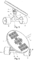
- the illustrated skateboard or roller board essentially comprises running or standing boards 1 and 2, which have a substantially circular or elliptical standing surface.
- the major semi-axis of the ellipse extends in the transverse direction.
- the two standing boards 1, 2 are connected to one another by a connecting rod 3, preferably rotatably mounted below the standing boards 1, 2, the length of which can be individually adjusted, for example depending on the weight and size of the user.
- the standing boards 1, 2 are each attached to a holder 4 and 5, respectively, which forms a bearing block and in which the ends of the connecting rod 3 are also mounted.
- a vertical axis or vertical axis 6 ( Fig. 7 ) stored.
- the standing boards 1, 2, together with the brackets 4, are rotatably or tiltable relative to the longitudinal axis of the skateboard, which is formed by a pin 7 below the standing boards 1, 2.
- the axis 6 is located in the middle under the two standing boards 1, 2.
- the tilting or swiveling movement of the standing boards 1, 2 and the bracket 4 is coupled with a rotation about the vertical axis 6 by means of a gear.
- the maximum rotatability about the vertical axis 6 is predetermined by an angle of, for example, 45 ° with respect to the longitudinal direction of the skateboard.
- the cylindrical pin 7 is mounted in a slide bearing 8 in the holder 4.
- the connecting rod 3 is also mounted in the holder 4 via a slide bearing 9.
- the connecting rod 3 is securely connected to the holder 4 via a knurled screw 9, which protrudes into a bead 10 made in the connecting rod 3.
- a pair of 12 intermeshing bevel gears is attached, which preferably have helical teeth that allow the standing surface of the standing board 1 to be pivoted together with the bracket 4 with respect to the vertical axis 6, for example at an angle of up to 30 °.
- a translation can also be provided between the ring gear and the pinion of the bevel gear 12. If the quotient of the speed of the ring gear is greater than that of the pinion, its speed is lower than that of the ring gear, but the transmitted torque is increased. The reverse case can also be provided.
- the vertically extending hub 11 is connected to a horizontal wheel axle 13 and reinforcement brackets 14 to form a support frame 15.
- Two running wheels 16, 17 are rotatably mounted about the wheel axle 13 in the support frame 15.
- the axle 6 is mounted in the hub 11 at the level of the wheel hub 13 via a ball bearing 18. Below the bevel gears 12, the axle 6 is mounted in the hub 11 via a roller or ball bearing 13; A roller bearing or ball bearing 19 serves to absorb the weight of the user of the skateboard.
- slide bearings 20, 21 are provided for mounting the axle 6 in the hub 11.
- the storage of the wheels 16, 17 opposite the standing board 1 makes it possible to drive the skateboard in tight curves and at the same time to tilt it according to the centrifugal force, which enables the skateboard to move very quickly compared to a non-pivoting skateboard. Additional dynamics are ensured by the fact that, due to the rotatable mounting of the connecting rod 3, the two standing boards 1 and 2 can be pivoted individually.
- the bearings 13, 18, 19, 20, 21 together with the helical bevel gears 12 form the steering gear of the skateboard.
- the standing boards 1, 2 each consist of a sequence of several layers 22, 23, 24, for example made of a plastic.
- the layers 22, 23, 24 are jointly connected to the holder 4 via rivet connections or screws 25 and can be individually replaced.
- the layers 22 to 24 can also be glued together.
- Adhesive knobs 25 protrude from the upper layer 22 and ensure good stability for the user on the standing boards 1, 2. Because of the risk of injury, the adhesive knobs 25 are preferably either made of plastic or metal; however, they can also consist of a different material.
- the holder 4 can be closed and encapsulated by means of a screw 26 for the contamination-free storage of the pin 7 and the axle 6. This measure also serves the stability of the skateboard.
- FIG. 8 9 In another embodiment of the skateboard there is only a single standing board 27 ( Figures 8, 9 ) for use.
- the end of the standing board 27 has approximately the contours of the standing boards 1, 2 and in the middle a connecting area 28 which, for example, has a smaller width than the end areas 29, 30.
- the structure is according to the embodiment Figures 8, 9 identical to that according to the Figures 1 to 7 .
- the connecting rod 3 cannot be rotated in this case. It supports the stability of the skateboard, but can also be omitted, as in Fig. 9 shown.
- the standing board 27 can preferably be exchanged for the standing boards 1, 2.
- skateboard it is equipped with a total of eight wheels.
- Four running wheels 31, 32 support the standing board 1 and four running wheels 31, 32 support the standing board 2 (not shown).
- a pair of running wheels 31, 32 are each rotatably mounted in a lateral support frame 33 and connected via this to the wheel axle 13, which in turn, like the wheel axle 13 according to the FIGS Figs. 1 to 9 illustrated embodiments is arranged rotatably about the vertical axis 6 around together with the support frame 15.
- the support frame 33 is mounted in the support frame 15 around ball, cylinder, roller bearings 19 or other bearings 34. How based on the first embodiment ( Figs. 1 to 7 ) explained, when the standing boards 1 or 2 are tilted relative to the horizontal, each of the support frames 15 performs a rotary movement about the respective vertical axis 6.
- the skateboard has a fourth, in Figs. 13-15 shown embodiment as well as in the third embodiment ( Figures 10 to 12 ) a total of eight running wheels, of which two pairs of running wheels 31, 32 support each of the two standing surfaces 1, 2, of which in Figs. 13-15 only the standing area formed by the standing board 1 is shown.
- a pair of running wheels 31, 32 are each rotatably mounted in a lateral support frame 35.
- the running wheels 31, 32 are connected to the wheel axle 13 and to the supporting frame 15 via the support frame.
- the wheel axle 13 is as in the in Figs. 1 to 12
- the illustrated embodiments are arranged rotatably around the vertical axis 6 together with the support frame 15.
- connection between the support frame 35 and the wheel axle 13 is rigid because a fixed connection is provided between the support frame 35 and the wheel axle 13, for example a screw connection 36. Even if this increases the mobility of the skateboard with respect to the in Figs. 1 to 12 is reduced, the skateboard in this embodiment also performs a rotary movement about the respective vertical axis 6 when the standing surface 1 or 2 is tilted relative to the horizontal of each of the support frames 15. As a result, the two pairs of running wheels 31, 32 are also rotated.
Landscapes
- Motorcycle And Bicycle Frame (AREA)
Applications Claiming Priority (1)
| Application Number | Priority Date | Filing Date | Title |
|---|---|---|---|
| DE102019001363.8A DE102019001363A1 (de) | 2019-02-26 | 2019-02-26 | Skateboard mlt Lenkgetriebe |
Publications (1)
| Publication Number | Publication Date |
|---|---|
| EP3702006A1 true EP3702006A1 (fr) | 2020-09-02 |
Family
ID=69742628
Family Applications (1)
| Application Number | Title | Priority Date | Filing Date |
|---|---|---|---|
| EP20000084.2A Withdrawn EP3702006A1 (fr) | 2019-02-26 | 2020-02-26 | Skateboard pourvu de mécanisme de direction |
Country Status (3)
| Country | Link |
|---|---|
| US (1) | US20200269125A1 (fr) |
| EP (1) | EP3702006A1 (fr) |
| DE (1) | DE102019001363A1 (fr) |
Citations (7)
| Publication number | Priority date | Publication date | Assignee | Title |
|---|---|---|---|---|
| US208508A (en) * | 1878-10-01 | Improvement in roller-skates | ||
| EP0620031B1 (fr) | 1992-02-01 | 1996-11-06 | Karl Kroher | Planche à roulettes |
| FR2810894A1 (fr) * | 2000-07-03 | 2002-01-04 | Olivier Fremy | Dispositif pour planche a roulettes |
| US20060151965A1 (en) * | 2005-01-10 | 2006-07-13 | Jacobus Calitz | Steerable tri-ski downhill rider |
| US20110089659A1 (en) * | 2009-10-15 | 2011-04-21 | Utah State University | Weight Displacement Steering Mechanism |
| US8720916B2 (en) * | 2012-01-06 | 2014-05-13 | Reincarnate, Inc. | Skateboard truck |
| US20140374962A1 (en) * | 2009-08-24 | 2014-12-25 | Robert Gangemi | Method for Manufacturing Professional Grade Skateboard Decks Using Recycled Wood Fiber Veneer Substrate |
Family Cites Families (7)
| Publication number | Priority date | Publication date | Assignee | Title |
|---|---|---|---|---|
| US4955626A (en) * | 1988-01-28 | 1990-09-11 | Smith Eric O M | Skateboards |
| DE29518632U1 (de) * | 1995-11-24 | 1996-01-18 | Lin Liao, Yu-Ying, Feng Yuan | Skateboard |
| AUPQ993700A0 (en) * | 2000-09-06 | 2000-09-28 | Quinto Australia Pty Ltd | Improved truck for skateboard |
| GB2440894A (en) * | 2005-05-10 | 2008-02-13 | Seung Youl Lee | Skateboard capable of all-direction running |
| US20090166993A1 (en) * | 2007-12-30 | 2009-07-02 | Flexibility Concepts, Ltd. | Momentum steering system for a vehicle or carriers |
| DE202011052011U1 (de) * | 2011-11-17 | 2011-12-28 | Crosshouse 24 Ltd. & Co. Kg | Waveboard-Roller |
| DE102016015286A1 (de) * | 2016-12-21 | 2018-06-21 | Franz Schitzhofer | Modulares sportboard |
-
2019
- 2019-02-26 DE DE102019001363.8A patent/DE102019001363A1/de not_active Withdrawn
-
2020
- 2020-02-26 EP EP20000084.2A patent/EP3702006A1/fr not_active Withdrawn
- 2020-02-26 US US16/801,687 patent/US20200269125A1/en not_active Abandoned
Patent Citations (7)
| Publication number | Priority date | Publication date | Assignee | Title |
|---|---|---|---|---|
| US208508A (en) * | 1878-10-01 | Improvement in roller-skates | ||
| EP0620031B1 (fr) | 1992-02-01 | 1996-11-06 | Karl Kroher | Planche à roulettes |
| FR2810894A1 (fr) * | 2000-07-03 | 2002-01-04 | Olivier Fremy | Dispositif pour planche a roulettes |
| US20060151965A1 (en) * | 2005-01-10 | 2006-07-13 | Jacobus Calitz | Steerable tri-ski downhill rider |
| US20140374962A1 (en) * | 2009-08-24 | 2014-12-25 | Robert Gangemi | Method for Manufacturing Professional Grade Skateboard Decks Using Recycled Wood Fiber Veneer Substrate |
| US20110089659A1 (en) * | 2009-10-15 | 2011-04-21 | Utah State University | Weight Displacement Steering Mechanism |
| US8720916B2 (en) * | 2012-01-06 | 2014-05-13 | Reincarnate, Inc. | Skateboard truck |
Also Published As
| Publication number | Publication date |
|---|---|
| DE102019001363A1 (de) | 2020-08-27 |
| US20200269125A1 (en) | 2020-08-27 |
Similar Documents
| Publication | Publication Date | Title |
|---|---|---|
| DE2321669C3 (de) | Rollschuh | |
| DE2707364C3 (de) | Wintersportgerät mit zwei parallelen Gleitkufen | |
| WO2000003773A1 (fr) | Planche a roulettes | |
| EP3500514B1 (fr) | Engin pourvu d'un système de levage latéral | |
| EP1849447B1 (fr) | Fauteuil roulant | |
| EP3448535B1 (fr) | Bloc-essieu de planche à roulettes et planche à roulettes | |
| DE202018105819U1 (de) | Rollbrett | |
| DE4202859C2 (de) | Rollbrett | |
| EP0678443B1 (fr) | Train de roulement, notamment pour machines de travail mobiles et véhicules | |
| DE4311687A1 (de) | Radaufhängung für Fahrgestelle, insbesondere ein einspuriges Rollbrett | |
| DE3338387C2 (fr) | ||
| DE1238788B (de) | Progressive Lenkung fuer Kraftfahrzeuge | |
| DE102019001363A1 (de) | Skateboard mlt Lenkgetriebe | |
| DE102004063563B4 (de) | Kamerawagen mit Lenkgetriebe | |
| DE69207890T2 (de) | Fabrikationsverfahren eines Rollbretts mit körperlichen Antrieb | |
| DE660919C (de) | Gleiskettenfahrzeug mit einstellbaren Laufraedern | |
| DE2447197A1 (de) | Gelenkiges transportband fuer betonfahrzeuge | |
| DE1430301C (de) | Lenkdifferential für einen unbegrenzten Einschlag eines Teiles oder aller Räder von selbstfahrenden oder geschleppten Fahrzeugen | |
| DE733289C (de) | Gleiskettenfahrzeug | |
| DE3633001C2 (fr) | ||
| EP3170379B1 (fr) | Engin agricole comprenant un entrainement de chaine | |
| DE1807136C (de) | Landwirtschaftliche Maschine | |
| DE1555454B1 (de) | Lenkdifferential fuer einen unbegrenzten Einschlag der Raeder in Fahrzeugen | |
| AT76436B (de) | Flugzeug. | |
| DE10114626C2 (de) | Dreidimensionaler Körper |
Legal Events
| Date | Code | Title | Description |
|---|---|---|---|
| PUAI | Public reference made under article 153(3) epc to a published international application that has entered the european phase |
Free format text: ORIGINAL CODE: 0009012 |
|
| STAA | Information on the status of an ep patent application or granted ep patent |
Free format text: STATUS: THE APPLICATION HAS BEEN PUBLISHED |
|
| AK | Designated contracting states |
Kind code of ref document: A1 Designated state(s): AL AT BE BG CH CY CZ DE DK EE ES FI FR GB GR HR HU IE IS IT LI LT LU LV MC MK MT NL NO PL PT RO RS SE SI SK SM TR |
|
| AX | Request for extension of the european patent |
Extension state: BA ME |
|
| STAA | Information on the status of an ep patent application or granted ep patent |
Free format text: STATUS: THE APPLICATION IS DEEMED TO BE WITHDRAWN |
|
| 18D | Application deemed to be withdrawn |
Effective date: 20210303 |