EP3702009A1 - Wasser vergnügungsattraktion - Google Patents
Wasser vergnügungsattraktion Download PDFInfo
- Publication number
- EP3702009A1 EP3702009A1 EP19159753.3A EP19159753A EP3702009A1 EP 3702009 A1 EP3702009 A1 EP 3702009A1 EP 19159753 A EP19159753 A EP 19159753A EP 3702009 A1 EP3702009 A1 EP 3702009A1
- Authority
- EP
- European Patent Office
- Prior art keywords
- sliding
- sliding section
- section
- sliding element
- amusement attraction
- Prior art date
- Legal status (The legal status is an assumption and is not a legal conclusion. Google has not performed a legal analysis and makes no representation as to the accuracy of the status listed.)
- Withdrawn
Links
- XLYOFNOQVPJJNP-UHFFFAOYSA-N water Substances O XLYOFNOQVPJJNP-UHFFFAOYSA-N 0.000 title claims description 29
- 238000001514 detection method Methods 0.000 claims description 6
- 230000002093 peripheral effect Effects 0.000 claims 1
- 230000004048 modification Effects 0.000 description 5
- 238000012986 modification Methods 0.000 description 5
- 230000007423 decrease Effects 0.000 description 3
- 230000001133 acceleration Effects 0.000 description 1
- 230000001419 dependent effect Effects 0.000 description 1
- 230000001960 triggered effect Effects 0.000 description 1
- 238000011144 upstream manufacturing Methods 0.000 description 1
Images




Classifications
-
- A—HUMAN NECESSITIES
- A63—SPORTS; GAMES; AMUSEMENTS
- A63G—MERRY-GO-ROUNDS; SWINGS; ROCKING-HORSES; CHUTES; SWITCHBACKS; SIMILAR DEVICES FOR PUBLIC AMUSEMENT
- A63G21/00—Chutes; Helter-skelters
- A63G21/18—Water-chutes
-
- A—HUMAN NECESSITIES
- A63—SPORTS; GAMES; AMUSEMENTS
- A63G—MERRY-GO-ROUNDS; SWINGS; ROCKING-HORSES; CHUTES; SWITCHBACKS; SIMILAR DEVICES FOR PUBLIC AMUSEMENT
- A63G3/00—Water roundabouts, e.g. freely floating
Definitions
- the present invention relates to an amusement and leisure slide for attraction parks, hotels, business or shopping centers with various combinations of thrilling experiences.
- a bowl structure is used as an element of the water slide embodiment.
- Such bowl-type slides are generally embodied such that the users enter into the bowl by means of a tangent orbital movement by using a tube before the users exit through a hole provided under the bowl and the users slide in various spiral or elliptic shapes inside the bowl, and the users finish sliding in a water pool or in a safe area.
- the design of the outlet region providing exit of the user from the bowl differs. In case the user, who slides in a high speed manner, does not fall into a water pool, an outlet opening design which will slow down the speed of the user is needed.
- a waterslide bowl element which has a bottom wall configured to form a throat around a rider exit opening in the bottom of the bowl.
- the bowl holds an annular ring of water around the throat that slows down and conducts the rider to the exit opening and a flume in which the waterslide ride continues.
- the depth of said annular ring is equal at each point of the annular form.
- the design relates to a bowl-type water slide for the purpose of entertainment and having a configuration where the user, who enters into the inlet region at a predetermined speed, may exit the bowl-type water slide in a safe manner through a narrow outlet opening provided in the outlet region at the periphery of the bowl.
- the movement of the user is achieved through an initial speed gathered before entering into the bowl. Once the user is inside the bowl, he stays inside as long as the momentum acquired by the initial acceleration is sufficient.
- an amusement attraction comprising a sliding section mounted on actuators allowing it to modify , move, translate or tilt the sliding section, the amusement attraction further comprises a detection means of the position of at least one sliding element within the sliding section, and control means to control the movement of the sliding section so that the sliding element slides from a starting position toward an end position according to a plurality of paths.
- the key solution of the present invention is to transfer energy to the user or the sliding element by moving and/or tilting the sliding section in accordance with the position of the sliding element.
- control means should know movement characteristics (such as the position, speed) of the sliding element so that the moving and/or tilting of the sliding section is concurrent with the movement of the sliding element.
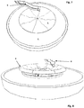
- the figure 1 is an overall view of the invention.
- the sliding section 1 having the shape of a bowl, is mounted on a frame comprising actuators 3.
- the sliding section 1 can be moved or tilted or a combination of both.
- movement we understand a horizontal movement in X and Y, the attitude of the sliding section being unchanged.
- tilting we understand a change of the attitude of the sliding section, the X/Y position (horizontal) being unchanged.
- the two modifications of the sliding section can be combined to move and tilt at the same time.
- the expression modify or modification of the sliding section means moving, tilting or a combination of moving and tilting. To achieve the various tilting orientations of the sliding section, at least two actuators 3 are required.
- the sliding section 1 is rigid and extending one actuator in a six actuator's embodiment, has the consequence of inclining the sliding section and thus changing the attitude of the sliding section 1. If the second actuator is also extended, the inclination of the attitude of the sliding section is changed.
- a Stewart platform is represented as a configuration of the 6 actuators, which has the advantage of the symmetry and simplicity. Other serial embodiments of actuators can also be designed.
- the sliding section 1 comprises a central opening 2 to allow the sliding element to exit the sliding section.
- the figure 2 illustrates a cross-section of the figure 1 showing the actuators 2 allowing to move and/or tilt the sliding section 1.
- the sliding section 1 comprises the central opening 2 to let the sliding element leave the sliding section.
- the figure 3 illustrates a version with an entry slide 6 located on top of the sliding section 1.
- the sliding element joins the sliding section through the entry slide 6. Once the sliding element has terminated its journey, the sliding section is modified so that the sliding element exits by the periphery of the sliding section.
- the figure 4 differs from the figure 3 in the way the sliding elements exits the sliding section 1.
- the sliding section is modified so that the sliding element exits through the central opening 2.
- a camera 5 is located on top of the sliding section to acquire the position of the sliding element.
- the figure 5 illustrates an example in which the sliding section 1 is surrounded by a water channel 7.
- the movements of the sliding section are preprogrammed and triggered by the entry of the sliding element into the sliding section.
- the behavior of a standard sliding element is known and the movement of the sliding section can be determined in advance without knowing the position of the sliding element.
- the programmed movements applied to the sliding section are started.
- the entry of the sliding section comprises a scale to determine the weight of the sliding element. With the weight, the control means can calculate the expected behavior of the sliding element and the movement of the sliding section can be optimized to bring a satisfactorily experience to the user.
- control of the modification of the sliding section is directly dependent on the sliding element's position.
- the position of the sliding element can be detected according to various ways.
- the control means comprises a camera 5 preferably mounted above the sliding section and having a field of view covering the sliding section (see figure 6 ). The image of the camera is analyzed to detect the position of the sliding element and the position is used by the control means to determine the modification to be applied to the sliding section.
- the sliding element comprises a beacon which transmits a radio signal.
- the beacon can be held by a user or be mounted on a sliding vehicle. With the assistance of at least two receivers, the position of the beacon is detected within the sliding section.
- the figure 12 illustrates the way the attitude of the sliding section is modified.
- the control means detects the position of the sliding element.
- a sliding element can be one person or a riding vehicle such as a bow or a cart. The user or users are mounted on the riding vehicle to glide within the sliding section.
- the control means controls the actuators in order to create a movement such as a change of attitude or a movement.
- a movement such as a change of attitude or a movement.
- the change of attitude creates a slope so that the sliding element slides within the sliding section.
- the path, illustrated by the arrow is determined by the control means. To understand the way the path is determined, the figure 12 illustrates different positions of the sliding element thus leading to different attitude of the sliding section.
- the movement of the sliding section (the movement is illustrated by the white arrow) follows the sliding element by creating a constant slope.
- the attitude of the sliding section is modified in order to create a decline (or a slope) allowing the sliding element to glide.
- the control means can determine the temporary target position B by adjusting the attitude of the sliding section. Once the sliding element has reached the position B, the attitude of the sliding section is modified to lead the sliding element to the position C.
- the control means can maintain a movement of the sliding element as long as desired. By adjusting the actuators, the sliding element can follow linear and elliptic paths.
- the speed of the sliding element is determined by the control means, in particular with the means to detect the position.
- the speed information can be used to anticipate the location of the sliding element during the movement.
- the attitude could be constantly modified during the movement of the sliding element and the magnitude of the modification of the attitude can also depend on the speed of the sliding element.
- the attitude of the sliding section is controlled by the control means so that in the first part of a path A-B, the sliding element accelerates using the decline of the sliding section. Once the sliding element has reached the half of the journey A-B, the control means changes the attitude of the sliding section to decrease the speed of the sliding element. The speed is controlled in order to avoid that the sliding element is ejected from the sliding section.
- the control means can position the sliding section so that the sliding element avoids following a straight line between the initial position A to the target position C passing through the central part of the sliding section. In this way, the sliding element can move as long as the control means calculate an elliptic path. Once the time to enjoy the sliding experience is over, the control means calculates a path that leads to the center of the sliding section at a controlled speed.
- the central part comprises an outlet in the shape of a tube to allow the sliding element to enter and be evacuated from the sliding section.
- the sliding section can be surrounded by a collecting channel (see figure 5 and 6 , element 7). Since the control means can control the speed and the position of the sliding element, the attitude can be adjusted so that the sliding element terminates its journey at the periphery of the sliding section at low speed, allowing a smooth transfer from the sliding section to the collecting channel.
- the figures 7 and 8 illustrate the collecting channel 7.
- the entry into the sliding section is achieved through an entry slide 6.
- the sliding section 1 has preferably a bowl shape with a surrounding lip 4.
- the sliding element stays into the bowl part of the sliding section and moves according to the change of attitude of the sliding section. Once the time is over, the attitude is changed so that the sliding element passes the lip of the sliding section and therefore exits the sliding section to arrive into the collecting channel 7.
- the figure 9 and 10 is another example of the movement of the sliding section 1.
- the sliding element 9 slides along on the wall of the sliding section thanks to the slope created by the tilting of the sliding section.
- the exit is one opening into the wall of the sliding section.
- the figure 10 illustrates the end of the journey and the attitude of the sliding section is changed so that the sliding element is conveyed to the exit.
- the exit is connected to the connecting channel as illustrated in the figures 7 and 8 .
- the figure 11 shows an example of two sliding elements at the same time in the sliding section.
- the control means can determine a movement of the sliding section so that the two sliding elements could move from a position A to a position B.
- the wall of the sliding section comprises a tube 8 to allow the sliding elements entering into the sliding section.
- the sliding section comprises a plurality of water outlets in order to create a water film on top of all or part of the surface of the sliding section.
- the water outlets are preferably located at the periphery of the sliding section and the water inlets are provided at various portions of the sliding section.
- the control means can also open or close the water inlets and water outlets. In the example of the figure 12 , the water outlets close to the position A are open and the water inlets close to the same position are closed so that the water flows from the position A to the position B. At the position B, the water inlets are open to collect the water.
- the water outlets are opened around this position to create a film towards the position B.
- the water inlets close to the lowest portion of the sliding section are open and the water outlets upstream to that position are open.
- the water outlets are open below the sliding element and in front the sliding element so as to create the film of water allowing the sliding element to glide on top of the film.
- the sliding portion is dry and the sliding element comprises wheels allowing it to roll in all directions.
- the figure 3 illustrates one example of the sliding section. It is not necessary that the sliding section is flat but can also comprises valleys and hills to create a more exciting path for a user.
- the stating position and the exit can be anywhere along the edge of the sliding section.
- a collecting channel is positioned so that the sliding element, while exiting the sliding section, joins the collecting channel.
- the collecting channel is a water channel leading the sliding element to the main exit of the amusement attraction.
Landscapes
- Toys (AREA)
Priority Applications (3)
| Application Number | Priority Date | Filing Date | Title |
|---|---|---|---|
| EP19159753.3A EP3702009A1 (de) | 2019-02-27 | 2019-02-27 | Wasser vergnügungsattraktion |
| PCT/EP2020/055215 WO2020174076A1 (en) | 2019-02-27 | 2020-02-27 | Water amusement attraction |
| US17/897,899 US20230063775A1 (en) | 2019-02-27 | 2022-08-29 | Amusement attraction |
Applications Claiming Priority (1)
| Application Number | Priority Date | Filing Date | Title |
|---|---|---|---|
| EP19159753.3A EP3702009A1 (de) | 2019-02-27 | 2019-02-27 | Wasser vergnügungsattraktion |
Publications (1)
| Publication Number | Publication Date |
|---|---|
| EP3702009A1 true EP3702009A1 (de) | 2020-09-02 |
Family
ID=65628690
Family Applications (1)
| Application Number | Title | Priority Date | Filing Date |
|---|---|---|---|
| EP19159753.3A Withdrawn EP3702009A1 (de) | 2019-02-27 | 2019-02-27 | Wasser vergnügungsattraktion |
Country Status (3)
| Country | Link |
|---|---|
| US (1) | US20230063775A1 (de) |
| EP (1) | EP3702009A1 (de) |
| WO (1) | WO2020174076A1 (de) |
Cited By (1)
| Publication number | Priority date | Publication date | Assignee | Title |
|---|---|---|---|---|
| US20230063775A1 (en) * | 2019-02-27 | 2023-03-02 | Fischer Design-Concepts Sarl | Amusement attraction |
Citations (6)
| Publication number | Priority date | Publication date | Assignee | Title |
|---|---|---|---|---|
| US2806697A (en) * | 1953-01-09 | 1957-09-17 | Huhn Robert | Free carriage roundabout |
| US5433671A (en) * | 1993-12-27 | 1995-07-18 | Davis; Walter D. | Water amusement ride |
| US6485372B2 (en) | 2000-12-13 | 2002-11-26 | Whitewater West Industries Ltd. | Waterslide and waterslide bowl |
| US7780537B2 (en) * | 2007-08-31 | 2010-08-24 | Whitewater West Industries Ltd. | Waterslide run-out bowl |
| US20160136529A1 (en) * | 2012-11-09 | 2016-05-19 | Whitewater West Industries Ltd. | Interactive amusement attraction system and method |
| WO2018080409A1 (en) | 2016-10-25 | 2018-05-03 | Polin Su Parklari Ve Havuz Sistemleri Anonim Sirketi | A bowl-type water slide |
Family Cites Families (32)
| Publication number | Priority date | Publication date | Assignee | Title |
|---|---|---|---|---|
| US4196900A (en) * | 1977-03-03 | 1980-04-08 | Demag Aktiengesellschaft | Slide |
| US4194733A (en) * | 1978-07-05 | 1980-03-25 | Whitehouse Ben Jr | Water slide system |
| US4836521A (en) * | 1988-09-23 | 1989-06-06 | Barber Gerald L | Whirlpool amusement ride |
| US6702687B1 (en) * | 2000-06-23 | 2004-03-09 | Nbgs International, Inc. | Controller system for water amusement devices |
| US7713134B2 (en) * | 2002-06-18 | 2010-05-11 | Proslide Technology Inc. | Reducing radius slide feature |
| US7967692B2 (en) * | 2006-04-24 | 2011-06-28 | Werner Michael F | Water slide audio visual entertainment system |
| US8192291B2 (en) * | 2008-02-28 | 2012-06-05 | Whitewater West Industries Ltd. | Waterslide bowl with troughs |
| GB0818483D0 (en) * | 2008-10-08 | 2008-11-12 | Cuttell David J | Water or leisure slide |
| CA2778601C (en) * | 2009-11-13 | 2019-01-08 | Proslide Technology Inc. | Water slide |
| CN103209742A (zh) * | 2010-11-12 | 2013-07-17 | 斯博拉什塔库勒公司 | 具有移动段的娱乐滑道 |
| US8684855B2 (en) * | 2011-04-08 | 2014-04-01 | Universal City Studios Llc | Articulated waterslide |
| CA2866024C (en) * | 2012-02-29 | 2019-05-07 | Whitewater West Industries Ltd. | Trapdoor drop amusement mechanism |
| PL2830729T3 (pl) * | 2012-03-27 | 2016-11-30 | Zjeżdżalnia rekreacyjno-rozrywkowa | |
| USD697159S1 (en) * | 2012-05-30 | 2014-01-07 | Polin su Parklar ve Havuz Sistemleri Anonim Sirketi | Water park unit |
| DE102013222910A1 (de) * | 2013-11-11 | 2015-05-13 | Mack Rides Gmbh & Co Kg | Vergnügungsbahn mit beweglichem Bahnabschnitt |
| CN111346388B (zh) * | 2014-06-13 | 2023-03-21 | 波乐思来技术股份有限公司 | 滑梯部件 |
| DE102015104124B3 (de) * | 2015-03-19 | 2016-05-12 | Klarer Freizeitanlagen Ag | Wasserrutsche sowie Wasserrutschensystem |
| FR3037819B1 (fr) * | 2015-06-26 | 2019-06-07 | Hydrostadium | Riviere d'eau vive demontable |
| MY191226A (en) * | 2016-07-11 | 2022-06-09 | Polin Su Parklari Ve Havuz Sistemleri Anonim Sirketi | A bowl-type waterslide assembly |
| AU2016415163B2 (en) * | 2016-07-11 | 2019-09-19 | Polin Su Parklari Ve Havuz Sistemleri Anonim Sirketi | A waterslide system |
| USD855136S1 (en) * | 2017-06-08 | 2019-07-30 | Whitewater West Industries Ltd. | Looping ride element |
| US20190143226A1 (en) * | 2017-11-10 | 2019-05-16 | Whitewater West Industries Ltd. | Amusement or water ride attraction including sub-elements |
| CA3045278A1 (en) * | 2018-06-04 | 2019-12-04 | Kelly Sall | Spinning raft ride |
| US11879525B2 (en) * | 2018-10-22 | 2024-01-23 | The Rocky Mountain Surf Company, Llc | Wave machine |
| EP3702009A1 (de) * | 2019-02-27 | 2020-09-02 | Fischer Design-Concepts Sàrl | Wasser vergnügungsattraktion |
| CA3169230A1 (en) * | 2020-02-07 | 2021-08-12 | Proslide Technology Inc. | Multi-lane water slide feature |
| US20230277949A1 (en) * | 2020-06-25 | 2023-09-07 | Proslide Technology Inc. | Water ride with floating section |
| CA3196449A1 (en) * | 2020-10-21 | 2022-04-28 | Shane Jensen | Slide attraction |
| EP4232174B1 (de) * | 2020-10-22 | 2026-08-19 | Whitewater West Industries Ltd | Vergnügungsattraktion mit gekoppelten fahrpfaden |
| DE102021107560A1 (de) * | 2021-03-25 | 2022-09-29 | Aquarena Holding Gmbh | Verfahren zur Steuerung einer Rutschrichtung in einer Weiche sowie Weiche für eine Rutsche, insbesondere Wasserrutsche |
| DE102021107558A1 (de) * | 2021-03-25 | 2022-09-29 | Aquarena Holding Gmbh | Rutsche, insbesondere Wasserrutsche |
| WO2023082026A1 (en) * | 2021-11-15 | 2023-05-19 | Whitewater West Industries Ltd. | Conjoined multiple bowl water slide feature |
-
2019
- 2019-02-27 EP EP19159753.3A patent/EP3702009A1/de not_active Withdrawn
-
2020
- 2020-02-27 WO PCT/EP2020/055215 patent/WO2020174076A1/en not_active Ceased
-
2022
- 2022-08-29 US US17/897,899 patent/US20230063775A1/en not_active Abandoned
Patent Citations (6)
| Publication number | Priority date | Publication date | Assignee | Title |
|---|---|---|---|---|
| US2806697A (en) * | 1953-01-09 | 1957-09-17 | Huhn Robert | Free carriage roundabout |
| US5433671A (en) * | 1993-12-27 | 1995-07-18 | Davis; Walter D. | Water amusement ride |
| US6485372B2 (en) | 2000-12-13 | 2002-11-26 | Whitewater West Industries Ltd. | Waterslide and waterslide bowl |
| US7780537B2 (en) * | 2007-08-31 | 2010-08-24 | Whitewater West Industries Ltd. | Waterslide run-out bowl |
| US20160136529A1 (en) * | 2012-11-09 | 2016-05-19 | Whitewater West Industries Ltd. | Interactive amusement attraction system and method |
| WO2018080409A1 (en) | 2016-10-25 | 2018-05-03 | Polin Su Parklari Ve Havuz Sistemleri Anonim Sirketi | A bowl-type water slide |
Cited By (1)
| Publication number | Priority date | Publication date | Assignee | Title |
|---|---|---|---|---|
| US20230063775A1 (en) * | 2019-02-27 | 2023-03-02 | Fischer Design-Concepts Sarl | Amusement attraction |
Also Published As
| Publication number | Publication date |
|---|---|
| WO2020174076A1 (en) | 2020-09-03 |
| US20230063775A1 (en) | 2023-03-02 |
Similar Documents
| Publication | Publication Date | Title |
|---|---|---|
| CN106470744B (zh) | 水上乘坐设施 | |
| US6485372B2 (en) | Waterslide and waterslide bowl | |
| US8579715B2 (en) | Amusement slide elements and systems | |
| CN109475779B (zh) | 水滑道系统 | |
| US6450891B1 (en) | Slide apparatus | |
| RU2611030C2 (ru) | Игровой спуск | |
| US20230063775A1 (en) | Amusement attraction | |
| EP2624926A2 (de) | Gleitelemente und systeme für amüsement-zwecke | |
| WO2014073952A1 (en) | Slide track with improved capacity comprising a plurality of selectable downstream slide ways | |
| US20140179451A1 (en) | Capacity of slide track | |
| WO1998023348A2 (en) | Closed watercraft for transporting people in amusement parks, and associated travel path | |
| KR102653855B1 (ko) | 공기 부상식 개인 이동 장치 | |
| CN112930220B (zh) | 滑水道结构 | |
| WO2021251916A1 (en) | A waterslide structure | |
| JP2577242B2 (ja) | シーソー機構を設けた水上滑り台 | |
| TR2022020078T2 (tr) | Bi̇r zip line’a sahi̇p bi̇r su kaydiraği | |
| TR2022018949T2 (tr) | Bi̇r su kaydiraği yapisi |
Legal Events
| Date | Code | Title | Description |
|---|---|---|---|
| PUAI | Public reference made under article 153(3) epc to a published international application that has entered the european phase |
Free format text: ORIGINAL CODE: 0009012 |
|
| STAA | Information on the status of an ep patent application or granted ep patent |
Free format text: STATUS: THE APPLICATION HAS BEEN PUBLISHED |
|
| AK | Designated contracting states |
Kind code of ref document: A1 Designated state(s): AL AT BE BG CH CY CZ DE DK EE ES FI FR GB GR HR HU IE IS IT LI LT LU LV MC MK MT NL NO PL PT RO RS SE SI SK SM TR |
|
| AX | Request for extension of the european patent |
Extension state: BA ME |
|
| STAA | Information on the status of an ep patent application or granted ep patent |
Free format text: STATUS: THE APPLICATION IS DEEMED TO BE WITHDRAWN |
|
| 18D | Application deemed to be withdrawn |
Effective date: 20210303 |