EP3702132A1 - Procédé de fabrication générative par lithographie de composants tridimensionnels - Google Patents
Procédé de fabrication générative par lithographie de composants tridimensionnels Download PDFInfo
- Publication number
- EP3702132A1 EP3702132A1 EP19450004.7A EP19450004A EP3702132A1 EP 3702132 A1 EP3702132 A1 EP 3702132A1 EP 19450004 A EP19450004 A EP 19450004A EP 3702132 A1 EP3702132 A1 EP 3702132A1
- Authority
- EP
- European Patent Office
- Prior art keywords
- component
- partial structures
- another
- substructures
- irradiation device
- Prior art date
- Legal status (The legal status is an assumption and is not a legal conclusion. Google has not performed a legal analysis and makes no representation as to the accuracy of the status listed.)
- Granted
Links
Images
Classifications
-
- B—PERFORMING OPERATIONS; TRANSPORTING
- B29—WORKING OF PLASTICS; WORKING OF SUBSTANCES IN A PLASTIC STATE IN GENERAL
- B29C—SHAPING OR JOINING OF PLASTICS; SHAPING OF MATERIAL IN A PLASTIC STATE, NOT OTHERWISE PROVIDED FOR; AFTER-TREATMENT OF THE SHAPED PRODUCTS, e.g. REPAIRING
- B29C64/00—Additive manufacturing, i.e. manufacturing of three-dimensional [3D] objects by additive deposition, additive agglomeration or additive layering, e.g. by 3D printing, stereolithography or selective laser sintering
- B29C64/10—Processes of additive manufacturing
- B29C64/106—Processes of additive manufacturing using only liquids or viscous materials, e.g. depositing a continuous bead of viscous material
- B29C64/124—Processes of additive manufacturing using only liquids or viscous materials, e.g. depositing a continuous bead of viscous material using layers of liquid which are selectively solidified
-
- B—PERFORMING OPERATIONS; TRANSPORTING
- B29—WORKING OF PLASTICS; WORKING OF SUBSTANCES IN A PLASTIC STATE IN GENERAL
- B29C—SHAPING OR JOINING OF PLASTICS; SHAPING OF MATERIAL IN A PLASTIC STATE, NOT OTHERWISE PROVIDED FOR; AFTER-TREATMENT OF THE SHAPED PRODUCTS, e.g. REPAIRING
- B29C64/00—Additive manufacturing, i.e. manufacturing of three-dimensional [3D] objects by additive deposition, additive agglomeration or additive layering, e.g. by 3D printing, stereolithography or selective laser sintering
- B29C64/10—Processes of additive manufacturing
- B29C64/106—Processes of additive manufacturing using only liquids or viscous materials, e.g. depositing a continuous bead of viscous material
- B29C64/124—Processes of additive manufacturing using only liquids or viscous materials, e.g. depositing a continuous bead of viscous material using layers of liquid which are selectively solidified
- B29C64/129—Processes of additive manufacturing using only liquids or viscous materials, e.g. depositing a continuous bead of viscous material using layers of liquid which are selectively solidified characterised by the energy source therefor, e.g. by global irradiation combined with a mask
- B29C64/135—Processes of additive manufacturing using only liquids or viscous materials, e.g. depositing a continuous bead of viscous material using layers of liquid which are selectively solidified characterised by the energy source therefor, e.g. by global irradiation combined with a mask the energy source being concentrated, e.g. scanning lasers or focused light sources
-
- B—PERFORMING OPERATIONS; TRANSPORTING
- B29—WORKING OF PLASTICS; WORKING OF SUBSTANCES IN A PLASTIC STATE IN GENERAL
- B29C—SHAPING OR JOINING OF PLASTICS; SHAPING OF MATERIAL IN A PLASTIC STATE, NOT OTHERWISE PROVIDED FOR; AFTER-TREATMENT OF THE SHAPED PRODUCTS, e.g. REPAIRING
- B29C64/00—Additive manufacturing, i.e. manufacturing of three-dimensional [3D] objects by additive deposition, additive agglomeration or additive layering, e.g. by 3D printing, stereolithography or selective laser sintering
- B29C64/20—Apparatus for additive manufacturing; Details thereof or accessories therefor
- B29C64/227—Driving means
- B29C64/236—Driving means for motion in a direction within the plane of a layer
-
- B—PERFORMING OPERATIONS; TRANSPORTING
- B29—WORKING OF PLASTICS; WORKING OF SUBSTANCES IN A PLASTIC STATE IN GENERAL
- B29C—SHAPING OR JOINING OF PLASTICS; SHAPING OF MATERIAL IN A PLASTIC STATE, NOT OTHERWISE PROVIDED FOR; AFTER-TREATMENT OF THE SHAPED PRODUCTS, e.g. REPAIRING
- B29C64/00—Additive manufacturing, i.e. manufacturing of three-dimensional [3D] objects by additive deposition, additive agglomeration or additive layering, e.g. by 3D printing, stereolithography or selective laser sintering
- B29C64/20—Apparatus for additive manufacturing; Details thereof or accessories therefor
- B29C64/245—Platforms or substrates
-
- B—PERFORMING OPERATIONS; TRANSPORTING
- B29—WORKING OF PLASTICS; WORKING OF SUBSTANCES IN A PLASTIC STATE IN GENERAL
- B29C—SHAPING OR JOINING OF PLASTICS; SHAPING OF MATERIAL IN A PLASTIC STATE, NOT OTHERWISE PROVIDED FOR; AFTER-TREATMENT OF THE SHAPED PRODUCTS, e.g. REPAIRING
- B29C64/00—Additive manufacturing, i.e. manufacturing of three-dimensional [3D] objects by additive deposition, additive agglomeration or additive layering, e.g. by 3D printing, stereolithography or selective laser sintering
- B29C64/20—Apparatus for additive manufacturing; Details thereof or accessories therefor
- B29C64/255—Enclosures for the building material, e.g. powder containers
-
- B—PERFORMING OPERATIONS; TRANSPORTING
- B29—WORKING OF PLASTICS; WORKING OF SUBSTANCES IN A PLASTIC STATE IN GENERAL
- B29C—SHAPING OR JOINING OF PLASTICS; SHAPING OF MATERIAL IN A PLASTIC STATE, NOT OTHERWISE PROVIDED FOR; AFTER-TREATMENT OF THE SHAPED PRODUCTS, e.g. REPAIRING
- B29C64/00—Additive manufacturing, i.e. manufacturing of three-dimensional [3D] objects by additive deposition, additive agglomeration or additive layering, e.g. by 3D printing, stereolithography or selective laser sintering
- B29C64/20—Apparatus for additive manufacturing; Details thereof or accessories therefor
- B29C64/264—Arrangements for irradiation
- B29C64/268—Arrangements for irradiation using laser beams; using electron beams [EB]
-
- B—PERFORMING OPERATIONS; TRANSPORTING
- B29—WORKING OF PLASTICS; WORKING OF SUBSTANCES IN A PLASTIC STATE IN GENERAL
- B29C—SHAPING OR JOINING OF PLASTICS; SHAPING OF MATERIAL IN A PLASTIC STATE, NOT OTHERWISE PROVIDED FOR; AFTER-TREATMENT OF THE SHAPED PRODUCTS, e.g. REPAIRING
- B29C64/00—Additive manufacturing, i.e. manufacturing of three-dimensional [3D] objects by additive deposition, additive agglomeration or additive layering, e.g. by 3D printing, stereolithography or selective laser sintering
- B29C64/20—Apparatus for additive manufacturing; Details thereof or accessories therefor
- B29C64/264—Arrangements for irradiation
- B29C64/286—Optical filters, e.g. masks
-
- B—PERFORMING OPERATIONS; TRANSPORTING
- B33—ADDITIVE MANUFACTURING TECHNOLOGY
- B33Y—ADDITIVE MANUFACTURING, i.e. MANUFACTURING OF THREE-DIMENSIONAL [3D] OBJECTS BY ADDITIVE DEPOSITION, ADDITIVE AGGLOMERATION OR ADDITIVE LAYERING, e.g. BY 3D PRINTING, STEREOLITHOGRAPHY OR SELECTIVE LASER SINTERING
- B33Y10/00—Processes of additive manufacturing
-
- B—PERFORMING OPERATIONS; TRANSPORTING
- B33—ADDITIVE MANUFACTURING TECHNOLOGY
- B33Y—ADDITIVE MANUFACTURING, i.e. MANUFACTURING OF THREE-DIMENSIONAL [3D] OBJECTS BY ADDITIVE DEPOSITION, ADDITIVE AGGLOMERATION OR ADDITIVE LAYERING, e.g. BY 3D PRINTING, STEREOLITHOGRAPHY OR SELECTIVE LASER SINTERING
- B33Y30/00—Apparatus for additive manufacturing; Details thereof or accessories therefor
-
- G—PHYSICS
- G03—PHOTOGRAPHY; CINEMATOGRAPHY; ANALOGOUS TECHNIQUES USING WAVES OTHER THAN OPTICAL WAVES; ELECTROGRAPHY; HOLOGRAPHY
- G03F—PHOTOMECHANICAL PRODUCTION OF TEXTURED OR PATTERNED SURFACES, e.g. FOR PRINTING, FOR PROCESSING OF SEMICONDUCTOR DEVICES; MATERIALS THEREFOR; ORIGINALS THEREFOR; APPARATUS SPECIALLY ADAPTED THEREFOR
- G03F7/00—Photomechanical, e.g. photolithographic, production of textured or patterned surfaces, e.g. printing surfaces; Materials therefor, e.g. comprising photoresists; Apparatus specially adapted therefor
- G03F7/0002—Lithographic processes using patterning methods other than those involving the exposure to radiation, e.g. by stamping
-
- B—PERFORMING OPERATIONS; TRANSPORTING
- B29—WORKING OF PLASTICS; WORKING OF SUBSTANCES IN A PLASTIC STATE IN GENERAL
- B29K—INDEXING SCHEME ASSOCIATED WITH SUBCLASSES B29B, B29C OR B29D, RELATING TO MOULDING MATERIALS OR TO MATERIALS FOR MOULDS, REINFORCEMENTS, FILLERS OR PREFORMED PARTS, e.g. INSERTS
- B29K2995/00—Properties of moulding materials, reinforcements, fillers, preformed parts or moulds
- B29K2995/0037—Other properties
- B29K2995/0094—Geometrical properties
- B29K2995/0097—Thickness
Definitions
- the invention relates to a method for the lithography-based generative production of a three-dimensional component, in which electromagnetic radiation emitted by an irradiation device is successively focused on focal points within a material, whereby a volume element of the material located at the focal point is solidified by means of multiphoton absorption, with a writing area of the irradiation device a partial structure is built up from the volume elements and a plurality of partial structures are arranged next to one another.
- a method for forming a shaped body in which the solidification of a liquid photosensitive material is carried out by means of multiphoton absorption is, for example, from DE 10111422 A1 known.
- a focused laser beam is radiated into the bath of the photosensitive material, whereby the irradiation conditions for a multiphoton absorption process that triggers the solidification are only met in the immediate vicinity of the focus, so that the focus of the beam is adjusted within the bath volume according to the geometric data of the molded body to be produced leads to the areas to be consolidated.
- the material bath is irradiated in the method according to FIG DE 10111422 A1 from above, the radiation intensity being selected so that the liquid is essentially transparent for the radiation used above the focal point, so that a direct polymerisation of the bath material takes place selectively within the bath volume, ie also far below the bath surface.
- Irradiation devices for multiphoton absorption methods include optics for focusing a laser beam and a deflection device for deflecting the laser beam. Due to the design, such irradiation devices have a limited writing area within which the deflection device moves the laser beam. The specified writing area is usually smaller than the volume required for the component to be manufactured. The component must therefore be divided into a plurality of substructures which each correspond to a writing area and are built up one after the other. After the construction of a partial structure, the irradiation device for the construction of the next partial structure is displaced relative to the material and the next partial area is written directly to the preceding partial area. This so-called “stitching" can cause a discontinuity in the joint area between two adjacent substructures, which forms a mechanical weak point in the component.
- the present invention aims to provide an improved method with which not only the problem of shading is taken into account, but also the mechanical susceptibility of the component to breakage caused by the stitching method is improved.
- the invention provides in a method of the type mentioned at the outset that partial structures are arranged one above the other, so that upper partial structures bridge the interface (s) between lower partial structures arranged next to one another. Because the component is broken down not only into partial structures lying next to one another, but also into superimposed partial structures, the thickness of the partial structures can be selected to be smaller. In particular, the thickness of the substructures can be selected to be so small that no shadows arise.
- the component comprises a plurality of layers lying one on top of the other, each of which is formed from a plurality of substructures arranged next to one another, the component is built up in layers, with the substructures of an upper layer bridging the interface (s) between adjacent substructures of the layer immediately below.
- the component is built up in layers, with the substructures of an upper layer bridging the interface (s) between adjacent substructures of the layer immediately below.
- several substructures can first be built up next to one another before the substructures of the next, upper layer are built up immediately above.
- shadows are significantly reduced or, if the layers are made correspondingly thin, completely avoided because the shadow is only generated by the height of a layer.
- the invention thus takes a different approach than that EP 3093123 A1 , where the component is only built up from partial structures arranged next to one another, ie from a single layer.
- the method according to the invention is thus different from the solution according to FIG EP 3093123 A1
- the depth of the substructures is limited to the thickness of a layer, which in turn is selected to be no greater than the depth of penetration without shading.
- the interfaces preferably run parallel to the direction of entry.
- the layer-by-layer structure of the component also makes it possible to improve the mechanical stability in that the partial structures of a layer bridge the interface (s) between adjacent partial structures of the layer immediately below. This creates an offset between the substructures of the individual layer, similar to the offset of bricks in a masonry bond. Due to the offset, the weak points occurring due to the joints or interfaces between two adjacent substructures of a layer are compensated and, in particular, the spread of cracks along the interfaces in the component is prevented.
- a partial structure is understood to mean an area of the body to be produced which corresponds to the writing area of the irradiation device and whose thickness, measured in the direction of the entry direction, corresponds to the thickness of one layer in the case of a layered structure.
- the writing area of the irradiation device is displaced transversely to the entry direction of the irradiation device by changing the relative position of the irradiation device relative to the material, in order to build up a next substructure after building a partial structure.
- either the irradiation device can be displaced relative to the stationary material or the material or the container holding the material can be displaced relative to the stationary irradiation device.
- the interface between layers lying one on top of the other is continuously flat.
- the adjacent substructures forming a layer thus have the same thickness, so that a layer of uniform thickness results.
- the layers here extend transversely to the direction of entry.
- the interface between substructures lying one on top of the other can also be designed in a stepped manner.
- an upper substructure has a surface on its underside which has a step at the interface between two lower substructures.
- a lower substructure has a surface on its upper side which has a step at the interface between two upper substructures. Due to such a step configuration, the thickness of an adjacent partial structure appears to be lower by the height of the step, so that the shading effect can be further reduced or the thickness of the partial structures can be increased by the height of the step without worsening the shading conditions.
- an advantageous embodiment provides that the height of the step 10-50%, in particular 20-40%, of the thickness (measured in the height direction) of the substructure is selected.
- the offset of the substructures lying on top of one another is preferably designed in such a way that the substructures are adequately covered or overlapped.
- a preferred embodiment provides that two lower substructures adjoining one another at an interface are each overlapped by the upper substructure bridging this interface by at least 10%, preferably at least 30%, particularly preferably at least 40%, in particular 50%.
- the thickness of the substructures and / or the layers is less than 100 ⁇ m, preferably less than 50 ⁇ m, preferably less than 30 ⁇ m, in particular less than 10 ⁇ m ⁇ m.
- the thickness of the substructures and / or the layers is at most 10 ⁇ m with a numerical aperture of the irradiation system of 1.4, at most 30 ⁇ m with a numerical aperture of the irradiation system of 0.8 and with a numerical aperture of the irradiation system of 0.4 at most 50 ⁇ m.
- the individual substructures can be built up in layers, that is, made up of several layers.
- a particularly preferred procedure results when the material is on a material carrier, e.g. in a trough, and the material is irradiated from below through the material carrier which is at least partially permeable to the radiation.
- a building platform can be positioned at a distance from the material carrier and the component can be built up on the building platform by solidifying material located between the building platform and the material carrier.
- the structuring of a suitable material by means of multiphoton absorption offers the advantage of an extremely high structural resolution, with volume elements with minimal structural sizes of up to 50 nm x 50 nm x 50 nm being achievable. Due to the small focal point volume, the throughput of such a method is very low, since, for example, a total of more than 10 9 points must be exposed for a volume of 1 mm 3 . This leads to very long construction times, which is the main reason for the low industrial use of multiphoton absorption processes.
- a preferred development of the invention provides that the volume of the focal point is varied at least once during the construction of the component, so that the component is constructed from solidified volume elements of different volumes.
- variable volume of the focus point Due to the variable volume of the focus point (with a small focus point volume) high resolutions are possible. At the same time, a high writing speed (measured in mm 3 / h) can be achieved (with a large focus point volume).
- a high resolution can be combined with a high throughput.
- the variation of the focal point volume can be used, for example, in such a way that a large focal point volume is used inside the component to be built in order to increase the throughput, and a smaller focal point volume is used on the surface of the component in order to form the component surface with high resolution .
- An increase in the focus point volume enables a higher structuring throughput, since the material volume solidified in one exposure process is increased.
- small focus point volumes can be used for finer structures and surfaces, and larger focus point volumes for coarse structures and / or for filling interior spaces.
- the focus volume is varied in such a way that the volume ratio between the largest focus point volume during the manufacture of a component and the smallest focus point volume is at least 2, preferably at least 5.
- Multiphoton absorption is used in the context of the invention to initiate a photochemical process in the photosensitive material bath.
- Multiphoton absorption methods also include methods of 2-photon absorption, for example.
- the material changes into at least one other state, with photopolymerization typically occurring.
- the principle of multiphoton absorption is based on the fact that the photochemical process mentioned only takes place in those areas of the beam path in which there is a photon density sufficient for multiphoton absorption. The highest photon density occurs in the focal point of the optical imaging system, so that the multiphoton absorption occurs with sufficient probability only in the focal point.
- the photon density is lower, so that the probability of multiphoton absorption outside the focal point is too low to bring about an irreversible change in the material through a photochemical reaction.
- the electromagnetic radiation can pass the material largely unhindered in the wavelength used and there is an interaction between photosensitive material and electromagnetic radiation only at the focal point.
- the principle of multiphoton absorption is for example in Zipfel et al, "Nonlinear magic: multiphoton microscopy in the biosciences", NATURE BIOTECHNOLOGY VOLUME 21 NUMBER 11 NOVEMBER 2003 described.
- the source for the electromagnetic radiation can preferably be a collimated laser beam.
- the laser can emit one or more, fixed or variable wavelengths.
- it is a continuous or pulsed laser with pulse lengths in the nanosecond, picosecond or femtosecond range.
- a pulsed femtosecond laser offers the advantage that a lower average power is required for the multiphoton absorption.
- Photosensitive material is understood to mean any material that is flowable under construction conditions and that changes into a second state through multiphoton absorption in the focal point volume - for example through polymerization.
- the material change must be limited to the focal point volume and its direct environment.
- the change in the properties of the substance can be permanent and consist, for example, in a change from a liquid to a solid state, but it can also only be temporary.
- a permanent change can also be reversible or irreversible.
- the change in the material properties does not necessarily have to pass completely from one state to the other, but can also be a mixed form of both states.
- the performance of the electromagnetic radiation and the exposure time influence the quality of the component produced.
- the volume of the focal point can be varied within a narrow range. If the radiation output is too high, additional processes occur that can damage the component. If the radiation output is too low, no permanent change in material properties can occur. For every photosensitive material there are therefore typical construction process parameters that are associated with good component properties.
- the variation of the focus point volume described above is not based on a change in the intensity of the electromagnetic radiation used. Rather, the (optimal) radiation intensity selected for the construction process is used, which is left unchanged during the construction of the component.
- the method is therefore preferably carried out in such a way that the change in the focal point volume is carried out with the radiation intensity remaining the same, the average power of the electromagnetic radiation used being adapted accordingly.
- the volume of an exposed point after the preparation step for the typical construction process parameters is therefore understood as the focus point volume.
- the change in the focus point volume described above is understood to mean a change in the spatial intensity distribution in the focus point.
- the spatial intensity distribution of the focal point can be changed in one or more directions. For example, by reducing the effective numerical aperture of the optical imaging system, the intensity distribution can be increased in all three spatial directions.
- the focus can be changed to a line or area, or the number of focus points can be increased.
- the change in the focus point volume in at least one, preferably two, takes place in particular in three spatial directions perpendicular to one another.
- the electromagnetic radiation can be deflected by means of a deflection unit in order to adjust the focal point in a plane running essentially perpendicular to the entry direction within the writing area.
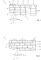
- FIG. 1 a schematic representation of a conventional method for building a three-dimensional component
- Fig. 2 a method according to the invention
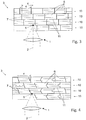
- Fig. 3 a modified version of the method according to Fig. 2
- Fig. 4 another modified embodiment of the method according to Fig. 2
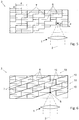
- Fig. 5 another modified embodiment of the method according to Fig. 2
- Fig. 6 another modified embodiment of the method according to Fig. 2
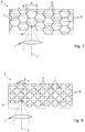
- FIGS. 7 and 8 further modified versions.
- Fig. 1 1 shows schematically an optical unit 1 of an irradiation device in cross section, which has an entry direction 2.
- the entry direction 2 indicates the direction in which the electromagnetic radiation is emitted from the irradiation device onto the component 3 to be formed in the basic setting.
- the irradiation device has a writing area with an extension 4 which corresponds to the width within which the emitted radiation within the material which is solidified by the radiation should, can be focused on focus points 5.
- the irradiation device comprises a unit, not shown in detail, such as a deflection unit. If the named unit is designed to change the direction of irradiation, the term "direction of entry" is to be understood as the main direction of entry of the irradiation device in the basic position.
- the component is constructed from a plurality of partial structures 6 arranged next to one another.
- the procedure here can be such that the substructure 6 is built up from a plurality of layers 9 in the height direction.
- a first partial structure 6 is formed which lies within the writing area of the irradiation device.
- the writing area is shifted laterally by shifting the irradiation device relative to the component 3 or by shifting the component 3 relative to the irradiation device in order to build up a second partial structure 6 next to the first partial structure 6. This is repeated until the finished component 3 has been assembled from all the substructures.
- a component constructed in this way has mechanical weak points at the interfaces 7 between substructures 6 arranged next to one another.
- Fig. 2 it can be seen that the component 3 is built up again from a plurality of substructures 6 according to the method according to the invention, the substructures 6 now not only being arranged next to one another but also one above the other.
- the substructures 6 are arranged in layers 10 arranged one above the other, so that the interface 11 between layers 10 lying one above the other is continuously flat. Because the component 3 is composed not only in the lateral direction but also in the height direction from a plurality of substructures 6, each individual substructure 6 can be formed with a height that is reduced with regard to avoiding shading.
- FIG Fig. 4 various alternative possibilities, namely curved and stepped boundary surfaces 7 which run obliquely to the entry direction 2. This can additionally prevent shading.
- a further modified embodiment is shown, in which the partial structures 6 lying one above the other are not arranged in layers, but rather according to a stepped arrangement.
- the substructures 6 each have a surface on their underside and on their upper side, which has a step at the point at which an interface 7 is provided between below or between substructures above.
- the protruding portion b of the height a of a partial structure 6 that is relevant with regard to shading is lower than in an embodiment according to FIG Fig. 2 so that shading can be avoided even more effectively or the height of the substructures can be increased without increasing the risk of shading.
- Fig. 6 an alternative arrangement of the substructures 6 is shown, the boundary surfaces 11 between superimposed substructures 6 or between the layers 10 now not at right angles to the entry direction 2, but at an angle of max. 45 °, preferably max. 30 ° to the entry direction 2 at an angle.
- Fig. 7 shows a further possibility of the inventive arrangement of the substructures 6.
- the substructures 6 have here on a hexagonal cross-section, so that a honeycomb arrangement results from partial structures arranged side by side and one above the other.
- substructures 6 as in FIGS Figs. 1 to 8 shown are only represented by border lines that indicate that spatial area in which the solidification of the volume elements takes place within the respective substructure without a specific structuring is shown. It goes without saying that in the context of the production of a component of the respectively desired geometry not all volume elements have to be solidified within a partial structure, but that volume areas can remain free within the partial structures.
Landscapes
- Engineering & Computer Science (AREA)
- Chemical & Material Sciences (AREA)
- Materials Engineering (AREA)
- Physics & Mathematics (AREA)
- Optics & Photonics (AREA)
- Manufacturing & Machinery (AREA)
- Mechanical Engineering (AREA)
- Health & Medical Sciences (AREA)
- Toxicology (AREA)
- Plasma & Fusion (AREA)
- General Physics & Mathematics (AREA)
- Materials For Photolithography (AREA)
- Polymerisation Methods In General (AREA)
Priority Applications (10)
| Application Number | Priority Date | Filing Date | Title |
|---|---|---|---|
| LTEP19450004.7T LT3702132T (lt) | 2019-02-26 | 2019-02-26 | Įrenginys ir būdas, skirti trimačio komponento generatyvinei gamybai litografijos pagrindu |
| EP19450004.7A EP3702132B1 (fr) | 2019-02-26 | 2019-02-26 | Procédé de fabrication générative par lithographie de composants tridimensionnels |
| ES19450004T ES2938985T3 (es) | 2019-02-26 | 2019-02-26 | Procedimiento para la fabricación generativa basada en litografía de un componente tridimensional |
| KR1020217030508A KR102723421B1 (ko) | 2019-02-26 | 2020-02-26 | 3차원 구성요소의 리소그래피-기반 생성 제조를 위한 방법 |
| JP2021549914A JP7362756B2 (ja) | 2019-02-26 | 2020-02-26 | リソグラフィを用いた三次元部品の積層造形方法 |
| PCT/IB2020/051626 WO2020174411A1 (fr) | 2019-02-26 | 2020-02-26 | Procédé de préparation générative à base de lithographie d'un composant tridimensionnel |
| US17/431,677 US11787106B2 (en) | 2019-02-26 | 2020-02-26 | Method for the lithography-based additive manufacturing of a three-dimensional component |
| IL285753A IL285753B2 (en) | 2019-02-26 | 2020-02-26 | Method for the lithography-based additive manufacturing of a three-dimensional component |
| CN202080017000.6A CN113453874A (zh) | 2019-02-26 | 2020-02-26 | 用于基于光刻进行三维部件的生成性制造的方法 |
| CA3131320A CA3131320C (fr) | 2019-02-26 | 2020-02-26 | Procede de preparation generative a base de lithographie d'un composant tridimensionnel |
Applications Claiming Priority (1)
| Application Number | Priority Date | Filing Date | Title |
|---|---|---|---|
| EP19450004.7A EP3702132B1 (fr) | 2019-02-26 | 2019-02-26 | Procédé de fabrication générative par lithographie de composants tridimensionnels |
Publications (2)
| Publication Number | Publication Date |
|---|---|
| EP3702132A1 true EP3702132A1 (fr) | 2020-09-02 |
| EP3702132B1 EP3702132B1 (fr) | 2023-01-11 |
Family
ID=65717948
Family Applications (1)
| Application Number | Title | Priority Date | Filing Date |
|---|---|---|---|
| EP19450004.7A Active EP3702132B1 (fr) | 2019-02-26 | 2019-02-26 | Procédé de fabrication générative par lithographie de composants tridimensionnels |
Country Status (10)
| Country | Link |
|---|---|
| US (1) | US11787106B2 (fr) |
| EP (1) | EP3702132B1 (fr) |
| JP (1) | JP7362756B2 (fr) |
| KR (1) | KR102723421B1 (fr) |
| CN (1) | CN113453874A (fr) |
| CA (1) | CA3131320C (fr) |
| ES (1) | ES2938985T3 (fr) |
| IL (1) | IL285753B2 (fr) |
| LT (1) | LT3702132T (fr) |
| WO (1) | WO2020174411A1 (fr) |
Citations (4)
| Publication number | Priority date | Publication date | Assignee | Title |
|---|---|---|---|---|
| DE10111422A1 (de) | 2001-03-09 | 2002-09-26 | Hannover Laser Zentrum | Verfahren und Vorrichtung zur Herstellung eines Formkörpers aus einem durch Bestrahlung zu verfestigenden flüssigen Material |
| EP3093123A1 (fr) | 2015-05-13 | 2016-11-16 | Nanoscribe GmbH | Procede de fabrication d'une structure tridimensionnelle |
| WO2018006108A1 (fr) | 2016-07-07 | 2018-01-11 | Technische Universität Wien | Procédé pour la fabrication générative à base de lithographie de pièces tridimensionnelles |
| DE102017110241A1 (de) * | 2017-05-11 | 2018-11-15 | Nanoscribe Gmbh | Verfahren zum Erzeugen einer 3D-Struktur mittels Laserlithographie sowie Computerprogrammprodukt |
Family Cites Families (16)
| Publication number | Priority date | Publication date | Assignee | Title |
|---|---|---|---|---|
| US5104592A (en) | 1988-04-18 | 1992-04-14 | 3D Systems, Inc. | Method of and apparatus for production of three-dimensional objects by stereolithography with reduced curl |
| US5965079A (en) * | 1995-04-25 | 1999-10-12 | 3D Systems, Inc. | Method and apparatus for making a three-dimensional object by stereolithography |
| US5198159A (en) | 1990-10-09 | 1993-03-30 | Matsushita Electric Works, Ltd. | Process of fabricating three-dimensional objects from a light curable resin liquid |
| US5597520A (en) * | 1990-10-30 | 1997-01-28 | Smalley; Dennis R. | Simultaneous multiple layer curing in stereolithography |
| CA2326322C (fr) | 1998-04-21 | 2011-03-01 | University Of Connecticut | Nanofabrication a structure libre utilisant une excitation multiphotonique |
| US7931851B2 (en) * | 2003-09-11 | 2011-04-26 | Nabtesco Corporation | Stereolithographic method and apparatus |
| DE102013005565A1 (de) | 2013-03-28 | 2014-10-02 | Karlsruher Institut für Technologie | Herstellung von 3D-Freiform-Wellenleiterstrukturen |
| JP6022493B2 (ja) * | 2014-02-13 | 2016-11-09 | シーメット株式会社 | 光造形方法、光造形装置、及び生成プログラム |
| DE102014221480B4 (de) | 2014-10-22 | 2017-10-05 | Nanoscribe Gmbh | Verfahren zum Herstellen einer dreidimensionalen Struktur |
| US9981312B2 (en) * | 2015-05-11 | 2018-05-29 | Wisconsin Alumni Research Foundation | Three-dimension printer with mechanically scanned cathode-comb |
| JP6724303B2 (ja) * | 2015-07-22 | 2020-07-15 | 株式会社リコー | 立体造形物の製造方法 |
| EP3135459A1 (fr) * | 2015-08-31 | 2017-03-01 | Nederlandse Organisatie voor toegepast- natuurwetenschappelijk onderzoek TNO | Procédé et système pour la production de couches d'un objet tangible |
| US11278988B2 (en) * | 2015-12-17 | 2022-03-22 | Eos Of North America, Inc. | Additive manufacturing method using large and small beam sizes |
| JP6944935B2 (ja) | 2015-12-22 | 2021-10-06 | カーボン,インコーポレイテッド | 二重硬化樹脂を用いた積層造形による複数の中間体からの複合生産物の製作 |
| DE102017205051A1 (de) * | 2017-03-24 | 2018-09-27 | Eos Gmbh Electro Optical Systems | Überlappoptimierung |
| CN108927993B (zh) * | 2017-05-26 | 2020-12-15 | 三纬国际立体列印科技股份有限公司 | 多光源模块的光固化3d打印方法 |
-
2019
- 2019-02-26 ES ES19450004T patent/ES2938985T3/es active Active
- 2019-02-26 LT LTEP19450004.7T patent/LT3702132T/lt unknown
- 2019-02-26 EP EP19450004.7A patent/EP3702132B1/fr active Active
-
2020
- 2020-02-26 CN CN202080017000.6A patent/CN113453874A/zh active Pending
- 2020-02-26 IL IL285753A patent/IL285753B2/en unknown
- 2020-02-26 CA CA3131320A patent/CA3131320C/fr active Active
- 2020-02-26 JP JP2021549914A patent/JP7362756B2/ja active Active
- 2020-02-26 KR KR1020217030508A patent/KR102723421B1/ko active Active
- 2020-02-26 WO PCT/IB2020/051626 patent/WO2020174411A1/fr not_active Ceased
- 2020-02-26 US US17/431,677 patent/US11787106B2/en active Active
Patent Citations (4)
| Publication number | Priority date | Publication date | Assignee | Title |
|---|---|---|---|---|
| DE10111422A1 (de) | 2001-03-09 | 2002-09-26 | Hannover Laser Zentrum | Verfahren und Vorrichtung zur Herstellung eines Formkörpers aus einem durch Bestrahlung zu verfestigenden flüssigen Material |
| EP3093123A1 (fr) | 2015-05-13 | 2016-11-16 | Nanoscribe GmbH | Procede de fabrication d'une structure tridimensionnelle |
| WO2018006108A1 (fr) | 2016-07-07 | 2018-01-11 | Technische Universität Wien | Procédé pour la fabrication générative à base de lithographie de pièces tridimensionnelles |
| DE102017110241A1 (de) * | 2017-05-11 | 2018-11-15 | Nanoscribe Gmbh | Verfahren zum Erzeugen einer 3D-Struktur mittels Laserlithographie sowie Computerprogrammprodukt |
Non-Patent Citations (1)
| Title |
|---|
| ZIPFEL ET AL.: "Nonlinear magic: multiphoton microscopy in the biosciences", NATURE BIOTECHNOLOGY, vol. 21, no. 11, November 2003 (2003-11-01), XP002444341, DOI: doi:10.1038/nbt899 |
Also Published As
| Publication number | Publication date |
|---|---|
| IL285753A (en) | 2021-10-31 |
| CN113453874A (zh) | 2021-09-28 |
| IL285753B1 (en) | 2024-11-01 |
| JP2022521626A (ja) | 2022-04-11 |
| IL285753B2 (en) | 2025-03-01 |
| ES2938985T3 (es) | 2023-04-18 |
| CA3131320A1 (fr) | 2020-09-03 |
| KR20210131390A (ko) | 2021-11-02 |
| KR102723421B1 (ko) | 2024-10-28 |
| JP7362756B2 (ja) | 2023-10-17 |
| CA3131320C (fr) | 2023-10-31 |
| LT3702132T (lt) | 2023-02-27 |
| US11787106B2 (en) | 2023-10-17 |
| US20220118691A1 (en) | 2022-04-21 |
| WO2020174411A1 (fr) | 2020-09-03 |
| EP3702132B1 (fr) | 2023-01-11 |
Similar Documents
| Publication | Publication Date | Title |
|---|---|---|
| EP3383624B1 (fr) | Procédé d'étalonnage d'un dispositif de fabrication d'un objet tridimensionnel | |
| EP2864108B1 (fr) | Dispositif et procédé de fabrication par couches d'un objet tridimensionnel | |
| DE102017202725B3 (de) | Vorrichtung und Verfahren zum Kalibrieren eines Bestrahlungssystems, das zum Herstellen eines dreidimensionalen Werkstücks verwendet wird | |
| EP3266594B1 (fr) | Procédé et dispositif de fabrication générative par lithographie de composants tridimensionnels | |
| DE19915000C2 (de) | Vorrichtung und Verfahren zum Steuern der Intensitätsverteilung eines Laserstrahls | |
| EP3242762A1 (fr) | Dispositif et procédé génératif de construction par couches permettant de produire un objet tridimensionnel au moyen d'une pluralité de rayons | |
| EP3022044B1 (fr) | Procédé et dispositif de fabrication d'un objet en trois dimensions ainsi que système de génération de masques d'exposition | |
| EP1419836A1 (fr) | Procédé de fabrication d'un objet, en particulier par stereolithografie ou frittage | |
| EP3934833A1 (fr) | Procédé de commande, système de commande et dispositif de fabrication | |
| EP3538293B1 (fr) | Procédé de fabrication additive des produits en couche et logiciel correspondant | |
| EP3648955A1 (fr) | Procédé optimisé de segmentation | |
| EP2983898A1 (fr) | Procédé d'étalonnage automatique d'un dispositif de fabrication additive d'un objet tridimensionnel | |
| EP1993812A1 (fr) | Procédé et dispositif de production d'un objet tridimensionnel | |
| DE102016107058A1 (de) | 3D-Druck-Vorrichtung für die Herstellung eines räumlich ausgedehnten Produkts | |
| EP3866999A1 (fr) | Procédé et dispositif de fabrication d'une pièce tridimensionnelle | |
| EP3022045B1 (fr) | Procédé et dispositif de fabrication d'un objet en trois dimensions ainsi que système de production de masques d'exposition | |
| EP3698225A1 (fr) | Procédé et dispositif de préparation d'un jeu d'instructions de commande | |
| EP4163083B1 (fr) | Procédé et dispositif de fabrication additive par lithographie d'un composant tridimensionnel | |
| DE102018205688A1 (de) | Verfahren und Vorrichtung zur Verbesserung der Bauteilqualität von durch ein additives Herstellverfahren hergestellten Objekten | |
| EP3568258B1 (fr) | Procédé de réduction ou de fermeture totale d'une ouverture d'un contour intérieur d'une pièce à usiner au moyen d'une matière fondue par un dispositif de rechargement laser | |
| EP3888887B1 (fr) | Procédé et dispositif de fabrication additive par lithographie d'un composant tridimensionnel | |
| EP3702132B1 (fr) | Procédé de fabrication générative par lithographie de composants tridimensionnels | |
| DE102020126269B4 (de) | Vorrichtung und Verfahren zum Erzeugen einer definierten Laserlinie auf einer Arbeitsebene | |
| DE4416901A1 (de) | Vorrichtung und Verfahren zum Herstellen eines dreidimensionalen Objekts | |
| DE112022001278T5 (de) | Laserverarbeitungsvorrichtung und Laserverarbeitungsverfahren |
Legal Events
| Date | Code | Title | Description |
|---|---|---|---|
| PUAI | Public reference made under article 153(3) epc to a published international application that has entered the european phase |
Free format text: ORIGINAL CODE: 0009012 |
|
| STAA | Information on the status of an ep patent application or granted ep patent |
Free format text: STATUS: THE APPLICATION HAS BEEN PUBLISHED |
|
| AK | Designated contracting states |
Kind code of ref document: A1 Designated state(s): AL AT BE BG CH CY CZ DE DK EE ES FI FR GB GR HR HU IE IS IT LI LT LU LV MC MK MT NL NO PL PT RO RS SE SI SK SM TR |
|
| AX | Request for extension of the european patent |
Extension state: BA ME |
|
| STAA | Information on the status of an ep patent application or granted ep patent |
Free format text: STATUS: REQUEST FOR EXAMINATION WAS MADE |
|
| 17P | Request for examination filed |
Effective date: 20210302 |
|
| RBV | Designated contracting states (corrected) |
Designated state(s): AL AT BE BG CH CY CZ DE DK EE ES FI FR GB GR HR HU IE IS IT LI LT LU LV MC MK MT NL NO PL PT RO RS SE SI SK SM TR |
|
| STAA | Information on the status of an ep patent application or granted ep patent |
Free format text: STATUS: EXAMINATION IS IN PROGRESS |
|
| 17Q | First examination report despatched |
Effective date: 20211108 |
|
| RIN1 | Information on inventor provided before grant (corrected) |
Inventor name: GRUBER, PETER |
|
| GRAP | Despatch of communication of intention to grant a patent |
Free format text: ORIGINAL CODE: EPIDOSNIGR1 |
|
| STAA | Information on the status of an ep patent application or granted ep patent |
Free format text: STATUS: GRANT OF PATENT IS INTENDED |
|
| GRAS | Grant fee paid |
Free format text: ORIGINAL CODE: EPIDOSNIGR3 |
|
| INTG | Intention to grant announced |
Effective date: 20221110 |
|
| GRAA | (expected) grant |
Free format text: ORIGINAL CODE: 0009210 |
|
| STAA | Information on the status of an ep patent application or granted ep patent |
Free format text: STATUS: THE PATENT HAS BEEN GRANTED |
|
| AK | Designated contracting states |
Kind code of ref document: B1 Designated state(s): AL AT BE BG CH CY CZ DE DK EE ES FI FR GB GR HR HU IE IS IT LI LT LU LV MC MK MT NL NO PL PT RO RS SE SI SK SM TR |
|
| REG | Reference to a national code |
Ref country code: GB Ref legal event code: FG4D Free format text: NOT ENGLISH |
|
| REG | Reference to a national code |
Ref country code: CH Ref legal event code: EP |
|
| REG | Reference to a national code |
Ref country code: DE Ref legal event code: R096 Ref document number: 502019006763 Country of ref document: DE |
|
| REG | Reference to a national code |
Ref country code: IE Ref legal event code: FG4D Free format text: LANGUAGE OF EP DOCUMENT: GERMAN |
|
| REG | Reference to a national code |
Ref country code: AT Ref legal event code: REF Ref document number: 1543166 Country of ref document: AT Kind code of ref document: T Effective date: 20230215 |
|
| REG | Reference to a national code |
Ref country code: NL Ref legal event code: FP |
|
| REG | Reference to a national code |
Ref country code: ES Ref legal event code: FG2A Ref document number: 2938985 Country of ref document: ES Kind code of ref document: T3 Effective date: 20230418 |
|
| P01 | Opt-out of the competence of the unified patent court (upc) registered |
Effective date: 20230515 |
|
| PG25 | Lapsed in a contracting state [announced via postgrant information from national office to epo] |
Ref country code: RS Free format text: LAPSE BECAUSE OF FAILURE TO SUBMIT A TRANSLATION OF THE DESCRIPTION OR TO PAY THE FEE WITHIN THE PRESCRIBED TIME-LIMIT Effective date: 20230111 Ref country code: PT Free format text: LAPSE BECAUSE OF FAILURE TO SUBMIT A TRANSLATION OF THE DESCRIPTION OR TO PAY THE FEE WITHIN THE PRESCRIBED TIME-LIMIT Effective date: 20230511 Ref country code: NO Free format text: LAPSE BECAUSE OF FAILURE TO SUBMIT A TRANSLATION OF THE DESCRIPTION OR TO PAY THE FEE WITHIN THE PRESCRIBED TIME-LIMIT Effective date: 20230411 Ref country code: LV Free format text: LAPSE BECAUSE OF FAILURE TO SUBMIT A TRANSLATION OF THE DESCRIPTION OR TO PAY THE FEE WITHIN THE PRESCRIBED TIME-LIMIT Effective date: 20230111 Ref country code: HR Free format text: LAPSE BECAUSE OF FAILURE TO SUBMIT A TRANSLATION OF THE DESCRIPTION OR TO PAY THE FEE WITHIN THE PRESCRIBED TIME-LIMIT Effective date: 20230111 |
|
| PG25 | Lapsed in a contracting state [announced via postgrant information from national office to epo] |
Ref country code: SE Free format text: LAPSE BECAUSE OF FAILURE TO SUBMIT A TRANSLATION OF THE DESCRIPTION OR TO PAY THE FEE WITHIN THE PRESCRIBED TIME-LIMIT Effective date: 20230111 Ref country code: PL Free format text: LAPSE BECAUSE OF FAILURE TO SUBMIT A TRANSLATION OF THE DESCRIPTION OR TO PAY THE FEE WITHIN THE PRESCRIBED TIME-LIMIT Effective date: 20230111 Ref country code: IS Free format text: LAPSE BECAUSE OF FAILURE TO SUBMIT A TRANSLATION OF THE DESCRIPTION OR TO PAY THE FEE WITHIN THE PRESCRIBED TIME-LIMIT Effective date: 20230511 Ref country code: GR Free format text: LAPSE BECAUSE OF FAILURE TO SUBMIT A TRANSLATION OF THE DESCRIPTION OR TO PAY THE FEE WITHIN THE PRESCRIBED TIME-LIMIT Effective date: 20230412 Ref country code: FI Free format text: LAPSE BECAUSE OF FAILURE TO SUBMIT A TRANSLATION OF THE DESCRIPTION OR TO PAY THE FEE WITHIN THE PRESCRIBED TIME-LIMIT Effective date: 20230111 |
|
| REG | Reference to a national code |
Ref country code: DE Ref legal event code: R026 Ref document number: 502019006763 Country of ref document: DE |
|
| PLBI | Opposition filed |
Free format text: ORIGINAL CODE: 0009260 |
|
| PLAX | Notice of opposition and request to file observation + time limit sent |
Free format text: ORIGINAL CODE: EPIDOSNOBS2 |
|
| PG25 | Lapsed in a contracting state [announced via postgrant information from national office to epo] |
Ref country code: SM Free format text: LAPSE BECAUSE OF FAILURE TO SUBMIT A TRANSLATION OF THE DESCRIPTION OR TO PAY THE FEE WITHIN THE PRESCRIBED TIME-LIMIT Effective date: 20230111 Ref country code: RO Free format text: LAPSE BECAUSE OF FAILURE TO SUBMIT A TRANSLATION OF THE DESCRIPTION OR TO PAY THE FEE WITHIN THE PRESCRIBED TIME-LIMIT Effective date: 20230111 Ref country code: MC Free format text: LAPSE BECAUSE OF FAILURE TO SUBMIT A TRANSLATION OF THE DESCRIPTION OR TO PAY THE FEE WITHIN THE PRESCRIBED TIME-LIMIT Effective date: 20230111 Ref country code: LU Free format text: LAPSE BECAUSE OF NON-PAYMENT OF DUE FEES Effective date: 20230226 Ref country code: EE Free format text: LAPSE BECAUSE OF FAILURE TO SUBMIT A TRANSLATION OF THE DESCRIPTION OR TO PAY THE FEE WITHIN THE PRESCRIBED TIME-LIMIT Effective date: 20230111 Ref country code: DK Free format text: LAPSE BECAUSE OF FAILURE TO SUBMIT A TRANSLATION OF THE DESCRIPTION OR TO PAY THE FEE WITHIN THE PRESCRIBED TIME-LIMIT Effective date: 20230111 Ref country code: CZ Free format text: LAPSE BECAUSE OF FAILURE TO SUBMIT A TRANSLATION OF THE DESCRIPTION OR TO PAY THE FEE WITHIN THE PRESCRIBED TIME-LIMIT Effective date: 20230111 |
|
| 26 | Opposition filed |
Opponent name: NANOSCRIBE HOLDING GMBH Effective date: 20231009 |
|
| PG25 | Lapsed in a contracting state [announced via postgrant information from national office to epo] |
Ref country code: SK Free format text: LAPSE BECAUSE OF FAILURE TO SUBMIT A TRANSLATION OF THE DESCRIPTION OR TO PAY THE FEE WITHIN THE PRESCRIBED TIME-LIMIT Effective date: 20230111 |
|
| REG | Reference to a national code |
Ref country code: IE Ref legal event code: MM4A |
|
| PG25 | Lapsed in a contracting state [announced via postgrant information from national office to epo] |
Ref country code: SI Free format text: LAPSE BECAUSE OF FAILURE TO SUBMIT A TRANSLATION OF THE DESCRIPTION OR TO PAY THE FEE WITHIN THE PRESCRIBED TIME-LIMIT Effective date: 20230111 Ref country code: IE Free format text: LAPSE BECAUSE OF NON-PAYMENT OF DUE FEES Effective date: 20230226 |
|
| PLBB | Reply of patent proprietor to notice(s) of opposition received |
Free format text: ORIGINAL CODE: EPIDOSNOBS3 |
|
| PG25 | Lapsed in a contracting state [announced via postgrant information from national office to epo] |
Ref country code: BG Free format text: LAPSE BECAUSE OF FAILURE TO SUBMIT A TRANSLATION OF THE DESCRIPTION OR TO PAY THE FEE WITHIN THE PRESCRIBED TIME-LIMIT Effective date: 20230111 |
|
| PG25 | Lapsed in a contracting state [announced via postgrant information from national office to epo] |
Ref country code: BG Free format text: LAPSE BECAUSE OF FAILURE TO SUBMIT A TRANSLATION OF THE DESCRIPTION OR TO PAY THE FEE WITHIN THE PRESCRIBED TIME-LIMIT Effective date: 20230111 |
|
| PG25 | Lapsed in a contracting state [announced via postgrant information from national office to epo] |
Ref country code: CY Free format text: LAPSE BECAUSE OF FAILURE TO SUBMIT A TRANSLATION OF THE DESCRIPTION OR TO PAY THE FEE WITHIN THE PRESCRIBED TIME-LIMIT; INVALID AB INITIO Effective date: 20190226 |
|
| PG25 | Lapsed in a contracting state [announced via postgrant information from national office to epo] |
Ref country code: HU Free format text: LAPSE BECAUSE OF FAILURE TO SUBMIT A TRANSLATION OF THE DESCRIPTION OR TO PAY THE FEE WITHIN THE PRESCRIBED TIME-LIMIT; INVALID AB INITIO Effective date: 20190226 |
|
| PG25 | Lapsed in a contracting state [announced via postgrant information from national office to epo] |
Ref country code: TR Free format text: LAPSE BECAUSE OF FAILURE TO SUBMIT A TRANSLATION OF THE DESCRIPTION OR TO PAY THE FEE WITHIN THE PRESCRIBED TIME-LIMIT Effective date: 20230111 |
|
| REG | Reference to a national code |
Ref country code: CH Ref legal event code: U11 Free format text: ST27 STATUS EVENT CODE: U-0-0-U10-U11 (AS PROVIDED BY THE NATIONAL OFFICE) Effective date: 20260301 |
|
| PGFP | Annual fee paid to national office [announced via postgrant information from national office to epo] |
Ref country code: NL Payment date: 20260218 Year of fee payment: 8 |
|
| PGFP | Annual fee paid to national office [announced via postgrant information from national office to epo] |
Ref country code: GB Payment date: 20260219 Year of fee payment: 8 Ref country code: LT Payment date: 20260217 Year of fee payment: 8 |
|
| PGFP | Annual fee paid to national office [announced via postgrant information from national office to epo] |
Ref country code: ES Payment date: 20260319 Year of fee payment: 8 |
|
| PGFP | Annual fee paid to national office [announced via postgrant information from national office to epo] |
Ref country code: DE Payment date: 20260217 Year of fee payment: 8 |
|
| PGFP | Annual fee paid to national office [announced via postgrant information from national office to epo] |
Ref country code: AT Payment date: 20260210 Year of fee payment: 8 |
|
| PGFP | Annual fee paid to national office [announced via postgrant information from national office to epo] |
Ref country code: BE Payment date: 20260218 Year of fee payment: 8 Ref country code: IT Payment date: 20260227 Year of fee payment: 8 |
|
| PGFP | Annual fee paid to national office [announced via postgrant information from national office to epo] |
Ref country code: FR Payment date: 20260219 Year of fee payment: 8 |
|
| PGFP | Annual fee paid to national office [announced via postgrant information from national office to epo] |
Ref country code: CH Payment date: 20260301 Year of fee payment: 8 |