EP3702176A1 - Pneumatique - Google Patents
Pneumatique Download PDFInfo
- Publication number
- EP3702176A1 EP3702176A1 EP20159611.1A EP20159611A EP3702176A1 EP 3702176 A1 EP3702176 A1 EP 3702176A1 EP 20159611 A EP20159611 A EP 20159611A EP 3702176 A1 EP3702176 A1 EP 3702176A1
- Authority
- EP
- European Patent Office
- Prior art keywords
- tire
- shoulder
- tread
- groove
- grooves
- Prior art date
- Legal status (The legal status is an assumption and is not a legal conclusion. Google has not performed a legal analysis and makes no representation as to the accuracy of the status listed.)
- Granted
Links
Images

Classifications
-
- B—PERFORMING OPERATIONS; TRANSPORTING
- B60—VEHICLES IN GENERAL
- B60C—VEHICLE TYRES; TYRE INFLATION; TYRE CHANGING; CONNECTING VALVES TO INFLATABLE ELASTIC BODIES IN GENERAL; DEVICES OR ARRANGEMENTS RELATED TO TYRES
- B60C11/00—Tyre tread bands; Tread patterns; Anti-skid inserts
- B60C11/03—Tread patterns
- B60C11/0302—Tread patterns directional pattern, i.e. with main rolling direction
-
- B—PERFORMING OPERATIONS; TRANSPORTING
- B60—VEHICLES IN GENERAL
- B60C—VEHICLE TYRES; TYRE INFLATION; TYRE CHANGING; CONNECTING VALVES TO INFLATABLE ELASTIC BODIES IN GENERAL; DEVICES OR ARRANGEMENTS RELATED TO TYRES
- B60C11/00—Tyre tread bands; Tread patterns; Anti-skid inserts
- B60C11/03—Tread patterns
- B60C11/0327—Tread patterns characterised by special properties of the tread pattern
- B60C11/033—Tread patterns characterised by special properties of the tread pattern by the void or net-to-gross ratios of the patterns
-
- B—PERFORMING OPERATIONS; TRANSPORTING
- B60—VEHICLES IN GENERAL
- B60C—VEHICLE TYRES; TYRE INFLATION; TYRE CHANGING; CONNECTING VALVES TO INFLATABLE ELASTIC BODIES IN GENERAL; DEVICES OR ARRANGEMENTS RELATED TO TYRES
- B60C11/00—Tyre tread bands; Tread patterns; Anti-skid inserts
- B60C11/03—Tread patterns
- B60C11/12—Tread patterns characterised by the use of narrow slits or incisions, e.g. sipes
- B60C11/1236—Tread patterns characterised by the use of narrow slits or incisions, e.g. sipes with special arrangements in the tread pattern
-
- B—PERFORMING OPERATIONS; TRANSPORTING
- B60—VEHICLES IN GENERAL
- B60C—VEHICLE TYRES; TYRE INFLATION; TYRE CHANGING; CONNECTING VALVES TO INFLATABLE ELASTIC BODIES IN GENERAL; DEVICES OR ARRANGEMENTS RELATED TO TYRES
- B60C11/00—Tyre tread bands; Tread patterns; Anti-skid inserts
- B60C11/03—Tread patterns
- B60C11/12—Tread patterns characterised by the use of narrow slits or incisions, e.g. sipes
- B60C11/1259—Depth of the sipe
-
- B—PERFORMING OPERATIONS; TRANSPORTING
- B60—VEHICLES IN GENERAL
- B60C—VEHICLE TYRES; TYRE INFLATION; TYRE CHANGING; CONNECTING VALVES TO INFLATABLE ELASTIC BODIES IN GENERAL; DEVICES OR ARRANGEMENTS RELATED TO TYRES
- B60C11/00—Tyre tread bands; Tread patterns; Anti-skid inserts
- B60C11/03—Tread patterns
- B60C2011/0337—Tread patterns characterised by particular design features of the pattern
- B60C2011/0339—Grooves
- B60C2011/0341—Circumferential grooves
-
- B—PERFORMING OPERATIONS; TRANSPORTING
- B60—VEHICLES IN GENERAL
- B60C—VEHICLE TYRES; TYRE INFLATION; TYRE CHANGING; CONNECTING VALVES TO INFLATABLE ELASTIC BODIES IN GENERAL; DEVICES OR ARRANGEMENTS RELATED TO TYRES
- B60C11/00—Tyre tread bands; Tread patterns; Anti-skid inserts
- B60C11/03—Tread patterns
- B60C2011/0337—Tread patterns characterised by particular design features of the pattern
- B60C2011/0339—Grooves
- B60C2011/0381—Blind or isolated grooves
-
- B—PERFORMING OPERATIONS; TRANSPORTING
- B60—VEHICLES IN GENERAL
- B60C—VEHICLE TYRES; TYRE INFLATION; TYRE CHANGING; CONNECTING VALVES TO INFLATABLE ELASTIC BODIES IN GENERAL; DEVICES OR ARRANGEMENTS RELATED TO TYRES
- B60C11/00—Tyre tread bands; Tread patterns; Anti-skid inserts
- B60C11/03—Tread patterns
- B60C2011/0337—Tread patterns characterised by particular design features of the pattern
- B60C2011/0386—Continuous ribs
Definitions
- the present invention relates to a tire.
- the tire proposed in Japanese Laid-Open Patent Publication No. 2015-171872 includes: straight ribs that are disposed at the center side of a tread and that continuously extend in a straight manner in the tire circumferential direction; and middle blocks connected to the straight ribs.
- the middle blocks are demarcated by inclined lateral grooves. In the tire, falling of the middle blocks is inhibited by the straight ribs, whereby a decrease in the groove volumes of the inclined lateral grooves is prevented, and improvement of wet performance is further expected.
- the present invention has been made in view of the above-described problem, and a main object of the present invention is to provide a tire having improved wet performance and steering stability.
- a first aspect of the present invention provides a tire including a tread portion, wherein: the tread portion is divided into five land portions by four main grooves continuously extending in a tire circumferential direction; the four main grooves include two shoulder main grooves provided between two tread edges, and two crown main grooves provided between the two shoulder main grooves; the five land portions include two shoulder land portions each demarcated between the tread edge and the shoulder main groove, two middle land portions each demarcated between the shoulder main groove and the crown main groove, and one crown land portion demarcated between the two crown main grooves; each of the middle land portions has a plurality of middle lateral grooves that extend from the shoulder main groove and that terminate within the middle land portion; each of the middle land portions is a semi-block row including a rib region continuously extending in the tire circumferential direction at an inner side in a tire axial direction with respect to the plurality of middle lateral grooves, and a block region divided by the plurality of middle lateral grooves; each of the shoulder land portions is a block row divided by a
- the total area S1 is 14.0% to 17.0% of a total area St of a virtual tread surface obtained by filling all grooves and sipes provided on a tread surface of the tread portion.
- the total area S2 is 11.0% to 14.0% of a total area St of a virtual tread surface obtained by filling all grooves and sipes provided on a tread surface of the tread portion.
- the crown land portion is a rib continuously extending in the tire circumferential direction.
- a total area S3 of a tread surface of the crown land portion is 4.0% to 10.0% of a total area St of a virtual tread surface obtained by filling all grooves and sipes provided on a tread surface of the tread portion.
- the rib region has a plurality of sipes.
- a distance in the tire axial direction from a tire equator to a groove center line of each shoulder main groove is 0.25 to 0.31 times a tread width.
- each of the shoulder land portions has a shoulder short groove that extends from the tread edge and that terminates within the shoulder land portion.
- the tread portion has a designated rotational direction, and, in a transverse cross-section of each of the middle lateral grooves, a groove wall at a toe side in the rotational direction of the middle lateral groove includes a main body portion that extends in a tire radial direction from a bottom portion, and a chamfered portion that extends at a larger angle relative to the tire radial direction than the main body portion.
- a groove wall at a heel side in the rotational direction of the middle lateral groove extends from the bottom portion to a groove edge at a constant angle relative to the tire radial direction.
- a second aspect of the present invention provides a tire including a tread portion, wherein: the tread portion is divided into six land portions by five main grooves continuously extending in a tire circumferential direction; the five main grooves include two shoulder main grooves provided between two tread edges, and three crown main grooves provided between the two shoulder main grooves; the six land portions include two shoulder land portions each demarcated between the tread edge and the shoulder main groove, two middle land portions each demarcated between the shoulder main groove and the crown main groove, and two crown land portions each demarcated between the two crown main grooves; each of the middle land portions has a plurality of middle lateral grooves that extend from the shoulder main groove and that terminate within the middle land portion; each of the middle land portions is a semi-block row including a rib region continuously extending in the tire circumferential direction at an inner side in a tire axial direction with respect to the plurality of middle lateral grooves, and a block region divided by the plurality of middle lateral grooves; each of the shoulder land portions is a block row divided by
- a total area S4 of a tread surface of one of the crown land portions is not less than 3.0% of a total area St of a virtual tread surface obtained by filling all grooves and sipes provided on a tread surface of the tread portion.
- Each middle land portion of the tire according to the present invention is a semi-block row including a rib region continuously extending in the tire circumferential direction at the inner side in the tire axial direction with respect to the plurality of middle lateral grooves, and a block region divided by the plurality of middle lateral grooves.
- each shoulder land portion is a block row divided by a plurality of shoulder lateral grooves extending from the shoulder main groove to the tread edge.
- the rib region has high stiffness and serves to enhance steering stability on a dry road surface.
- the middle lateral grooves and the shoulder lateral grooves discharge water pushed aside by the rib region, to the tread edge side during running on a wet road surface, and exhibit excellent wet performance.
- the total area S1 of the tread surface of each of the shoulder land portions is larger than the total area S2 of the tread surface of the middle land portion adjacent thereto via the shoulder main groove. Accordingly, the stiffness of the shoulder land portion is increased, so that steering stability during cornering is improved.
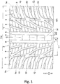
- FIG. 1 shows a development of a tread portion 2 of a tire 1 according to the present embodiment.
- the tire 1 of the present embodiment is used, for example, as a pneumatic tire for a passenger car.
- the tire 1 of the present embodiment is suitably used as a rain tire for racing on a circuit.
- the tire 1 of the present embodiment has, for example, a tread width of 300 to 350 mm, an outer diameter of 700 to 730 mm, and a rim diameter of 17 to 19 inches and is used in so-called touring car races.
- the tire of the present invention is not limited to such a mode.
- the tire 1 of the present embodiment has, for example, a designated rotational direction R.
- the rotational direction R is indicated, for example, on a sidewall portion (not shown) by characters or symbols.
- the tread portion 2 is divided into five land portions 4 by four main grooves 3 continuously extending in the tire circumferential direction.
- the tread portion 2 of the present embodiment has a pattern that is in line symmetry with respect to a tire equator C.
- the tread portion 2 is divided into six land portions 4 by five main grooves 3 continuously extending in the tire circumferential direction. A further specific configuration of the second embodiment of the present invention will be described later.
- the four main grooves 3 include two shoulder main grooves 5 and two crown main grooves 6.
- the two shoulder main grooves 5 are provided between two tread edges Te.
- the two crown main grooves 6 are provided between the two shoulder main grooves 5.
- the tread edges Te are ground contact positions at the outermost side in the tire axial direction when a normal load is applied to the tire 1, in a normal state where the tire 1 is mounted to a normal rim and inflated to a normal internal pressure and no load is applied to the tire 1, such that the tire 1 is brought into contact with a flat surface at a camber angle of 0 degrees.
- dimensions and the like of components of the tire are values measured in the normal state.
- the "normal rim” is a rim that is defined, in a standard system including a standard on which the tire is based, by the standard for each tire, and is, for example, the "standard rim” in the JATMA standard, the "Design Rim” in the TRA standard, or the “Measuring Rim” in the ETRTO standard.
- the "normal internal pressure” is an air pressure that is defined, in a standard system including a standard on which the tire is based, by the standard for each tire, and is the “maximum air pressure” in the JATMA standard, the maximum value indicated in the table "TIRE LOAD LIMITS AT VARIOUS COLD INFLATION PRESSURES" in the TRA standard, or the “INFLATION PRESSURE” in the ETRTO standard.
- the "normal load” is a load that is defined, in a standard system including a standard on which the tire is based, by the standard for each tire, and is the “maximum load capacity" in the JATMA standard, the maximum value indicated in the table "TIRE LOAD LIMITS AT VARIOUS COLD INFLATION PRESSURES" in the TRA standard, or the "LOAD CAPACITY" in the ETRTO standard.
- the tread edges Te are defined, for example, as ground contact positions at the outermost side in the tire axial direction when a standard high load corresponding to the tire category is applied to the tire, in a standard use state, such that the tire is brought into contact with a flat surface at a camber angle of 0 degrees.
- the “standard use state” refers to at least a state where the purpose of use of the tire can be achieved, and refers to, for example, a state where the tire is mounted to a rim recommended by the manufacturer and inflated to an internal pressure recommended by the manufacturer and no load is applied to the tire.
- the "standard high load” is a load assuming a vertical load acting on the front wheel tire at the outer side of cornering during sharp cornering, and is set, for example, to be 70 times the weight of the tire 1 (excluding the rim).
- ground contact positions at the outermost side in the tire axial direction when the tire is inflated to an internal pressure of 200 kPa, the tire is brought into contact with a flat surface at a camber angle of 0 degrees, and a vertical load of 800 kg is applied to the tire may be regarded as the tread edges Te.
- Each of the shoulder main grooves 5 preferably extends, for example, in a zigzag manner.
- Each of the shoulder main grooves 5 of the present embodiment includes, for example, gently inclined portions 5a that are inclined at an angle of 5 to 15° relative to the tire circumferential direction.
- Each of the crown main grooves 6 preferably extends, for example, parallel to the tire circumferential direction in a straight manner.
- the distance L1 in the tire axial direction from the tire equator C to a groove center line of the shoulder main groove 5 is, for example, 0.20 to 0.35 times and preferably 0.25 to 0.31 times a tread width TW.
- the distance L2 in the tire axial direction from the tire equator C to a groove center line of the crown main groove 6 is, for example, preferably 0.05 to 0.10 times the tread width TW.
- the tread width TW is the distance in the tire axial direction from one tread edge Te to the other tread edge Te in the normal state or the standard use state.
- the groove width W1 of the shoulder main groove 5 is, for example, 2.5% to 4.5% of the tread width TW.
- the groove width W2 of the crown main groove 6 is, for example, 4.0% to 7.0% of the tread width TW.
- each of the groove depths of the shoulder main groove 5 and the crown main groove 6 is, for example, preferably 5 to 10 mm.
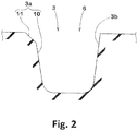
- FIG. 2 shows a transverse cross-section of the crown main groove 6 as an example of a transverse cross-section of the main groove 3.
- a groove wall 3a at the tread edge Te side of the main groove 3 includes a main body portion 10 that extends in the tire radial direction from a bottom portion, and a chamfered portion 11 that extends at a larger angle relative to the tire radial direction than the main body portion 10.
- a groove wall 3b at the tire equator C side of the main groove 3 extends from the bottom portion to the groove edge at a constant angle relative to the tire radial direction.
- Such a main groove 3 serves to exhibit excellent wet performance.
- the five land portions 4 include two shoulder land portions 7, two middle land portions 8, and one crown land portion 9.
- Each shoulder land portion 7 is demarcated between the tread edge Te and the shoulder main groove 5.
- Each middle land portion 8 is demarcated between the shoulder main groove 5 and the crown main groove 6.
- the crown land portion 9 is demarcated between the two crown main grooves 6.
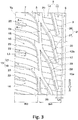
- FIG. 3 shows an enlarged view of the middle land portion 8 and the shoulder land portion 7.
- each middle land portion 8 has a plurality of middle lateral grooves 12.
- Each middle lateral groove 12 extends from the shoulder main groove 5 and terminates within the middle land portion 8.
- the middle land portion 8 is a semi-block row including: a rib region 13 that continuously extends in the tire circumferential direction at the inner side in the tire axial direction with respect to the plurality of middle lateral grooves 12; and a block region 14 divided by the plurality of middle lateral grooves 12.
- the rib region 13 continuously extending in the tire circumferential direction means a region that is not divided in the tire circumferential direction by a transverse groove having a width greater than 1.5 mm.
- a sipe having a width equal to or less than 1.5 mm may traverse the rib region 13.
- Each of the shoulder land portions 7 has a plurality of shoulder lateral grooves 15.
- Each shoulder lateral groove 15 extends from the shoulder main groove 5 to the tread edge Te.
- the shoulder land portion 7 is a block row including a plurality of shoulder blocks 16 demarcated by the plurality of shoulder lateral grooves 15.
- the rib region 13 has high stiffness and serves to enhance steering stability on a dry road surface.
- the middle lateral grooves 12 and the shoulder lateral grooves 15 discharge water pushed aside by the rib region 13, toward the tread edge side during running on a wet road surface, and exhibit excellent wet performance.
- the total area S1 of the tread surface of the shoulder land portion 7 is larger than the total area S2 of the tread surface of the middle land portion 8 adjacent thereto via the shoulder main groove 5. Accordingly, the stiffness of the shoulder land portion 7 is increased, so that steering stability during cornering is improved.
- the total area S1 of the tread surface the shoulder land portion 7 is, for example, preferably 14.0% to 17.0% of the total area St of a virtual tread surface obtained by filling all the grooves and sipes provided on the tread surface of the tread portion 2.
- Such a shoulder land portion 7 can enhance steering stability and wet performance in a well-balanced manner.
- Each shoulder lateral groove 15 extends, for example, from the shoulder main groove 5 so as to be inclined relative to the tire axial direction.
- Each shoulder lateral groove 15 of the present embodiment is inclined at the heel side in the rotational direction R from the shoulder main groove 5 toward the tread edge Te.
- the angle of the shoulder lateral groove 15 at the tread edge Te relative to the tire axial direction is, for example, 5 to 15°.
- the groove edge at the toe side in the rotational direction R includes a portion that extends in a smooth circular arc shape and that is connected to the groove edge of the shoulder main groove 5.
- the shoulder lateral groove 15 includes a constant width portion 17 that extends with a constant groove width, and a widening portion 18 that has a groove width gradually increasing toward the shoulder main groove 5 side.
- Such a shoulder lateral groove 15 effectively guides water within the shoulder main groove 5 to the tread edge Te side during running on a wet road surface, and can enhance wet performance.
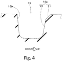
- FIG. 4 shows a cross-sectional view of the shoulder lateral groove 15 taken along a line A-A.
- a groove wall 15a at the toe side in the rotational direction R of the shoulder lateral groove 15 includes a main body portion 20 that extends in the tire radial direction from a bottom portion, and a chamfered portion 21 that extends at a larger angle relative to the tire radial direction than the main body portion 20.
- a groove wall 15b at the heel side in the rotational direction R of the shoulder lateral groove 15 extends from the bottom portion to the groove edge at a constant angle relative to the tire radial direction.
- the groove edge connected to the groove wall 15b at the heel side cuts a water film during running on a wet road surface and thus can effectively prevent a hydroplaning phenomenon.
- each shoulder block 16 has a shoulder short groove 22 and a plurality of shoulder sipes 23.
- the shoulder short groove 22 extends from the tread edge Te and terminates within the shoulder block 16.
- the shoulder short groove 22 is inclined in the same direction as the shoulder lateral groove 15.
- the shoulder short groove 22 of the present embodiment is provided at the same angle relative to the tire axial direction as the shoulder lateral groove 15.
- the length L3 in the tire axial direction of the shoulder short groove 22 is, for example, 0.40 to 0.60 times the maximum width W3 in the tire axial direction of the shoulder land portion 7.
- Such a shoulder short groove 22 serves to enhance steering stability and wet performance in a well-balanced manner.
- the depth of the shoulder short groove 22 is preferably 0.70 to 0.90 times the depth of the shoulder main groove 5.
- Each shoulder sipe 23 extends, for example, so as to be inclined in the same direction relative to the tire axial direction as the shoulder lateral groove 15.
- the angle of the shoulder sipe 23 relative to the tire axial direction is, for example, not greater than 45° and preferably 5 to 15°.
- the shoulder sipes 23 of the present embodiment include sipes that extend from the tread edge Te or the shoulder main groove 5 and that terminate within the shoulder land portion 7.
- the terminal ends of two shoulder sipes 23 are adjacent to each other with a gap of 1.0 to 3.0 mm therebetween.
- one shoulder sipe 23 extends from the shoulder short groove 22 to the shoulder main groove 5. Such a shoulder sipe 23 can inhibit a hydroplaning phenomenon while maintaining steering stability during cornering.
- each shoulder sipe 23 is, for example, 0.5 to 1.0 mm.
- the depth of each shoulder sipe 23 is, for example, 0.05 to 0.15 times the depth of the shoulder main groove 5.
- the total area S2 of the tread surface of the middle land portion 8 is preferably 11.0% to 14.0% of the total area St of the virtual tread surface.
- the total area S2 of the tread surface of the middle land portion 8 is, for example, 0.60 to 0.97 times and more preferably 0.75 to 0.85 times the total area S1 of the tread surface of the shoulder land portion 7. Accordingly, the steering response during cornering becomes linear, so that excellent steering stability is achieved.
- Each middle lateral groove 12 is inclined, for example, to the toe side in the rotational direction R from the shoulder main groove 5 toward the crown main groove 6 side.
- the angle of the middle lateral groove 12 relative to the tire circumferential direction is, for example, 10 to 40°.
- Such a middle lateral groove 12 guides water within this groove to the tread edge Te side with rotation of the tire during running on a wet road surface, and, further, effectively inhibits a hydroplaning phenomenon.
- the middle lateral groove 12 includes, for example, a first portion 26 that extends from the shoulder main groove 5, and a second portion 27 that is connected to the first portion 26 and that extends at a smaller angle relative to the tire circumferential direction than the first portion 26.
- the angle of the first portion 26 relative to the tire circumferential direction is, for example, 20 to 40°.
- the angle of the second portion 27 relative to the tire circumferential direction is, for example, 5 to 20°.
- the second portion 27 is inclined at a larger angle relative to the tire circumferential direction than the gently inclined portion 5a of the shoulder main groove 5.
- Such a middle lateral groove 12 maintains the stiffness in the tire axial direction of the middle land portion 8, and improves steering stability during cornering.
- the distance L4 in the tire axial direction from the end at the crown main groove 6 side of a groove center line of the middle lateral groove 12 to the groove edge of the crown main groove 6 is, for example, preferably 0.10 to 0.20 times the maximum width W4 in the tire axial direction of the middle land portion 8. Accordingly, the width of the rib region 13 is sufficiently ensured, so that excellent steering stability is exhibited.
- a transverse cross-section of the middle lateral groove 12 is, for example, preferably substantially the same as the shape of a transverse cross-section of the shoulder lateral groove 15 described above. That is, in a transverse cross-section of the middle lateral groove 12, a groove wall 12a at the toe side in the rotational direction R of the middle lateral groove 12 includes a main body portion 28 that extends in the tire radial direction from a bottom portion, and a chamfered portion 29 that extends at a larger angle relative to the tire radial direction than the main body portion 28.
- a groove wall 12b at the heel side in the rotational direction R of the middle lateral groove 12 extends from the bottom portion to the groove edge at a constant angle relative to the tire radial direction.
- Such a middle lateral groove 12 can effectively inhibit a hydroplaning phenomenon.
- the middle lateral groove 12 of the present embodiment is provided, for example, at a position at which the middle lateral groove 12 is smoothly connected to the shoulder lateral groove 15 via the shoulder main groove 5. Specifically, a region obtained by extending the first portion 26 of the middle lateral groove 12 in the longitudinal direction thereof overlaps the widening portion 18 of the shoulder lateral groove 15. Accordingly, the shoulder lateral groove 15 and the middle lateral groove 12 cooperate to exhibit high drainage performance.
- the rib region 13 and the block region 14 of the middle land portion 8 have a plurality of middle sipes 30.
- Each middle sipe 30 is, for example, inclined in the same direction relative to the tire axial direction as the middle lateral groove 12.
- the angle of the middle sipe 30 relative to the tire axial direction is, for example, not greater than 45° and preferably 5 to 15°.
- Each middle sipe 30 extends from the main groove 3 or the middle lateral groove 12 and terminates within the middle land portion 8.
- the terminal ends of two middle sipes 30 are adjacent to each other with a gap of 1.0 to 3.0 mm therebetween.
- Such arrangement of the middle sipes 30 can inhibit a hydroplaning phenomenon while maintaining steering stability during cornering.
- each middle sipe 30 is, for example, 0.5 to 1.0 mm.
- the depth of each middle sipe 30 is, for example, 0.05 to 0.15 times the depth of the shoulder main groove 5.
- FIG. 5 shows an enlarged view of the crown land portion 9.
- the crown land portion 9 is a rib continuously extending in the tire circumferential direction.
- Such a crown land portion 9 has high stiffness and serves to exhibit excellent steering stability.
- the width W5 in the tire axial direction of the crown land portion 9 is, for example, preferably 0.05 to 0.15 times the tread width TW.
- the total area S3 of the tread surface of the crown land portion 9 is preferably 4.0% to 10.0% of the total area St of the virtual tread surface.
- the total area S3 of the tread surface of the crown land portion 9 is preferably 0.60 to 0.80 times of the total area S2 of the tread surface of the middle land portion 8.
- the crown land portion 9 has a plurality of crown sipes 31.
- Each crown sipe 31, for example, extends along the tire axial direction from the crown main groove 6 and terminates within the crown land portion 9.
- the terminal ends of two crown sipes 31 are adjacent to each other with a gap of 1.0 to 3.0 mm therebetween.
- each crown sipe 31 is, for example, 0.5 to 1.0 mm.
- the depth of each crown sipe 31 is, for example, preferably larger than the depth of the middle sipe 30 and the depth of the shoulder sipe 23. Specifically, the depth of each crown sipe 31 is preferably 0.40 to 0.60 times the depth of the shoulder main groove 5. Accordingly, steering stability and wet performance can be enhanced in a well-balanced manner during straight running and at the beginning of cornering.
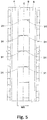
- FIG. 6 shows a development of a tread portion 2 of a tire 1 according to the second embodiment of the present invention.
- the tread portion 2 is divided into six land portions 4 by five main grooves 3 continuously extending in the tire circumferential direction.
- the five main grooves 3 include two shoulder main grooves 5 and three crown main grooves 6.
- the three crown main grooves 6 are provided between the two shoulder main grooves 5.
- the six land portions 4 include two shoulder land portions 7, two middle land portions 8, and two crown land portions 9.
- the three crown main grooves 6 include two first crown main grooves 6A provided with the tire equator C therebetween, and a second crown main groove 6B provided between the two first crown main grooves 6A.
- the second crown main groove 6B of the present embodiment is, for example, located on the tire equator C.
- the structure of the crown main groove 6 shown in FIG. 1 can be applied to each first crown main groove 6A.
- the groove width and the groove depth of the second crown main groove 6B are, for example, smaller than the groove width and the groove depth of the first crown main groove 6A.
- the groove width of the second crown main groove 6B is, for example, 30% to 50% of the groove width of the first crown main groove 6A.
- the groove depth of the second crown main groove 6B is, for example, 30% to 50% of the groove depth of the first crown main groove 6A.
- Each of the two crown land portions 9 is demarcated between the first crown main groove 6A and the second crown main groove 6B.
- the two crown land portions 9 are preferably formed in shapes that are in line symmetry with each other with respect to the tire equator C.
- the total area S4 of the tread surface of one crown land portion 9 is not less than 3.0% and preferably 3.0% to 5.0% of the total area St of the virtual tread surface.
- Such a crown land portion 9 serves to enhance steering stability and wet performance in a well-balanced manner.
- a value obtained by doubling the total area S4 of the tread surface of one crown land portion 9 is the total area S3 of the tread surface of the entire crown land portion 9.
- Tires having the basic pattern in FIG. 1 were produced as test tires on the basis of specifications in Table 1. Regarding the size of each tire, the tread width is 310 mm, the outer diameter is 710 mm, and the rim diameter is 18 inches.
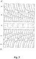
- a tire, in which the total area S2 of the tread surface of each middle land portion a is larger than the total area S1 of the tread surface of each shoulder land portion b as shown in FIG. 7 was produced as a test tire.
- the tire of the comparative example has the same structure as that of each of the tires of the examples, except for the above structure.
- Each test tire was tested for steering stability and wet performance.
- the common specifications and the test methods for the respective test tires are as follows. Mount rim: 18 ⁇ 13.0J Tire internal pressure: 180 kPa Test vehicle: a rear-wheel-drive car having an engine displacement of 3400 cc Tire mounted position: all wheels
- the above test vehicle was driven on an asphalt road surface having a radius of 100 m and provided with a puddle having a depth of 5 mm and a length of 20 m, and the lateral acceleration (lateral G) of the front wheels was measured.
- the results are averages of the lateral G at speeds of 50 to 80 km/h, and are indicated as indexes with the value of the comparative example being regarded as 100. A higher value indicates that the wet performance is better.
- FIG. 1 FIG. 1 FIG. 6 FIG. 6 Total area S1 of tread surface of shoulder land portion / total area St of virtual tread surface (%) 17.0 15.5 13.5 15.5 15.5 Total area S2 of tread surface of middle land portion / total area St of virtual tread surface (%) 14.0 12.5 11.5 12.5 12.5 Total area S3 of tread surface of crown land portion / total area St of virtual tread surface (%) 4.0 5.0 10.0 7.0 5.0 Steering stability (score) 104 102 106 105 98 Wet performance (index) 104 104 102 104 105 105
Landscapes
- Engineering & Computer Science (AREA)
- Mechanical Engineering (AREA)
- Tires In General (AREA)
Applications Claiming Priority (2)
| Application Number | Priority Date | Filing Date | Title |
|---|---|---|---|
| JP2019036509 | 2019-02-28 | ||
| JP2019225756A JP7409062B2 (ja) | 2019-02-28 | 2019-12-13 | タイヤ |
Publications (2)
| Publication Number | Publication Date |
|---|---|
| EP3702176A1 true EP3702176A1 (fr) | 2020-09-02 |
| EP3702176B1 EP3702176B1 (fr) | 2021-04-07 |
Family
ID=69740275
Family Applications (1)
| Application Number | Title | Priority Date | Filing Date |
|---|---|---|---|
| EP20159611.1A Active EP3702176B1 (fr) | 2019-02-28 | 2020-02-26 | Pneumatique |
Country Status (2)
| Country | Link |
|---|---|
| EP (1) | EP3702176B1 (fr) |
| CN (1) | CN111619290B (fr) |
Cited By (1)
| Publication number | Priority date | Publication date | Assignee | Title |
|---|---|---|---|---|
| WO2022100798A1 (fr) * | 2020-11-16 | 2022-05-19 | Continental Reifen Deutschland Gmbh | Bandage pneumatique de véhicule |
Citations (9)
| Publication number | Priority date | Publication date | Assignee | Title |
|---|---|---|---|---|
| JPH0569706A (ja) * | 1991-09-10 | 1993-03-23 | Ohtsu Tire & Rubber Co Ltd :The | 空気入りタイヤ |
| EP1372988A1 (fr) * | 2001-03-30 | 2004-01-02 | PIRELLI PNEUMATICI S.p.A. | Sculpture de bande de roulement pour un pneumatique automobile |
| JP2004017863A (ja) * | 2002-06-18 | 2004-01-22 | Sumitomo Rubber Ind Ltd | 空気入りタイヤ |
| EP1614549A1 (fr) * | 2003-02-28 | 2006-01-11 | Sumitomo Rubber Industries, Ltd. | Pneumatique |
| JP2007055333A (ja) * | 2005-08-23 | 2007-03-08 | Bridgestone Corp | 空気入りタイヤ |
| JP2012140091A (ja) * | 2010-12-29 | 2012-07-26 | Sumitomo Rubber Ind Ltd | 空気入りタイヤ |
| JP2015171841A (ja) * | 2014-03-11 | 2015-10-01 | 住友ゴム工業株式会社 | 空気入りタイヤ |
| JP2015171840A (ja) * | 2014-03-11 | 2015-10-01 | 住友ゴム工業株式会社 | 空気入りタイヤ |
| JP2015171872A (ja) | 2014-03-12 | 2015-10-01 | 住友ゴム工業株式会社 | 空気入りタイヤ |
Family Cites Families (15)
| Publication number | Priority date | Publication date | Assignee | Title |
|---|---|---|---|---|
| JP4081333B2 (ja) * | 2001-09-17 | 2008-04-23 | 株式会社ブリヂストン | 空気入りタイヤ |
| JP5321093B2 (ja) * | 2009-01-26 | 2013-10-23 | 横浜ゴム株式会社 | 空気入りタイヤ |
| EP2432652B1 (fr) * | 2009-05-19 | 2018-04-04 | Pirelli Tyre S.p.A. | Pneumatique pour un vehicule automobile |
| JP5695476B2 (ja) * | 2011-04-12 | 2015-04-08 | 住友ゴム工業株式会社 | 空気入りタイヤ |
| JP5337201B2 (ja) * | 2011-06-20 | 2013-11-06 | 住友ゴム工業株式会社 | 空気入りタイヤ |
| JP5870047B2 (ja) * | 2013-01-08 | 2016-02-24 | 住友ゴム工業株式会社 | 空気入りタイヤ |
| JP5890796B2 (ja) * | 2013-04-11 | 2016-03-22 | 住友ゴム工業株式会社 | 空気入りタイヤ |
| WO2015079858A1 (fr) * | 2013-11-27 | 2015-06-04 | 横浜ゴム株式会社 | Pneumatique |
| KR101824569B1 (ko) * | 2014-05-22 | 2018-02-02 | 요코하마 고무 가부시키가이샤 | 공기입 타이어 |
| JP6104215B2 (ja) * | 2014-09-24 | 2017-03-29 | 住友ゴム工業株式会社 | 空気入りタイヤ |
| JP6582726B2 (ja) * | 2015-08-20 | 2019-10-02 | 住友ゴム工業株式会社 | タイヤ |
| JP6711169B2 (ja) * | 2016-06-24 | 2020-06-17 | 住友ゴム工業株式会社 | タイヤ |
| JP6848359B2 (ja) * | 2016-11-08 | 2021-03-24 | 住友ゴム工業株式会社 | タイヤ |
| JP6777531B2 (ja) * | 2016-12-27 | 2020-10-28 | Toyo Tire株式会社 | 空気入りタイヤ |
| JP6900758B2 (ja) * | 2017-04-14 | 2021-07-07 | 住友ゴム工業株式会社 | タイヤ |
-
2020
- 2020-02-25 CN CN202010116075.1A patent/CN111619290B/zh active Active
- 2020-02-26 EP EP20159611.1A patent/EP3702176B1/fr active Active
Patent Citations (9)
| Publication number | Priority date | Publication date | Assignee | Title |
|---|---|---|---|---|
| JPH0569706A (ja) * | 1991-09-10 | 1993-03-23 | Ohtsu Tire & Rubber Co Ltd :The | 空気入りタイヤ |
| EP1372988A1 (fr) * | 2001-03-30 | 2004-01-02 | PIRELLI PNEUMATICI S.p.A. | Sculpture de bande de roulement pour un pneumatique automobile |
| JP2004017863A (ja) * | 2002-06-18 | 2004-01-22 | Sumitomo Rubber Ind Ltd | 空気入りタイヤ |
| EP1614549A1 (fr) * | 2003-02-28 | 2006-01-11 | Sumitomo Rubber Industries, Ltd. | Pneumatique |
| JP2007055333A (ja) * | 2005-08-23 | 2007-03-08 | Bridgestone Corp | 空気入りタイヤ |
| JP2012140091A (ja) * | 2010-12-29 | 2012-07-26 | Sumitomo Rubber Ind Ltd | 空気入りタイヤ |
| JP2015171841A (ja) * | 2014-03-11 | 2015-10-01 | 住友ゴム工業株式会社 | 空気入りタイヤ |
| JP2015171840A (ja) * | 2014-03-11 | 2015-10-01 | 住友ゴム工業株式会社 | 空気入りタイヤ |
| JP2015171872A (ja) | 2014-03-12 | 2015-10-01 | 住友ゴム工業株式会社 | 空気入りタイヤ |
Cited By (1)
| Publication number | Priority date | Publication date | Assignee | Title |
|---|---|---|---|---|
| WO2022100798A1 (fr) * | 2020-11-16 | 2022-05-19 | Continental Reifen Deutschland Gmbh | Bandage pneumatique de véhicule |
Also Published As
| Publication number | Publication date |
|---|---|
| CN111619290B (zh) | 2024-03-22 |
| EP3702176B1 (fr) | 2021-04-07 |
| CN111619290A (zh) | 2020-09-04 |
Similar Documents
| Publication | Publication Date | Title |
|---|---|---|
| EP3153334B1 (fr) | Pneu | |
| US9150056B2 (en) | Pneumatic tire | |
| EP3260308B1 (fr) | Pneumatique | |
| EP3178668B1 (fr) | Pneumatique | |
| EP2818334B1 (fr) | Pneumatique | |
| EP3263367B1 (fr) | Pneumatique | |
| EP2752309B1 (fr) | Pneu | |
| EP3248810B1 (fr) | Pneumatique | |
| EP3098090B1 (fr) | Pneu d'hiver | |
| EP3375633B1 (fr) | Pneumatique | |
| EP3388255B1 (fr) | Pneumatique | |
| EP3456552B1 (fr) | Pneumatique | |
| EP3960504B1 (fr) | Pneumatique | |
| EP3199378B1 (fr) | Pneumatique | |
| JP7409062B2 (ja) | タイヤ | |
| EP3689642B1 (fr) | Pneumatique | |
| EP3747672B1 (fr) | Bande de roulement de pneumatique | |
| US11560019B2 (en) | Tire | |
| EP3702176B1 (fr) | Pneumatique | |
| EP4105040B1 (fr) | Pneumatique | |
| EP3970996B1 (fr) | Pneumatique | |
| EP4205997B1 (fr) | Pneumatique | |
| EP4335664A1 (fr) | Pneumatique | |
| EP3835087B1 (fr) | Pneumatique | |
| JP2025080625A (ja) | タイヤ |
Legal Events
| Date | Code | Title | Description |
|---|---|---|---|
| PUAI | Public reference made under article 153(3) epc to a published international application that has entered the european phase |
Free format text: ORIGINAL CODE: 0009012 |
|
| STAA | Information on the status of an ep patent application or granted ep patent |
Free format text: STATUS: THE APPLICATION HAS BEEN PUBLISHED |
|
| AK | Designated contracting states |
Kind code of ref document: A1 Designated state(s): AL AT BE BG CH CY CZ DE DK EE ES FI FR GB GR HR HU IE IS IT LI LT LU LV MC MK MT NL NO PL PT RO RS SE SI SK SM TR |
|
| AX | Request for extension of the european patent |
Extension state: BA ME |
|
| STAA | Information on the status of an ep patent application or granted ep patent |
Free format text: STATUS: REQUEST FOR EXAMINATION WAS MADE |
|
| 17P | Request for examination filed |
Effective date: 20201109 |
|
| RBV | Designated contracting states (corrected) |
Designated state(s): AL AT BE BG CH CY CZ DE DK EE ES FI FR GB GR HR HU IE IS IT LI LT LU LV MC MK MT NL NO PL PT RO RS SE SI SK SM TR |
|
| RIC1 | Information provided on ipc code assigned before grant |
Ipc: B60C 11/12 20060101ALI20201120BHEP Ipc: B60C 11/03 20060101AFI20201120BHEP |
|
| GRAP | Despatch of communication of intention to grant a patent |
Free format text: ORIGINAL CODE: EPIDOSNIGR1 |
|
| STAA | Information on the status of an ep patent application or granted ep patent |
Free format text: STATUS: GRANT OF PATENT IS INTENDED |
|
| INTG | Intention to grant announced |
Effective date: 20210114 |
|
| GRAS | Grant fee paid |
Free format text: ORIGINAL CODE: EPIDOSNIGR3 |
|
| GRAA | (expected) grant |
Free format text: ORIGINAL CODE: 0009210 |
|
| STAA | Information on the status of an ep patent application or granted ep patent |
Free format text: STATUS: THE PATENT HAS BEEN GRANTED |
|
| AK | Designated contracting states |
Kind code of ref document: B1 Designated state(s): AL AT BE BG CH CY CZ DE DK EE ES FI FR GB GR HR HU IE IS IT LI LT LU LV MC MK MT NL NO PL PT RO RS SE SI SK SM TR |
|
| REG | Reference to a national code |
Ref country code: GB Ref legal event code: FG4D |
|
| REG | Reference to a national code |
Ref country code: AT Ref legal event code: REF Ref document number: 1379204 Country of ref document: AT Kind code of ref document: T Effective date: 20210415 Ref country code: CH Ref legal event code: EP |
|
| REG | Reference to a national code |
Ref country code: DE Ref legal event code: R096 Ref document number: 602020000048 Country of ref document: DE |
|
| REG | Reference to a national code |
Ref country code: IE Ref legal event code: FG4D |
|
| REG | Reference to a national code |
Ref country code: LT Ref legal event code: MG9D |
|
| REG | Reference to a national code |
Ref country code: NL Ref legal event code: MP Effective date: 20210407 Ref country code: AT Ref legal event code: MK05 Ref document number: 1379204 Country of ref document: AT Kind code of ref document: T Effective date: 20210407 |
|
| PG25 | Lapsed in a contracting state [announced via postgrant information from national office to epo] |
Ref country code: NL Free format text: LAPSE BECAUSE OF FAILURE TO SUBMIT A TRANSLATION OF THE DESCRIPTION OR TO PAY THE FEE WITHIN THE PRESCRIBED TIME-LIMIT Effective date: 20210407 Ref country code: AT Free format text: LAPSE BECAUSE OF FAILURE TO SUBMIT A TRANSLATION OF THE DESCRIPTION OR TO PAY THE FEE WITHIN THE PRESCRIBED TIME-LIMIT Effective date: 20210407 Ref country code: BG Free format text: LAPSE BECAUSE OF FAILURE TO SUBMIT A TRANSLATION OF THE DESCRIPTION OR TO PAY THE FEE WITHIN THE PRESCRIBED TIME-LIMIT Effective date: 20210707 Ref country code: FI Free format text: LAPSE BECAUSE OF FAILURE TO SUBMIT A TRANSLATION OF THE DESCRIPTION OR TO PAY THE FEE WITHIN THE PRESCRIBED TIME-LIMIT Effective date: 20210407 Ref country code: HR Free format text: LAPSE BECAUSE OF FAILURE TO SUBMIT A TRANSLATION OF THE DESCRIPTION OR TO PAY THE FEE WITHIN THE PRESCRIBED TIME-LIMIT Effective date: 20210407 Ref country code: LT Free format text: LAPSE BECAUSE OF FAILURE TO SUBMIT A TRANSLATION OF THE DESCRIPTION OR TO PAY THE FEE WITHIN THE PRESCRIBED TIME-LIMIT Effective date: 20210407 |
|
| PG25 | Lapsed in a contracting state [announced via postgrant information from national office to epo] |
Ref country code: PT Free format text: LAPSE BECAUSE OF FAILURE TO SUBMIT A TRANSLATION OF THE DESCRIPTION OR TO PAY THE FEE WITHIN THE PRESCRIBED TIME-LIMIT Effective date: 20210809 Ref country code: RS Free format text: LAPSE BECAUSE OF FAILURE TO SUBMIT A TRANSLATION OF THE DESCRIPTION OR TO PAY THE FEE WITHIN THE PRESCRIBED TIME-LIMIT Effective date: 20210407 Ref country code: SE Free format text: LAPSE BECAUSE OF FAILURE TO SUBMIT A TRANSLATION OF THE DESCRIPTION OR TO PAY THE FEE WITHIN THE PRESCRIBED TIME-LIMIT Effective date: 20210407 Ref country code: LV Free format text: LAPSE BECAUSE OF FAILURE TO SUBMIT A TRANSLATION OF THE DESCRIPTION OR TO PAY THE FEE WITHIN THE PRESCRIBED TIME-LIMIT Effective date: 20210407 Ref country code: NO Free format text: LAPSE BECAUSE OF FAILURE TO SUBMIT A TRANSLATION OF THE DESCRIPTION OR TO PAY THE FEE WITHIN THE PRESCRIBED TIME-LIMIT Effective date: 20210707 Ref country code: PL Free format text: LAPSE BECAUSE OF FAILURE TO SUBMIT A TRANSLATION OF THE DESCRIPTION OR TO PAY THE FEE WITHIN THE PRESCRIBED TIME-LIMIT Effective date: 20210407 Ref country code: IS Free format text: LAPSE BECAUSE OF FAILURE TO SUBMIT A TRANSLATION OF THE DESCRIPTION OR TO PAY THE FEE WITHIN THE PRESCRIBED TIME-LIMIT Effective date: 20210807 Ref country code: GR Free format text: LAPSE BECAUSE OF FAILURE TO SUBMIT A TRANSLATION OF THE DESCRIPTION OR TO PAY THE FEE WITHIN THE PRESCRIBED TIME-LIMIT Effective date: 20210708 |
|
| REG | Reference to a national code |
Ref country code: DE Ref legal event code: R097 Ref document number: 602020000048 Country of ref document: DE |
|
| PG25 | Lapsed in a contracting state [announced via postgrant information from national office to epo] |
Ref country code: DK Free format text: LAPSE BECAUSE OF FAILURE TO SUBMIT A TRANSLATION OF THE DESCRIPTION OR TO PAY THE FEE WITHIN THE PRESCRIBED TIME-LIMIT Effective date: 20210407 Ref country code: CZ Free format text: LAPSE BECAUSE OF FAILURE TO SUBMIT A TRANSLATION OF THE DESCRIPTION OR TO PAY THE FEE WITHIN THE PRESCRIBED TIME-LIMIT Effective date: 20210407 Ref country code: SM Free format text: LAPSE BECAUSE OF FAILURE TO SUBMIT A TRANSLATION OF THE DESCRIPTION OR TO PAY THE FEE WITHIN THE PRESCRIBED TIME-LIMIT Effective date: 20210407 Ref country code: RO Free format text: LAPSE BECAUSE OF FAILURE TO SUBMIT A TRANSLATION OF THE DESCRIPTION OR TO PAY THE FEE WITHIN THE PRESCRIBED TIME-LIMIT Effective date: 20210407 Ref country code: ES Free format text: LAPSE BECAUSE OF FAILURE TO SUBMIT A TRANSLATION OF THE DESCRIPTION OR TO PAY THE FEE WITHIN THE PRESCRIBED TIME-LIMIT Effective date: 20210407 Ref country code: EE Free format text: LAPSE BECAUSE OF FAILURE TO SUBMIT A TRANSLATION OF THE DESCRIPTION OR TO PAY THE FEE WITHIN THE PRESCRIBED TIME-LIMIT Effective date: 20210407 Ref country code: SK Free format text: LAPSE BECAUSE OF FAILURE TO SUBMIT A TRANSLATION OF THE DESCRIPTION OR TO PAY THE FEE WITHIN THE PRESCRIBED TIME-LIMIT Effective date: 20210407 |
|
| PLBE | No opposition filed within time limit |
Free format text: ORIGINAL CODE: 0009261 |
|
| STAA | Information on the status of an ep patent application or granted ep patent |
Free format text: STATUS: NO OPPOSITION FILED WITHIN TIME LIMIT |
|
| 26N | No opposition filed |
Effective date: 20220110 |
|
| PG25 | Lapsed in a contracting state [announced via postgrant information from national office to epo] |
Ref country code: IS Free format text: LAPSE BECAUSE OF FAILURE TO SUBMIT A TRANSLATION OF THE DESCRIPTION OR TO PAY THE FEE WITHIN THE PRESCRIBED TIME-LIMIT Effective date: 20210807 Ref country code: AL Free format text: LAPSE BECAUSE OF FAILURE TO SUBMIT A TRANSLATION OF THE DESCRIPTION OR TO PAY THE FEE WITHIN THE PRESCRIBED TIME-LIMIT Effective date: 20210407 |
|
| PG25 | Lapsed in a contracting state [announced via postgrant information from national office to epo] |
Ref country code: IT Free format text: LAPSE BECAUSE OF FAILURE TO SUBMIT A TRANSLATION OF THE DESCRIPTION OR TO PAY THE FEE WITHIN THE PRESCRIBED TIME-LIMIT Effective date: 20210407 |
|
| PG25 | Lapsed in a contracting state [announced via postgrant information from national office to epo] |
Ref country code: MC Free format text: LAPSE BECAUSE OF FAILURE TO SUBMIT A TRANSLATION OF THE DESCRIPTION OR TO PAY THE FEE WITHIN THE PRESCRIBED TIME-LIMIT Effective date: 20210407 |
|
| REG | Reference to a national code |
Ref country code: BE Ref legal event code: MM Effective date: 20220228 |
|
| PG25 | Lapsed in a contracting state [announced via postgrant information from national office to epo] |
Ref country code: LU Free format text: LAPSE BECAUSE OF NON-PAYMENT OF DUE FEES Effective date: 20220226 |
|
| PG25 | Lapsed in a contracting state [announced via postgrant information from national office to epo] |
Ref country code: IE Free format text: LAPSE BECAUSE OF NON-PAYMENT OF DUE FEES Effective date: 20220226 |
|
| PG25 | Lapsed in a contracting state [announced via postgrant information from national office to epo] |
Ref country code: BE Free format text: LAPSE BECAUSE OF NON-PAYMENT OF DUE FEES Effective date: 20220228 |
|
| P01 | Opt-out of the competence of the unified patent court (upc) registered |
Effective date: 20230510 |
|
| REG | Reference to a national code |
Ref country code: CH Ref legal event code: PL |
|
| PG25 | Lapsed in a contracting state [announced via postgrant information from national office to epo] |
Ref country code: LI Free format text: LAPSE BECAUSE OF NON-PAYMENT OF DUE FEES Effective date: 20230228 Ref country code: CH Free format text: LAPSE BECAUSE OF NON-PAYMENT OF DUE FEES Effective date: 20230228 |
|
| PG25 | Lapsed in a contracting state [announced via postgrant information from national office to epo] |
Ref country code: MK Free format text: LAPSE BECAUSE OF FAILURE TO SUBMIT A TRANSLATION OF THE DESCRIPTION OR TO PAY THE FEE WITHIN THE PRESCRIBED TIME-LIMIT Effective date: 20210407 Ref country code: CY Free format text: LAPSE BECAUSE OF FAILURE TO SUBMIT A TRANSLATION OF THE DESCRIPTION OR TO PAY THE FEE WITHIN THE PRESCRIBED TIME-LIMIT Effective date: 20210407 |
|
| PG25 | Lapsed in a contracting state [announced via postgrant information from national office to epo] |
Ref country code: HU Free format text: LAPSE BECAUSE OF FAILURE TO SUBMIT A TRANSLATION OF THE DESCRIPTION OR TO PAY THE FEE WITHIN THE PRESCRIBED TIME-LIMIT; INVALID AB INITIO Effective date: 20200226 |
|
| PG25 | Lapsed in a contracting state [announced via postgrant information from national office to epo] |
Ref country code: MT Free format text: LAPSE BECAUSE OF FAILURE TO SUBMIT A TRANSLATION OF THE DESCRIPTION OR TO PAY THE FEE WITHIN THE PRESCRIBED TIME-LIMIT Effective date: 20210407 |
|
| GBPC | Gb: european patent ceased through non-payment of renewal fee |
Effective date: 20240226 |
|
| PG25 | Lapsed in a contracting state [announced via postgrant information from national office to epo] |
Ref country code: GB Free format text: LAPSE BECAUSE OF NON-PAYMENT OF DUE FEES Effective date: 20240226 |
|
| PG25 | Lapsed in a contracting state [announced via postgrant information from national office to epo] |
Ref country code: GB Free format text: LAPSE BECAUSE OF NON-PAYMENT OF DUE FEES Effective date: 20240226 |
|
| PG25 | Lapsed in a contracting state [announced via postgrant information from national office to epo] |
Ref country code: TR Free format text: LAPSE BECAUSE OF FAILURE TO SUBMIT A TRANSLATION OF THE DESCRIPTION OR TO PAY THE FEE WITHIN THE PRESCRIBED TIME-LIMIT Effective date: 20210407 |
|
| PGFP | Annual fee paid to national office [announced via postgrant information from national office to epo] |
Ref country code: FR Payment date: 20251231 Year of fee payment: 7 |
|
| PGFP | Annual fee paid to national office [announced via postgrant information from national office to epo] |
Ref country code: DE Payment date: 20260102 Year of fee payment: 7 |