EP3702178A1 - Capteur de pression de pneu - Google Patents
Capteur de pression de pneu Download PDFInfo
- Publication number
- EP3702178A1 EP3702178A1 EP19874767.7A EP19874767A EP3702178A1 EP 3702178 A1 EP3702178 A1 EP 3702178A1 EP 19874767 A EP19874767 A EP 19874767A EP 3702178 A1 EP3702178 A1 EP 3702178A1
- Authority
- EP
- European Patent Office
- Prior art keywords
- tire pressure
- pressure sensor
- locking
- rod
- groove
- Prior art date
- Legal status (The legal status is an assumption and is not a legal conclusion. Google has not performed a legal analysis and makes no representation as to the accuracy of the status listed.)
- Withdrawn
Links
- 238000003825 pressing Methods 0.000 claims description 58
- 230000000712 assembly Effects 0.000 claims description 18
- 238000000429 assembly Methods 0.000 claims description 18
- 239000002184 metal Substances 0.000 claims description 11
- 229910052751 metal Inorganic materials 0.000 claims description 11
- 230000006835 compression Effects 0.000 claims description 6
- 238000007906 compression Methods 0.000 claims description 6
- 239000000463 material Substances 0.000 claims description 6
- 238000004891 communication Methods 0.000 claims description 5
- 239000007769 metal material Substances 0.000 claims description 4
- 238000003466 welding Methods 0.000 claims description 4
- 230000007423 decrease Effects 0.000 claims description 2
- 238000001514 detection method Methods 0.000 abstract description 9
- 238000005516 engineering process Methods 0.000 abstract description 2
- 238000000034 method Methods 0.000 description 5
- 238000012544 monitoring process Methods 0.000 description 3
- RYGMFSIKBFXOCR-UHFFFAOYSA-N Copper Chemical compound [Cu] RYGMFSIKBFXOCR-UHFFFAOYSA-N 0.000 description 2
- 229910000881 Cu alloy Inorganic materials 0.000 description 2
- 229910052802 copper Inorganic materials 0.000 description 2
- 239000010949 copper Substances 0.000 description 2
- 238000010586 diagram Methods 0.000 description 2
- 238000004382 potting Methods 0.000 description 2
- 238000005476 soldering Methods 0.000 description 2
- 239000010935 stainless steel Substances 0.000 description 2
- 229910001220 stainless steel Inorganic materials 0.000 description 2
- 230000005540 biological transmission Effects 0.000 description 1
- 239000000084 colloidal system Substances 0.000 description 1
- 230000014509 gene expression Effects 0.000 description 1
- 238000009957 hemming Methods 0.000 description 1
- 238000009434 installation Methods 0.000 description 1
- 238000012986 modification Methods 0.000 description 1
- 230000004048 modification Effects 0.000 description 1
- 239000004033 plastic Substances 0.000 description 1
- 238000007789 sealing Methods 0.000 description 1
- 238000006467 substitution reaction Methods 0.000 description 1
- 230000007704 transition Effects 0.000 description 1
Images





Classifications
-
- B—PERFORMING OPERATIONS; TRANSPORTING
- B60—VEHICLES IN GENERAL
- B60C—VEHICLE TYRES; TYRE INFLATION; TYRE CHANGING; CONNECTING VALVES TO INFLATABLE ELASTIC BODIES IN GENERAL; DEVICES OR ARRANGEMENTS RELATED TO TYRES
- B60C23/00—Devices for measuring, signalling, controlling, or distributing tyre pressure or temperature, specially adapted for mounting on vehicles; Arrangement of tyre inflating devices on vehicles, e.g. of pumps or of tanks; Tyre cooling arrangements
- B60C23/02—Signalling devices actuated by tyre pressure
- B60C23/04—Signalling devices actuated by tyre pressure mounted on the wheel or tyre
-
- B—PERFORMING OPERATIONS; TRANSPORTING
- B60—VEHICLES IN GENERAL
- B60C—VEHICLE TYRES; TYRE INFLATION; TYRE CHANGING; CONNECTING VALVES TO INFLATABLE ELASTIC BODIES IN GENERAL; DEVICES OR ARRANGEMENTS RELATED TO TYRES
- B60C23/00—Devices for measuring, signalling, controlling, or distributing tyre pressure or temperature, specially adapted for mounting on vehicles; Arrangement of tyre inflating devices on vehicles, e.g. of pumps or of tanks; Tyre cooling arrangements
- B60C23/02—Signalling devices actuated by tyre pressure
- B60C23/04—Signalling devices actuated by tyre pressure mounted on the wheel or tyre
- B60C23/0491—Constructional details of means for attaching the control device
- B60C23/0494—Valve stem attachments positioned inside the tyre chamber
-
- B—PERFORMING OPERATIONS; TRANSPORTING
- B60—VEHICLES IN GENERAL
- B60C—VEHICLE TYRES; TYRE INFLATION; TYRE CHANGING; CONNECTING VALVES TO INFLATABLE ELASTIC BODIES IN GENERAL; DEVICES OR ARRANGEMENTS RELATED TO TYRES
- B60C29/00—Arrangements of tyre-inflating valves to tyres or rims; Accessories for tyre-inflating valves, not otherwise provided for
- B60C29/02—Connection to rims
Definitions
- the present application relates to the field of tire pressure detection technologies, and in particular, to a tire pressure sensor.
- a pressure-sensor based tire pressure monitoring system is also referred to as a PSB TPMS.
- the PSB TPMS uses a tire pressure sensor installed on a tire to measure barometric pressure and temperature of the tire, uses a wireless transmitter to send pressure information from a tire interior to a tire pressure detection terminal, and displays barometric pressure data of the tire.
- the system will alert the vehicle owner.
- the owner may set a tire pressure alarm value range and a temperature alarm value according to a vehicle type, car using habits and geographical location.
- a traditional tire pressure sensor includes a sensor and a valve mounted to the sensor.
- the sensor is configured to detect tire information inside the tire
- the valve is configured to inflate and deflate the tire
- the valve and the sensor are generally connected through a threaded fastener.
- the inventor finds that in the current tire pressure sensor, the valve and the sensor are connected through the threaded fastener, the process of installing the valve and the sensor is relatively difficult with long installation time, and needs an extra torque wrench with high costs. Therefore, the prior art needs to be improved.
- an embodiment of the present invention provides a tire pressure sensor.
- a valve assembly and a sensor assembly of the tire pressure sensor are easy to install and do not require additional tools.
- a tire pressure sensor including: a valve assembly including a mounting portion, a rod portion, a rod sleeve and an elastic telescopic structure, the mounting portion being connected to the rod portion, and the rod sleeve being sleeved on the rod portion, the elastic telescopic structure being mounted to the mounting portion, and the elastic telescopic structure elastically extending and retracting on at least one side of the mounting portion; a sensor assembly having two opposite clamping surfaces, at least one of the two clamping surfaces being provided with a locking hole, the mounting portion being located between two of the clamping surfaces, and the elastic telescopic structure being inserted into the locking hole, where there are at least two sets of valve assemblies, any of the at least two sets of the valve assemblies being alternatively connected to the sensor assembly, a rod sleeve of one of the at least two sets of the valve assemblies being made of a metal material, and a rod sleeve of the other of the at least two sets of the valve assemblies being made of a rubber material
- the mounting portion is in contact with two of the clamping surfaces, respectively.
- the valve assembly includes a valve rod, the valve rod including the mounting portion and the rod portion.
- the elastic telescopic structure may extend and retract in a radial direction of the valve rod, and the clamping surface is parallel to an axial direction of the valve rod.
- the sensor assembly has a first surface, the first surface being provided with a groove, and the groove having two of the clamping surfaces; and the mounting portion being inserted into the groove.
- At least one of the clamping surfaces provided with the locking hole is provided with a guide groove, the guide groove being disposed between the locking hole and the first surface along the axial direction.
- a depth of the guide groove gradually decreases.
- the mounting portion is provided with a mounting hole disposed along the radial direction, and the elastic telescopic structure is mounted to the mounting hole.
- the elastic telescopic structure includes a pin and a first elastic member; the pin being sleeved in the mounting hole and retracting into and extending out of the mounting hole in the radial direction; and the first elastic member being configured to provide a first elastic force causing the pin to extend out of the mounting hole.
- the two clamping surfaces are provided with the locking holes
- the mounting holes are provided with two openings on the mounting portion, and there are two pins; each of the pins extending out or retracting into the mounting hole from a corresponding opening of the mounting hole in the radial direction.
- the first elastic member abuts between two of the pins.
- the first elastic member is a first compression spring.
- the elastic telescopic structure further includes a bushing mounted to the mounting hole; the bushing having an inner cavity disposed along the radial direction, and the pin being sleeved in the inner cavity.
- the valve rod further includes a vent portion and a mouth portion, the mounting portion, the vent portion, the rod portion and the mouth portion being sequentially arranged along the axial direction; the valve rod is provided with a first vent hole and a second vent hole that are in communication with each other, an opening of the first vent hole being provided at the mouth portion, and an opening of the second vent hole being provided at the vent portion; and the second vent hole being located outside the groove.
- the second vent hole is disposed along the radial direction.
- the valve assembly further includes a valve cover, the valve cover being connected to the mouth portion through threads.
- the rod sleeve made of metal includes a seal ring, a gasket, and a nut, the seal ring, the gasket, and the nut being sequentially sleeved on the rod portion, the nut and the rod portion being connected through threads, the gasket being clamped between the nut and the seal ring, and the seal ring being clamped between the vent portion and the gasket.
- the tire pressure sensor further includes a metal rod member, the metal rod member being configured to pass through the second vent hole.
- the sensor assembly includes a base and a bracket connected to the base, the base being configured to fit a rim, a transmitting plate being disposed in the base, and the bracket having a first surface.
- the base includes an upper case and a case bottom, the upper case and the bracket being connected, the case bottom being configured to fit a rim, the upper case and the case bottom being connected through laser welding, and the upper case and the case bottom being connected to form a cavity for receiving the transmitting plate.
- the bracket includes a bracket body and a locking structure connected to the bracket body, the bracket body being connected to the base, the bracket body having the first surface, two of the clamping surfaces being provided with a mounting opening, and the locking structure including locking pieces, two of the locking pieces being provided with the locking holes, each of the locking pieces being opposite to a corresponding mounting opening, and each of the locking holes being exposed to a corresponding one mounting opening.
- the bracket body further has a second surface, the second surface being provided with a pressing groove, the pressing groove being located between the second surface and the groove, a bottom of the pressing groove being provided with slots, two of the slots being located on both sides of the groove, and each of the locking pieces being located in a corresponding one of the slots.
- the locking structure further includes a connecting piece, the connecting piece being connected between the two locking pieces, and the connecting piece being in contact with the bottom of the pressing groove.
- the sensor assembly further includes a pressing member and a second elastic member.
- the pressing member includes a moving plate and a pressing plate, the pressing plate being connected between two of the moving plates, each of the moving plates being located in a corresponding one of the slots, and each of the moving plates abutting against a corresponding side that is of the locking piece and that faces away from the groove.
- the pressing plate is opposite to the connecting piece, and when the pressing plate moves toward a direction close to the connecting piece, each of the moving plates moves along a corresponding one of the locking pieces, so that each of the moving plates may extrude a corresponding one of the elastic telescopic structures from the locking hole.
- the second elastic member is configured to provide a second elastic force for moving the pressing plate toward a direction away from the connecting piece.
- the second elastic member is a second compression spring.
- At least one of the two locking pieces is provided with a limiting portion, the limiting portion being located on a side that is of the locking piece and that faces away from the groove.
- a bent plate is provided between the moving plate and the pressing plate, one end of the bent plate being connected to the moving plate, and the other end of the bent plate being connected to the pressing plate.
- the bent plate is U-shaped, so that the two ends of the bent plate are opposite, and the limiting portion is located between the two ends of the bent plate.
- the mounting portion of the valve assembly may be inserted between the two clamping surfaces.
- the elastic telescopic structure may be extended and inserted into the locking hole automatically, so that the valve assembly and the sensor assembly may be installed conveniently, and no additional tools are required.
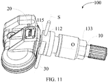
- a tire pressure sensor 100 provided in an embodiment of the present invention includes a sensor assembly 20 and at least two sets of valve assemblies 10 with different specifications.
- the at least two sets of valve assemblies 10 with different specifications may be alternately connected to the sensor assembly 20.
- the at least two sets of valve assemblies 10 with different specifications are disposed, so that a user may mount, according to requirements, valve assemblies that meet the requirements on the sensor assembly 20.
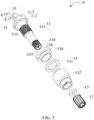
- any of the at least two sets of valve assemblies 10 with different specifications includes a valve rod 11, a valve cover 12, a rod sleeve 13, and an elastic telescopic structure 14.
- the valve cover 12 is mounted to one end of the valve rod 11
- the elastic telescopic structure 14 is mounted to the other end of the valve rod 11
- the rod sleeve 13 is sleeved between two ends of the valve rod 11.
- the valve rod 11 may be made of copper or copper alloy.
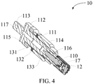
- the valve rod 11 includes a mouth portion 110, a rod portion 111, a vent portion 112, and a mounting portion 113 that are arranged and connected along an axial direction O.
- the valve rod 11 is provided with a first vent hole 114 and a second vent hole 115 that are in communication with each other.
- the first vent hole 114 is disposed along the axial direction O, and an opening of the first vent hole 114 is provided in the mouth portion 110.
- the first vent hole 114 passes through the mouth portion 110 and the rod portion 111 successively, and extends to the vent portion 112, and a valve core 116 is disposed in the first vent hole 114.
- the second vent hole 115 is provided along a radial direction S of the valve rod 11, the second vent hole 115 penetrates through the vent portion 112, the first vent hole 114 is in communication with the second vent hole 115 in the vent portion 112, and the first vent hole 114 and the second vent hole 115 form a T-shaped hole.
- the mouth portion 110 is connected to the valve cover 12 through threads, and the valve cover 12 is configured to close the opening of the first vent hole 114.
- a nut seal ring 17 is provided between the valve cover 12 and the mouth portion 110, the nut seal ring 17 being configured to improve air tightness between the valve cover 12 and the first vent hole 114.
- the rod sleeve 13 is sleeved on the rod portion 111, and a rod sleeve 13 of any of the at least two sets of valve assemblies 10 is different from rod sleeves 13 of the remaining sleeves.
- a rod sleeve 13 of one of the at least two sets of valve assemblies 10 includes a seal ring 130, a gasket 131, and a nut 132. Both the gasket 131 and the nut 132 may be made of copper or copper alloy, and the seal ring 130 may be made of rubber.
- the seal ring 130, the gasket 131 and the nut 132 are sleeved on the rod portion 111 in sequence, the seal ring 130 is clamped between the gasket 131 and the vent portion 112, the gasket 131 is clamped between the seal ring 130 and the nut 132, and the nut 132 is connected to the rod portion 111 through threads.
- a rod sleeve 13 of the other of the at least two sets of valve assemblies 10 may be made of a rubber material.
- the mounting portion 113 is provided with a mounting hole 117 along the radial direction S.
- the mounting hole 117 penetrates through the mounting portion 113, and is configured to mount the elastic telescopic structure 14.
- the elastic telescopic structure 14 may be elastically extended and retracted relative to the mounting portion 113 in the radial direction S.
- the elastic telescopic structure 14 includes a bushing 140, a pin 141, and a first elastic member 142.
- the bushing 140 has a cylindrical shape as a whole.
- the bushing 140 is sleeved in the mounting hole 117.
- the bushing 140 has an inner cavity 1400, the inner cavity 1400 being disposed along the radial direction S.
- the inner cavity 1400 is provided with two opposite openings on the bushing 140, and the inner cavity 1400 is provided with a reduced diameter at both openings thereof.
- each of the pins 141 being sleeved in the inner cavity 1400, and each of the pins 141 may move along the inner cavity 1400, so that each of the pins 141 may extend or retract into a corresponding opening of the inner cavity 1400.
- the first elastic member 142 abuts between two of the pins 141.
- the first elastic member 142 is configured to provide a first elastic force for making the pin 141 extend out of the inner cavity 1400.
- the first elastic member 142 is a first compression spring. According to actual conditions, the first elastic member 142 may also be an elastic piece, an elastic rubber ball, or the like.
- the bushing 140 may be omitted, that is, the pin 141 may be directly sleeved in the mounting hole 117.
- the sensor assembly 20 includes a base 21 and a mounting stand 22 connected to the base 21.
- the base 21 may be made of a plastic material, and a cavity is provided in the base 21.
- Components such as a circuit board 23, a battery 24, and an antenna 25 are mounted in the cavity.
- the circuit board 23 carries various chips, for example, a pressure detection chip, which is provided with an air pressure detection hole 230 and being configured to detect air pressure in the air pressure detection hole 230; and for another example, a wireless transmission chip, which is configured to be wirelessly connected, through the antenna 25, to a tire pressure monitoring terminal located on an automobile dashboard.
- the battery 24 may be a button battery, which is connected to the circuit board 23 by soldering and is configured to supply power to the circuit board 23.
- the antenna 25 may be a radio frequency antenna. The antenna 25 is connected to the circuit board 23 by soldering.
- the antenna 25, the battery 24, and the circuit board 23 form a transmitting plate.
- the base 21 includes a case bottom 210 and an upper case 211.
- the upper case 211 is connected to the case bottom 210 to form the cavity.
- the case bottom 210 may be made of a light-transmissive material, and a surface that is of the case bottom 210 and that faces away from the upper case 211 is configured to fit the rim of the tire.
- the upper case 211 may be made of a dark opaque material.
- a surface that is of the upper case 211 and that faces away from the case bottom 210 is provided with an air hole 2110, the air hole 2110 being aligned with the air pressure detection hole 230 of the air pressure detection chip.
- the air hole 2110 and the air pressure detection hole 230 are sealed using a sealing gasket.
- the upper case 211 and the case bottom 210 are connected through laser welding.
- the upper case 211 and the case bottom 210 are connected through potting.
- the upper case 211 and the case bottom 210 are connected through laser welding, so that the cavity has good gas tightness.
- the upper case 211 and the case bottom 210 have high assembly efficiency, and the damage of the colloid to the human body and the pollution to the environment are reduced.
- the mounting stand 22 is disposed on a side of the upper case 211 away from the case bottom 210.
- a maximum distance between the case bottom 210 and the mounting stand 22 does not exceed a preset distance, so that the sensor assembly 20 can fit the rim of the tire better, to prevent the sensor assembly 20 from suspending when being removed from the tire, so that the sensor assembly 20 is not easily damaged.
- the mounting stand 22 is configured to mount the valve assembly 10.
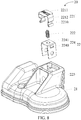
- the mounting stand 22 includes a bracket 220, a pressing member 221, and a second elastic member 222.
- the bracket 220 is configured to mount the valve assembly 10, and includes a bracket body 223 and a locking structure 224 mounted to the bracket body 223.
- the bracket body 223 is connected to the upper case 211.
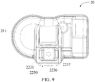
- the bracket body 223 includes a first surface 2230 and a second surface 2231.
- the first surface 2230 is vertical to the case bottom 210, and the second surface 2231 faces away from the case bottom 210.
- a position of the first surface 2230 and a position of the second surface 2231 may be in any state.
- the first surface 2230 and the second surface 2231 are opposite, which is not limited in the present embodiment.
- the first surface 2230 is provided with a groove 2232.
- the groove 2232 is provided along the axial direction O.
- the mounting portion 113 of the valve rod 11 is matched with the groove 2232.
- the mounting portion 113 of the valve rod 11 may be inserted into the groove 2232 along the axial direction O, and the vent portion 112 is located outside the groove 2232, that is, the second vent hole 115 is located outside the groove 2232.
- a groove wall of the groove 2232 has two clamping surfaces 2233 opposite to each other.
- the clamping surface 2233 is parallel to the axial direction O, and is provided with a mounting opening 2234 and a guide groove 2235.
- the guide groove 2235 is located between the first surface 2230 and the mounting opening 2234.
- the guide groove 2235 is separated from the mounting opening 2234.
- the pin 141 may be retracted into an opening of the bushing 140, so that the pin 141 abuts against the clamping surface 2233 and slides into the mounting opening 2234 along the clamping surface 2233.
- the depth of the guide groove 2235 is gradually reduced along the axial direction S from the first surface 2230 toward the mounting opening 2234, so that a smooth transition can be achieved for the pin 141 from abutting against the guide groove 2235 to abutting against the clamping surface 2233.
- the second surface 2231 is provided with a pressing groove 2236.
- the pressing groove 2236 is located between the second surface 2231 and the groove 2232.
- the pressing groove 2236 is generally a flat square groove.
- a bottom of the pressing groove 2236 is provided with two slots 2237, the two slots 2237 being located at two sides of the groove 2232, respectively, and each of the slots 2237 being in communication with a corresponding one of the mounting openings 2234.
- the number of the mounting openings 2234 corresponds to the number of the locking holes 2242, and the guide groove 2235 is provided on the clamping surface 2233 provided with the mounting opening 2234.
- the locking structure 224 is U-shaped as a whole, and may be made of a metal material, for example, a stainless steel piece is manufactured by a hemming process.
- the locking structure 224 includes two locking pieces 2240 and a connecting piece 2241 connected between two of the locking pieces 2240.
- Each of the locking pieces 2240 is located in a corresponding slot 2237, an edge of the locking piece 2240 being provided with ratchets, and the edge of the locking piece 2240 being embedded into the groove wall of the slot 2237.
- the locking piece 2240 is provided with a locking hole 2242 and is opposite to the mounting opening 2234, the locking hole 2242 being exposed to the mounting opening 2234, and the locking piece 2240 being flush with the clamping surface 2233.
- the pin 141 When sliding into the mounting opening 2234, the pin 141 abuts against the locking piece 2240 and moves to the locking hole 2242 along the locking piece 2240.
- the pin 141 is inserted into the locking hole 2242 and abuts against the locking hole 2242, so that the mounting portion 113 of the valve rod 11 cannot be pulled out from the groove 2232 along the axial direction O.
- the locking structure 224, the mounting opening 2234, the pressing groove 2236, and the slot 2237 all may be omitted, and the locking hole 2242 is directly provided on the clamping surface 2233.
- the elastic telescopic structure 14 may be elastically extended and retracted at one side of the mounting portion 113, so that the valve assembly 10 and the sensor assembly 20 can still be assembled.
- the elastic telescopic structure 14 extends and retracts in the radial direction, the clamping surface 2233 is disposed parallel to the axial direction.
- the axial direction O and the radial direction S are merely the optimal fixing methods.
- an included angle between the direction in which the elastic telescopic structure 14 extends and retracts and the clamping surface 2233 may be between 0 degree and 90 degrees.
- the locking pieces 2240 are provided with a limiting portion 2243, the limiting portion 2243 being disposed on a side that is of the locking piece 2240 and that faces away from the groove 2232.
- the connecting piece 2241 is disposed to fit the bottom of the slot 2236.
- the pressing member 221 is U-shaped as a whole, and may be made of a metal material, for example, which is made by folding a stainless steel piece.
- the pressing member 221 includes two moving plates 2210 and a pressing plate 2211 connected between two moving plates 2210.
- the two locking pieces 2240 are located between the two moving plates 2210, and each of the moving plates 2210 abuts against a corresponding locking piece 2240. Therefore, the moving plate 2210 may move along the locking piece 2240, so that the end of the moving plate 2210 away from the pressing plate 2211 may extrude the pin 141 from the locking hole 2242, and the mounting portion 113 of the valve rod 11 may be taken out of the groove 2232 along the axial direction O.
- a bent plate 2212 is provided between the moving plate 2210 and the pressing plate 2211, one end of the bent plate 2212 being connected to the moving plate 2210, and the other end of the bent plate 2212 being connected to the pressing plate 2211, and the bent plate 2212 being bent in a U shape, so that two ends of the bent plate 2212 are opposite to each other, and the two ends of the bent plate 2212 are located at two sides of the limiting portion 2243.
- the limiting portion 2243 may abut against the two ends of the bent plate 2212, respectively, so that the locking structure 224 and the pressing member 221 are not relatively separated.
- One end of the moving plate 2210 away from the pressing plate 2211 is inclined toward a direction away from the locking piece 2240, which is convenient for the end of the moving plate 2210 away from the pressing plate 2211 to extrude the pin 141 from the locking hole 2242.
- the pressing plate 2211 is opposite to the connecting piece 2241.
- the moving plate 2210 moves along the locking piece 2240, and one end of the moving plate 2210 away from the pressing plate 2211 extrudes the pin 141 from the locking hole 2242, the pressing plate 2211 is close to the connecting piece 2241.
- the pin 141 may be extruded from the locking hole 2242 by pressing the pressing plate 2211.
- the second elastic member 222 is configured to provide a second elastic force for moving the pressing plate 2211 in a direction away from the connecting piece 2241.
- One end of the second elastic member 222 abuts against the pressing plate 2211, and the other end of the second elastic member 222 passes through the connecting piece 2241 and is embedded into the groove bottom of the pressing groove 2236.
- the second elastic member 222 is a second compression spring. According to the actual situation, the second elastic member 222 may also be replaced with an elastic piece, an elastic rubber ball, and the like.
- the pressing member 221 and the second elastic member 222 are disposed, so that the valve assembly 10 and the sensor assembly 20 may be easily disassembled, that is, the pressing plate 2211 of the pressing member 221 is pressed, so that the moving plate 2211 of the pressing member 221 may extrude the pin 141 inserted into the locking hole 2242, to dismantle the valve assembly 10 and the sensor assembly 20.
- the valve rod 11 is assembled to the sensor assembly 20, specifically including the following steps.
- the mounting portion 113 of the valve rod 11 is inserted into the groove 2232 along the axial direction O, so that the pin 141 is opposite to the locking hole 2242, and the pin 141 is inserted into the locking hole 2242, that is, the assembly of the valve rod 11 and the sensor assembly 20 is completed.
- the pin 141 may abut against the guide groove 2235.
- the guide groove 2235 guides the pin 141 to be opposite to the locking hole 2242.
- the depth of the guide groove 2235 is gradually reduced, so that the pin 141 may be easily retracted into the bushing 140 in the radial direction O.
- the valve rod 11 is disassembled from the sensor assembly 20, specifically including the following steps.
- the pressing plate 2111 of the pressing member 211 is pressed, and the moving plate 2110 of the pressing member 211 moves relative to the locking piece 2240, so that the moving plate 2110 extrudes the pin 141 inserted into the locking hole 2242 from the locking hole 2242.
- the valve rod 11 may be pulled out from the groove 2235 along the axial direction O, and the valve rod 11 is removed from the sensor assembly 20.
- the tire pressure sensor 100 is assembled to a rim of a tire, specifically including the following.
- a case bottom 210 of the sensor assembly 20 is caused to fit the rim, and the rim is provided with a reserved hole for the valve rod 11 to extend.
- the seal ring 130 is sleeved on the rod portion 111 of the valve rod 11, and the seal ring 130 abuts against the vent portion 112 of the valve rod 11.
- the mouth portion 110 of the valve rod 11 passes through the reserved hole of the rim, and then the gasket 131 and the nut 133 are sleeved on the rod portion 111 of the valve rod 11 in sequence, so that the gasket 131 and the seal ring 130 clamp the rim.
- the nut 133 is connected to the rod portion 111 of the valve rod 11 through threads, so that the gasket 131 is clamped between the rim and the nut 133.
- the tire pressure sensor 100 further includes a metal rod member 30 for inserting the second vent hole 115.
- a metal rod member 30 for inserting the second vent hole 115.
- the metal rod member 30 is inserted into the second vent hole 115 in the radial direction S, and during the screwing of the nut 133, the metal rod member 30 is fixed through hand holding, or the like, so that the metal rod member 30 may replace the elastic telescopic structure 14 to bear the torque applied when the nut 133 is screwed, and the elastic telescopic structure 14 is not easily damaged.
- the rod sleeve 13 is directly sleeved on the rod portion 111 of the valve rod 11, and then the mouth portion 110 of the valve rod 11 passes through the rim.
- valve cover 12 is connected to the mouth portion 110 of the valve rod 11 through threads.
- the tire pressure sensor 100 is specifically used as below.
- a tire may be pumped up through a first air hole 116.
- a circuit board 23 in the sensor assembly 20 detects the air pressure in the tire, and communicates with the tire pressure monitoring terminal through the antenna 25 in the sensor assembly 20.
- the mounting portion 113 of the valve assembly 10 may be inserted between the two clamping surfaces 2233.
- the elastic telescopic structure 14 may be automatically extended and inserted into the locking hole 2242, so that the valve assembly 10 and the sensor assembly 20 may be relatively easy to install without requiring additional tools.
Landscapes
- Engineering & Computer Science (AREA)
- Mechanical Engineering (AREA)
- Measuring Fluid Pressure (AREA)
Applications Claiming Priority (2)
| Application Number | Priority Date | Filing Date | Title |
|---|---|---|---|
| CN201811601018.1A CN109435593B (zh) | 2018-12-26 | 2018-12-26 | 一种胎压传感器 |
| PCT/CN2019/128645 WO2020135570A1 (fr) | 2018-12-26 | 2019-12-26 | Capteur de pression de pneu |
Publications (2)
| Publication Number | Publication Date |
|---|---|
| EP3702178A1 true EP3702178A1 (fr) | 2020-09-02 |
| EP3702178A4 EP3702178A4 (fr) | 2020-12-30 |
Family
ID=65535836
Family Applications (1)
| Application Number | Title | Priority Date | Filing Date |
|---|---|---|---|
| EP19874767.7A Withdrawn EP3702178A4 (fr) | 2018-12-26 | 2019-12-26 | Capteur de pression de pneu |
Country Status (5)
| Country | Link |
|---|---|
| US (1) | US11254172B2 (fr) |
| EP (1) | EP3702178A4 (fr) |
| CN (1) | CN109435593B (fr) |
| DE (1) | DE212019000134U1 (fr) |
| WO (1) | WO2020135570A1 (fr) |
Cited By (1)
| Publication number | Priority date | Publication date | Assignee | Title |
|---|---|---|---|---|
| KR20240058014A (ko) * | 2022-10-25 | 2024-05-03 | 시스그레이션 엘티디. | 타이어 압력 감지기를 위한 스윙식 밸브 |
Families Citing this family (10)
| Publication number | Priority date | Publication date | Assignee | Title |
|---|---|---|---|---|
| CN109435593B (zh) * | 2018-12-26 | 2024-05-10 | 深圳市道通科技股份有限公司 | 一种胎压传感器 |
| CN110843430A (zh) * | 2019-11-21 | 2020-02-28 | 浙江晶钻电子科技有限公司 | 一种胎压监测传感器 |
| TWD209822S (zh) * | 2020-02-13 | 2021-02-11 | 新加坡商雅迪克儀器(亞洲)公司 | 胎壓監控器 |
| TWD208971S (zh) * | 2020-02-13 | 2020-12-21 | 新加坡商雅迪克儀器(亞洲)公司 | 胎壓監控器 |
| TWD209734S (zh) * | 2020-04-13 | 2021-02-01 | 新加坡商雅迪克儀器(亞洲)公司 | 胎壓監測器 |
| USD948361S1 (en) * | 2020-06-05 | 2022-04-12 | Autel Intelligent Technology Corp., Ltd. | Tire pressure detecting device |
| USD984915S1 (en) * | 2021-05-12 | 2023-05-02 | Shenzhen Changguang Technology Co., Ltd | Tire pressure sensor |
| US12566194B2 (en) | 2021-07-28 | 2026-03-03 | Microvast, Inc. | Hall sensor fixing member and hall sensor assembly |
| IT202200016167A1 (it) * | 2022-07-29 | 2024-01-29 | Wonder S P A | Valvola per il gonfiaggio di pneumatici e relativo assieme valvola-sensore |
| USD1094134S1 (en) * | 2023-01-18 | 2025-09-23 | Autel Intelligent Technology Corp., Ltd. | Tire pressure sensor |
Family Cites Families (13)
| Publication number | Priority date | Publication date | Assignee | Title |
|---|---|---|---|---|
| US20080121031A1 (en) * | 2006-11-28 | 2008-05-29 | Mobiletron Electronics Co., Ltd. | Pressure sensing apparatus for tire |
| JP5701817B2 (ja) * | 2012-05-23 | 2015-04-15 | 太平洋工業株式会社 | タイヤバルブユニット |
| JP5532078B2 (ja) | 2012-05-23 | 2014-06-25 | 株式会社デンソー | 乗員保護装置 |
| JP5841573B2 (ja) * | 2013-09-18 | 2016-01-13 | 嵩鎔精密工業股▲ふん▼有限公司 | 調整式タイヤ空気圧センサ |
| CN106604835B (zh) * | 2014-05-15 | 2019-04-02 | 深圳市道通科技股份有限公司 | 胎压传感器组件及包括其的车轮 |
| CN204249746U (zh) * | 2014-11-24 | 2015-04-08 | 上海为彪汽配制造有限公司 | 一种用于轮胎的泄压装置 |
| CN104626892B (zh) * | 2015-01-15 | 2017-06-16 | 深圳市豪恩汽车电子装备有限公司 | 内置式胎压传感器 |
| CN206383757U (zh) * | 2016-12-22 | 2017-08-08 | 广东伟力通汽车用品有限公司 | 一种胎压传感器 |
| CN207106064U (zh) * | 2017-07-06 | 2018-03-16 | 深圳市道通科技股份有限公司 | 一种胎压传感器 |
| CN208180683U (zh) * | 2018-03-23 | 2018-12-04 | 比亚迪股份有限公司 | 一种胎压监测传感器结构、轮胎压力监测系统及车辆 |
| CN109435593B (zh) * | 2018-12-26 | 2024-05-10 | 深圳市道通科技股份有限公司 | 一种胎压传感器 |
| CN109435592B (zh) * | 2018-12-26 | 2024-10-11 | 深圳市道通科技股份有限公司 | 一种胎压传感器 |
| CN210309783U (zh) * | 2018-12-26 | 2020-04-14 | 深圳市道通科技股份有限公司 | 一种胎压传感器 |
-
2018
- 2018-12-26 CN CN201811601018.1A patent/CN109435593B/zh active Active
-
2019
- 2019-12-26 DE DE212019000134.3U patent/DE212019000134U1/de active Active
- 2019-12-26 EP EP19874767.7A patent/EP3702178A4/fr not_active Withdrawn
- 2019-12-26 WO PCT/CN2019/128645 patent/WO2020135570A1/fr not_active Ceased
-
2020
- 2020-06-26 US US16/913,614 patent/US11254172B2/en active Active
Cited By (1)
| Publication number | Priority date | Publication date | Assignee | Title |
|---|---|---|---|---|
| KR20240058014A (ko) * | 2022-10-25 | 2024-05-03 | 시스그레이션 엘티디. | 타이어 압력 감지기를 위한 스윙식 밸브 |
Also Published As
| Publication number | Publication date |
|---|---|
| DE212019000134U1 (de) | 2020-09-07 |
| US11254172B2 (en) | 2022-02-22 |
| EP3702178A4 (fr) | 2020-12-30 |
| CN109435593B (zh) | 2024-05-10 |
| CN109435593A (zh) | 2019-03-08 |
| US20200324587A1 (en) | 2020-10-15 |
| WO2020135570A1 (fr) | 2020-07-02 |
Similar Documents
| Publication | Publication Date | Title |
|---|---|---|
| US11254172B2 (en) | Tire pressure sensor with elastic telescopic valve assembly | |
| EP3875291B1 (fr) | Capteur de pression de pneu | |
| CN103958223B (zh) | 用于监测轮胎信息的轮胎监测器组件 | |
| US6469678B1 (en) | Antenna mounting apparatus | |
| US20200063948A1 (en) | Quickly Clampable and Dismountable Lamp Connection Structure | |
| US7874853B2 (en) | Converter with position adjustable plug | |
| CN101018458A (zh) | 便携式电子装置密封结构 | |
| EP3242805B1 (fr) | Pièce de fixation pour monter des dispositifs | |
| ITTO20090974A1 (it) | Dispositivo di monitoraggio di una ruota di un veicolo | |
| CN102310734A (zh) | 外置式胎压传感装置 | |
| CN113280118A (zh) | 一种双层机匣测试孔密封结构 | |
| CN210309783U (zh) | 一种胎压传感器 | |
| US11161379B2 (en) | Tire pressure sensor with locking feature | |
| CN209913180U (zh) | 一种连接性能较强的射频同轴电缆连接器 | |
| CN108995487B (zh) | 胎压传感器组件及包括其的车轮 | |
| CN101728495B (zh) | 电池盖卡锁结构 | |
| EP1914093A1 (fr) | Appareil de surveillance de la pression des pneumatiques sans fil | |
| CN219801149U (zh) | 电池安装组件及电子设备 | |
| CN222933657U (zh) | 一种车辆轮胎胎压检测装置 | |
| US7327244B2 (en) | Valve device with pressure alarm for tire | |
| CN107482301B (zh) | 一种天线接头及天线装置 | |
| CN205615275U (zh) | 自供电胎压侦测器 | |
| US8902122B2 (en) | Electronic device employing multifunction antenna assembly | |
| CN221508693U (zh) | 一种快插型射频同轴连接器 | |
| CN222422454U (zh) | 一种基座及连接件 |
Legal Events
| Date | Code | Title | Description |
|---|---|---|---|
| STAA | Information on the status of an ep patent application or granted ep patent |
Free format text: STATUS: UNKNOWN |
|
| STAA | Information on the status of an ep patent application or granted ep patent |
Free format text: STATUS: THE INTERNATIONAL PUBLICATION HAS BEEN MADE |
|
| PUAI | Public reference made under article 153(3) epc to a published international application that has entered the european phase |
Free format text: ORIGINAL CODE: 0009012 |
|
| STAA | Information on the status of an ep patent application or granted ep patent |
Free format text: STATUS: REQUEST FOR EXAMINATION WAS MADE |
|
| 17P | Request for examination filed |
Effective date: 20200429 |
|
| AK | Designated contracting states |
Kind code of ref document: A1 Designated state(s): AL AT BE BG CH CY CZ DE DK EE ES FI FR GB GR HR HU IE IS IT LI LT LU LV MC MK MT NL NO PL PT RO RS SE SI SK SM TR |
|
| AX | Request for extension of the european patent |
Extension state: BA ME |
|
| A4 | Supplementary search report drawn up and despatched |
Effective date: 20201127 |
|
| RIC1 | Information provided on ipc code assigned before grant |
Ipc: B60C 29/02 20060101ALI20201123BHEP Ipc: B60C 23/04 20060101AFI20201123BHEP Ipc: B60C 23/02 20060101ALI20201123BHEP |
|
| DAV | Request for validation of the european patent (deleted) | ||
| DAX | Request for extension of the european patent (deleted) | ||
| STAA | Information on the status of an ep patent application or granted ep patent |
Free format text: STATUS: EXAMINATION IS IN PROGRESS |
|
| 17Q | First examination report despatched |
Effective date: 20220525 |
|
| STAA | Information on the status of an ep patent application or granted ep patent |
Free format text: STATUS: THE APPLICATION HAS BEEN WITHDRAWN |
|
| 18W | Application withdrawn |
Effective date: 20220920 |