EP3702181A1 - Pompe à chaleur à régulation partielle de la charge - Google Patents
Pompe à chaleur à régulation partielle de la charge Download PDFInfo
- Publication number
- EP3702181A1 EP3702181A1 EP20157888.7A EP20157888A EP3702181A1 EP 3702181 A1 EP3702181 A1 EP 3702181A1 EP 20157888 A EP20157888 A EP 20157888A EP 3702181 A1 EP3702181 A1 EP 3702181A1
- Authority
- EP
- European Patent Office
- Prior art keywords
- compressor
- high pressure
- refrigerant
- heating
- heat
- Prior art date
- Legal status (The legal status is an assumption and is not a legal conclusion. Google has not performed a legal analysis and makes no representation as to the accuracy of the status listed.)
- Granted
Links
Images



Classifications
-
- B—PERFORMING OPERATIONS; TRANSPORTING
- B60—VEHICLES IN GENERAL
- B60H—ARRANGEMENTS OF HEATING, COOLING, VENTILATING OR OTHER AIR-TREATING DEVICES SPECIALLY ADAPTED FOR PASSENGER OR GOODS SPACES OF VEHICLES
- B60H1/00—Heating, cooling or ventilating devices
- B60H1/00492—Heating, cooling or ventilating devices comprising regenerative heating or cooling means, e.g. heat accumulators
-
- B—PERFORMING OPERATIONS; TRANSPORTING
- B60—VEHICLES IN GENERAL
- B60H—ARRANGEMENTS OF HEATING, COOLING, VENTILATING OR OTHER AIR-TREATING DEVICES SPECIALLY ADAPTED FOR PASSENGER OR GOODS SPACES OF VEHICLES
- B60H1/00—Heating, cooling or ventilating devices
- B60H1/00357—Air-conditioning arrangements specially adapted for particular vehicles
- B60H1/00385—Air-conditioning arrangements specially adapted for particular vehicles for vehicles having an electrical drive, e.g. hybrid or fuel cell
-
- B—PERFORMING OPERATIONS; TRANSPORTING
- B60—VEHICLES IN GENERAL
- B60H—ARRANGEMENTS OF HEATING, COOLING, VENTILATING OR OTHER AIR-TREATING DEVICES SPECIALLY ADAPTED FOR PASSENGER OR GOODS SPACES OF VEHICLES
- B60H1/00—Heating, cooling or ventilating devices
- B60H1/00357—Air-conditioning arrangements specially adapted for particular vehicles
- B60H1/00371—Air-conditioning arrangements specially adapted for particular vehicles for vehicles carrying large numbers of passengers, e.g. buses
-
- B—PERFORMING OPERATIONS; TRANSPORTING
- B60—VEHICLES IN GENERAL
- B60H—ARRANGEMENTS OF HEATING, COOLING, VENTILATING OR OTHER AIR-TREATING DEVICES SPECIALLY ADAPTED FOR PASSENGER OR GOODS SPACES OF VEHICLES
- B60H1/00—Heating, cooling or ventilating devices
- B60H1/00492—Heating, cooling or ventilating devices comprising regenerative heating or cooling means, e.g. heat accumulators
- B60H1/005—Regenerative cooling means, e.g. cold accumulators
-
- B—PERFORMING OPERATIONS; TRANSPORTING
- B60—VEHICLES IN GENERAL
- B60H—ARRANGEMENTS OF HEATING, COOLING, VENTILATING OR OTHER AIR-TREATING DEVICES SPECIALLY ADAPTED FOR PASSENGER OR GOODS SPACES OF VEHICLES
- B60H1/00—Heating, cooling or ventilating devices
- B60H1/00642—Control systems or circuits; Control members or indication devices for heating, cooling or ventilating devices
- B60H1/00814—Control systems or circuits characterised by their output, for controlling particular components of the heating, cooling or ventilating installation
- B60H1/00878—Control systems or circuits characterised by their output, for controlling particular components of the heating, cooling or ventilating installation the components being temperature regulating devices
- B60H1/00885—Controlling the flow of heating or cooling liquid, e.g. valves or pumps
-
- B—PERFORMING OPERATIONS; TRANSPORTING
- B60—VEHICLES IN GENERAL
- B60H—ARRANGEMENTS OF HEATING, COOLING, VENTILATING OR OTHER AIR-TREATING DEVICES SPECIALLY ADAPTED FOR PASSENGER OR GOODS SPACES OF VEHICLES
- B60H1/00—Heating, cooling or ventilating devices
- B60H1/00642—Control systems or circuits; Control members or indication devices for heating, cooling or ventilating devices
- B60H1/00814—Control systems or circuits characterised by their output, for controlling particular components of the heating, cooling or ventilating installation
- B60H1/00878—Control systems or circuits characterised by their output, for controlling particular components of the heating, cooling or ventilating installation the components being temperature regulating devices
- B60H1/00899—Controlling the flow of liquid in a heat pump system
- B60H1/00907—Controlling the flow of liquid in a heat pump system where the flow direction of the refrigerant changes and an evaporator becomes condenser
-
- B—PERFORMING OPERATIONS; TRANSPORTING
- B60—VEHICLES IN GENERAL
- B60H—ARRANGEMENTS OF HEATING, COOLING, VENTILATING OR OTHER AIR-TREATING DEVICES SPECIALLY ADAPTED FOR PASSENGER OR GOODS SPACES OF VEHICLES
- B60H1/00—Heating, cooling or ventilating devices
- B60H1/32—Cooling devices
- B60H1/3204—Cooling devices using compression
- B60H1/3205—Control means therefor
- B60H1/3213—Control means therefor for increasing the efficiency in a vehicle heat pump
-
- F—MECHANICAL ENGINEERING; LIGHTING; HEATING; WEAPONS; BLASTING
- F25—REFRIGERATION OR COOLING; COMBINED HEATING AND REFRIGERATION SYSTEMS; HEAT PUMP SYSTEMS; MANUFACTURE OR STORAGE OF ICE; LIQUEFACTION SOLIDIFICATION OF GASES
- F25B—REFRIGERATION MACHINES, PLANTS OR SYSTEMS; COMBINED HEATING AND REFRIGERATION SYSTEMS; HEAT PUMP SYSTEMS
- F25B30/00—Heat pumps
- F25B30/02—Heat pumps of the compression type
-
- F—MECHANICAL ENGINEERING; LIGHTING; HEATING; WEAPONS; BLASTING
- F25—REFRIGERATION OR COOLING; COMBINED HEATING AND REFRIGERATION SYSTEMS; HEAT PUMP SYSTEMS; MANUFACTURE OR STORAGE OF ICE; LIQUEFACTION SOLIDIFICATION OF GASES
- F25B—REFRIGERATION MACHINES, PLANTS OR SYSTEMS; COMBINED HEATING AND REFRIGERATION SYSTEMS; HEAT PUMP SYSTEMS
- F25B49/00—Arrangement or mounting of control or safety devices
- F25B49/02—Arrangement or mounting of control or safety devices for compression type machines, plants or systems
- F25B49/022—Compressor control arrangements
-
- B—PERFORMING OPERATIONS; TRANSPORTING
- B60—VEHICLES IN GENERAL
- B60H—ARRANGEMENTS OF HEATING, COOLING, VENTILATING OR OTHER AIR-TREATING DEVICES SPECIALLY ADAPTED FOR PASSENGER OR GOODS SPACES OF VEHICLES
- B60H1/00—Heating, cooling or ventilating devices
- B60H1/00642—Control systems or circuits; Control members or indication devices for heating, cooling or ventilating devices
- B60H1/00814—Control systems or circuits characterised by their output, for controlling particular components of the heating, cooling or ventilating installation
- B60H1/00878—Control systems or circuits characterised by their output, for controlling particular components of the heating, cooling or ventilating installation the components being temperature regulating devices
- B60H2001/00928—Control systems or circuits characterised by their output, for controlling particular components of the heating, cooling or ventilating installation the components being temperature regulating devices comprising a secondary circuit
-
- B—PERFORMING OPERATIONS; TRANSPORTING
- B60—VEHICLES IN GENERAL
- B60H—ARRANGEMENTS OF HEATING, COOLING, VENTILATING OR OTHER AIR-TREATING DEVICES SPECIALLY ADAPTED FOR PASSENGER OR GOODS SPACES OF VEHICLES
- B60H1/00—Heating, cooling or ventilating devices
- B60H1/32—Cooling devices
- B60H2001/3236—Cooling devices information from a variable is obtained
- B60H2001/3248—Cooling devices information from a variable is obtained related to pressure
- B60H2001/3251—Cooling devices information from a variable is obtained related to pressure of the refrigerant at a condensing unit
Definitions
- the invention relates to a system for an electric or hybrid vehicle with at least one compressor, at least one heat exchanger that can be operated as a condenser or gas cooler, and at least one compressor that can be operated as a heat pump for heating air for and / or in at least one part of a vehicle interior an expansion element and at least one further refrigerant circuit comprising a heat exchanger that can be operated as an evaporator, the compressor output being controllable.
- a system can be used in particular for electric or hybrid buses and rail vehicles.
- the invention also relates to a method for controlling such a system.
- a hybrid vehicle one of at least two types of propulsion of the vehicle is electric.
- the type of drive is purely electric.
- a bypass is opened via a solenoid valve between two adjacent counter-rotating cylinders.
- the first cylinder then pushes the volume of gas into the second cylinder and vice versa.
- the switched-off cylinder bank does not convey any gas volume flow into the system.
- the cylinder bank can be switched on and off at a higher frequency, so that, in principle, the compressor output can be regulated continuously.
- Another also in EP1262347A2 The aforementioned regulation is a valve-controlled short-circuit connection of refrigerant designed as a bypass, which enables hot gas to flow over from the pressure side of the compressor to the suction side.
- the compressor output can either not be regulated at all or at least very inefficiently steplessly down to 0% or a very low compressor output would not make sense, at least over a longer period of time because of the oil circulation in the system.
- partial load operation of the system is therefore inefficient or insufficient.
- the system referred to there as a temperature control device comprises two thermal storage devices that are thermally coupled to it.
- at least one thermal store can support the heating of the passenger compartment by the heat pump or even take it over completely at times.
- thermal accumulators is likewise insufficient or inefficient for operation in the partial load range. This is how the compressor runs in the in DE202010007146U1 disclosed embodiment only unregulated either with a service or is fully issued.
- EP1262347A2 Although a system with controllable compressor output, the additional system-side control of the high pressure in the high-pressure area of the refrigerant circuit there up to the first expansion element is too limited and insufficiently disclosed in its scope and type of control. At the in DE102014221930A1 disclosed system is only a control of the compressor output to regulate the refrigerant temperature.
- the invention specified in claim 1 is based on the problem that systems for an electric or hybrid vehicle with a heat pump for heating air for and / or in at least one (n) / m part of a Vehicle interior operable refrigerant circuit with controllable compressor power have so far only inadequately operated at partial load, in particular with regard to their efficiency.
- a corresponding problem arises with regard to the provision of an electric or hybrid vehicle with such a system.
- a corresponding problem is also based on a method for controlling such a system for heating or cooling air for and / or in at least one part of a vehicle interior of an electric or hybrid vehicle.
- the design high pressure (PS) is the highest pressure specified by the manufacturer of the system for which the system or its high pressure area is designed.
- the design pressure (PS) is therefore the limit value that should not be exceeded with the system switched on or switched off.
- the system can be operated in particular with regard to its operation at partial load, such as with a small difference between the outside temperature and the setpoint Vehicle interior air temperature, efficiently control and operate. This means that the energy consumption and thus also the costs are low, especially in partial load operation.
- a battery of an electric vehicle is thus only slightly loaded, so that the range of the electric vehicle is increased.
- the risk is reduced that the compressor runs at too low a power or has to be clocked too often and could thus be damaged.
- the system is preferably designed in such a way that the compressor output is output via the speed or frequency of the at least one compressor and / or via short-circuit connection of refrigerant between cylinders of the at least one compressor by means of a controllable valve and / or by blocking the suction chamber of the at least one compressor by means of a controllable valve is adjustable.
- the system can also be switched over as an air conditioning system for cooling air for and / or in at least one part of a vehicle interior, with at least the at least one compressor that can be used for heat pump operation also as at least one compressor in the refrigerant circuit the air conditioning operation is arranged.
- the system is thus advantageously expanded in its area of application, the advantages also being given in part-load operation as a heat pump as well as in part-load operation as an air conditioning system.
- the efficiency of the system according to the invention is particularly good when there is little need for cooling as an air conditioning system and when the outside temperature is only slightly higher than the setpoint of the vehicle interior air temperature. Energy consumption and costs are therefore relatively low.
- the heat exchanger operable as a condenser or gas cooler can be operated as an evaporator and the additional heat exchanger operable as an evaporator can be operated as a condenser or gas cooler.
- the heat exchangers can be used both when the system is operated as an air conditioning system and when it is operated as a heat pump in the refrigerant circuit.
- essentially the same coolant circuit or essentially the same components can be used in the coolant circuit for the refrigerant operation and the heat pump operation.
- the system preferably comprises a further thermal store with a phase change material as a cold store, which is thermally coupled or thermally coupled to the low pressure region of the refrigerant circuit that can be operated as an air conditioning system.
- a further thermal store with a phase change material as a cold store, which is thermally coupled or thermally coupled to the low pressure region of the refrigerant circuit that can be operated as an air conditioning system.
- the system in conjunction with the controllable compressor output, the system can also be controlled particularly well and efficiently in air conditioning operation, especially at partial load.
- the thermal storage capacity of each of the two thermal stores in kWh in relation to the maximum system output in kW is in the range of 1% to 20%.
- the thermal accumulators are not too large, but still enable a significant improvement in efficiency, especially when the system is operating at part load, the ratio in the range from 4% to 10% being particularly advantageous.
- a thermal storage capacity of each of the two thermal storage devices which is in the range of over 0, 5 kWh up to and including 1.5 kWh is an advantage. This means that sufficient thermal storage capacity is available for such a system without requiring an excessive amount of space.
- each of the two thermal storage systems has a thermal storage capacity in the range of only 0.1 kWh up to and including 0, 5 kWh is an advantage. For a system of this type, which is small and requires very little space, there is still sufficient thermal storage capacity for effective control, especially in partial load operation.
- the system comprises a controller that is designed so that the system can be controlled during heat pump operation in such a way that the lower the heat requirement, the power of the at least one compressor is primarily reduced and the heat stored in the thermal store is less important Covering the heat requirement for heating air for and / or in at least one (n) / m part of a vehicle interior is released in a controlled manner.
- the system can be operated with thermal storage Particularly effective and therefore energy-saving even when there is little heat demand.
- control system is correspondingly advantageous, especially when there is little cooling requirement, so that the system can be controlled during air conditioning operation in such a way that the lower the cooling requirement, the lower the power of the at least one compressor is reduced and lower priority is the cold stored in the other thermal storage to cover the cooling requirement for the cooling of air for and / or in at least one (n) / m part of a vehicle interior is released in a controlled manner.
- control of the system is advantageously designed in such a way that it can be used to control the system during heat pump operation in such a way that the level of power and the length of the relative switch-on time of the at least one compressor behave in opposite directions, preferably reciprocally, to the level of the outside temperature.
- control of the system is designed so that the system can be controlled during air conditioning operation in such a way that the level of power and the length of the relative switch-on time of the at least one compressor are in the same direction, preferably proportionally, to the level the outside temperature. This makes the system particularly effective in cooling mode and therefore energy-saving.
- the relative switch-on time of the compressor is the ratio of the times in which the compressor is switched on to the total time resulting from the sum is formed from the switch-on time and the time in which the compressor is switched off.
- the controller is designed in such a way that by means of it the high pressure of the refrigerant in the high pressure area of the refrigerant circuit by refrigerant shifting into or out of a storage volume for refrigerant and / or in or out of a currently otherwise unused area of the refrigerant circuit is controllable.
- Such a possibility of regulating the high pressure is stepless and uncomplicated. Because the mass of refrigerant in the active refrigerant circuit can thus be variably adjusted, the high pressure in the high pressure area can be set to a desired pressure value particularly well.
- a particularly advantageous embodiment of the system is the controllability of the refrigerant shift into or out of a condenser or gas cooler area of one of the heat exchangers that is currently otherwise unused in the refrigerant circuit.
- the control of the system is preferably designed in such a way that it can be used to control the system during heat pump operation in such a way that the lower the heat demand, the priority is reduced the output of the compressor and the lower pressure of the refrigerant in the high pressure area of the refrigerant circuit is reduced. This enables the system to operate in an energy-saving manner, even when there is little heat demand.
- the efficiency the regulation of the output of the compressor is, provided that the heat requirement is not too low, compared to the regulation of the high pressure through refrigerant displacement normally higher.
- a system with a control designed in this way is also advantageous, by means of which the system can be controlled during air conditioning operation in such a way that the lower the cooling requirement, the priority is reduced the performance of the compressor and the lower pressure of the refrigerant in the high pressure area of the refrigerant circuit is reduced . This enables energy-saving operation of the system even when there is little cooling requirement.
- a method for controlling a system according to the invention for heating or cooling air for and / or in at least one (n) / m part of a vehicle interior of an electric or hybrid vehicle the compressor output being regulated depending on the heating or cooling requirement and, cumulatively or alternately to regulating the compressor output, depending on the heating or cooling requirement, stored heat or stored cold in at least a thermal store for heating or cooling is released in a regulated manner and / or cumulatively or alternately to regulate the compressor output, depending on the heating or cooling requirement
- the high pressure of the refrigerant is regulated in the high pressure area of the refrigerant circuit, the high pressure being compared to the pressure value of a non-reduced high pressure is reduced by a controllable pressure value in the range of up to 50% of the design high pressure (PS) or within a sub-range thereof and the pressure value of the high pressure of the refrigerant is above that of the evaporation pressure at 20 ° C.
- the system can be efficiently controlled and operated, especially in partial load operation. This means that the energy consumption and thus also the costs are low, especially when the system is operated at partial load. This means that the battery of an electric vehicle is only slightly stressed. Furthermore, the method can reduce the risk that the compressor runs at too low a power or has to be clocked too often and could thus be damaged.
- the compressor output is preferably regulated with priority and, subordinately thereto, depending on the heating or cooling requirement, stored heat or stored cold in at least one Thermal storage for heating or cooling released in a regulated manner and / or regulated subordinate to the regulation of the compressor output depending on the heating or cooling requirement of the high pressure of the refrigerant in the high pressure area of the refrigerant circuit.
- the level of power and the length of the relative switch-on time of the at least one compressor are controlled in the opposite direction, preferably reciprocally, to the level of the outside temperature.
- the system runs particularly effectively in heating mode and thus saves energy.
- the level of power and the length of the relative switch-on time of the at least one compressor are controlled in the same direction, preferably proportionally, to the level of the outside temperature.
- the compressor output is preferably controlled via the speed or frequency of the compressor and / or via short-circuit connection of refrigerant between cylinders of the compressor by means of a controllable valve and / or by shutting off the suction chamber of the compressor by means of a controllable valve.
- FIG. 1 shows a system 1 for an electric or hybrid vehicle with a refrigerant circuit 3 that can be operated both as a heat pump for heating and as an air conditioning system for cooling air for and / or in at least one part of a vehicle interior.
- a compressor 5 for compressing the refrigerant, such as carbon dioxide CO2 is arranged in the refrigerant circuit 3.
- a thermal store 7 is thermally coupled as a heat store to the refrigerant line in the high pressure area downstream of the compressor 5.
- the thermal storage material essentially comprises a phase change material, such as in this case stearyl alcohol with a melting point of approx. 56 ° C.
- phase-change materials known for heat storage such as paraffin, are also conceivable.
- phase change material in the thermal store 7 heat is stored in particular as latent heat.
- the storage as latent heat takes place, for example, through a phase change from solid to liquid.
- the refrigerant line leads through the heat exchanger 8, on which the storage material of the thermal store 7 is directly connected is arranged, so that because of this thermal coupling when the system 1 is in operation, heat transfer from the compressed hot refrigerant to the storage material of the thermal storage device 7 is made possible.
- Other types of thermal coupling are also conceivable, such as, for example, a spiral-shaped refrigerant line around the container with the storage material of the thermal store 7 in contact.
- a branch 9 of the refrigerant line In the refrigerant line downstream of the heat exchanger 8, which can be operated as a gas cooler or condenser, with its directly adjacent thermal store 7, there is a branch 9 of the refrigerant line.
- the next refrigerant line section leads downstream into the condenser or gas cooler area 11 of the heat exchanger 13 designed as a refrigerant-air heat exchanger. This heat exchanger 13 can be used as an outside air heat exchanger.
- the heat exchanger 13 can be operated as a gas cooler.
- a system 1 is also conceivable which is designed for subcritical operation with, for example, the refrigerant R-134a or R-1234yf, so that its heat exchanger 13 could then be operated as a condenser.
- the refrigerant line leads downstream through the optional internal heat exchanger 15 to the valve 17, which is designed as a solenoid valve.
- Other known types of switchable valves could also be used as valve 17 Valves into consideration.
- an expansion element 19 is arranged to relax the refrigerant.
- the high-pressure area extends from the outlet of the compressor 5 to the expansion element 19 and the low-pressure area of the refrigerant circuit 3 extends from the expansion element 19 to the suction inlet of the compressor 5.
- the expansion element 19 is designed as a regulated expansion valve.
- a refrigerant line leads into the heat exchanger 21 which can be operated as an evaporator.
- the heat exchanger 21 is designed as a refrigerant-liquid heat exchanger without being limited thereto. In this case, heat is withdrawn from the cooling liquid, such as, for example, water or a water-glycol mixture of a secondary cooling circuit 23, by the evaporating refrigerant and thus cooled.
- the heat exchanger 21 is directly adjacent to a further thermal store 25, which contains a phase change material as an essential component of a thermal storage medium.
- the heat exchanger 21 is thus in heat exchange connection with a further thermal store 25 which can be operated as a cold store and which is consequently thermally coupled to the refrigerant circuit 3 in the low-pressure range.
- a suitable phase change material there is, for example, water, which can change between the solid phase, namely ice, and the liquid phase.
- the refrigerant line leads from the heat exchanger 21 through the optional internal heat exchanger 15 to the suction inlet of the compressor 5.
- the refrigerant line can be operated as an air conditioning system, in which air for and / or in at least one (n) / m part of a vehicle interior can be cooled via the secondary cooling circuit 23.
- the cooled cooling liquid is pumped by means of the pump 27 to at least one heat exchanger 29, for example for a passenger compartment.
- a drive unit such as the battery of an electric or hybrid vehicle can also be cooled with the cooling circuit 23.
- the other refrigerant line branch branching off from the branch 9 leads through the optional internal heat exchanger 31 to the further valve 33 designed as a solenoid valve.
- valve 33 designed as a solenoid valve.
- Other known types of switchable valves could also be considered as valve 33.
- an expansion element 35 for releasing the refrigerant is arranged downstream of the valve 33.
- the expansion element 35 is designed as a regulated expansion valve in this exemplary embodiment.
- a refrigerant line leads into the evaporator region 37 of the heat exchanger 13. Refrigerant which flows through this evaporator region 37 absorbs heat when it evaporates.
- the heat exchanger 13 is used as an outside air heat exchanger, if it is operated as an evaporator, heat is absorbed from the outside air. From the evaporator area 37 of the heat exchanger 13, the refrigerant line leads through the optional internal heat exchanger 31 to the suction inlet of the compressor 5. If this is described in Appendix 1, others If the refrigerant line is released, it can be operated as a heat pump in which air for and / or in at least one part of a vehicle interior can be heated via the secondary heating circuit 39 connected to the heat exchanger 8, which in this case is designed as a refrigerant-liquid heat exchanger . The heating medium in this heating circuit is water.
- the heated water for heating is pumped to the at least one heating heat exchanger 43, for example a convector, which is provided for a passenger compartment.
- the controller 45 such as a unit equipped with a microprocessor for calculating and regulating the control signals, controls the two valves 17 and 33 and thus the operating mode of the system as a heat pump or air conditioning system.
- the output of the compressor 5 is regulated by means of the controller 45.
- the frequency or speed of the compressor 5 is regulated, that is to say the level of the speed of the electric compressor motor.
- the speed of the compressor 5 can be regulated between 30 Hz and 50 Hz using a controllable frequency converter. Other types of regulation of the compressor output are also conceivable.
- One such variant is, for example, the regulation of the compressor output via cylinder bank shutdown, that is to say the regulation of a short-circuit connection of refrigerant between cylinders of the compressor 5 by means of a valve that can be regulated via the controller 45.
- Another variant is, for example, a shut-off of the suction chamber of individual cylinders of the compressor 5, which can be regulated with a solenoid valve. The level of the shut-off frequency by the solenoid valve is regulated by means of the controller 45 a stepless regulation of the compressor output is possible with such a compressor.
- Another variant is a compressor 5, in which the regulation of the compressor 5 is controlled by changing the stroke volume, for example in DE19607032A1 described takes place.
- the deflection of the piston in an axial piston compressor is changed via a swash plate or swivel plate. In connection with a fixed speed of an electric motor, this control can be used to adapt to the required power. Due to the shortened deflection of the piston, the delivery volume of the compressor 5 decreases. In a variant with several parallel compressors 5, a stepped shutdown can be achieved and thus the compressor output can be regulated. Another type of regulation of the compressor output is a throttling of the suction line of the compressor 5 controlled by the controller 45 by means of a variable suction gas throttle valve, whereby the pressure and the gas density at the suction inlet of the compressor 5 can be reduced. This, like in DE102006060259A1 described less mass flow of the refrigerant conveyed and the performance decreases.
- the controller 45 regulates the heat output of the heat stored in the thermal store 7 for heating air for and / or in at least one part of a vehicle interior in heat pump operation.
- This regulation can take place, for example, via a regulated connection of a heating medium line section of the secondary heating circuit 39 through the thermal storage medium of the thermal storage device 7. It is also conceivable that the The heat stored in the thermal store 7 is not released by means of a separate control system, but is designed to be coupled with the heat exchange of the refrigerant of the refrigerant circuit 3 with the heating medium of the heating circuit 39 in the heat exchanger 8.
- the storage and release of heat stored in the thermal store 7 is controlled indirectly through the regulation of the output of the compressor 5 up to the temporary shutdown of the compressor 5 and through the output of the pump 41 also controlled by the controller 45 up to its Switching on and off in the secondary heating circuit 39.
- the controller 45 firstly controls the in Figure 1
- the outside temperature sensor is not shown, secondly from the in Figure 1 for the sake of clarity not shown vehicle interior temperature sensor, thirdly from the current amount of heat stored in the thermal store 7 and fourthly the set value specified for the air temperature in the vehicle interior, the output of the compressor 5 and the release of heat from the thermal store 7.
- This control takes place with respect to a particular the efficiency of the system 1, which is either carried out by the controller 45 itself or carried out in advance and the results of which are given to the controller 45 as control instructions depending on the respective measured values and the desired value for the air temperature in the vehicle interior or to the controller 45 in advance can be saved.
- the controller 45 controls the cold release or the heat absorption of the further thermal storage device 25 for cooling air for and / or in at least one part of a vehicle interior.
- the controller 45 controls the power in the air conditioning operation of the system 1 based on the received data first from the outside temperature sensor, second from the vehicle interior temperature sensor, third from the current amount of cold stored in the further thermal store 25 or the amount of heat that can still be stored for the specified target value for the vehicle interior temperature of the compressor 5 and the release of cold from the further thermal storage 25 or the absorption of heat in the further thermal storage 25.
- This control is carried out with regard to a calculation for the air conditioning operation that is optimized in particular with regard to the efficiency of the system 1, which is either carried out by the controller 45 itself or the results of which were given in advance or stored in it.
- the regulation of the cold release or heat absorption of the further thermal store 25 takes place, for example, via a regulated connection of a coolant line section of the secondary cooling circuit 23 through the thermal storage material of the further thermal store 25. It is also conceivable that the release of cold stored in the further thermal store 25 or storage of heat is not takes place through a separate regulation, but through an indirect regulation. This is how the storage and release of further information is regulated Thermal accumulator 25 of stored cold or its heat storage indirectly by regulating on the one hand the power of the compressor 5 and thus the power consumption of heat by the refrigerant up to the temporary shutdown of the compressor 5 and on the other hand by the power of the pump 27 bis, which is also controlled by the controller 45 to their switching on and off in the secondary cooling circuit 23. Without being restricted thereto, the thermal storage capacity of the two thermal stores 7, 25 in this exemplary embodiment is 1kWh each. The maximum system output is 18 kW in this exemplary embodiment, without being restricted thereto.
- FIG. 1 The illustrated embodiment of a system 1 is intended for an electric or hybrid vehicle, such as in particular for an electric room bus or hybrid bus.
- an embodiment of the system 1 for a rail vehicle with an electric drive is also conceivable.
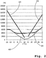
- Figure 2 shows a graphic representation of, in particular, heating and cooling requirements for a bus depending on the ambient temperature and the setpoint of the vehicle interior temperature. Based on the calculated heating and cooling requirements such as heating requirement 10 and cooling requirement 20 as output in watts (W), a bus occupied by twenty-two people with a fresh air volume per hour of 870 m 3 / h is common with a target vehicle interior temperature of 22 ° C insulated body. It can be seen that in the outside temperature range of -15 ° C to 10 ° C the Heating requirement 10 by a system for heating the air for and / or in the (n) / m vehicle interior drops from approx. 17,000 W to approx. 1000 W linearly.
- W watts
- the cooling requirement 20 increases linearly through a system for cooling the air for and / or in the vehicle interior from approx. 2,000 W to approx. 15,000 W at an outside temperature of 35 ° C.
- One thermal store of the system according to the invention serves as a heat store and is thermally coupled to the high pressure area of the refrigerant circuit of the system according to the invention, and the other thermal store serves as a cold store and is on thermally coupled the low-pressure range of the refrigerant circuit of the system according to the invention.
- the system is regulated by means of the controller in such a way that the lower the heat requirement, i.e. the higher the outside temperature at which heating is still required from the system, the power of the at least one compressor is primarily reduced and the heat stored in the thermal store is less important Covering the heat requirement for heating air for and / or in de (n) / m vehicle interior is released in a regulated manner.
- the output of the inventive system is adjusted to the heat demand in the range of low outside temperatures from -15 ° C to approx. -5 ° C, primarily controlled by changing the speed of the compressor in the range from 50 Hz to 30 Hz, so that the The speed of the compressor and thus its performance are contrary to the level of the outside temperature. Only when the outside temperature is higher, from approx. -5 ° C to approx. 12.5 ° C, the higher the outside temperature, the more and more the heating is regulated by the system by releasing the heat stored in the thermal storage tank.
- thermal storage which is subordinate to the regulation of the compressor output, becomes more important towards higher outside temperatures, so their share increases, because the continuous reduction in the compressor output by reducing the speed is limited by the minimum of 30 Hz.
- the relative switch-on time of the compressor and the speed of the compressor continue to behave in the opposite direction to the outside temperature up to a minimum of 30 Hz, until finally in the outside temperature range of approx. 10 ° C to approx. 12.5 ° C
- the thermal storage of the system which is used as heat storage, takes over the heating of the air in the vehicle interior almost completely and the compressor of the refrigerant circuit is only very rarely switched on briefly at the lowest speed of 30 Hz.
- the output and the relative switch-on time of the compressor which is regulated by means of the controller, behave almost reciprocally in relation to the outside temperature when the system is in heat pump operation.
- the system according to the invention is no longer switched to heat pump operation but to air conditioning operation for cooling air for and / or in the vehicle interior.
- the controller controls the system in such a way that the lower the cooling requirement, the priority is the reduction in the output of the compressor and, subordinately, in the further thermal accumulator thermally coupled to the low pressure area of the refrigerant circuit, stored cold to cover the cooling requirement for cooling air for and / or in de (n) / m vehicle interior is released in a controlled manner.
- the output of the inventive system is adjusted to the cooling requirement in the range from high outside temperatures of 35 ° C down to approx.
- the relative switch-on time of the compressor and the speed of the compressor continue to behave in the same direction up to the minimum of 30 Hz, i.e. almost proportionally to the level of the outside temperature, until finally in the outside temperature range of approx. 15 ° C down to approx. 12.5 ° C almost completely the additional thermal storage of the system used as cold storage takes over the cooling of the air in the vehicle interior and the compressor of the refrigerant circuit is only very rarely switched on briefly at the lowest speed of 30 Hz.
- the output and the relative switch-on time of the compressor regulated by means of the control are therefore almost proportional to the level of the outside temperature when the system is in air conditioning.
- Figure 3 shows a further embodiment of a system 1 according to the invention with refrigerant circuit 3 and high pressure control.
- the exemplary embodiment essentially corresponds to the structure in FIG Figure 3 from DE102016110443A1 shown system, however, the system 1 according to the invention has a compressor 5, the performance of which can be regulated, and a controller 45 that controls the performance of the system 1 both by regulating the compressor power and by regulating the Refrigerant shift and thus the high pressure of the refrigerant in the high pressure area of the refrigerant circuit 3 controls.
- the system 1 according to the invention and its control of the high pressure are designed to reduce the high pressure compared to the pressure value of a non-reduced high pressure by a controllable pressure value in the range of up to 50% of the design high pressure (PS) or within a sub-range thereof, the pressure value the high pressure of the refrigerant is higher than that of the evaporation pressure at 20 ° C.
- the refrigerant carbon dioxide CO2 With the refrigerant carbon dioxide CO2, the evaporation pressure at 20 ° C is approx. 55 bar.
- the design high pressure (PS) in the system 1 of the exemplary embodiment is 150 bar. Co2 is used as the refrigerant.
- design high pressures normally between 120 bar and 180 bar are conceivable.
- the design high pressure is normally between 25 bar and 40 bar.
- the evaporation pressure at 20 ° C for refrigerant R-134a is approx. 5.72 bar and for refrigerant R-1234yf approx. 5.92 bar.
- the refrigerant circuit 3 of the system 1 is divided after the controllable compressor 5 at the junction 9 into two refrigerant line branches.
- the first refrigerant line branch leads through the valve 51 designed as a solenoid valve, through the gas cooler area 11 of the heat exchanger 13 which can be operated as a gas cooler, through the further valve 17 designed as a solenoid valve to the controllable one Expansion valve designed expansion member 19, which is used to relax the refrigerant.
- the high pressure area of the refrigerant circuit 3 extends after the expansion element 19 in the refrigerant line is followed by the evaporator area 53 of the further heat exchanger 21, which can be operated as an evaporator this refrigerant line branch of the refrigerant circuit 3 from the expansion element 19 to the suction inlet of the compressor 5.
- the second refrigerant line runs from the branch 9 through the valve 55 designed as a solenoid valve, through the gas cooler area 57 of the further heat exchanger 21, which can also be operated as a gas cooler, through the further valve 33 designed as a solenoid valve to the expansion element 35 designed as a controllable expansion valve, which is used to relax the refrigerant serves. From the compressor 5 to there, the high pressure area of the refrigerant circuit 3 extends in this second refrigerant line branch.
- the heat exchanger 13, which can be operated as a gas cooler, can thus be operated as an evaporator and that as an evaporator further heat exchanger 21 can be operated as a gas cooler in a switchable manner.
- One of the two heat exchangers 13, 21 is an outside air heat exchanger and the other is a refrigerant-air heat exchanger which is provided for heating or cooling air for and / or in at least one part of a vehicle interior.
- the output of the compressor 5 is controlled via its speed.
- Other such as to are also conceivable as variants of the compressor and its control Figure 1 types of control of the compressor output described.
- the controller 45 also controls the high pressure of the refrigerant in the high pressure area of the refrigerant circuit 3 by switching the valves 51, 17, 55, 33 accordingly one of the two heat exchangers 13, 21 is displaced into or out of a gas cooler area 11 or 57 of one of the two heat exchangers 13, 21 that is momentarily otherwise unused in the refrigerant circuit 3.
- valves 51, 17 and 55 are open and valve 33 is closed, refrigerant is shifted to the otherwise unused gas cooler area 57 of heat exchanger 21 in the currently operated refrigerant circuit.
- valve 55 is closed later and valve 33 is open, refrigerant flows out of gas cooler area 57 again.
- the mass of refrigerant in the refrigerant line branch through which refrigerant is flowing can be regulated and thus also the high pressure in the high-pressure area of the refrigerant line branch of the refrigerant circuit 3 through which it flows, or in comparison to the pressure value of a Reduce the non-reduced high pressure by an adjustable pressure value.
- the controller 45 is designed so that it can be used to control the system 1 during heat pump operation, so that the lower the heat demand, i.e. in particular the higher the outside temperature, the power of the compressor 5 is primarily reduced and the lower the high pressure of the refrigerant in the high pressure range of the refrigerant circuit 3 is reduced.
- the performance of the compressor 5 behaves in the opposite direction, preferably reciprocally, to the level of the outside temperature in the heat pump operation of the system 1.
- the controller 45 is also designed so that it can be used to control the system 1 during air conditioning operation in such a way that the lower the cooling requirement, i.e.
- Figure 4 shows an electric or hybrid vehicle 71 as an electric or hybrid bus with an exemplary embodiment of a system 1 according to the invention for heating and cooling air for and in the passenger area and the driver's seat area of the vehicle interior 73.
- FIG 5 is a flow chart of a method for controlling the in Figure 1 shown embodiment of an inventive system for heating or cooling air for and / or in at least one (n) / m part of a vehicle interior of an electric or hybrid vehicle.
- the heating or cooling requirement is determined.
- the control for the system receives the value of the current outside temperature, i.e. the value of the ambient temperature, from an outside temperature sensor in the vehicle.
- the control system for the system also receives the temperature of the air in the part of the vehicle interior that is to be heated or cooled, such as the passenger compartment.
- the control determines the heating or cooling requirement.
- step 105 If no cooling or heating requirement is determined, ie "No” in step 105, the method begins again. Otherwise, ie "Yes” in step 105, the controller sets the system to air conditioning operation in the following step 110, if there is a cooling demand, ie "K", and to heat pump operation, if there is a heating demand, ie "H".
- the heat exchanger located in the low pressure area of the refrigerant circuit is primarily used as an evaporator in the refrigerant circuit of the system for cooling the coolant in the secondary cooling circuit for cooling air for and / or in at least one part of the vehicle interior.
- the system's secondary heating circuit is either switched off or only dissipates heat from the refrigerant to the outside, for example via its own outside air heat exchanger.
- the output of the compressor of the refrigerant circuit of the system is regulated by the controller.
- the level of the output of the compressor behaves in the same way as the level of the outside temperature or the level of the difference between the outside temperature and the setpoint of the temperature of the air in the vehicle interior. So when the outside temperature is very high, the output of the compressor is set high. When regulating the speed of the compressor, it then runs at the maximum speed of, for example, 50 Hz.
- the compressor With other types of control of the output of the compressor, such as via a short-circuit connection of refrigerant between cylinders of the compressor by means of a controllable valve and / or by shutting off the suction chamber of the compressor by means of a controllable valve, the compressor would accordingly be regulated to full power at a very high outside temperature.
- the controller uses the cooling requirement to determine whether secondary cooling by means of stored cold in the thermal store functioning as a cold store is efficient or advantageous for cooling.
- step 140 determines in the following step 140 by receiving measurement data from the thermal store functioning as a cold store whether enough cold is stored there or whether there is still sufficient heat storage capacity. If “No” in step 140, the method begins anew, in which case at A new cycle also takes into account a storage of cold in the thermal storage that functions as a cold storage. If “yes” in step 140, the controller in the following step 150 regulates the lower the cooling requirement, the more subordinate cooling is used by the controller by regulating the release of stored cold in the thermal store of the system used as a cold store.
- the cold stored in the thermal accumulator functioning as a cold accumulator is no longer released cumulatively with the cooling via the refrigerant circuit when the regulated compressor is switched on, but alternates with it, with the relative switch-on time of the regulated compressor becoming lower the lower the cooling requirement, In other words, the times during which cooling takes place solely through released cold from the thermal storage system, which acts as a cold store, is becoming longer.
- the release in the thermal storage of the system which acts as a cold storage, is also regulated indirectly. After a time interval of, for example, 1 second, the process starts anew.
- the controller sets the system to heat pump operation in step 110 when there is a heating requirement "H"
- the heat exchanger provided for heat exchange from the high pressure area of the refrigerant circuit with the secondary heating circuit for heating in the secondary heating circuit for heating air for and / or in at least one (n) / m part of the vehicle interior is used.
- the secondary cooling circuit of the system is either switched off or absorbs heat from the refrigerant solely for cooling, for example, the battery for driving the vehicle and / or for discharging it to the outside.
- the output of the compressor of the refrigerant circuit of the system is regulated by the controller.
- the level of output of the compressor behaves in the opposite direction, preferably reciprocally, to the level of the outside temperature or in the same direction as to the level of the difference that the outside temperature is below the setpoint of the temperature of the air in the vehicle interior. So when the outside temperature is very low, the compressor output is set high. When regulating the speed of the compressor, it then runs at the maximum speed of, for example, 50 Hz. With other types of control of the output of the compressor, such as via short-circuit connection of refrigerant between cylinders of the compressor using a controllable valve and / or blocking the suction chamber of the compressor using controllable valve, the compressor would be regulated to full capacity at a very low outside temperature.
- the heating output of the system is lower or at least it compensates for the heating output that would otherwise increase in the system due to the higher outside temperature due to the higher heating efficiency.
- the lower the heating requirement the lower the output of the system Only inefficiently regulate in heat pump operation and with the increasing risk of damage to the compressor, only reduce the output of the compressor. For example, when regulating the output of the compressor via its speed, there is a minimum of, for example, 30 Hz of the speed to be set. Even an additional, only compressor-side regulation via the relative switch-on time of the compressor is increasingly inefficient in the case of low heating requirements.
- step 130A the controller uses the determined heating requirement to determine whether subordinate heating using stored heat in the thermal store with phase change material as a heat store, which acts as a heat store and is thermally coupled to the high pressure area of the refrigerant circuit of the system, is efficient or advantageous. If “No”, the method starts again after a certain time interval and if "Yes”, the controller determines in the following step 140A by receiving measurement data from the thermal storage device functioning as a heat storage device whether sufficient heat, such as latent heat in particular, is stored there. If “No” in step 140A, the method starts again after a predetermined time interval, with storage of heat in the thermal store functioning as a heat store then also being taken into account when it is repeated.
- step 150A regulates the lower the heating requirement, the increasingly subordinate heating to regulating the compressor output through the regulated release of stored heat from the thermal store of the system used as a heat store by the control used.
- the heat stored in the thermal store functioning as a heat store is no longer released cumulatively with heating via the refrigerant circuit by a heat exchanger operated as a condenser or gas cooler with the regulated compressor switched on, but alternately, whereby the relative switch-on time of the regulated compressor, the lower the heating requirement, the lower the longer, i.e. the times during which heating takes place solely through released heat from the thermal storage tank, which acts as a heat store.
- the release in the thermal storage of the system which functions as a heat storage, is also regulated indirectly. After a time interval of, for example, 1 second, the process starts anew.
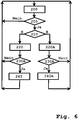
- FIG 6 is a flow chart of a method for controlling the in Figure 3 shown embodiment of an inventive system for heating or cooling air for and / or in at least one (n) / m part of a vehicle interior of an electric or hybrid vehicle.
- the method steps 200, 205, 210, 220 and 220A essentially correspond to those Figure 5 described method steps 100, 105, 110, 120 and 120A, but in this embodiment no secondary heating circuit and no secondary cooling circuit are present, but the first heat exchanger used for the temperature control of air for and / or in the vehicle interior A refrigerant-air heat exchanger that directly cools or heats the air, depending on whether it is set as an evaporator or as a gas cooler in method step 210.
- the second heat exchanger of the refrigerant circuit is an outside air heat exchanger, which is set opposite to the first heat exchanger as a gas cooler or evaporator in method step 210.
- the controller uses the cooling requirement to determine in step 230 whether a cooling regulation that is subordinate to the regulation of the compressor output by reducing the high pressure of the refrigerant in the high pressure area of the refrigerant circuit is efficient or advantageous for cooling. If “No”, the method starts again after a predetermined time interval and if "Yes”, the controller regulates in step 240, the lower the cooling requirement, the systems in such a way that the cooling control, which is subordinate to the regulation of the compressor output, is increasingly controlled by lowering the High pressure of the refrigerant is used in the high pressure area of the refrigerant circuit.
- the high pressure is lowered further down to the minimum high pressure that can be set in this exemplary embodiment of the system with the refrigerant, i.e. the high pressure of the refrigerant reduces by up to 50% of the design high pressure (PS) compared to the pressure value of a non-reduced high pressure however, the pressure value of the high pressure of the refrigerant is above that of the evaporation pressure of the refrigerant at 20 ° C.
- PS design high pressure
- the high pressure is lowered by regulating the displacement of refrigerant into the gas cooler area of the first heat exchanger of the system used for cooling the air for the vehicle interior.
- the controller controls one valve upstream and the other valve downstream of the gas cooler area of the first heat exchanger accordingly. After a time interval of, for example, 1 second, the process starts anew.
- the controller uses the heating requirement to determine in step 230A whether heating control, which is subordinate to the control of the compressor output, by reducing the high pressure of the refrigerant in the high pressure area of the refrigerant circuit is efficient or advantageous. If “No” the method starts again and if “Yes” the controller regulates in step 240A, the lower the heating requirement, the systems in such a way that the heating control, which is subordinate to the regulation of the compressor output, is increasingly controlled by lowering the high pressure of the refrigerant in the High pressure area of the refrigerant circuit is used.
- the high pressure is lowered further down to the minimum high pressure that can be set in this exemplary embodiment of the system with the refrigerant, i.e. the high pressure of the refrigerant reduces by up to 50% of the design high pressure (PS) compared to the pressure value of a non-reduced high pressure however, the pressure value of the high pressure of the refrigerant is above that of the evaporation pressure of the refrigerant at 20 ° C.
- PS design high pressure
- the high pressure is lowered by regulating the displacement of refrigerant into the gas cooler area of the system's second heat exchanger used as an outside air heat exchanger, which is otherwise unused during heating.
- the controller controls one valve upstream and the other valve downstream of the gas cooler area of the second heat exchanger accordingly. After a time interval of, for example, 1 second, the process starts anew.
- a method for the corresponding control of a system according to the invention is also conceivable which comprises a combination of the two in Figure 1 and Figure 3
- the embodiments shown are, that is, with primarily controllable compressor power and thermal accumulators that can be coupled to the refrigerant circuit according to the invention and control of the high pressure according to the invention in the high pressure area of the refrigerant circuit through refrigerant displacement.
Landscapes
- Engineering & Computer Science (AREA)
- Physics & Mathematics (AREA)
- Thermal Sciences (AREA)
- Mechanical Engineering (AREA)
- Life Sciences & Earth Sciences (AREA)
- Sustainable Development (AREA)
- Sustainable Energy (AREA)
- General Engineering & Computer Science (AREA)
- Air-Conditioning For Vehicles (AREA)
Applications Claiming Priority (1)
| Application Number | Priority Date | Filing Date | Title |
|---|---|---|---|
| DE102019105035.9A DE102019105035A1 (de) | 2019-02-27 | 2019-02-27 | Wärmepumpe mit Teillastregelung |
Publications (2)
| Publication Number | Publication Date |
|---|---|
| EP3702181A1 true EP3702181A1 (fr) | 2020-09-02 |
| EP3702181B1 EP3702181B1 (fr) | 2022-06-15 |
Family
ID=69701071
Family Applications (1)
| Application Number | Title | Priority Date | Filing Date |
|---|---|---|---|
| EP20157888.7A Active EP3702181B1 (fr) | 2019-02-27 | 2020-02-18 | Pompe à chaleur à régulation partielle de la charge |
Country Status (4)
| Country | Link |
|---|---|
| EP (1) | EP3702181B1 (fr) |
| CN (1) | CN111619305B (fr) |
| DE (1) | DE102019105035A1 (fr) |
| PL (1) | PL3702181T3 (fr) |
Cited By (3)
| Publication number | Priority date | Publication date | Assignee | Title |
|---|---|---|---|---|
| CN112706693A (zh) * | 2020-12-25 | 2021-04-27 | 一汽奔腾轿车有限公司 | 一种控制后视镜加热刮水的方法 |
| US20220242197A1 (en) * | 2021-02-02 | 2022-08-04 | Mahle International Gmbh | Refrigerant system with two inner heat exchangers |
| EP4257382A1 (fr) * | 2022-04-07 | 2023-10-11 | Konvekta Aktiengesellschaft | Procédé de fonctionnement d'une pompe à chaleur à régulation haute pression et installation de chauffage d'un véhicule à cet effet |
Families Citing this family (3)
| Publication number | Priority date | Publication date | Assignee | Title |
|---|---|---|---|---|
| JP2022099627A (ja) * | 2020-12-23 | 2022-07-05 | サンデン・オートモーティブクライメイトシステム株式会社 | 車両用空調装置 |
| DE102021205922A1 (de) | 2021-06-10 | 2022-12-15 | Magna powertrain gmbh & co kg | Wärmepumpenanordnung für ein Hybrid- oder Elektrofahrzeug |
| DE102023110463A1 (de) * | 2023-04-25 | 2024-10-31 | Bayerische Motoren Werke Aktiengesellschaft | Temperiereinrichtung zum Temperieren zumindest eines Teilbereichs eines Kraftfahrzeugs, Verfahren zum Betreiben einer Temperiereinrichtung sowie Kraftfahrzeug |
Citations (14)
| Publication number | Priority date | Publication date | Assignee | Title |
|---|---|---|---|---|
| DE19607032A1 (de) | 1995-03-10 | 1996-09-12 | Lindau Tech Forsch & Entw Gmbh | Verfahren zur Regelung der Leistung einer Anlage für die Kühlung des Fahrgastraumes eines Kraftfahrzeuges |
| DE19609048A1 (de) | 1996-03-08 | 1997-09-11 | Daimler Benz Ag | Heizungs- und Klimatisierungseinrichtung für Kraftfahrzeuge |
| EP1262347A2 (fr) | 2001-05-29 | 2002-12-04 | Behr GmbH & Co. | Circuit de chauffage/réfrigération pour un climatiseur de véhicule à moteur, climatiseur et procédé pour sa commande |
| DE10146477A1 (de) | 2000-09-22 | 2003-02-27 | Sanden Corp | Fahrzeugklimaanlage |
| DE102005017904A1 (de) * | 2004-04-19 | 2005-11-03 | Behr Gmbh & Co. Kg | Verfahren und Vorrichtung zur Regelung eines Kältemittelkreislaufs einer Klimaanlage für ein Fahrzeug |
| DE102006060259A1 (de) | 2005-12-17 | 2007-06-21 | Ixetic Bad Homburg Gmbh | Klimakompressor |
| DE202010007146U1 (de) | 2010-05-26 | 2011-09-07 | Rehau Ag + Co. | Elektrofahrzeug |
| WO2012146368A1 (fr) * | 2011-04-29 | 2012-11-01 | Valeo Systemes Thermiques | Ensemble comprenant un circuit de fluide refrigerant et un circuit de fluide caloporteur |
| DE102012108317A1 (de) | 2012-09-07 | 2014-03-13 | Daimler Ag | Klimaanlage eines Fahrzeugs mit thermischem Speicher, Verfahren zur Optimierung der Betriebsstrategie der Klimaanlage sowie Verwendung einer Komponente eines Fahrzeugs als thermischen Speicher |
| DE102014011343A1 (de) | 2013-09-25 | 2015-03-26 | Ge Jenbacher Gmbh & Co Og | Zylinderkopf |
| DE102014221930A1 (de) | 2014-10-28 | 2016-04-28 | Bayerische Motoren Werke Aktiengesellschaft | Verfahren zur Steuerung und/oder Regelung einer Heiz-Klimaanlage in einem Kraftfahrzeug |
| DE102016006682A1 (de) * | 2016-05-31 | 2017-11-30 | Audi Ag | Verfahren zum Betreiben einer Klimaanlage eines Elektro- oder Hybridfahrzeugs sowie Klimaanlage zur Durchführung des Verfahrens |
| DE102016110443A1 (de) | 2016-06-06 | 2017-12-07 | Konvekta Aktiengesellschaft | Kälteanlage, Kälteanlagensystem und Verfahren mit Kältemittelverlagerung |
| DE102016117545A1 (de) | 2016-09-17 | 2018-03-22 | K o n v e k t a Gesellschaft mit beschränkter Haftung und Co Kommanditgesellschaft Spezialwerk für Fahrzeugkühlung und Klimatisierung | Wärmespeicherheizungsanlage und Verfahren dazu |
Family Cites Families (3)
| Publication number | Priority date | Publication date | Assignee | Title |
|---|---|---|---|---|
| DE102011118162C5 (de) * | 2011-11-10 | 2020-03-26 | Audi Ag | Kombinierte Kälteanlage und Wärmepumpe und Verfahren zum Betreiben der Anlage mit funktionsabhängiger Kältemittelverlagerung innerhalb des Kältemittelkreislaufes |
| JP6073653B2 (ja) * | 2012-11-09 | 2017-02-01 | サンデンホールディングス株式会社 | 車両用空気調和装置 |
| JP6642857B2 (ja) * | 2016-10-18 | 2020-02-12 | 本田技研工業株式会社 | 車両用空調装置 |
-
2019
- 2019-02-27 DE DE102019105035.9A patent/DE102019105035A1/de not_active Withdrawn
-
2020
- 2020-02-18 EP EP20157888.7A patent/EP3702181B1/fr active Active
- 2020-02-18 PL PL20157888.7T patent/PL3702181T3/pl unknown
- 2020-02-27 CN CN202010123042.XA patent/CN111619305B/zh active Active
Patent Citations (14)
| Publication number | Priority date | Publication date | Assignee | Title |
|---|---|---|---|---|
| DE19607032A1 (de) | 1995-03-10 | 1996-09-12 | Lindau Tech Forsch & Entw Gmbh | Verfahren zur Regelung der Leistung einer Anlage für die Kühlung des Fahrgastraumes eines Kraftfahrzeuges |
| DE19609048A1 (de) | 1996-03-08 | 1997-09-11 | Daimler Benz Ag | Heizungs- und Klimatisierungseinrichtung für Kraftfahrzeuge |
| DE10146477A1 (de) | 2000-09-22 | 2003-02-27 | Sanden Corp | Fahrzeugklimaanlage |
| EP1262347A2 (fr) | 2001-05-29 | 2002-12-04 | Behr GmbH & Co. | Circuit de chauffage/réfrigération pour un climatiseur de véhicule à moteur, climatiseur et procédé pour sa commande |
| DE102005017904A1 (de) * | 2004-04-19 | 2005-11-03 | Behr Gmbh & Co. Kg | Verfahren und Vorrichtung zur Regelung eines Kältemittelkreislaufs einer Klimaanlage für ein Fahrzeug |
| DE102006060259A1 (de) | 2005-12-17 | 2007-06-21 | Ixetic Bad Homburg Gmbh | Klimakompressor |
| DE202010007146U1 (de) | 2010-05-26 | 2011-09-07 | Rehau Ag + Co. | Elektrofahrzeug |
| WO2012146368A1 (fr) * | 2011-04-29 | 2012-11-01 | Valeo Systemes Thermiques | Ensemble comprenant un circuit de fluide refrigerant et un circuit de fluide caloporteur |
| DE102012108317A1 (de) | 2012-09-07 | 2014-03-13 | Daimler Ag | Klimaanlage eines Fahrzeugs mit thermischem Speicher, Verfahren zur Optimierung der Betriebsstrategie der Klimaanlage sowie Verwendung einer Komponente eines Fahrzeugs als thermischen Speicher |
| DE102014011343A1 (de) | 2013-09-25 | 2015-03-26 | Ge Jenbacher Gmbh & Co Og | Zylinderkopf |
| DE102014221930A1 (de) | 2014-10-28 | 2016-04-28 | Bayerische Motoren Werke Aktiengesellschaft | Verfahren zur Steuerung und/oder Regelung einer Heiz-Klimaanlage in einem Kraftfahrzeug |
| DE102016006682A1 (de) * | 2016-05-31 | 2017-11-30 | Audi Ag | Verfahren zum Betreiben einer Klimaanlage eines Elektro- oder Hybridfahrzeugs sowie Klimaanlage zur Durchführung des Verfahrens |
| DE102016110443A1 (de) | 2016-06-06 | 2017-12-07 | Konvekta Aktiengesellschaft | Kälteanlage, Kälteanlagensystem und Verfahren mit Kältemittelverlagerung |
| DE102016117545A1 (de) | 2016-09-17 | 2018-03-22 | K o n v e k t a Gesellschaft mit beschränkter Haftung und Co Kommanditgesellschaft Spezialwerk für Fahrzeugkühlung und Klimatisierung | Wärmespeicherheizungsanlage und Verfahren dazu |
Cited By (4)
| Publication number | Priority date | Publication date | Assignee | Title |
|---|---|---|---|---|
| CN112706693A (zh) * | 2020-12-25 | 2021-04-27 | 一汽奔腾轿车有限公司 | 一种控制后视镜加热刮水的方法 |
| US20220242197A1 (en) * | 2021-02-02 | 2022-08-04 | Mahle International Gmbh | Refrigerant system with two inner heat exchangers |
| US11827076B2 (en) * | 2021-02-02 | 2023-11-28 | Mahle International Gmbh | Refrigerant system with two inner heat exchangers |
| EP4257382A1 (fr) * | 2022-04-07 | 2023-10-11 | Konvekta Aktiengesellschaft | Procédé de fonctionnement d'une pompe à chaleur à régulation haute pression et installation de chauffage d'un véhicule à cet effet |
Also Published As
| Publication number | Publication date |
|---|---|
| CN111619305B (zh) | 2023-09-12 |
| PL3702181T3 (pl) | 2022-09-19 |
| DE102019105035A1 (de) | 2020-08-27 |
| CN111619305A (zh) | 2020-09-04 |
| EP3702181B1 (fr) | 2022-06-15 |
Similar Documents
| Publication | Publication Date | Title |
|---|---|---|
| EP3702181B1 (fr) | Pompe à chaleur à régulation partielle de la charge | |
| DE102011118162B4 (de) | Kombinierte Kälteanlage und Wärmepumpe und Verfahren zum Betreiben der Anlage mit funktionsabhängiger Kältemittelverlagerung innerhalb des Kältemittelkreislaufes | |
| EP2519415B1 (fr) | Système de climatisation pour un véhicule et procédé de thermorégulation | |
| EP1397265B1 (fr) | Installation de climatisation | |
| DE19838880C2 (de) | Einrichtung zum Kühlen eines Innenraumes eines Kraftfahrzeugs | |
| DE60123816T2 (de) | Umkehrbare dampfverdichtungsanordnung | |
| DE102012208992B4 (de) | Heiz-/Kühlkreislauf für Fahrzeuge, insbesondere für Hybridfahrzeuge oder reine Elektrofahrzeuge | |
| DE102020105801A1 (de) | Wärmemanagementsystem und integriertes wärmemanagementmodul für ein fahrzeug | |
| DE102014203895B4 (de) | Kälteanlage | |
| DE10141389B4 (de) | Kombinationswärmeübertrager für den Kühlmittelkreislauf eines Kraftfahrzeuges | |
| EP3191328A1 (fr) | Installation de pompe à chaleur permettant la climatisation d'un véhicule et procédé permettant de faire fonctionner une pompe à chaleur de ce type | |
| DE112019006489T5 (de) | Fahrzeugluftkonditioniereinrichtung | |
| DE102006026359A1 (de) | Klimaanlage für Fahrzeuge sowie Verfahren zum Betrieb hierzu | |
| EP1262347A2 (fr) | Circuit de chauffage/réfrigération pour un climatiseur de véhicule à moteur, climatiseur et procédé pour sa commande | |
| DE102018113687B4 (de) | Vorrichtung und Verfahren zur Kühlung von Batteriezellenmodulen | |
| DE102021104972A1 (de) | Heizungs- und Klimaanlage mit verschiedenen Temperaturniveaus für ein Fahrzeug und Verfahren dazu | |
| DE112016003261T5 (de) | Klimaanlagengerät für Fahrzeuge | |
| DE102010024775B4 (de) | Vorrichtung zur Klimatisierung von Fahrzeugen | |
| WO2021094054A1 (fr) | Procédé pour la gestion thermique d'un véhicule à moteur | |
| DE102022117374B4 (de) | Verfahren zur Regelung eines Thermomanagementsystems für Elektrofahrzeuge | |
| WO2021018501A1 (fr) | Système de gestion thermique pour un véhicule à moteur, procédé pour la gestion thermique d'un véhicule à moteur et véhicule à moteur ayant un système de gestion thermique | |
| DE102016213619A1 (de) | Verfahren zum betrieb eines klimasystems sowie klimasystem | |
| EP4257382B1 (fr) | Procédé de fonctionnement d'une pompe à chaleur à régulation haute pression et installation de chauffage d'un véhicule à cet effet | |
| DD240061A5 (de) | Zwillingsspeicher im waermeuebergangskreislauf | |
| DE102014105612B4 (de) | Fahrzeug-Klimasystem und Verfahren zum Betrieb eines Fahrzeug-Klimasystems |
Legal Events
| Date | Code | Title | Description |
|---|---|---|---|
| PUAI | Public reference made under article 153(3) epc to a published international application that has entered the european phase |
Free format text: ORIGINAL CODE: 0009012 |
|
| STAA | Information on the status of an ep patent application or granted ep patent |
Free format text: STATUS: THE APPLICATION HAS BEEN PUBLISHED |
|
| AK | Designated contracting states |
Kind code of ref document: A1 Designated state(s): AL AT BE BG CH CY CZ DE DK EE ES FI FR GB GR HR HU IE IS IT LI LT LU LV MC MK MT NL NO PL PT RO RS SE SI SK SM TR |
|
| AX | Request for extension of the european patent |
Extension state: BA ME |
|
| STAA | Information on the status of an ep patent application or granted ep patent |
Free format text: STATUS: REQUEST FOR EXAMINATION WAS MADE |
|
| 17P | Request for examination filed |
Effective date: 20210225 |
|
| RBV | Designated contracting states (corrected) |
Designated state(s): AL AT BE BG CH CY CZ DE DK EE ES FI FR GB GR HR HU IE IS IT LI LT LU LV MC MK MT NL NO PL PT RO RS SE SI SK SM TR |
|
| GRAP | Despatch of communication of intention to grant a patent |
Free format text: ORIGINAL CODE: EPIDOSNIGR1 |
|
| STAA | Information on the status of an ep patent application or granted ep patent |
Free format text: STATUS: GRANT OF PATENT IS INTENDED |
|
| RIC1 | Information provided on ipc code assigned before grant |
Ipc: B60H 1/32 20060101ALI20220126BHEP Ipc: B60H 1/00 20060101AFI20220126BHEP |
|
| INTG | Intention to grant announced |
Effective date: 20220211 |
|
| GRAS | Grant fee paid |
Free format text: ORIGINAL CODE: EPIDOSNIGR3 |
|
| GRAA | (expected) grant |
Free format text: ORIGINAL CODE: 0009210 |
|
| STAA | Information on the status of an ep patent application or granted ep patent |
Free format text: STATUS: THE PATENT HAS BEEN GRANTED |
|
| AK | Designated contracting states |
Kind code of ref document: B1 Designated state(s): AL AT BE BG CH CY CZ DE DK EE ES FI FR GB GR HR HU IE IS IT LI LT LU LV MC MK MT NL NO PL PT RO RS SE SI SK SM TR |
|
| REG | Reference to a national code |
Ref country code: CH Ref legal event code: EP Ref country code: GB Ref legal event code: FG4D Free format text: NOT ENGLISH |
|
| REG | Reference to a national code |
Ref country code: IE Ref legal event code: FG4D Free format text: LANGUAGE OF EP DOCUMENT: GERMAN |
|
| REG | Reference to a national code |
Ref country code: DE Ref legal event code: R096 Ref document number: 502020001223 Country of ref document: DE |
|
| REG | Reference to a national code |
Ref country code: AT Ref legal event code: REF Ref document number: 1498160 Country of ref document: AT Kind code of ref document: T Effective date: 20220715 |
|
| REG | Reference to a national code |
Ref country code: LT Ref legal event code: MG9D |
|
| REG | Reference to a national code |
Ref country code: NL Ref legal event code: MP Effective date: 20220615 |
|
| PG25 | Lapsed in a contracting state [announced via postgrant information from national office to epo] |
Ref country code: SE Free format text: LAPSE BECAUSE OF FAILURE TO SUBMIT A TRANSLATION OF THE DESCRIPTION OR TO PAY THE FEE WITHIN THE PRESCRIBED TIME-LIMIT Effective date: 20220615 Ref country code: NO Free format text: LAPSE BECAUSE OF FAILURE TO SUBMIT A TRANSLATION OF THE DESCRIPTION OR TO PAY THE FEE WITHIN THE PRESCRIBED TIME-LIMIT Effective date: 20220915 Ref country code: LT Free format text: LAPSE BECAUSE OF FAILURE TO SUBMIT A TRANSLATION OF THE DESCRIPTION OR TO PAY THE FEE WITHIN THE PRESCRIBED TIME-LIMIT Effective date: 20220615 Ref country code: HR Free format text: LAPSE BECAUSE OF FAILURE TO SUBMIT A TRANSLATION OF THE DESCRIPTION OR TO PAY THE FEE WITHIN THE PRESCRIBED TIME-LIMIT Effective date: 20220615 Ref country code: GR Free format text: LAPSE BECAUSE OF FAILURE TO SUBMIT A TRANSLATION OF THE DESCRIPTION OR TO PAY THE FEE WITHIN THE PRESCRIBED TIME-LIMIT Effective date: 20220916 Ref country code: FI Free format text: LAPSE BECAUSE OF FAILURE TO SUBMIT A TRANSLATION OF THE DESCRIPTION OR TO PAY THE FEE WITHIN THE PRESCRIBED TIME-LIMIT Effective date: 20220615 Ref country code: BG Free format text: LAPSE BECAUSE OF FAILURE TO SUBMIT A TRANSLATION OF THE DESCRIPTION OR TO PAY THE FEE WITHIN THE PRESCRIBED TIME-LIMIT Effective date: 20220915 |
|
| PG25 | Lapsed in a contracting state [announced via postgrant information from national office to epo] |
Ref country code: RS Free format text: LAPSE BECAUSE OF FAILURE TO SUBMIT A TRANSLATION OF THE DESCRIPTION OR TO PAY THE FEE WITHIN THE PRESCRIBED TIME-LIMIT Effective date: 20220615 Ref country code: LV Free format text: LAPSE BECAUSE OF FAILURE TO SUBMIT A TRANSLATION OF THE DESCRIPTION OR TO PAY THE FEE WITHIN THE PRESCRIBED TIME-LIMIT Effective date: 20220615 |
|
| PG25 | Lapsed in a contracting state [announced via postgrant information from national office to epo] |
Ref country code: NL Free format text: LAPSE BECAUSE OF FAILURE TO SUBMIT A TRANSLATION OF THE DESCRIPTION OR TO PAY THE FEE WITHIN THE PRESCRIBED TIME-LIMIT Effective date: 20220615 |
|
| PG25 | Lapsed in a contracting state [announced via postgrant information from national office to epo] |
Ref country code: SM Free format text: LAPSE BECAUSE OF FAILURE TO SUBMIT A TRANSLATION OF THE DESCRIPTION OR TO PAY THE FEE WITHIN THE PRESCRIBED TIME-LIMIT Effective date: 20220615 Ref country code: SK Free format text: LAPSE BECAUSE OF FAILURE TO SUBMIT A TRANSLATION OF THE DESCRIPTION OR TO PAY THE FEE WITHIN THE PRESCRIBED TIME-LIMIT Effective date: 20220615 Ref country code: RO Free format text: LAPSE BECAUSE OF FAILURE TO SUBMIT A TRANSLATION OF THE DESCRIPTION OR TO PAY THE FEE WITHIN THE PRESCRIBED TIME-LIMIT Effective date: 20220615 Ref country code: PT Free format text: LAPSE BECAUSE OF FAILURE TO SUBMIT A TRANSLATION OF THE DESCRIPTION OR TO PAY THE FEE WITHIN THE PRESCRIBED TIME-LIMIT Effective date: 20221017 Ref country code: ES Free format text: LAPSE BECAUSE OF FAILURE TO SUBMIT A TRANSLATION OF THE DESCRIPTION OR TO PAY THE FEE WITHIN THE PRESCRIBED TIME-LIMIT Effective date: 20220615 Ref country code: EE Free format text: LAPSE BECAUSE OF FAILURE TO SUBMIT A TRANSLATION OF THE DESCRIPTION OR TO PAY THE FEE WITHIN THE PRESCRIBED TIME-LIMIT Effective date: 20220615 Ref country code: CZ Free format text: LAPSE BECAUSE OF FAILURE TO SUBMIT A TRANSLATION OF THE DESCRIPTION OR TO PAY THE FEE WITHIN THE PRESCRIBED TIME-LIMIT Effective date: 20220615 |
|
| PG25 | Lapsed in a contracting state [announced via postgrant information from national office to epo] |
Ref country code: IS Free format text: LAPSE BECAUSE OF FAILURE TO SUBMIT A TRANSLATION OF THE DESCRIPTION OR TO PAY THE FEE WITHIN THE PRESCRIBED TIME-LIMIT Effective date: 20221015 |
|
| REG | Reference to a national code |
Ref country code: DE Ref legal event code: R097 Ref document number: 502020001223 Country of ref document: DE |
|
| PG25 | Lapsed in a contracting state [announced via postgrant information from national office to epo] |
Ref country code: AL Free format text: LAPSE BECAUSE OF FAILURE TO SUBMIT A TRANSLATION OF THE DESCRIPTION OR TO PAY THE FEE WITHIN THE PRESCRIBED TIME-LIMIT Effective date: 20220615 |
|
| PLBE | No opposition filed within time limit |
Free format text: ORIGINAL CODE: 0009261 |
|
| STAA | Information on the status of an ep patent application or granted ep patent |
Free format text: STATUS: NO OPPOSITION FILED WITHIN TIME LIMIT |
|
| PG25 | Lapsed in a contracting state [announced via postgrant information from national office to epo] |
Ref country code: DK Free format text: LAPSE BECAUSE OF FAILURE TO SUBMIT A TRANSLATION OF THE DESCRIPTION OR TO PAY THE FEE WITHIN THE PRESCRIBED TIME-LIMIT Effective date: 20220615 |
|
| 26N | No opposition filed |
Effective date: 20230316 |
|
| PG25 | Lapsed in a contracting state [announced via postgrant information from national office to epo] |
Ref country code: SI Free format text: LAPSE BECAUSE OF FAILURE TO SUBMIT A TRANSLATION OF THE DESCRIPTION OR TO PAY THE FEE WITHIN THE PRESCRIBED TIME-LIMIT Effective date: 20220615 |
|
| PG25 | Lapsed in a contracting state [announced via postgrant information from national office to epo] |
Ref country code: MC Free format text: LAPSE BECAUSE OF FAILURE TO SUBMIT A TRANSLATION OF THE DESCRIPTION OR TO PAY THE FEE WITHIN THE PRESCRIBED TIME-LIMIT Effective date: 20220615 |
|
| REG | Reference to a national code |
Ref country code: BE Ref legal event code: MM Effective date: 20230228 |
|
| PG25 | Lapsed in a contracting state [announced via postgrant information from national office to epo] |
Ref country code: LU Free format text: LAPSE BECAUSE OF NON-PAYMENT OF DUE FEES Effective date: 20230218 |
|
| REG | Reference to a national code |
Ref country code: IE Ref legal event code: MM4A |
|
| PG25 | Lapsed in a contracting state [announced via postgrant information from national office to epo] |
Ref country code: IT Free format text: LAPSE BECAUSE OF FAILURE TO SUBMIT A TRANSLATION OF THE DESCRIPTION OR TO PAY THE FEE WITHIN THE PRESCRIBED TIME-LIMIT Effective date: 20220615 Ref country code: IE Free format text: LAPSE BECAUSE OF NON-PAYMENT OF DUE FEES Effective date: 20230218 |
|
| PG25 | Lapsed in a contracting state [announced via postgrant information from national office to epo] |
Ref country code: BE Free format text: LAPSE BECAUSE OF NON-PAYMENT OF DUE FEES Effective date: 20230228 |
|
| PG25 | Lapsed in a contracting state [announced via postgrant information from national office to epo] |
Ref country code: BG Free format text: LAPSE BECAUSE OF FAILURE TO SUBMIT A TRANSLATION OF THE DESCRIPTION OR TO PAY THE FEE WITHIN THE PRESCRIBED TIME-LIMIT Effective date: 20220615 |
|
| PG25 | Lapsed in a contracting state [announced via postgrant information from national office to epo] |
Ref country code: BG Free format text: LAPSE BECAUSE OF FAILURE TO SUBMIT A TRANSLATION OF THE DESCRIPTION OR TO PAY THE FEE WITHIN THE PRESCRIBED TIME-LIMIT Effective date: 20220615 |
|
| PG25 | Lapsed in a contracting state [announced via postgrant information from national office to epo] |
Ref country code: CY Free format text: LAPSE BECAUSE OF FAILURE TO SUBMIT A TRANSLATION OF THE DESCRIPTION OR TO PAY THE FEE WITHIN THE PRESCRIBED TIME-LIMIT; INVALID AB INITIO Effective date: 20200218 |
|
| PG25 | Lapsed in a contracting state [announced via postgrant information from national office to epo] |
Ref country code: HU Free format text: LAPSE BECAUSE OF FAILURE TO SUBMIT A TRANSLATION OF THE DESCRIPTION OR TO PAY THE FEE WITHIN THE PRESCRIBED TIME-LIMIT; INVALID AB INITIO Effective date: 20200218 |
|
| PG25 | Lapsed in a contracting state [announced via postgrant information from national office to epo] |
Ref country code: TR Free format text: LAPSE BECAUSE OF FAILURE TO SUBMIT A TRANSLATION OF THE DESCRIPTION OR TO PAY THE FEE WITHIN THE PRESCRIBED TIME-LIMIT Effective date: 20220615 |
|
| PGFP | Annual fee paid to national office [announced via postgrant information from national office to epo] |
Ref country code: PL Payment date: 20251218 Year of fee payment: 7 |
|
| REG | Reference to a national code |
Ref country code: CH Ref legal event code: U11 Free format text: ST27 STATUS EVENT CODE: U-0-0-U10-U11 (AS PROVIDED BY THE NATIONAL OFFICE) Effective date: 20260301 |
|
| PGFP | Annual fee paid to national office [announced via postgrant information from national office to epo] |
Ref country code: GB Payment date: 20260203 Year of fee payment: 7 |
|
| PGFP | Annual fee paid to national office [announced via postgrant information from national office to epo] |
Ref country code: DE Payment date: 20260228 Year of fee payment: 7 |
|
| PGFP | Annual fee paid to national office [announced via postgrant information from national office to epo] |
Ref country code: AT Payment date: 20260212 Year of fee payment: 7 |
|
| PGFP | Annual fee paid to national office [announced via postgrant information from national office to epo] |
Ref country code: FR Payment date: 20260114 Year of fee payment: 7 |
|
| PGFP | Annual fee paid to national office [announced via postgrant information from national office to epo] |
Ref country code: CH Payment date: 20260301 Year of fee payment: 7 |