EP3702505B1 - Aiguille à coulisse pour une machine à tricoter rectiligne - Google Patents
Aiguille à coulisse pour une machine à tricoter rectiligne Download PDFInfo
- Publication number
- EP3702505B1 EP3702505B1 EP20159208.6A EP20159208A EP3702505B1 EP 3702505 B1 EP3702505 B1 EP 3702505B1 EP 20159208 A EP20159208 A EP 20159208A EP 3702505 B1 EP3702505 B1 EP 3702505B1
- Authority
- EP
- European Patent Office
- Prior art keywords
- needle
- main
- sleeve
- main needle
- hook
- Prior art date
- Legal status (The legal status is an assumption and is not a legal conclusion. Google has not performed a legal analysis and makes no representation as to the accuracy of the status listed.)
- Active
Links
Images



Classifications
-
- D—TEXTILES; PAPER
- D04—BRAIDING; LACE-MAKING; KNITTING; TRIMMINGS; NON-WOVEN FABRICS
- D04B—KNITTING
- D04B35/00—Details of, or auxiliary devices incorporated in, knitting machines, not otherwise provided for
- D04B35/02—Knitting tools or instruments not provided for in group D04B15/00 or D04B27/00
- D04B35/06—Sliding-tongue needles
Definitions
- the present invention belongs to the technical field of knitting machinery, in particular to a compound needle in a flat knitting machine.
- a latch needle in the prior art has a needle latch that is rotatable on a needle bar. Actions of looping, knocking-over, tucking, clearing, needle turning, needle connecting and the like of a loop by the needle latch are completed by opening and closing of the needle latch in combination with a main needle and yarns. Since the rotation of the needle latch requires space, a reed is disposed at a needle turning position of the main needle, such that this latch needle requires a larger vertical stroke to complete these knitting functions.
- the opening action of the needle latch also needs to be completed by means of a hairbrush or yarns. If the hairbrush is not appropriate or the installation position is not in place, defects such as missing needles are likely to occur, and the life and installation accuracy requirements on the hairbrush are relatively high.
- the compound needle comprises a main needle and a needle sleeve sleeving the main needle.
- the main needle is divided into three parts: a head portion, a middle portion and a tail portion, wherein the head portion has a needle hook, a stop end is disposed at a junction between the middle portion and the tail portion, an elongated limiting bar is disposed on the right side of the middle portion of the main needle, and the limiting bar and the front end of the middle portion form a U-shaped structure; the right side of the junction between the head portion and the middle portion of the main needle protrudes outwards to form a bump, and the left side thereof relative to the right side is bent inwards to form an inwards-recessed make-way groove; an inwards-recessed needle groove is formed in the front side and the rear side of the bump; the needle sleeve is divided into a front section, a main section and
- US2002112509 discloses a similar structure of a compound needle as in CN201810043037 .
- the compound needle having such a structure can complete the actions of clearing, looping, needle turning, needle connecting and the like of the loop by virtue of the cooperation of the main needle and the needle sleeve, thereby being capable of substituting for the needle latch.
- the structure of the main needle is too complicated, and the requirement on the processing precision of the main needle and the needle sleeve is high.
- the apex angle of the needle sleeve is inclined towards the main needle, so that when the apex angle closes the hook, the width of the closed position is increased, and therefore, the passing loop becomes large, which affects the knitting effect.
- An objective of the present invention is to provide a compound needle in a flat knitting machine, which has a simple structure and completes clearing, looping, needle turning, needle connecting and other actions of a loop, instead of a latch needle and a main needle.
- a compound needle for a flat knitting machine comprises a main needle and a needle sleeve capable to sleeve the main needle; the main needle is elongated, and a needle hook is disposed at a head portion of the main needle, wherein a direction in which the needle hook is bent is defined as a right side, and a direction opposite to the direction in which the needle hook is bent is defined as a left side; two planes of the main needle perpendicular to the right and left sides are defined as front and back sides; the main needle is provided with a lug boss that protrudes outwards from the right side and is positioned below the needle hook; an inwards-recessed accommodating groove is formed in front and rear sides of the lug boss; the left side of the main needle is bent inwards to form an inwards-recessed make-way groove, wherein, the top end of the needle sleeve is provided with an apex angle which is of a hollow structure; an apex angle which is of a hollow structure; an
- a trajectory surface is formed on one side, facing the needle sleeve, of the main needle; a salient point is formed on one side, facing the main needle, of the needle sleeve; the salient point cooperates with the trajectory surface of the main needle, such that when the needle sleeves moves along the main needle, the apex angle moves from the accommodating grooves of the main needle to close the needle hook of the main needle.
- the trajectory surface of the main needle is positioned below the lug boss and consists of a plurality of smooth concave surfaces and convex surfaces; the trajectory surface is provided with a first notch and a second notch; the salient point on the needle sleeve moves along the trajectory surface; when the apex angle of the needle sleeve is located in the accommodating groove of the main needle, the salient point is positioned at the second notch; when the apex angle of the needle sleeve moves upwards to close the needle hook of the main needle, the salient point is positioned at the first recess.
- a second salient point is formed on one side, facing the main needle, of the tail end of the needle sleeve; the second salient point props against and moves vertically along the right side of the bottom of the main needle.
- a salient point is formed on one side, facing the needle sleeve, of the main needle; a trajectory surface is formed on one side, facing the main needle, of the needle sleeve; the salient point cooperates with the trajectory surface, such that when the needle sleeve moves along the main needle, the apex angle moves from the accommodating grooves of the main needle to close the needle hook of the main needle.
- portions of the side sheets exceeding the intermediate sheet are forming the two sidewalls of the open slot structure, and the middle section of each of two sidewalls of the open slot structure of the needle sleeve is provided with a gap; a first fastener and a second fastener are formed at the upper end and the lower end of each of the two sidewalls; a concave surface on each of the front side and the rear side of the main needle consists of a first concave surface and a second concave surface which are arranged in sections; the first fastener and the second fastener are respectively fastened on the first concave surface and the second concave surface of the main needle.
- a bending direction of the apex angle at the top end of the needle sleeve is consistent with a tilting direction of the tip of the needle hook, that is, the apex is bent towards one side facing away from the main needle; the lower side of the apex angle of the needle sleeve is recessed inwards to form a wiring groove that extends downwards and protrudes outwards to form a limiting end.
- an elastic sheet capable to be pressed by the needle groove is disposed on one side, facing away from the main needle, of the needle sleeve and is of an elongated broken line shape.
- the needle sleeve is composed of an intermediate sheet and two side sheets; the apex angle at the top end of the needle sleeve consists of two side sheets; one side, facing the main needle, of each of two side sheets extends outwards to form two clamping strips; the corresponding clamping strips on the two side sheets form the first fastener and the second fastener.
- the intermediate sheet and the two side sheets of the needle sleeve are assembled and molded after being machined separately, or the intermediate sheet and the two side sheets are integrally machined and molded directly.
- the first fastener and the second fastener on the needle sleeve are positioned at the middle portion and the tail end of the needle sleeve respectively; the front side and the rear side of a position where the trajectory surface of the main needle is located are recessed inwards to form a first concave surface; the first fastener is in tight contact with the first concave surface on the front side and the rear side of the main needle; the tail end of the main needle is provided with a stop end; the front side and the rear side above the stop end are recessed inwards to form a second concave surface; the second fastener is in tight contact with the second concave surface on the front side and the rear side of the main needle.
- the apex angle at the head of the needle sleeve is of a hollow structure, which can guide a knitting needle in the corresponding position to reach a needle turning position, thereby realizing the needle turning action which is simple and convenient.
- the compound needle has the characteristics that a bending direction of the apex angle of the needle sleeve is consistent with a tilting direction of the tip of the needle hook, and the width of the closed position of the needle sleeve and the needle hook is reduced, thereby reducing the knocking-over resistance of the loop, and reducing the size of the knocked-over loop.
- the design in which the needle hook is opened or closed by sliding the needle sleeve also reduces the clearing stroke of the loop, thereby improving the knitting speed of a fabric and improving the production efficiency.
- An elastic sheet is disposed above the needle sleeve and is integrally molded with the intermediate sheet of the needle sleeve.
- This elastic sheet is flexible rather than rigid, and is thus not prone to brakeage.
- the compound needle is always under a pressed state within a needle groove of a needle bed to prevent the needle sleeve from warping upwards.
- there is a reverse buckling function the needle sleeve slides under the simultaneous action of pressing and reverse buckling, such that the double insurance ensures that the compound needle stably slides in the needle groove.
- An inwards-recessed concave surface is respectively formed on the middle portion and the tail portion of the main needle.
- the two sidewalls of the open slot of the needle sleeve are hollowed out, so that the upper and lower ends of the two sidewalls form oppositely bent clamping strips.
- the clamping strips in corresponding positions form a fastener.
- the clamping strips and the two side sheets of the needle sleeve are molded integrally.
- the fastener is part of the needle sleeve.
- the needle sleeve sleeves the main needle by the cooperation of the fastener and the concave surface.
- the needle sleeve slides on the concave surface by the fastener, so that the needle sleeve moves vertically relative to the main needle, thereby closing the needle hook.
- the trajectory contact between the needle sleeve and the main needle can be achieved by point-surface fit or a surface-surface fit.
- the needle sleeve is provided with a salient point and the main needle is provided with a trajectory surface, or the needle sleeve is provided with a trajectory surface and the main needle is provided with a salient point.
- the two principles are the same, i.e., mainly residue in that the salient point moves vertically along the trajectory surface.
- the salient point is used to support the needle sleeve to slide in a pressed state, to reduce the contact area, thereby reducing the frictional force and facilitating smooth sliding of the needle sleeve in the needle groove.
- the tail of the needle sleeve comes into contact with the stop end of the main needle.
- the two side sheets of the needle sleeve are embedded in the accommodating grooves of the main needle, which is beneficial to stabilize the size of the loop.
- the needle sleeve has the same width as the main needle, which not only ensures the strength, but also ensures stable sliding in the needle groove, and is beneficial to stable knitting of a fabric and flatting of the fabric surface.
- the needle hook is opened or closed by sliding of the needle sleeve on the main needle, such that the interaction between the needle sleeve and the main needle completes the traditional actions of looping, knocking-over, tucking and clearing instead of the traditional latch needle, thereby realizing capturing and discharge of the looped yarn.
- the apex angle at the head of the needle sleeve first passes over the needle hook for a certain distance, ensuring that the head of the needle sleeve does not collide with the tip of the needle hook, and then runs downward to prevent the tip of the needle hook from being deformed.
- the two side sheets of the apex angle of the needle sleeve wrap the needle hook.
- the upper surface of the head of the needle sleeve is flush with the upper surface of the needle hook, i.e., the upper surface of the apex angle forms a smooth circular arc structure with an outer curved surface of the needle hook, which reduces the knocking-over resistance of the loop, stabilizes the loop size, and improves the fabric quality.
- Reference symbols in drawings represent the following components: main needle 1; needle hook 11; lug boss 12; make-way groove 13; accommodating groove 14; trajectory surface 15; first notch 151; second notch 152; first concave surface 16; second concave surface 17; stop end 18; needle sleeve 2; apex angle 21; wiring groove 22; limiting end 23; first salient point 24; second salient point 25; first fastener 26; second fastener 27; elastic sheet 28.
- the compound needle of the present embodiment comprises a main needle 1 and a needle sleeve 2 sleeving the main needle.
- the main needle 1 is elongated, and a needle hook 11 is disposed at the head of the main needle.
- a direction in which the needle hook is bent is defined as a right side, and a direction opposite to the direction in which the needle hook is bent is defined as a left side.
- Two planes of the main needle are defined as front and back sides.
- a lug boss 12 that protrudes outwards and is positioned below the needle hook is disposed on the right side of the main needle, and the left side, opposite to the right side, of the main needle is bent inwards to form an inwards-recessed make-way groove 13, such that the size of a range in which the loop slides on the main needle is kept within a certain range to facilitate the movement of the loop on the main needle.
- An inwards-recessed accommodating groove 14 is formed in the front side and the rear side of the lug boss and used for placing the apex of the needle sleeve.
- the lug boss 12 extends downwards to form a trajectory surface 15.
- the trajectory surface 15 consists of a plurality of smooth concave surfaces and convex surfaces. The trajectory surface is uneven depending on the movement requirements of the needle sleeve.
- the upper side of the trajectory surface adjoins to the lug boss.
- a first notch 151 is formed close to the middle position of the trajectory surface, and a second notch 152 is formed in the bottom of the trajectory surface.
- the front side and the rear side of the position where the trajectory surface of the main needle is located are recessed inwards to form a first concave surface 16.
- the thickness of the main needle at the first concave surface becomes smaller, and the thickness of the lower side of the first concave surface is a normal thickness of the main needle.
- a stop end 18 is disposed at the tail end of the main needle. A position close to the stop end is recessed inwards to form a second concave surface 17. The thickness of the main needle at the second concave surface becomes smaller.
- the needle sleeve 2 is composed of an intermediate sheet and two side sheets.
- the intermediate sheet and the two side sheets may be assembled into the needle sleeve after being machined separately, or may be integrally machined and molded directly, for example, milled directly by a lathe.
- a sharp apex angle 21 is disposed on the top end of the needle sleeve.
- the apex angle is of a hollow structure consisting of two side sheets.
- One side, facing the main needle, of the needle sleeve 2 is of an open slot structure, and the remaining portions are of a solid structure respectively.
- a bending direction of the apex angle 21 at the top end of the needle sleeve is consistent with a tilting direction of the tip of the needle hook 11, that is, the apex is bent towards one side facing away from the main needle.
- the lower side of the apex angle 21 of the needle sleeve is recessed inwards to form a wiring groove 22 that extends downwards and protrudes outwards to form a limiting end 23.
- Salient points are formed in one side, facing the main needle, of the needle sleeve.
- the first salient point 24 is located in the middle section of the needle sleeve and props against the trajectory surface on the main needle.
- the second salient point 25 is located on the tail end of the needle sleeve and props against the right side of the tail end of the main needle. The two salient points are used to support the needle sleeve to slide in a pressed state, to reduce the contact area, thereby reducing the frictional force and facilitating smooth sliding of the needle sleeve in the needle groove.
- the open slot of the needle sleeve is composed of two side sheets, or that is to say, the portions, exceeding the intermediate sheet, of the two side sheets form an open slot, and the exceeding portions of the two side sheets are two sidewalls of the open slot.
- the middles of the two sidewalls of the open slot are hollowed out, leaving only the upper and lower ends.
- each of two side sheets extends outwards towards one side of the main needle to form two clamping strips, and two clamping strips on the same side sheet are of oppositely bent structures, which not only reduces the contact area between the needle sleeve and the main needle, but also ensures the movement stability of the needle sleeve.
- the corresponding clamping strips on the two side sheets form a first fastener 16 and a second fastener 17 which are buckled on the first concave surface 16 and the second concave surface 17 on the main needle respectively and slide on the two concave surfaces. Therefore, each of the so-called clamping strips is a part of each of two side sheets of the needle sleeve, and the first fastener 26 and the second fastener 27 are integrally molded with the side sheets of the needle sleeve.
- An elongated elastic sheet 28 which is in a broken line shape is disposed on the right side of the needle sleeve.
- the elastic sheet and the intermediate sheet are integrally molded.
- One end of the elastic sheet is connected to the intermediate sheet, and the other end of the elastic sheet is suspended in a groove formed by the two side sheets. The suspended end under a pressed state may move in this groove to relieve the pressure.
- This elastic sheet is flexible rather than rigid, and is thus not prone to brakeage.
- the compound needle is always under a pressed state within a needle groove to prevent the needle sleeve from warping upwards. In the needle turning needle and the clearing position, there is a reverse buckling function.
- the needle sleeve slides under the simultaneous action of pressing and reverse buckling, such that the double insurance ensures that the compound needle stably slides in the needle groove.
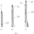
- the first salient point 24 of the needle sleeve is located at the second notch 152 in the bottom of the trajectory surface, and a distance between the main needle and the needle sleeve in this case is minimum.
- the apex angle 21 of the needle sleeve moves upwards, and the distance between the main needle 1 and the needle sleeve 2 becomes larger.
- the apex angle 21 at the head of the needle sleeve first passes over the needle hook for a certain distance, ensuring that the head of the needle sleeve does not come into contact with the tip of the needle hook, and then runs downward to prevent the tip of the needle hook from being deformed.
- the two side sheets of the apex angle of the needle sleeve wrap the needle hook.
- the upper surface of the head of the needle sleeve is flush with the upper surface of the needle hook, i.e., the upper surface of the apex angle forms a smooth circular arc structure with an outer curved surface of the needle hook, and the first salient point 24 of the needle sleeve in this case is located at the first recess 151 of the trajectory surface of the main needle.
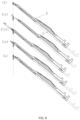
- the needle sleeve 2' on the compound needle B with the loop runs up to a needle turning position (S1); the main needle 1 and the needle sleeve 2 on the compound needle A connected with the loop moves upwards, and the main needle 1 passes through the loop and passes through the hollow structure at the head of the needle sleeve 2', thereby ensuring that the tip of the needle hook of the main needle 1 exceeds the upper surface of the loop (S2); the needle sleeve 2' runs downwards to be disengaged from the loop, and the loop falls onto the main needle 1 of the compound needle A to complete the needle turning action (S3).
- the compound needle of the present embodiment comprises a main needle and a needle sleeve sleeving the main needle.
- a lug boss that protrudes outwards is disposed on the right side of the main needle.
- An inwards-recessed accommodating groove is formed in the front side and the rear side of the lug boss and used for placing the apex of the needle sleeve.
- a salient point is formed on one side, which extends downwards, of the lug boss.
- An uneven trajectory surface is formed on one side, facing the main needle, of the needle sleeve.
- the trajectory surface consists of a plurality of smooth concave surfaces and convex surfaces. The salient point on the main needle props against the trajectory surface on the needle sleeve.
- the main needle may be provided with an upper salient point and a lower salient point which are used for supporting the needle sleeve to slide under a pressed state, to reduce the contact area, thereby reducing the frictional force and facilitate smooth sliding of the needle sleeve in the needle groove.
- the trajectory surface of the needle sleeve is located on one side, facing the main needle, of the intermediate sheet. The trajectory surface is uneven depending on the movement requirements of the needle sleeve, thereby ensuring that the apex angle moves from the needle groove position of the main needle to close the needle hook of the main needle during the movement of the needle sleeve, or continues to move up to the needle turning position.
- Other structures are similar to those of the first embodiment and will not be described again.
Landscapes
- Engineering & Computer Science (AREA)
- Textile Engineering (AREA)
- Knitting Machines (AREA)
Claims (6)
- Aiguille composite pour machine à tricoter plate, comprenant une aiguille principale (1) et un manchon d'aiguille (2) permettant d'emmancher l'aiguille principale (1); l'aiguille principale (1) étant allongée, et un crochet d'aiguille (11) étant disposé au niveau d'une section sommitale de l'aiguille principale (1), une direction dans laquelle le crochet d'aiguille (11) est courbé étant définie comme côté droit, et une direction opposée à la direction dans laquelle le crochet d'aiguille (11) est définie étant définie comme côté gauche ; deux plans de l'aiguille principale (1) perpendiculaires aux côtés droit et gauche étant définis comme face avant et arrière ; l'aiguille principale (1) étant pourvue d'une bosse à ergot (12) qui dépasse vers l'extérieur depuis le côté gauche et est positionnée en dessous du crochet d'aiguille (11) ; une gorge d'insertion en retrait vers l'intérieur (14) étant respectivement formée dans les faces avant et arrière de la bosse à ergot (12) ; le côté gauche de l'aiguille principale (1) étant courbé vers l'intérieur pour former une gorge d'ouverture de passage en retrait (13), une extrémité supérieure du manchon d'aiguille (2) positionnée du côté crochet de l'aiguille principale étant pourvue d'un angle d'apex (21) qui a une structure creuse consistant en deux feuilles latérales aptes à entourer le crochet d'aiguille ; une structure à fente ouverte composée des deux feuilles latérales étant formée dans un côté du manchon d'aiguille (2) tourné vers l'aiguille principale ; un premier point saillant (24) étant formé sur un côté parmi le côté de l'aiguille principale tourné vers le manchon d'aiguille ou le côté du manchon d'aiguille tourné vers l'aiguille principale, et une surface de trajectoire (15) étant formée sur l'autre côté respectif; le premier point saillant coopérant avec la surface de trajectoire de sorte que, lorsque le manchon d'aiguille se déplace, l'angle d'apex se déplace depuis les gorges d'insertion de l'aiguille principale pour fermer le crochet d'aiguille de l'aiguille principale, et les face avant et arrière de l'aiguille principale étant en retrait vers l'intérieur pour former une surface concave (16, 17), et le manchon d'aiguille (2) étant composé d'une feuille intermédiaire et des deux feuilles latérales; l'angle d'apex (21) à l'extrémité supérieure du manchon d'aiguille consistant en les deux feuilles latérales ; caractérisée en ce queun côté de chacune des deux feuilles latérales du manchon d'aiguille (2) tourné vers l'aiguille principale (1) s'étend vers l'extérieur pour former deux bandes de serrage ; et que les bandes de serrage correspondantes sur les deux feuilles latérales forment la première attache (26) et la seconde attache (27) ; le manchon d'aiguille (2) étant serré sur la surface concave de l'aiguille principale à travers la fente ouverte par des bandes de serrage formant des premières attaches (26) et des secondes attaches (27) respectivement ; des sections des feuilles latérales dépassant de la feuille intermédiaire formant deux parois latérales de la structure à fente ouverte, et la section médiane de chacune des deux parois latérales s'étendant entre l'extrémité supérieure respective et l'extrémité inférieure respective étant pourvue d'un intervalle ; chacune parmi la première attache (26) et la seconde attache (27) étant formée à une extrémité supérieure et une extrémité inférieure de chacune des deux parois latérales, chacune des deux feuilles latérales s'étendant vers l'extérieur en direction d'un côté de l'aiguille principale, de sorte que la première attache et la seconde attache sont courbées à l'opposé ; la surface concave (16, 17) sur chacune parmi la face avant et la face arrière de l'aiguille principale (1) consistant en une première surface concave et une seconde surface concave qui sont disposées en sections ; la première attache (26) et la seconde attache (27) étant respectivement fixées sur la première surface concave et la seconde surface concave de l'aiguille principale ; etune feuille élastique (28) apte à être comprimée par la gorge d'aiguille (30) étant disposée sur une face de l'aiguille principale (2) détournée de l'aiguille principale, et ayant une forme de ligne brisée allongée.
- Aiguille composite selon la revendication 1, dans laquelle la surface de trajectoire (15) est formée sur une face de l'aiguille principale (1) tournée vers le manchon d'aiguille ; le premier point saillant (24) est formé sur une face du manchon d'aiguille (2) tournée vers l'aiguille principale ; et le premier point saillant (24) coopère avec la surface de trajectoire (15) de l'aiguille principale de sorte que, lorsque le manchon d'aiguille se déplace le long de l'aiguille principale, l'angle d'apex (21) se déplace depuis la gorge d'insertion de l'aiguille principale pour fermer le crochet d'aiguille de l'aiguille principale.
- Aiguille composite selon la revendication 2, dans laquelle la surface de trajectoire (15) de l'aiguille principale (1) est disposée en dessous de la bosse à ergot (12) et consiste en une pluralité de surfaces concaves et de surfaces convexes lisses, la surface de trajectoire est pourvue d'une première encoche (151) et d'une seconde encoche (152), le premier point saillant (24) sur le manchon d'aiguille (2) se déplace le long de la surface de trajectoire ; lorsque l'angle d'apex du manchon d'aiguille se trouve dans la gorge d'insertion de l'aiguille principale, le premier point saillant est positionné au niveau de la seconde encoche ; lorsque l'angle d'apex du manchon d'aiguille se déplace vers le haut pour fermer le crochet d'aiguille de l'aiguille principale, le premier point saillant se trouve au niveau de la première encoche.
- Aiguille composite selon la revendication 2, dans laquelle un second point saillant (25) est formé sur une face d'une extrémité caudale du manchon d'aiguille (2) tournée vers l'aiguille principale et opposée à l'extrémité supérieure ; et le second point saillant se cale contre et se déplace verticalement le long du côté droit du bas de l'aiguille principale.
- Aiguille composite selon la revendication 1, dans laquelle le premier point saillant (24) est formé sur la face de l'aiguille principale (1) tournée vers le manchon d'aiguille ; la surface de trajectoire est formée sur la face de l'aiguille principale tournée vers l'aiguille principale ; et le premier point saillant (24) avec la surface de trajectoire de sorte que, lorsque le manchon d'aiguille (2) se déplace le long de l'aiguille principale (1), l'angle d'apex se déplace depuis les gorges d'insertion (14) de l'aiguille principale pour fermer le crochet d'aiguille (11) de l'aiguille principale.
- Aiguille composite selon l'une quelconque des revendications 1 à 5, dans laquelle un sens de courbure de l'angle d'apex (21) à l'extrémité supérieure du manchon d'aiguille (2) est cohérent avec un sens de basculement de la pointe du crochet d'aiguille, et l'angle d'apex est courbé vers une face détournée de l'aiguille principale ; la face inférieure de l'angle d'apex du manchon d'aiguille étant en retrait vers l'intérieur pour former une gorge de câblage (22) qui s'étend vers le bas et dépasse vers l'extérieur pour former une extrémité limite (23).
Applications Claiming Priority (1)
| Application Number | Priority Date | Filing Date | Title |
|---|---|---|---|
| CN201910149940.XA CN109750413B (zh) | 2019-02-28 | 2019-02-28 | 一种用于横机的复合针 |
Publications (3)
| Publication Number | Publication Date |
|---|---|
| EP3702505A1 EP3702505A1 (fr) | 2020-09-02 |
| EP3702505B1 true EP3702505B1 (fr) | 2023-08-09 |
| EP3702505C0 EP3702505C0 (fr) | 2023-08-09 |
Family
ID=66408047
Family Applications (1)
| Application Number | Title | Priority Date | Filing Date |
|---|---|---|---|
| EP20159208.6A Active EP3702505B1 (fr) | 2019-02-28 | 2020-02-25 | Aiguille à coulisse pour une machine à tricoter rectiligne |
Country Status (2)
| Country | Link |
|---|---|
| EP (1) | EP3702505B1 (fr) |
| CN (1) | CN109750413B (fr) |
Families Citing this family (3)
| Publication number | Priority date | Publication date | Assignee | Title |
|---|---|---|---|---|
| CN110438655B (zh) * | 2019-08-13 | 2024-04-02 | 宁波慈星股份有限公司 | 一种横机的复合针 |
| CN111286863A (zh) * | 2020-01-14 | 2020-06-16 | 冯加林 | 一种织针 |
| CN111501182B (zh) * | 2020-05-07 | 2024-08-16 | 宁波慈星股份有限公司 | 横机中的碟山 |
Family Cites Families (15)
| Publication number | Priority date | Publication date | Assignee | Title |
|---|---|---|---|---|
| FR1088820A (fr) * | 1952-12-09 | 1955-03-10 | Aiguille pour métiers formant des mailles tels que les tricoteuses et les métiers de bonneterie | |
| JP3554094B2 (ja) * | 1995-12-12 | 2004-08-11 | 株式会社島精機製作所 | 目移し機能を有する複合針 |
| JP2946323B2 (ja) * | 1997-05-01 | 1999-09-06 | 株式会社島精機製作所 | 横編機の複合針 |
| FR2821093B1 (fr) * | 2001-02-20 | 2003-05-09 | Steiger S A C Atel Const | Aiguille a coulisse pour machine a tricoter |
| DE10152856C1 (de) * | 2001-03-14 | 2003-04-24 | Ulrich Hofmann | Vorrichtung zum maschinellen Maschenbilden |
| JP4348286B2 (ja) * | 2004-12-09 | 2009-10-21 | 株式会社島精機製作所 | 横編機 |
| JP5057674B2 (ja) * | 2006-02-28 | 2012-10-24 | 株式会社島精機製作所 | 横編機の編出し装置 |
| JP5525344B2 (ja) * | 2010-06-18 | 2014-06-18 | 株式会社島精機製作所 | 横編機の複合針 |
| JP5732316B2 (ja) * | 2010-06-18 | 2015-06-10 | 株式会社島精機製作所 | 横編機の複合針 |
| JP5632277B2 (ja) * | 2010-12-22 | 2014-11-26 | 株式会社島精機製作所 | 横編機の複合針 |
| CN103334223A (zh) * | 2013-07-04 | 2013-10-02 | 宁波慈星股份有限公司 | 一种用于横编机的织针 |
| CN203333962U (zh) * | 2013-07-04 | 2013-12-11 | 宁波慈星股份有限公司 | 一种用于横编机的织针 |
| CN104928841A (zh) * | 2015-07-07 | 2015-09-23 | 汕头市连兴实业有限公司 | 一种新型复合针 |
| CN108035063A (zh) * | 2018-01-17 | 2018-05-15 | 宁波慈星股份有限公司 | 一种用于横编机的复合针 |
| CN209759718U (zh) * | 2019-02-28 | 2019-12-10 | 宁波慈星股份有限公司 | 一种用于横机的复合针 |
-
2019
- 2019-02-28 CN CN201910149940.XA patent/CN109750413B/zh active Active
-
2020
- 2020-02-25 EP EP20159208.6A patent/EP3702505B1/fr active Active
Also Published As
| Publication number | Publication date |
|---|---|
| EP3702505C0 (fr) | 2023-08-09 |
| EP3702505A1 (fr) | 2020-09-02 |
| CN109750413A (zh) | 2019-05-14 |
| CN109750413B (zh) | 2023-09-29 |
Similar Documents
| Publication | Publication Date | Title |
|---|---|---|
| EP3702506A1 (fr) | Aiguille à coulisse pour une machine à tricoter rectiligne | |
| EP3702505B1 (fr) | Aiguille à coulisse pour une machine à tricoter rectiligne | |
| JP5608616B2 (ja) | 磨耗低減を示す編みシステム用シンカー | |
| US8141394B2 (en) | Knitting tool arrangement and knitting tool | |
| US4646542A (en) | Device for the passing of the stitch from a needle for the forming of plain knitting to a needle for the forming of purl knitting and vice versa, in a knitting machine and the like | |
| US6422045B1 (en) | Compound needle of knitting machine | |
| CN100436688C (zh) | 复合针 | |
| KR102659773B1 (ko) | 편직 바늘 | |
| EP3779009A1 (fr) | Aiguille à coulisse de machine à tricoter rectiligne | |
| WO2008018185A1 (fr) | Platine mobile et métier à mailles cueillies | |
| TWI896827B (zh) | 針體、複合針組件及經紗編織機 | |
| CN222294368U (zh) | 针织机复合针的主针结构 | |
| CN209759719U (zh) | 一种横机中的复合针 | |
| CN209759718U (zh) | 一种用于横机的复合针 | |
| KR20060133017A (ko) | 횡편기의 가동 싱커 장치 및 싱커 | |
| JPH10266049A (ja) | 編目を形成する繊維機械のための舌針 | |
| JP7463343B2 (ja) | ラッチニードル | |
| JP4408803B2 (ja) | 可動シンカおよび可動シンカを備える横編機 | |
| CN222294366U (zh) | 一种针织机复合针 | |
| CN223866897U (zh) | 一种电脑提花机的提花片 | |
| US2872799A (en) | Knitting machinery | |
| CN118292179B (zh) | 转移针 | |
| JPS62206069A (ja) | 編機用の複合針 | |
| CN111501181A (zh) | 嘴口可变的横编机结构 | |
| CN109056178A (zh) | 横编机中的压片 |
Legal Events
| Date | Code | Title | Description |
|---|---|---|---|
| PUAI | Public reference made under article 153(3) epc to a published international application that has entered the european phase |
Free format text: ORIGINAL CODE: 0009012 |
|
| STAA | Information on the status of an ep patent application or granted ep patent |
Free format text: STATUS: THE APPLICATION HAS BEEN PUBLISHED |
|
| AK | Designated contracting states |
Kind code of ref document: A1 Designated state(s): AL AT BE BG CH CY CZ DE DK EE ES FI FR GB GR HR HU IE IS IT LI LT LU LV MC MK MT NL NO PL PT RO RS SE SI SK SM TR |
|
| AX | Request for extension of the european patent |
Extension state: BA ME |
|
| STAA | Information on the status of an ep patent application or granted ep patent |
Free format text: STATUS: REQUEST FOR EXAMINATION WAS MADE |
|
| 17P | Request for examination filed |
Effective date: 20210222 |
|
| RBV | Designated contracting states (corrected) |
Designated state(s): AL AT BE BG CH CY CZ DE DK EE ES FI FR GB GR HR HU IE IS IT LI LT LU LV MC MK MT NL NO PL PT RO RS SE SI SK SM TR |
|
| STAA | Information on the status of an ep patent application or granted ep patent |
Free format text: STATUS: EXAMINATION IS IN PROGRESS |
|
| 17Q | First examination report despatched |
Effective date: 20220316 |
|
| GRAP | Despatch of communication of intention to grant a patent |
Free format text: ORIGINAL CODE: EPIDOSNIGR1 |
|
| STAA | Information on the status of an ep patent application or granted ep patent |
Free format text: STATUS: GRANT OF PATENT IS INTENDED |
|
| INTG | Intention to grant announced |
Effective date: 20230530 |
|
| GRAS | Grant fee paid |
Free format text: ORIGINAL CODE: EPIDOSNIGR3 |
|
| GRAA | (expected) grant |
Free format text: ORIGINAL CODE: 0009210 |
|
| STAA | Information on the status of an ep patent application or granted ep patent |
Free format text: STATUS: THE PATENT HAS BEEN GRANTED |
|
| AK | Designated contracting states |
Kind code of ref document: B1 Designated state(s): AL AT BE BG CH CY CZ DE DK EE ES FI FR GB GR HR HU IE IS IT LI LT LU LV MC MK MT NL NO PL PT RO RS SE SI SK SM TR |
|
| REG | Reference to a national code |
Ref country code: GB Ref legal event code: FG4D |
|
| REG | Reference to a national code |
Ref country code: CH Ref legal event code: EP |
|
| REG | Reference to a national code |
Ref country code: IE Ref legal event code: FG4D |
|
| REG | Reference to a national code |
Ref country code: DE Ref legal event code: R096 Ref document number: 602020015216 Country of ref document: DE |
|
| U01 | Request for unitary effect filed |
Effective date: 20230817 |
|
| U07 | Unitary effect registered |
Designated state(s): AT BE BG DE DK EE FI FR IT LT LU LV MT NL PT SE SI Effective date: 20230822 |
|
| U20 | Renewal fee for the european patent with unitary effect paid |
Year of fee payment: 5 Effective date: 20231204 |
|
| PG25 | Lapsed in a contracting state [announced via postgrant information from national office to epo] |
Ref country code: GR Free format text: LAPSE BECAUSE OF FAILURE TO SUBMIT A TRANSLATION OF THE DESCRIPTION OR TO PAY THE FEE WITHIN THE PRESCRIBED TIME-LIMIT Effective date: 20231110 |
|
| PG25 | Lapsed in a contracting state [announced via postgrant information from national office to epo] |
Ref country code: IS Free format text: LAPSE BECAUSE OF FAILURE TO SUBMIT A TRANSLATION OF THE DESCRIPTION OR TO PAY THE FEE WITHIN THE PRESCRIBED TIME-LIMIT Effective date: 20231209 |
|
| PG25 | Lapsed in a contracting state [announced via postgrant information from national office to epo] |
Ref country code: RS Free format text: LAPSE BECAUSE OF FAILURE TO SUBMIT A TRANSLATION OF THE DESCRIPTION OR TO PAY THE FEE WITHIN THE PRESCRIBED TIME-LIMIT Effective date: 20230809 Ref country code: NO Free format text: LAPSE BECAUSE OF FAILURE TO SUBMIT A TRANSLATION OF THE DESCRIPTION OR TO PAY THE FEE WITHIN THE PRESCRIBED TIME-LIMIT Effective date: 20231109 Ref country code: IS Free format text: LAPSE BECAUSE OF FAILURE TO SUBMIT A TRANSLATION OF THE DESCRIPTION OR TO PAY THE FEE WITHIN THE PRESCRIBED TIME-LIMIT Effective date: 20231209 Ref country code: HR Free format text: LAPSE BECAUSE OF FAILURE TO SUBMIT A TRANSLATION OF THE DESCRIPTION OR TO PAY THE FEE WITHIN THE PRESCRIBED TIME-LIMIT Effective date: 20230809 Ref country code: GR Free format text: LAPSE BECAUSE OF FAILURE TO SUBMIT A TRANSLATION OF THE DESCRIPTION OR TO PAY THE FEE WITHIN THE PRESCRIBED TIME-LIMIT Effective date: 20231110 |
|
| PG25 | Lapsed in a contracting state [announced via postgrant information from national office to epo] |
Ref country code: PL Free format text: LAPSE BECAUSE OF FAILURE TO SUBMIT A TRANSLATION OF THE DESCRIPTION OR TO PAY THE FEE WITHIN THE PRESCRIBED TIME-LIMIT Effective date: 20230809 |
|
| PG25 | Lapsed in a contracting state [announced via postgrant information from national office to epo] |
Ref country code: ES Free format text: LAPSE BECAUSE OF FAILURE TO SUBMIT A TRANSLATION OF THE DESCRIPTION OR TO PAY THE FEE WITHIN THE PRESCRIBED TIME-LIMIT Effective date: 20230809 |
|
| PG25 | Lapsed in a contracting state [announced via postgrant information from national office to epo] |
Ref country code: SM Free format text: LAPSE BECAUSE OF FAILURE TO SUBMIT A TRANSLATION OF THE DESCRIPTION OR TO PAY THE FEE WITHIN THE PRESCRIBED TIME-LIMIT Effective date: 20230809 Ref country code: RO Free format text: LAPSE BECAUSE OF FAILURE TO SUBMIT A TRANSLATION OF THE DESCRIPTION OR TO PAY THE FEE WITHIN THE PRESCRIBED TIME-LIMIT Effective date: 20230809 Ref country code: ES Free format text: LAPSE BECAUSE OF FAILURE TO SUBMIT A TRANSLATION OF THE DESCRIPTION OR TO PAY THE FEE WITHIN THE PRESCRIBED TIME-LIMIT Effective date: 20230809 Ref country code: CZ Free format text: LAPSE BECAUSE OF FAILURE TO SUBMIT A TRANSLATION OF THE DESCRIPTION OR TO PAY THE FEE WITHIN THE PRESCRIBED TIME-LIMIT Effective date: 20230809 Ref country code: SK Free format text: LAPSE BECAUSE OF FAILURE TO SUBMIT A TRANSLATION OF THE DESCRIPTION OR TO PAY THE FEE WITHIN THE PRESCRIBED TIME-LIMIT Effective date: 20230809 |
|
| REG | Reference to a national code |
Ref country code: DE Ref legal event code: R097 Ref document number: 602020015216 Country of ref document: DE |
|
| PLBE | No opposition filed within time limit |
Free format text: ORIGINAL CODE: 0009261 |
|
| STAA | Information on the status of an ep patent application or granted ep patent |
Free format text: STATUS: NO OPPOSITION FILED WITHIN TIME LIMIT |
|
| 26N | No opposition filed |
Effective date: 20240513 |
|
| PG25 | Lapsed in a contracting state [announced via postgrant information from national office to epo] |
Ref country code: MC Free format text: LAPSE BECAUSE OF FAILURE TO SUBMIT A TRANSLATION OF THE DESCRIPTION OR TO PAY THE FEE WITHIN THE PRESCRIBED TIME-LIMIT Effective date: 20230809 |
|
| REG | Reference to a national code |
Ref country code: CH Ref legal event code: PL |
|
| PG25 | Lapsed in a contracting state [announced via postgrant information from national office to epo] |
Ref country code: CH Free format text: LAPSE BECAUSE OF NON-PAYMENT OF DUE FEES Effective date: 20240229 |
|
| GBPC | Gb: european patent ceased through non-payment of renewal fee |
Effective date: 20240225 |
|
| PG25 | Lapsed in a contracting state [announced via postgrant information from national office to epo] |
Ref country code: CH Free format text: LAPSE BECAUSE OF NON-PAYMENT OF DUE FEES Effective date: 20240229 |
|
| PG25 | Lapsed in a contracting state [announced via postgrant information from national office to epo] |
Ref country code: GB Free format text: LAPSE BECAUSE OF NON-PAYMENT OF DUE FEES Effective date: 20240225 |
|
| PG25 | Lapsed in a contracting state [announced via postgrant information from national office to epo] |
Ref country code: IE Free format text: LAPSE BECAUSE OF NON-PAYMENT OF DUE FEES Effective date: 20240225 |
|
| PG25 | Lapsed in a contracting state [announced via postgrant information from national office to epo] |
Ref country code: IE Free format text: LAPSE BECAUSE OF NON-PAYMENT OF DUE FEES Effective date: 20240225 Ref country code: GB Free format text: LAPSE BECAUSE OF NON-PAYMENT OF DUE FEES Effective date: 20240225 |
|
| U20 | Renewal fee for the european patent with unitary effect paid |
Year of fee payment: 6 Effective date: 20241231 |
|
| PG25 | Lapsed in a contracting state [announced via postgrant information from national office to epo] |
Ref country code: CY Free format text: LAPSE BECAUSE OF FAILURE TO SUBMIT A TRANSLATION OF THE DESCRIPTION OR TO PAY THE FEE WITHIN THE PRESCRIBED TIME-LIMIT; INVALID AB INITIO Effective date: 20200225 |
|
| PG25 | Lapsed in a contracting state [announced via postgrant information from national office to epo] |
Ref country code: HU Free format text: LAPSE BECAUSE OF FAILURE TO SUBMIT A TRANSLATION OF THE DESCRIPTION OR TO PAY THE FEE WITHIN THE PRESCRIBED TIME-LIMIT; INVALID AB INITIO Effective date: 20200225 |
|
| PG25 | Lapsed in a contracting state [announced via postgrant information from national office to epo] |
Ref country code: TR Free format text: LAPSE BECAUSE OF FAILURE TO SUBMIT A TRANSLATION OF THE DESCRIPTION OR TO PAY THE FEE WITHIN THE PRESCRIBED TIME-LIMIT Effective date: 20230809 |
|
| U20 | Renewal fee for the european patent with unitary effect paid |
Year of fee payment: 7 Effective date: 20251204 |