EP3702531A1 - Profilé de remplissage de joint - Google Patents
Profilé de remplissage de joint Download PDFInfo
- Publication number
- EP3702531A1 EP3702531A1 EP20155300.5A EP20155300A EP3702531A1 EP 3702531 A1 EP3702531 A1 EP 3702531A1 EP 20155300 A EP20155300 A EP 20155300A EP 3702531 A1 EP3702531 A1 EP 3702531A1
- Authority
- EP
- European Patent Office
- Prior art keywords
- joint
- profile body
- separating material
- joint filling
- profile
- Prior art date
- Legal status (The legal status is an assumption and is not a legal conclusion. Google has not performed a legal analysis and makes no representation as to the accuracy of the status listed.)
- Granted
Links
Images


Classifications
-
- E—FIXED CONSTRUCTIONS
- E04—BUILDING
- E04B—GENERAL BUILDING CONSTRUCTIONS; WALLS, e.g. PARTITIONS; ROOFS; FLOORS; CEILINGS; INSULATION OR OTHER PROTECTION OF BUILDINGS
- E04B1/00—Constructions in general; Structures which are not restricted either to walls, e.g. partitions, or floors or ceilings or roofs
- E04B1/62—Insulation or other protection; Elements or use of specified material therefor
- E04B1/66—Sealings
- E04B1/68—Sealings of joints, e.g. expansion joints
- E04B1/6803—Joint covers
- E04B1/6804—Joint covers specially adapted for floor parts
-
- E—FIXED CONSTRUCTIONS
- E01—CONSTRUCTION OF ROADS, RAILWAYS, OR BRIDGES
- E01C—CONSTRUCTION OF, OR SURFACES FOR, ROADS, SPORTS GROUNDS, OR THE LIKE; MACHINES OR AUXILIARY TOOLS FOR CONSTRUCTION OR REPAIR
- E01C11/00—Details of pavings
- E01C11/02—Arrangement or construction of joints; Methods of making joints; Packing for joints
-
- E—FIXED CONSTRUCTIONS
- E01—CONSTRUCTION OF ROADS, RAILWAYS, OR BRIDGES
- E01C—CONSTRUCTION OF, OR SURFACES FOR, ROADS, SPORTS GROUNDS, OR THE LIKE; MACHINES OR AUXILIARY TOOLS FOR CONSTRUCTION OR REPAIR
- E01C11/00—Details of pavings
- E01C11/02—Arrangement or construction of joints; Methods of making joints; Packing for joints
- E01C11/04—Arrangement or construction of joints; Methods of making joints; Packing for joints for cement concrete paving
-
- E—FIXED CONSTRUCTIONS
- E01—CONSTRUCTION OF ROADS, RAILWAYS, OR BRIDGES
- E01D—CONSTRUCTION OF BRIDGES, ELEVATED ROADWAYS OR VIADUCTS; ASSEMBLY OF BRIDGES
- E01D19/00—Structural or constructional details of bridges
- E01D19/06—Arrangement, construction or bridging of expansion joints
-
- E—FIXED CONSTRUCTIONS
- E01—CONSTRUCTION OF ROADS, RAILWAYS, OR BRIDGES
- E01D—CONSTRUCTION OF BRIDGES, ELEVATED ROADWAYS OR VIADUCTS; ASSEMBLY OF BRIDGES
- E01D19/00—Structural or constructional details of bridges
- E01D19/06—Arrangement, construction or bridging of expansion joints
- E01D19/065—Joints having sliding plates
-
- E—FIXED CONSTRUCTIONS
- E04—BUILDING
- E04B—GENERAL BUILDING CONSTRUCTIONS; WALLS, e.g. PARTITIONS; ROOFS; FLOORS; CEILINGS; INSULATION OR OTHER PROTECTION OF BUILDINGS
- E04B1/00—Constructions in general; Structures which are not restricted either to walls, e.g. partitions, or floors or ceilings or roofs
- E04B1/62—Insulation or other protection; Elements or use of specified material therefor
- E04B1/66—Sealings
- E04B1/68—Sealings of joints, e.g. expansion joints
- E04B1/6801—Fillings therefor
-
- E—FIXED CONSTRUCTIONS
- E04—BUILDING
- E04F—FINISHING WORK ON BUILDINGS, e.g. STAIRS, FLOORS
- E04F15/00—Flooring
- E04F15/02—Flooring or floor layers composed of a number of similar elements
- E04F15/02005—Construction of joints, e.g. dividing strips
- E04F15/02011—Construction of joints, e.g. dividing strips with joint fillings integrated in the flooring elements
-
- E—FIXED CONSTRUCTIONS
- E04—BUILDING
- E04F—FINISHING WORK ON BUILDINGS, e.g. STAIRS, FLOORS
- E04F15/00—Flooring
- E04F15/02—Flooring or floor layers composed of a number of similar elements
- E04F15/02005—Construction of joints, e.g. dividing strips
- E04F15/02016—Construction of joints, e.g. dividing strips with sealing elements between flooring elements
-
- E—FIXED CONSTRUCTIONS
- E04—BUILDING
- E04F—FINISHING WORK ON BUILDINGS, e.g. STAIRS, FLOORS
- E04F15/00—Flooring
- E04F15/02—Flooring or floor layers composed of a number of similar elements
- E04F15/02005—Construction of joints, e.g. dividing strips
- E04F15/02033—Joints with beveled or recessed upper edges
-
- E—FIXED CONSTRUCTIONS
- E04—BUILDING
- E04F—FINISHING WORK ON BUILDINGS, e.g. STAIRS, FLOORS
- E04F15/00—Flooring
- E04F15/12—Flooring or floor layers made of masses in situ, e.g. seamless magnesite floors, terrazzo gypsum floors
- E04F15/14—Construction of joints, e.g. dividing strips
-
- E—FIXED CONSTRUCTIONS
- E04—BUILDING
- E04F—FINISHING WORK ON BUILDINGS, e.g. STAIRS, FLOORS
- E04F15/00—Flooring
- E04F15/12—Flooring or floor layers made of masses in situ, e.g. seamless magnesite floors, terrazzo gypsum floors
- E04F15/14—Construction of joints, e.g. dividing strips
- E04F15/142—Dividing strips or boundary strips
Definitions
- the invention relates to a joint filling profile for forming a joint seal between floor panels, with a vertical leg projecting into the joint and a profile body formed from a joint sealing compound and lying in a joint widening.
- Joint filling profiles for forming a joint seal are well known per se from the prior art.
- joint filling typically, the joint provided between two floor panels is sealed by means of a so-called joint filling. This can be done in a simple manner by filling the joint with a joint sealing compound.
- joint filling profiles designed in such a simple manner have a disadvantageous shortage of service life, in particular when they are exposed to corresponding loads, as is often the case in industrial applications.
- the DE 100 02 866 B4 a construction has been proposed, which is designed according to the free upper facing edges of adjacent floor panels a substantially horizontally extending joint widening, the joint being filled with joint sealing compound flush with the surface up to the joint widening.
- vertical depressions so-called anchoring cuts, are formed in the end edge area of the joint widening, in which the profile body formed from joint sealing compound engages.
- each of the floor panels provides an area adjacent to the vertical leg of the joint filling profile which is chemically and / or mechanically equipped so that the joint sealing compound introduced into the joint and the joint widening does not enter into a direct connection with the floor panel in this area.
- joint filling profile has increased elasticity without the risk of it becoming detached from the subsurface, since in the areas in which there is no direct connection between the joint sealing compound on the one hand and the floor slabs on the other, expansion of the material forming the joint sealing compound is permitted is because in these areas only the material is stretched without being hindered by sticking to the substrate.
- joint filling profiles are capable of EP 2 098 651 A2 to withstand higher mechanical and / or thermal loads, and this with a significantly reduced risk of unwanted detachment from the substrate.
- a joint formation is known, according to which a joint remains unfilled, for which purpose a reinforcing element is provided which bridges the joint.
- an adhesive tape is preferably provided, which is arranged in the edge regions of the reinforcement element.
- a cover element can also be provided, for example in the form of an adhesive tape.
- a method for preserving a soil cover layer is known. Accordingly, a floor is equipped with a top layer, the top layer having a binding layer made of a slightly viscous, flowable bitumen mortar.
- the bitumen mortar contains a mixture of a cationic bitumen emulsion and a demulsifier with a mineral granulate in the form of a powdery filler.
- the AT 375 984 B discloses a roadway transition for bridging joints present in the roadway substructure, which has a sealing membrane to cover the joint.
- a cover that absorbs traffic loads is provided, which is located above the sealing membrane.
- the WO 2007/053119 A1 relates to a method for applying a coating medium to structural elements, a stress redistribution structure being used to cover and bridge discontinuities within the structural elements.
- the coating medium is above the Stress redistribution structure applied to this in such a way that the coating medium comes into contact with the surfaces of the structural elements outside the stress redistribution structure.
- the invention is therefore based on the object of specifying a joint filling profile which eliminates the aforementioned disadvantages.
- the invention proposes a joint filling profile for forming a joint seal between floor panels, with a vertical leg protruding into the joint and a profile body formed from a joint sealing compound and lying in a joint widening, the vertical leg and the profile body being separated from one another with the interposition of a separation material , with at least one second separating material between the vertical limb and the profile body and / or with at least one reinforcing mat being arranged within the profile body, the second separating material and / or the reinforcing mat being arranged at least partially overlapping with the first separating material.
- each of the embodiments claimed according to the invention taken individually and in synergetic combination with one another, is suitable for eliminating the disadvantages prevailing in the prior art.
- the double-layer arrangement of two separating materials which are preferably formed from metal foils, in particular from aluminum foils, enables further decoupling of the profile body and the vertical web compared to the prior art. This is in particular because the first separating material only has contact with the vertical web, but not with the profile body. On the other hand, the second separating material only has contact with the profile body, but not with the vertical web. In the case of stretching movements, the two separating materials, especially in the case of metal foils, can slide over one another completely freely.
- the second separating material In contrast to the prior art, in which only a separating material is provided and in which adhesion on both sides can take place, there are no consequences for the adhesion of joint sealing compound to the foils.
- the second separating material As an alternative material for the second separating material, besides being formed as a metal foil, it has also proven to be effective in the form of a fleece. This is because, on the one hand, it is impermeable to the joint sealing compound and, on the other hand, is able to slide over the first separating material, which is designed as a metal foil, in particular aluminum foil, with particularly low frictional resistance.
- the two Separating materials can consequently be formed from the same material or from different materials.
- the embodiment according to the invention comprising the at least one reinforcement mat advantageously prevents the disadvantageous crack formation that occurs in the prior art in the sections not covered by the first separating material. Material stresses occurring in these sections between the base plates and the profile body are completely absorbed by the at least one reinforcement mat.
- the profile body preferably has at least one first section adjacent to the vertical web. A second section of the profile body adjoins the first section.
- the separating material is arranged exclusively between the vertical web and the profile body and in the area of the at least one first section.
- the second separating material is preferably arranged in the direction of the profile body above the first separating material and likewise exclusively between the vertical web and the profile body and in the region of the at least one first section.
- the profile body has two first sections, which are formed opposite one another in cross section, adjacent to the vertical web on both sides.
- a second section of the profile body preferably adjoins a first section.
- the profile body can be designed to be axially symmetrical.
- the reinforcement mat it is preferred that it is formed in a grid-like manner from longitudinal and transverse struts. As a result, the forces acting at the nodes of the respective struts are distributed over the entire grid. It is also preferred that continuous openings are formed between the longitudinal and transverse struts for the joint sealing compound. This ensures that the joint sealing compound of the profile body is in contact with the respective floor panels in the second sections. A separate separation between the profile body and floor panels, as with the EP 2 098 651 A1 was proposed, is no longer necessary due to the design according to the invention, since this function is also fully fulfilled by the separating material.
- the reinforcement mat according to the invention serves to absorb the stresses going beyond this.
- the edge of the one extending beyond the separating material Form the end of the reinforcement mat with a contour that changes in the longitudinal direction.
- a variable contour is in particular a wave-shaped contour, a zigzag contour or a fringe-like contour.
- alternating longitudinal struts and transverse struts form the respective end of the reinforcement mat.
- the fringe-like contour has proven to be particularly advantageous.
- the reinforcement mat can basically be formed from any material that is suitable for absorbing the stresses that arise. Mats made of metal, in particular metal wire, or plastic are particularly preferred.
- the reinforcement mats are particularly preferably made of plastic. This is because, in addition to its known material properties, plastic interacts particularly well with the joint sealing compound, which is preferably formed from an elastic polymer resin. In synergy, this leads to particularly good voltage conduction between the profile body and the reinforcement mat.
- a further reinforcement mat is provided.
- the first reinforcement mat extends over the first and second sections running on one side of the joint.
- the second reinforcement mat extends over the first and second sections running on the other side of the joint. This prevents the formation of cracks over the entire profile body.
- the reinforcement mats are arranged leaving a gap that is aligned with the joint 2 in the vertical direction thereof.
- the stress absorption is adapted to the axially symmetrical design of the joint filling profile. Both areas separated from one another by the mirror axis thus have a separate reinforcement mat. Different tensions in the respective areas can be absorbed individually.
- the joint filling profile formed from the vertical leg and the profile body is not formed in one piece. Rather, it is provided according to the invention to separate the vertical limb from the profile body, specifically in that the vertical limb and the profile body are separated from one another with the interposition of a separating material. It is provided that the joint filling profile thereby to train that the joint is first filled so that the vertical leg of the later joint filling profile is created.
- the vertical leg formed in this way is then equipped with a separating material on its upper side facing the widened joint.
- a separating material on its upper side facing the widened joint.
- This can be done mechanically or chemically, with the formation of a mechanical separation by the introduction of an intermediate layer being preferred.
- a metal foil, in particular an aluminum foil, for example, can serve as the mechanical separating layer, which has the advantage that there are no thermal restrictions with regard to the use and processing of corresponding joint sealing compounds.
- the profile body is then formed from a casting compound, the profile body being separated from the vertical limb due to the previously applied separating material. There is therefore no direct connection between the vertical leg and the profile body after the joint filling profile has been formed.
- the separation according to the invention of the vertical limb and the profile body has the essential advantage that undesirable crack formation is avoided even in the transition area between the vertical limb and the profile body. Because, due to the lack of one-piece design, different material thicknesses are not formed, so that different expansion behavior due to different material thicknesses is prevented. Unwanted detachment phenomena, in particular flank tears, can thus be avoided even more effectively, thus resulting in an increased service life.
- the profile body rests in a connection-free manner in a first section adjacent to the joint with the interposition of a separating material on the associated base plate.
- This configuration advantageously allows the joint filling profile to stretch to compensate for mechanical and / or thermal loads to be able to afford, whereby due to the lack of direct connection between the profile body substrate in the above-described area there is no risk of tearing and / or detachment.
- the lack of one-piece design of the profile body and vertical leg comes into play, since the profile body can expand both horizontally and vertically independently of the vertical leg, so the possibility of expansion of the profile body is not impaired by the vertical leg.
- the lens effects that occur in a disadvantageous manner in constructions known from the prior art, that is to say constrictions caused by stretching, can thus be reduced or even prevented.
- a multiplicity of reinforcements is embedded in the profile body, which reinforcements are arranged one behind the other in the longitudinal direction of the joint.
- the purpose of the reinforcements is to prevent the profile body from buckling or bulging in the area where there is no direct connection to the subsurface in the event of expansion.
- the reinforcement therefore ensures that the profile body, in spite of the above-described elasticity, terminates essentially plane-parallel with the adjacent floor panels even in the event of a load.
- a reinforcement has a guide body on the one hand and a reinforcing element on the other hand, the reinforcing element being designed to be displaceable relative to the guide body.
- the guide body receives the reinforcement element, so that there is no direct connection between the joint sealing compound of the profile body and the reinforcement element.
- the reinforcement element therefore does not hinder the elasticity of the profile body. Rather, due to the relative displaceability of the reinforcement element with respect to the guide body, it is possible for the reinforcement element to join in with the movements of the profile body.
- the guide body is also extensible, so that it does not prevent the profile body from stretching.
- the guide body is a sleeve
- the reinforcing element can be, for example, a rod, in particular a metal rod.
- the rod is removed from the sleeve Is received longitudinally displaceably, the sleeve having a longitudinal extent exceeding the longitudinal extent of the rod. This ensures that in the event of the profile body being stretched, the rod can move accordingly within the sleeve and is not restricted in its movement, for example, by the sleeve.
- the rod Due to the fact that the sleeve is made longer in the longitudinal direction than the rod, the rod can move inside the sleeve in the event of expansion, so that the expansion movement of the profile body is not blocked by the rod serving as a reinforcing element.
- the reinforcement mats in the second sections rest on the floor plates with a spacer between them. It is also preferred that the reinforcement mats each rest on the separating material in the first sections. This ensures that the reinforcement mats are horizontal, i.e. are aligned parallel to the floor slabs in the joint widening. This achieves a particularly homogeneous stress absorption on the part of the reinforcement mats.
- the reinforcement rests on the reinforcement mats.
- it is supported by the interposition of the reinforcement mats on the spacers and can thus be precisely positioned in the widened joint.
- the reinforcement extends into the second sections, but the connecting mats in the second sections extend beyond the reinforcement.
- the profile body is designed to be axially symmetrical and has two first sections adjacent to the joint, each of which is followed by a second section. There is no direct connection between the profile body and the substrate in the area of the joint and the first two sections. Such a direct connection is formed in the outer second sections.
- the separating material extends in the area of the joint and the two first sections adjacent thereto.
- a continuous area is created in this way, which, starting from the first section of the first floor slab, extends over the joint to the first section of the second base plate extends, in which no direct connection of the profile body is formed with the ground.
- the vertical limb and / or the profile body are temperature-resistant at least in sections up to a temperature of 60 ° C, preferably up to a temperature of 70 ° C, more preferably up to a temperature of 80 ° C is / are trained.
- the joint filling profile is designed to be temperature-resistant, at least in sections.
- the joint filling profile is therefore also suitable for installation in areas that are intended to be exposed to elevated temperatures.
- the casting compound forming the vertical leg and / or the profile body is made from a material that is thermostable up to 60 ° C., preferably from one to 70 ° C., even more preferably from a material that is thermally stable up to 80 ° C. is / are formed.
- a thermally stable plastic material is preferably used in this connection, which is introduced into the joint and / or the widened joint in the liquid state and, after it has hardened, is thermally stable up to the temperatures mentioned.
- the vertical limb and / or the profile body are formed from a non-thermally stable material and a coating that covers the profile body on the upper side is provided, which is formed to be thermostable up to the temperatures mentioned. It can also be provided that the vertical limb and the profile body are made from different materials, for example the vertical limb from a non-thermally stable material and the profile body from a thermally stable material.
- granules made of a thermally stable material are added to the casting compound.
- Such granules can be stone materials and / or graphite, for example.
- the Vertical leg and / or the profile body forming potting compound has particles that change their color as a result of physical and / or chemical influences.
- the change in color of the particles is used in an advantageous manner to enable the user to visually check the joint filling profile designed according to the invention.
- Physical and / or chemical influencing factors that can lead to a change in color of the particles added to the potting compound are, for example, mechanical pressurization, aging processes, the effects of chemical substances such as acid and / or the like. It is particularly preferred to add particles to the potting compound which change their color over time, that is to say over the service life of the joint filling profile according to the invention. In this way, the user can easily determine that the manufacturer's guaranteed service life of the joint filling profile has been reached, which is why it must be replaced to ensure functional reliability.
- a change in color as a result of excessive mechanical stress is also advantageous, because, in particular, excessive pressure stress can lead to irreversible deformation of the joint filling profile.
- the actually desired functional reliability can then possibly no longer be given, which is visually indicated to the user by a color change in the joint filling profile.
- chemical substances These too can lead to damage to the joint filling profile, which is why it is advantageous that a user can be shown by means of a change in color that the joint filling profile has been exposed to corresponding chemical substances, such as acids.
- a signal line is embedded in the profile body and / or the vertical leg.
- a signal line can be an optical waveguide or a current-carrying conductor.
- Such a signal line proves to be advantageous for several reasons.
- it can be used as a means of counting crossings. This can be done, for example, in that a signal is permanently present on the signal line which changes as a result of a pressure load, that is, in the event of a drive over. This change in signal is detected by means of a corresponding receiving unit.
- the number of crossings can be determined, preferably providing that when a predefinable number of crossings is reached, a display indicating the Informs the user that a number of passes guaranteed by the manufacturer, for example, has been reached.
- the signal line can advantageously also be used as a crack warning device. Because in the event of crack formation, the signal line is exposed and / or the same is destroyed. This can be detected and indicated to the user accordingly.
- a plurality of signal lines are preferably used, possibly also in the form of a signal line mat. Such a mat can at the same time also serve as a separating material in the sense already explained above.
- a moisture sensor is provided.
- a moisture sensor can be embedded in the sealing compound of the joint filling profile and / or introduced into the joint and / or the joint widening before the vertical leg and / or the profile body are formed.
- the moisture sensor is used in particular to detect water that has penetrated the joint filling profile, so that in the event of detection a corresponding output can be made to the user.
- the joint filling profile designed according to the invention is designed to be watertight and also lies watertight against the associated floor panels. In the event that the moisture sensor hits, this is equivalent to the fact that the joint filling profile is destroyed at least in sections and / or has crack formation through which water has penetrated.
- the moisture sensor is therefore used to detect any damage to the joint filling profile at an early stage.
- a light strip embedded in the joint filling profile is provided.
- a light strip is used in particular in emergency situations to provide guidance and / or to mark escape routes.
- it is preferably provided to connect the light strip to a corresponding emergency system in terms of communication technology, so that the light strip is actually only put into operation in the event of an emergency.
- the joint filling profile is characterized by an embedded, fire-retardant, heat-insulating and / or, under the action of heat, an agent, for example an active ingredient that releases a coolant.
- a fire-retardant active ingredient can be formed, for example, by suitable mortar, stone materials and / or the like. Mineral fibers, rock wool or the like can be provided as heat-insulating agents.
- An active ingredient that releases an agent under the action of heat can in particular be a material that foams under the action of heat or a hydrate that releases water under the influence of heat. Alternatively, an active ingredient can also be provided which swells under the influence of heat.
- an active ingredient of the aforementioned type is provided in particular for those joint filling profiles that are formed below room closures, such as doors or gates.
- those active ingredients are to be preferred that swell under the action of heat, because this ensures that the gap provided between the room closure and the joint filling profile swells up in the intended use. This not only provides protection against flashover, but also against unwanted smoke spreading.
- An active ingredient that swells under the action of heat also has the advantage that a liquid retention volume is formed, namely by virtue of the fact that the swollen joint filling profile represents a barrier for liquids that have leaked out, be it to protect them from flowing into a room or from flowing out of a room.
- an active substance of the aforementioned type is part of a strip or cord element.
- such an element can be embedded in the joint filling profile in a simple manner. It is preferred to embed such a strip element in the profile body, that is, as close to the surface as possible. If the active ingredient is one that swells under the influence of heat, the joint filling profile tears open in the event of swelling and a barrier corresponding to the laying path of the strip or cord element forms above the joint filling profile.
- the invention also proposes a method for producing a joint seal between floor slabs, in which an essentially horizontally extending joint widening is carried out on the free upper edges of adjacent floor slabs that face each other, in which the joint is filled flush with the bottom of the joint widening with the material filling the joint on the top a separating material is provided and in which a second separating material and / or a reinforcing mat is placed on the first separating material, the joint widening being filled with joint sealing compound flush with the floor panels.
- reinforcement is introduced into the widened joint.
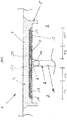
- Fig. 1 shows a joint filling profile 1 according to the invention.
- a joint 2 for example an expansion joint, is left between two adjacent floor panels 3 and 4. This usually results from building regulations or other necessities.
- a filler material 10 for example a foam insert, and a round cord 11 are arranged in a manner known per se, in order to prevent three-flank adhesion. Otherwise, the joint sealing compound would connect both the floor panels 3 and 4 and the floor below with one another.
- a substantially horizontally extending joint widening 5 is formed, which on the outside forms rectangular grooves which extend substantially parallel to the joint 2.
- the joint 2 is filled with joint sealing compound 9 flush with the surface up to the joint widening 5.
- the joint filling profile 1 has a vertical leg 6 arranged in the joint 2 and a profile body 7 arranged in the joint widening 5.
- the vertical leg 6 and the profile body 7 of the joint filling profile 1 are not formed in one piece, but rather separated from one another. This is achieved in that a separating material 8 is arranged between the vertical leg 6 and the profile body 7.
- the separating material 8 can be, for example, a mechanically acting intermediate layer, for example a metal foil, in particular an aluminum foil.
- the vertical legs 6 and profile body 7 are formed from a joint sealing compound 9.
- the vertical leg 6 can be designed as a compression block, which is formed, for example, from an elastic material, such as a foam material. In any case, however, it is provided that the vertical limb 6 and the profile body 7 are separated from one another by means of the separating material 8, that is to say that there is no direct connection between the profile body 7 and the vertical limb 6.
- the profile body 7 For each base plate 3 or 4, the profile body 7 provides a first section 12 or 13 adjacent to the joint 2 or the vertical web 6, in which first section 12 or 13 the profile body 7 rests without connection with the interposition of a separating material 8 on the associated base plate 3 or 4 .
- a continuous area is thus created which extends over the first section 12 formed in the area of the base plate 3, the joint 2 and the first section 13 formed in the area of the base plate 4, in which there is no direct connection between the profile body 7 and the substrate consists.
- the profile body has second sections 14 and 15 adjacent to the first sections 12 and 13, respectively. In the area of these sections 14 and 15, there is a direct connection between the joint sealing compound 9 forming the profile body 7 and the subsurface formed by the respective base plates 3 and 4.
- a reinforcing mat 16, 17 made of longitudinal and transverse struts arranged in a grid-like manner is arranged on both sides of the joint 2.
- the reinforcement mat 16 extends over both sections 12, 14.
- the reinforcement mat 17 extends over the two sections 13, 15.
- the reinforcement mats 16, 17 are arranged leaving a gap 21 aligned with the joint 2 in the vertical direction with respect to the image plane .
- the gap 21 is filled with joint sealing compound 9 as part of the profile body 7.
- the reinforcement mats 16, 17 Due to their lattice-like structure, the reinforcement mats 16, 17 have openings formed between longitudinal and transverse struts, which are continuous for the joint sealing compound 9.
- the reinforcement mats 16, 17 rest in sections 14, 15 on spacers 18, 19, respectively. Overall, this ensures that the joint sealing compound 9 of the profile body 7 in the sections 14, 15 is in contact with the respective base plates 3, 4.
- Each spacer 18 or 19 can have a bearing element which runs in the longitudinal direction of the joint and is supported by support elements.
- the profile body 7 is thus largely free from stresses between the joint sealing compound 9 and the floor panels 3, 4.
- reinforcements in the form of dowels 20 are arranged within the profile body.
- the reinforcements are in this as well as in the other embodiments according to the Figures 1 to 3 optional.
- a plurality of dowels 20 are provided, which are arranged one behind the other in the longitudinal direction of the joint 2.
- the dowels 20 are preferably positioned adjacent to one another at equidistant intervals.
- Each dowel 20 has a sleeve and a rod received by the sleeve.
- a sleeve is formed longer in its longitudinal extension than the associated rod, that is, the longitudinal extension of the sleeve exceeds the longitudinal extension of the associated rod. This configuration makes it possible that the rod can move relative to the sleeve.
- the reinforcement mats 16, 17 are arranged between the dowels 20 and the spacers 18, 19. The dowels 20 rest on the reinforcement mats 16, 17 at least in the area of the reinforcement mats 16, 17 on both sides.
- the filler material 10 and the round cord 11 are first introduced into the joint 2.
- the vertical leg 6 is then formed, in the illustrated embodiment by the introduction of the casting compound 9 into the joint 2, the joint 2 being filled at least flush with the base of the joint widening 5. It is not excluded here that part of the vertical leg 6 protrudes into the widened joint 5. Nevertheless, the vertical limb 6 and the profile body 7 are completely separated from one another by the separating material 8.
- the respective joint-side end of the reinforcement mats 16, 17 can rest on the part of the vertical leg 6 protruding into the joint widening 5, with the interposition of the separating material 8.
- the combined height of the part of the vertical leg 6 protruding into the joint widening 5 and of the separating material 8 corresponds to the height of the spacers 18, 19. This ensures that the reinforcement mats 16, 17 are aligned horizontally in the widened joint 5. In this way, a particularly homogeneous stress absorption on the part of the reinforcement mats 16, 17 is achieved.
- the separating material 8 is then introduced, which in the exemplary embodiment shown extends over the joint 2 and the two first sections 12 and 13 of the floor panels 3 and 4, respectively.
- the spacers 18 and 19 are then positioned within the widened joint 5, on which the reinforcement mats 16, 17 are then placed.
- the dowels 20 are then placed on the reinforcement mats 16, 17.
- joint sealing compound 9 is used to form the profile body 7 in the Joint widening 5 introduced, the joint widening 5 being filled with joint sealing compound 9 flush with the surface with the floor slabs 3 and 4.
- the particular advantage of the joint filling profile according to the invention is that there can be no tears or cracks in the transition area between the profile body 7 and the vertical leg 6 or in the overlapping area of the separating material 8 and reinforcement mats 16, 17, which would then lead to undesirable detachments. Furthermore, the connection-free design of the profile body 7 in the area of the first sections 12 and 13 and the joint 2 creates a comparatively large area in which the joint filling profile 1 can perform free expansion work to compensate for mechanical and / or thermal loads. Undesired detachments and / or flank tears are thus avoided.
- the vertical limb 6 does not stand in the way of such an expansion work, since according to the invention there is no direct connection between the vertical limb 6 and the profile body 7.
- Figure 2 shows a further embodiment of the invention in which, in addition to the first separating material 8, a second separating material 22 in the form of an aluminum foil is arranged between the vertical web 6 and the profile body 7.
- the separating material 22 rests directly on the first separating material 8. In cross section, it ends flush with the first separating material 8.
- Reinforcing mats 16, 17 are also shown.
- the reinforcing mat 16 extends over both sections 12, 14.
- the reinforcing mat 17 extends over the two sections 13, 15.
- the reinforcing mats 16, 17 are left with one with respect to the image plane in the height direction with the joint 2 aligned gap 21 arranged.
- the gap 21 is filled with joint sealing compound 9 as part of the profile body 7.
- the reinforcement mats 16, 17 lie in the first sections 12, 13 directly on the second separating material 22.
- the arrangement of the first and second separating material 8, 22 on top of one another results in a double layer.
- the overlapping of the respective reinforcement mat 16, 17 with the double-layer separating material 8, 22 results in a three-layer structure. Due to the multiple layers in certain areas a particularly good force release and absorption within the joint filling profile 1 is achieved. It is therefore particularly insensitive to all possible causes of crack formation.
- Figure 3 shows a further embodiment of the invention without reinforcement mats 16, 17, in which, in addition to the first separating material 8, a second separating material 22 in the form of an aluminum foil is arranged between the vertical web 6 and the profile body 7.
- the separating material 22 rests directly on the first separating material 8. In cross section, it ends flush with the first separating material 8.
- the reinforcement 20 rests directly on the second separating material 22 in the first sections 12, 13.
Landscapes
- Engineering & Computer Science (AREA)
- Architecture (AREA)
- Civil Engineering (AREA)
- Structural Engineering (AREA)
- Physics & Mathematics (AREA)
- Electromagnetism (AREA)
- Building Environments (AREA)
- Road Paving Structures (AREA)
- Bridges Or Land Bridges (AREA)
Applications Claiming Priority (1)
| Application Number | Priority Date | Filing Date | Title |
|---|---|---|---|
| DE202019101140.8U DE202019101140U1 (de) | 2019-02-28 | 2019-02-28 | Fugenfüllungsprofil |
Publications (2)
| Publication Number | Publication Date |
|---|---|
| EP3702531A1 true EP3702531A1 (fr) | 2020-09-02 |
| EP3702531B1 EP3702531B1 (fr) | 2023-07-12 |
Family
ID=69468388
Family Applications (1)
| Application Number | Title | Priority Date | Filing Date |
|---|---|---|---|
| EP20155300.5A Active EP3702531B1 (fr) | 2019-02-28 | 2020-02-04 | Profilé de remplissage de joint |
Country Status (3)
| Country | Link |
|---|---|
| US (1) | US11359367B2 (fr) |
| EP (1) | EP3702531B1 (fr) |
| DE (1) | DE202019101140U1 (fr) |
Families Citing this family (2)
| Publication number | Priority date | Publication date | Assignee | Title |
|---|---|---|---|---|
| US11326311B2 (en) * | 2016-03-07 | 2022-05-10 | Schul International Co., Llc | Durable joint seal system with flexibly attached cover plate and rib |
| CN114657871A (zh) * | 2022-03-04 | 2022-06-24 | 浙江交工集团股份有限公司 | 一种装配式无缝伸缩缝骨架 |
Citations (10)
| Publication number | Priority date | Publication date | Assignee | Title |
|---|---|---|---|---|
| AT375984B (de) | 1981-08-27 | 1984-09-25 | Kratochvil Guenter | Fahrbahnuebergang |
| EP0505010B1 (fr) | 1991-03-22 | 1997-09-10 | N.V. Bekaert S.A. | Procédé de renforcement d'une couche de revêtement de sol |
| WO2007053119A1 (fr) | 2005-11-04 | 2007-05-10 | National University Of Singapore | Procede d'application de milieu de revetement et panneau preforme |
| DE10002866B4 (de) | 2000-01-24 | 2008-02-07 | Sk Wiegrink Beteiligungs Gmbh | Verfahren zur Herstellung eines Fugenfüllungsprofils |
| EP2098651A2 (fr) | 2008-03-03 | 2009-09-09 | SK Wiegrink Beteiligungs GmbH | Profilé de remplissage de joint et son procédé de fabrication |
| NL2001419C2 (nl) * | 2008-03-28 | 2009-09-29 | Rasenberg Wegenbouw B V | Werkwijze voor het verschaffen van een voegovergang. |
| KR20100089616A (ko) * | 2009-02-04 | 2010-08-12 | (주)네오이엔지 | 보강망을 구비한 신축이음 |
| KR20100123192A (ko) * | 2009-05-14 | 2010-11-24 | 조영철 | 신축이음 조성물, 신축이음 조성물 제조방법, 탄성 폴리머를 이용한 신축이음 및 그 시공방법 |
| DE102015118223A1 (de) | 2015-10-26 | 2017-04-27 | Ibotac GmbH & Co. KG | Fugenausbildung |
| EP3241953A1 (fr) | 2016-05-06 | 2017-11-08 | SK Wiegrink Beteiligungs GmbH | Profilé de remplissage de joint |
Family Cites Families (23)
| Publication number | Priority date | Publication date | Assignee | Title |
|---|---|---|---|---|
| US2184148A (en) * | 1937-06-01 | 1939-12-19 | Carey Philip Mfg Co | Paving joint construction |
| US3447430A (en) * | 1967-03-16 | 1969-06-03 | Argil J May Mfg & Distribution | Expansion joint cover |
| US3827204A (en) * | 1972-03-14 | 1974-08-06 | Thiokol Chemical Corp | Sealed joint for sectionalized flooring and method of making the same |
| FR2308747A1 (fr) * | 1975-04-22 | 1976-11-19 | Sept Sarl | Dispositif de jointoiement de structures en beton |
| US4063840A (en) * | 1977-03-09 | 1977-12-20 | The General Tire & Rubber Company | Expansion joint seal assembly |
| DE3361123D1 (en) * | 1982-07-23 | 1985-12-05 | Alh Syst Ltd | Expansion joint |
| US4784516A (en) * | 1988-02-10 | 1988-11-15 | Harco Research, Inc. | Traffic bearing expansion joint cover and method of preparing same |
| CA1310219C (fr) * | 1989-05-04 | 1992-11-17 | Joseph D. George | Joints de dilatation; procede et dispositif de fabrication et d'installation |
| US5024554A (en) * | 1990-02-22 | 1991-06-18 | Koch Materials Company | Bridge joint construction |
| US5171100A (en) * | 1990-12-12 | 1992-12-15 | Bergstedt Jan Eric O | Preformed expansion joint system |
| US5513927A (en) * | 1994-08-01 | 1996-05-07 | Baker; Richard J. | Bridge joint construction |
| DE19537444C2 (de) * | 1995-10-07 | 2000-09-07 | Otto Elisabeth | Abdichtungsprofil zum Abdichten einer Fuge zwischen zwei Betonplatten |
| AU5619899A (en) * | 1998-08-17 | 2000-03-14 | Karl Kortmann | Concrete element with a preliminary reinforced adhering layer |
| US6668507B2 (en) * | 2000-12-08 | 2003-12-30 | Paulin A. Blanchet | Hurricane resistant precast composite building system |
| DE10111466A1 (de) * | 2001-03-09 | 2002-09-12 | Aribert Mueller | Wasserdichte Dehnungsfuge |
| NZ533314A (en) * | 2001-11-28 | 2006-04-28 | James Hardie Int Finance Bv | Caulkless panelized wall system |
| US8826481B1 (en) * | 2011-10-27 | 2014-09-09 | Versaflex, Inc. | Waterproof expansion joint |
| US8790038B2 (en) * | 2012-11-30 | 2014-07-29 | Dynamic Surface Applications, Ltd. | Expansion joint and methods of preparing same |
| EP3099859B1 (fr) * | 2014-01-28 | 2020-04-22 | Rangoni, Cristiano | Procédé d'imperméabilisation de ponts de chemin de fer |
| US9404581B1 (en) * | 2014-02-28 | 2016-08-02 | Schul International Company, LLC | Joint seal system |
| CA2975519C (fr) * | 2015-02-02 | 2023-04-25 | Watson Bowman Acme Corporation | Garniture de joint de dilatation et joint de dilatation |
| US11326311B2 (en) * | 2016-03-07 | 2022-05-10 | Schul International Co., Llc | Durable joint seal system with flexibly attached cover plate and rib |
| US10036131B2 (en) * | 2016-11-04 | 2018-07-31 | Russell Pascetta | Method for waterproofing a bridge expansion joint |
-
2019
- 2019-02-28 DE DE202019101140.8U patent/DE202019101140U1/de active Active
-
2020
- 2020-02-04 EP EP20155300.5A patent/EP3702531B1/fr active Active
- 2020-02-05 US US16/782,226 patent/US11359367B2/en active Active
Patent Citations (10)
| Publication number | Priority date | Publication date | Assignee | Title |
|---|---|---|---|---|
| AT375984B (de) | 1981-08-27 | 1984-09-25 | Kratochvil Guenter | Fahrbahnuebergang |
| EP0505010B1 (fr) | 1991-03-22 | 1997-09-10 | N.V. Bekaert S.A. | Procédé de renforcement d'une couche de revêtement de sol |
| DE10002866B4 (de) | 2000-01-24 | 2008-02-07 | Sk Wiegrink Beteiligungs Gmbh | Verfahren zur Herstellung eines Fugenfüllungsprofils |
| WO2007053119A1 (fr) | 2005-11-04 | 2007-05-10 | National University Of Singapore | Procede d'application de milieu de revetement et panneau preforme |
| EP2098651A2 (fr) | 2008-03-03 | 2009-09-09 | SK Wiegrink Beteiligungs GmbH | Profilé de remplissage de joint et son procédé de fabrication |
| NL2001419C2 (nl) * | 2008-03-28 | 2009-09-29 | Rasenberg Wegenbouw B V | Werkwijze voor het verschaffen van een voegovergang. |
| KR20100089616A (ko) * | 2009-02-04 | 2010-08-12 | (주)네오이엔지 | 보강망을 구비한 신축이음 |
| KR20100123192A (ko) * | 2009-05-14 | 2010-11-24 | 조영철 | 신축이음 조성물, 신축이음 조성물 제조방법, 탄성 폴리머를 이용한 신축이음 및 그 시공방법 |
| DE102015118223A1 (de) | 2015-10-26 | 2017-04-27 | Ibotac GmbH & Co. KG | Fugenausbildung |
| EP3241953A1 (fr) | 2016-05-06 | 2017-11-08 | SK Wiegrink Beteiligungs GmbH | Profilé de remplissage de joint |
Also Published As
| Publication number | Publication date |
|---|---|
| US11359367B2 (en) | 2022-06-14 |
| US20200277779A1 (en) | 2020-09-03 |
| DE202019101140U1 (de) | 2020-05-29 |
| EP3702531B1 (fr) | 2023-07-12 |
Similar Documents
| Publication | Publication Date | Title |
|---|---|---|
| DE69907752T2 (de) | Verfahren und vorrichtung zum abdichten von fugen oder rissen in hydraulischen werken, beton und mauerwerk | |
| DE2657141A1 (de) | Feuerschutzelement, insbesondere feuerschutztuere oder feuerschutztor | |
| EP3702531B1 (fr) | Profilé de remplissage de joint | |
| EP3460135B1 (fr) | Profilé de remplissage de joint | |
| EP0892118A1 (fr) | Elément de construction pour l' isolation thermique | |
| DE2647839C3 (de) | Aus Kunststoff bestehendes Fugendichtungsprofil zum Abschließen einer Fuge | |
| EP1482101A1 (fr) | Elément de construction, procédé pour fabriquer des éléments de construction et moyens de liaison pour élément de construction | |
| DE102012102800B4 (de) | Fugenprofil und Anordnung aus mehreren Fugenprofilen für Fugen in einem Betonbelag | |
| DE4421839C1 (de) | Schalungstafel aus Beton | |
| CH701639B1 (de) | Sollrissfugeneinlage | |
| DE875403C (de) | Bauelement und Verfahren zu seiner Herstellung | |
| DE102009054028A1 (de) | Fugenprofil | |
| DE3214502C2 (fr) | ||
| DE102019110683A1 (de) | Vorrichtung zur Abdichtung von Betonfugen | |
| WO2012126025A1 (fr) | Dispositif pour réaliser un joint de dilatation | |
| DE3104600C2 (de) | Betonfertigteil für die Herstellung von Balkonen und dergleichen sowie Gebäude unter Verwendung dieses Fertigteils | |
| EP2088240A2 (fr) | Système et procédé de remplissage d'un joint entre un rail et une surface limitrophe | |
| DE3036620C2 (de) | Vorrichtung zum Schutz von Bauwerksteilen aus Beton gegen Feuchtigkeit | |
| DE102019130867A1 (de) | Vorrichtung zur Abdichtung von Betonfugen | |
| DE10136819B4 (de) | Bewehrungselement für flächige Betonteile | |
| EP1420128A1 (fr) | Surface en béton et son procédé de fabrication | |
| DE20119630U1 (de) | Abschalelement für eine Betonteiltrennfläche | |
| AT523809A2 (de) | Deckenrandschalungselement | |
| DE60300554T2 (de) | Doppelschalige Wand mit Dehnfuge | |
| DE8103468U1 (de) | Plattenfoermiges betonfertigteil fuer die herstellung von balkonen und dergleichen |
Legal Events
| Date | Code | Title | Description |
|---|---|---|---|
| PUAI | Public reference made under article 153(3) epc to a published international application that has entered the european phase |
Free format text: ORIGINAL CODE: 0009012 |
|
| STAA | Information on the status of an ep patent application or granted ep patent |
Free format text: STATUS: THE APPLICATION HAS BEEN PUBLISHED |
|
| AK | Designated contracting states |
Kind code of ref document: A1 Designated state(s): AL AT BE BG CH CY CZ DE DK EE ES FI FR GB GR HR HU IE IS IT LI LT LU LV MC MK MT NL NO PL PT RO RS SE SI SK SM TR |
|
| AX | Request for extension of the european patent |
Extension state: BA ME |
|
| STAA | Information on the status of an ep patent application or granted ep patent |
Free format text: STATUS: REQUEST FOR EXAMINATION WAS MADE |
|
| 17P | Request for examination filed |
Effective date: 20201208 |
|
| RBV | Designated contracting states (corrected) |
Designated state(s): AL AT BE BG CH CY CZ DE DK EE ES FI FR GB GR HR HU IE IS IT LI LT LU LV MC MK MT NL NO PL PT RO RS SE SI SK SM TR |
|
| REG | Reference to a national code |
Ref country code: DE Ipc: E04F0015140000 Ref country code: DE Ref legal event code: R079 Ref document number: 502020004088 Country of ref document: DE Free format text: PREVIOUS MAIN CLASS: E01C0011040000 Ipc: E04F0015140000 |
|
| GRAP | Despatch of communication of intention to grant a patent |
Free format text: ORIGINAL CODE: EPIDOSNIGR1 |
|
| STAA | Information on the status of an ep patent application or granted ep patent |
Free format text: STATUS: GRANT OF PATENT IS INTENDED |
|
| RIC1 | Information provided on ipc code assigned before grant |
Ipc: E04B 1/68 20060101ALN20230131BHEP Ipc: E01C 11/04 20060101ALN20230131BHEP Ipc: E04F 15/14 20060101AFI20230131BHEP |
|
| INTG | Intention to grant announced |
Effective date: 20230217 |
|
| GRAS | Grant fee paid |
Free format text: ORIGINAL CODE: EPIDOSNIGR3 |
|
| GRAA | (expected) grant |
Free format text: ORIGINAL CODE: 0009210 |
|
| STAA | Information on the status of an ep patent application or granted ep patent |
Free format text: STATUS: THE PATENT HAS BEEN GRANTED |
|
| P01 | Opt-out of the competence of the unified patent court (upc) registered |
Effective date: 20230523 |
|
| AK | Designated contracting states |
Kind code of ref document: B1 Designated state(s): AL AT BE BG CH CY CZ DE DK EE ES FI FR GB GR HR HU IE IS IT LI LT LU LV MC MK MT NL NO PL PT RO RS SE SI SK SM TR |
|
| REG | Reference to a national code |
Ref country code: CH Ref legal event code: EP |
|
| REG | Reference to a national code |
Ref country code: DE Ref legal event code: R096 Ref document number: 502020004088 Country of ref document: DE |
|
| REG | Reference to a national code |
Ref country code: IE Ref legal event code: FG4D Free format text: LANGUAGE OF EP DOCUMENT: GERMAN |
|
| REG | Reference to a national code |
Ref country code: NL Ref legal event code: FP |
|
| REG | Reference to a national code |
Ref country code: LT Ref legal event code: MG9D |
|
| PG25 | Lapsed in a contracting state [announced via postgrant information from national office to epo] |
Ref country code: GR Free format text: LAPSE BECAUSE OF FAILURE TO SUBMIT A TRANSLATION OF THE DESCRIPTION OR TO PAY THE FEE WITHIN THE PRESCRIBED TIME-LIMIT Effective date: 20231013 |
|
| PG25 | Lapsed in a contracting state [announced via postgrant information from national office to epo] |
Ref country code: ES Free format text: LAPSE BECAUSE OF FAILURE TO SUBMIT A TRANSLATION OF THE DESCRIPTION OR TO PAY THE FEE WITHIN THE PRESCRIBED TIME-LIMIT Effective date: 20230712 |
|
| PG25 | Lapsed in a contracting state [announced via postgrant information from national office to epo] |
Ref country code: IS Free format text: LAPSE BECAUSE OF FAILURE TO SUBMIT A TRANSLATION OF THE DESCRIPTION OR TO PAY THE FEE WITHIN THE PRESCRIBED TIME-LIMIT Effective date: 20231112 |
|
| PG25 | Lapsed in a contracting state [announced via postgrant information from national office to epo] |
Ref country code: SE Free format text: LAPSE BECAUSE OF FAILURE TO SUBMIT A TRANSLATION OF THE DESCRIPTION OR TO PAY THE FEE WITHIN THE PRESCRIBED TIME-LIMIT Effective date: 20230712 Ref country code: RS Free format text: LAPSE BECAUSE OF FAILURE TO SUBMIT A TRANSLATION OF THE DESCRIPTION OR TO PAY THE FEE WITHIN THE PRESCRIBED TIME-LIMIT Effective date: 20230712 Ref country code: PT Free format text: LAPSE BECAUSE OF FAILURE TO SUBMIT A TRANSLATION OF THE DESCRIPTION OR TO PAY THE FEE WITHIN THE PRESCRIBED TIME-LIMIT Effective date: 20231113 Ref country code: NO Free format text: LAPSE BECAUSE OF FAILURE TO SUBMIT A TRANSLATION OF THE DESCRIPTION OR TO PAY THE FEE WITHIN THE PRESCRIBED TIME-LIMIT Effective date: 20231012 Ref country code: LV Free format text: LAPSE BECAUSE OF FAILURE TO SUBMIT A TRANSLATION OF THE DESCRIPTION OR TO PAY THE FEE WITHIN THE PRESCRIBED TIME-LIMIT Effective date: 20230712 Ref country code: LT Free format text: LAPSE BECAUSE OF FAILURE TO SUBMIT A TRANSLATION OF THE DESCRIPTION OR TO PAY THE FEE WITHIN THE PRESCRIBED TIME-LIMIT Effective date: 20230712 Ref country code: IS Free format text: LAPSE BECAUSE OF FAILURE TO SUBMIT A TRANSLATION OF THE DESCRIPTION OR TO PAY THE FEE WITHIN THE PRESCRIBED TIME-LIMIT Effective date: 20231112 Ref country code: HR Free format text: LAPSE BECAUSE OF FAILURE TO SUBMIT A TRANSLATION OF THE DESCRIPTION OR TO PAY THE FEE WITHIN THE PRESCRIBED TIME-LIMIT Effective date: 20230712 Ref country code: GR Free format text: LAPSE BECAUSE OF FAILURE TO SUBMIT A TRANSLATION OF THE DESCRIPTION OR TO PAY THE FEE WITHIN THE PRESCRIBED TIME-LIMIT Effective date: 20231013 Ref country code: FI Free format text: LAPSE BECAUSE OF FAILURE TO SUBMIT A TRANSLATION OF THE DESCRIPTION OR TO PAY THE FEE WITHIN THE PRESCRIBED TIME-LIMIT Effective date: 20230712 Ref country code: ES Free format text: LAPSE BECAUSE OF FAILURE TO SUBMIT A TRANSLATION OF THE DESCRIPTION OR TO PAY THE FEE WITHIN THE PRESCRIBED TIME-LIMIT Effective date: 20230712 |
|
| PG25 | Lapsed in a contracting state [announced via postgrant information from national office to epo] |
Ref country code: PL Free format text: LAPSE BECAUSE OF FAILURE TO SUBMIT A TRANSLATION OF THE DESCRIPTION OR TO PAY THE FEE WITHIN THE PRESCRIBED TIME-LIMIT Effective date: 20230712 |
|
| REG | Reference to a national code |
Ref country code: DE Ref legal event code: R097 Ref document number: 502020004088 Country of ref document: DE |
|
| PG25 | Lapsed in a contracting state [announced via postgrant information from national office to epo] |
Ref country code: SM Free format text: LAPSE BECAUSE OF FAILURE TO SUBMIT A TRANSLATION OF THE DESCRIPTION OR TO PAY THE FEE WITHIN THE PRESCRIBED TIME-LIMIT Effective date: 20230712 Ref country code: RO Free format text: LAPSE BECAUSE OF FAILURE TO SUBMIT A TRANSLATION OF THE DESCRIPTION OR TO PAY THE FEE WITHIN THE PRESCRIBED TIME-LIMIT Effective date: 20230712 Ref country code: EE Free format text: LAPSE BECAUSE OF FAILURE TO SUBMIT A TRANSLATION OF THE DESCRIPTION OR TO PAY THE FEE WITHIN THE PRESCRIBED TIME-LIMIT Effective date: 20230712 Ref country code: DK Free format text: LAPSE BECAUSE OF FAILURE TO SUBMIT A TRANSLATION OF THE DESCRIPTION OR TO PAY THE FEE WITHIN THE PRESCRIBED TIME-LIMIT Effective date: 20230712 Ref country code: CZ Free format text: LAPSE BECAUSE OF FAILURE TO SUBMIT A TRANSLATION OF THE DESCRIPTION OR TO PAY THE FEE WITHIN THE PRESCRIBED TIME-LIMIT Effective date: 20230712 Ref country code: SK Free format text: LAPSE BECAUSE OF FAILURE TO SUBMIT A TRANSLATION OF THE DESCRIPTION OR TO PAY THE FEE WITHIN THE PRESCRIBED TIME-LIMIT Effective date: 20230712 |
|
| PLBE | No opposition filed within time limit |
Free format text: ORIGINAL CODE: 0009261 |
|
| STAA | Information on the status of an ep patent application or granted ep patent |
Free format text: STATUS: NO OPPOSITION FILED WITHIN TIME LIMIT |
|
| PG25 | Lapsed in a contracting state [announced via postgrant information from national office to epo] |
Ref country code: IT Free format text: LAPSE BECAUSE OF FAILURE TO SUBMIT A TRANSLATION OF THE DESCRIPTION OR TO PAY THE FEE WITHIN THE PRESCRIBED TIME-LIMIT Effective date: 20230712 |
|
| 26N | No opposition filed |
Effective date: 20240415 |
|
| PG25 | Lapsed in a contracting state [announced via postgrant information from national office to epo] |
Ref country code: SI Free format text: LAPSE BECAUSE OF FAILURE TO SUBMIT A TRANSLATION OF THE DESCRIPTION OR TO PAY THE FEE WITHIN THE PRESCRIBED TIME-LIMIT Effective date: 20230712 |
|
| PG25 | Lapsed in a contracting state [announced via postgrant information from national office to epo] |
Ref country code: MC Free format text: LAPSE BECAUSE OF FAILURE TO SUBMIT A TRANSLATION OF THE DESCRIPTION OR TO PAY THE FEE WITHIN THE PRESCRIBED TIME-LIMIT Effective date: 20230712 |
|
| PG25 | Lapsed in a contracting state [announced via postgrant information from national office to epo] |
Ref country code: BG Free format text: LAPSE BECAUSE OF FAILURE TO SUBMIT A TRANSLATION OF THE DESCRIPTION OR TO PAY THE FEE WITHIN THE PRESCRIBED TIME-LIMIT Effective date: 20230712 |
|
| PG25 | Lapsed in a contracting state [announced via postgrant information from national office to epo] |
Ref country code: BG Free format text: LAPSE BECAUSE OF FAILURE TO SUBMIT A TRANSLATION OF THE DESCRIPTION OR TO PAY THE FEE WITHIN THE PRESCRIBED TIME-LIMIT Effective date: 20230712 |
|
| PG25 | Lapsed in a contracting state [announced via postgrant information from national office to epo] |
Ref country code: IE Free format text: LAPSE BECAUSE OF NON-PAYMENT OF DUE FEES Effective date: 20240204 |
|
| PG25 | Lapsed in a contracting state [announced via postgrant information from national office to epo] |
Ref country code: IE Free format text: LAPSE BECAUSE OF NON-PAYMENT OF DUE FEES Effective date: 20240204 |
|
| PGFP | Annual fee paid to national office [announced via postgrant information from national office to epo] |
Ref country code: DE Payment date: 20250424 Year of fee payment: 6 |
|
| PG25 | Lapsed in a contracting state [announced via postgrant information from national office to epo] |
Ref country code: CY Free format text: LAPSE BECAUSE OF FAILURE TO SUBMIT A TRANSLATION OF THE DESCRIPTION OR TO PAY THE FEE WITHIN THE PRESCRIBED TIME-LIMIT; INVALID AB INITIO Effective date: 20200204 |
|
| PG25 | Lapsed in a contracting state [announced via postgrant information from national office to epo] |
Ref country code: HU Free format text: LAPSE BECAUSE OF FAILURE TO SUBMIT A TRANSLATION OF THE DESCRIPTION OR TO PAY THE FEE WITHIN THE PRESCRIBED TIME-LIMIT; INVALID AB INITIO Effective date: 20200204 |
|
| PG25 | Lapsed in a contracting state [announced via postgrant information from national office to epo] |
Ref country code: TR Free format text: LAPSE BECAUSE OF FAILURE TO SUBMIT A TRANSLATION OF THE DESCRIPTION OR TO PAY THE FEE WITHIN THE PRESCRIBED TIME-LIMIT Effective date: 20230712 |
|
| REG | Reference to a national code |
Ref country code: CH Ref legal event code: U11 Free format text: ST27 STATUS EVENT CODE: U-0-0-U10-U11 (AS PROVIDED BY THE NATIONAL OFFICE) Effective date: 20260301 |
|
| PGFP | Annual fee paid to national office [announced via postgrant information from national office to epo] |
Ref country code: NL Payment date: 20260218 Year of fee payment: 7 Ref country code: LU Payment date: 20260218 Year of fee payment: 7 |
|
| PGFP | Annual fee paid to national office [announced via postgrant information from national office to epo] |
Ref country code: GB Payment date: 20260220 Year of fee payment: 7 |
|
| PGFP | Annual fee paid to national office [announced via postgrant information from national office to epo] |
Ref country code: AT Payment date: 20260219 Year of fee payment: 7 |
|
| PGFP | Annual fee paid to national office [announced via postgrant information from national office to epo] |
Ref country code: BE Payment date: 20260218 Year of fee payment: 7 |
|
| PGFP | Annual fee paid to national office [announced via postgrant information from national office to epo] |
Ref country code: FR Payment date: 20260218 Year of fee payment: 7 |
|
| PGFP | Annual fee paid to national office [announced via postgrant information from national office to epo] |
Ref country code: CH Payment date: 20260301 Year of fee payment: 7 |