EP3702646A1 - Pièce de support de couronne dentée pour une roue dentée bi- ou multicomposant ainsi que roue dentée bi- ou multicomposant comportant une telle pièce de support de couronne dentée - Google Patents
Pièce de support de couronne dentée pour une roue dentée bi- ou multicomposant ainsi que roue dentée bi- ou multicomposant comportant une telle pièce de support de couronne dentée Download PDFInfo
- Publication number
- EP3702646A1 EP3702646A1 EP19159881.2A EP19159881A EP3702646A1 EP 3702646 A1 EP3702646 A1 EP 3702646A1 EP 19159881 A EP19159881 A EP 19159881A EP 3702646 A1 EP3702646 A1 EP 3702646A1
- Authority
- EP
- European Patent Office
- Prior art keywords
- carrier part
- ring
- projections
- extension
- gear
- Prior art date
- Legal status (The legal status is an assumption and is not a legal conclusion. Google has not performed a legal analysis and makes no representation as to the accuracy of the status listed.)
- Granted
Links
Images


Classifications
-
- F—MECHANICAL ENGINEERING; LIGHTING; HEATING; WEAPONS; BLASTING
- F16—ENGINEERING ELEMENTS AND UNITS; GENERAL MEASURES FOR PRODUCING AND MAINTAINING EFFECTIVE FUNCTIONING OF MACHINES OR INSTALLATIONS; THERMAL INSULATION IN GENERAL
- F16H—GEARING
- F16H55/00—Elements with teeth or friction surfaces for conveying motion; Worms, pulleys or sheaves for gearing mechanisms
- F16H55/02—Toothed members; Worms
- F16H55/12—Toothed members; Worms with body or rim assembled out of detachable parts
-
- F—MECHANICAL ENGINEERING; LIGHTING; HEATING; WEAPONS; BLASTING
- F16—ENGINEERING ELEMENTS AND UNITS; GENERAL MEASURES FOR PRODUCING AND MAINTAINING EFFECTIVE FUNCTIONING OF MACHINES OR INSTALLATIONS; THERMAL INSULATION IN GENERAL
- F16H—GEARING
- F16H55/00—Elements with teeth or friction surfaces for conveying motion; Worms, pulleys or sheaves for gearing mechanisms
- F16H55/02—Toothed members; Worms
- F16H55/06—Use of materials; Use of treatments of toothed members or worms to affect their intrinsic material properties
-
- F—MECHANICAL ENGINEERING; LIGHTING; HEATING; WEAPONS; BLASTING
- F16—ENGINEERING ELEMENTS AND UNITS; GENERAL MEASURES FOR PRODUCING AND MAINTAINING EFFECTIVE FUNCTIONING OF MACHINES OR INSTALLATIONS; THERMAL INSULATION IN GENERAL
- F16H—GEARING
- F16H55/00—Elements with teeth or friction surfaces for conveying motion; Worms, pulleys or sheaves for gearing mechanisms
- F16H55/02—Toothed members; Worms
- F16H55/08—Profiling
-
- F—MECHANICAL ENGINEERING; LIGHTING; HEATING; WEAPONS; BLASTING
- F16—ENGINEERING ELEMENTS AND UNITS; GENERAL MEASURES FOR PRODUCING AND MAINTAINING EFFECTIVE FUNCTIONING OF MACHINES OR INSTALLATIONS; THERMAL INSULATION IN GENERAL
- F16H—GEARING
- F16H55/00—Elements with teeth or friction surfaces for conveying motion; Worms, pulleys or sheaves for gearing mechanisms
- F16H55/02—Toothed members; Worms
- F16H55/17—Toothed wheels
-
- F—MECHANICAL ENGINEERING; LIGHTING; HEATING; WEAPONS; BLASTING
- F16—ENGINEERING ELEMENTS AND UNITS; GENERAL MEASURES FOR PRODUCING AND MAINTAINING EFFECTIVE FUNCTIONING OF MACHINES OR INSTALLATIONS; THERMAL INSULATION IN GENERAL
- F16H—GEARING
- F16H55/00—Elements with teeth or friction surfaces for conveying motion; Worms, pulleys or sheaves for gearing mechanisms
- F16H55/02—Toothed members; Worms
- F16H55/06—Use of materials; Use of treatments of toothed members or worms to affect their intrinsic material properties
- F16H2055/065—Moulded gears, e.g. inserts therefor
-
- F—MECHANICAL ENGINEERING; LIGHTING; HEATING; WEAPONS; BLASTING
- F16—ENGINEERING ELEMENTS AND UNITS; GENERAL MEASURES FOR PRODUCING AND MAINTAINING EFFECTIVE FUNCTIONING OF MACHINES OR INSTALLATIONS; THERMAL INSULATION IN GENERAL
- F16H—GEARING
- F16H55/00—Elements with teeth or friction surfaces for conveying motion; Worms, pulleys or sheaves for gearing mechanisms
- F16H55/02—Toothed members; Worms
- F16H55/17—Toothed wheels
- F16H2055/176—Ring gears with inner teeth
Definitions
- the present invention relates to a ring gear carrier part for a two- or multi-component gear.
- the invention also relates to a two- or multi-component gear with such a gear rim carrier part.
- Multi-component gears are for example in the EP 2 899 430 A1 and are characterized by the fact that they are made up of at least two different materials.
- the ring gear carrier part which forms the ring gear can be made of a first material, while the rest of the gear consists of a second material.
- One of the advantages of this configuration of two- or multi-component gears is that the material can be selected in accordance with the loads prevailing at the point of the gear.
- the ring gear carrier part with the ring gear is exposed to high wear and / or high forces, while the part connected to the ring gear carrier part, hereinafter referred to as the connecting part, typically has high torsional and tilting torques that must be absorbed.
- a two-component gear can therefore consist of a first plastic and a second plastic, for example, the first plastic being used for the ring gear carrier part and the second plastic being used for the connecting part.
- a particularly wear-resistant plastic can be selected for the first plastic, while the second plastic can be a self-reinforcing plastic, which can also be fiber-reinforced.
- the hub can be formed by an insert that can be made of metal.
- Two- or multi-component gears are increasingly being manufactured by injection molding, which is particularly the case when the two- or multi-component gears are made entirely or partially of plastic.
- injection molding which is particularly the case when the two- or multi-component gears are made entirely or partially of plastic.
- two frequently used injection molding processes are shown, namely on the one hand the screen gating method and on the other hand the point gating method.
- the ring gear carrier part can be injected. Due to the projections and depressions of the ring gear carrier part, the flow path of the material used and liquid when injected into the injection mold is unfavorable in that the material reaches some points within the injection mold significantly later than neighboring points. As a result, overflow channels form and the material cools down later than at the neighboring points.
- the finished ring gear carrier part therefore has inhomogeneities, as a result of which the maximum load capacity of gears which have such ring gear carrier parts is limited.
- the object of an embodiment of the present invention is to provide a gear rim carrier part which can be manufactured in such a way that it has fewer inhomogeneities and is therefore more resilient than known and comparable gear rim carrier parts. Furthermore, an embodiment of the present invention is based on the object of creating a two- or multi-component gear which has a gear rim carrier part that can be subjected to higher loads.
- two or more projections are present, they are arranged at a distance from one another. If there is only one projection, it is not circumferential, since otherwise no form fit between the ring gear carrier part and the connecting part is provided in the circumferential direction.
- the ring gear carrier part can be divided into the ring section and the extension, these being materially connected. In this respect, this subdivision is primarily to be seen in thought.
- the extension starts from the ring section and has a free end. At the free end, the extension has the first width, while the extension with the second width merges into the ring section.
- the first width and the second width relate to a plane running through the axis of rotation.
- the extension expands continuously or continuously in sections from the first width to the second width. “Continuously” is to be understood as meaning that the extension does not have any section in which the width of the extension decreases starting from the free end. “Continuously in sections” is to be understood as meaning that the extension also has sections in which the width of the extension remains the same.
- extension does not have any sections in which the width is reduced.
- “continuously” and “continuously in sections” should be understood to mean that the width of the extension does not change suddenly. It should be noted at this point that these statements only apply to the width of the extension as such, but not for the projections, which are to be considered separately from the extensions, but are materially related to the extension.
- a number of first projections and a number of second projections are arranged on the extension, the first projections starting from a first axial surface of the extension and the second projections starting from a second axial surface of the extension.
- the extension in this embodiment can be designed symmetrically in relation to a plane running through the axis of rotation in the area of the projections, the plane of symmetry running perpendicular to the axis of rotation. This also makes the flow path for the material during injection more uniform, so that the ring gear carrier part can be manufactured with increased homogeneity, which, as mentioned, manifests itself in an increased load capacity.
- the projections are arranged at a distance from one another. The two axial surfaces are accessible between two projections.
- first projections and the second projections can be arranged offset from one another in the circumferential direction. It is possible to avoid material accumulations, which also leads to an increased homogeneity of the ring gear carrier part.
- a number of radially inner projections and a number of radially outer projections can start from the first axial surface and / or from the second axial surface. Starting from the free end towards the ring part, there are two projections arranged radially spaced from one another, whereby the number of projections increases overall and the risk of the ring gear carrier part slipping relative to the connecting part can be reduced. It is also possible to provide more than two projections arranged radially spaced apart from one another within a plane extending through the axis of rotation, whereby the number of projections can be increased further.
- two or more of the projections can extend essentially along the Longitudinal extensions can be arranged.
- the greater the cross-sectional area of the projections the greater the risk of the ring gear carrier part slipping in relation to the connecting part.
- overflow channels can again form within the projections, which should be avoided for the reasons mentioned.
- a further developed embodiment is characterized in that the projections have a trapezoidal cross section. It has been found that when projections with a trapezoidal cross section are used, the ring gear carrier part can be manufactured with a high degree of homogeneity.
- the projections have an end face and / or a further end face which runs parallel to a plane running perpendicular to the axis of rotation.
- the ring gear carrier part can be manufactured with a high degree of homogeneity.
- the ring gear carrier part can be manufactured with a high degree of homogeneity.
- the ring gear carrier part can be manufactured with a high degree of homogeneity.
- the projections have an outer radial surface and an inner radial surface, the outer radial surface and / or the inner radial surface running parallel to the axis of rotation.
- the projections merge into the extension with a curved transition surface.
- the use of curved transition surfaces also equalize the flow path, which in turn leads to a high degree of homogeneity of the ring gear carrier part.
- the axial surfaces, the end surfaces, the further end surfaces, the outer radial surfaces and / or the inner radial surfaces are curved.
- the curvatures can be used to adjust the flow paths in such a way that the injection mold can be filled evenly, which in turn leads to increased homogeneity.
- the technical effects and advantages that can be achieved with the proposed two- or multi-component gear correspond to those that have been discussed for the present gear rim carrier part.
- the proposed design of the extension results in a flow path for the material that is liquid during injection, which leads to a significantly more uniform filling of the injection mold than is the case with sprocket carrier parts, which for example from the US 2014/007724 A1 are known. Consequently, the formation of overflow channels is reduced and the homogeneity of the proposed ring gear carrier part is increased.
- the load capacity of the proposed two- or multi-component gear is increased compared to known, comparable two- or multi-component gear.
- the first plastic can be a high-performance thermoplastic or an engineering thermoplastic
- the second plastic is a high-performance thermoplastic
- the two- or multi-component gear is designed as a spur gear, which can be used in many applications, in particular in spur gear drives that are widely used.
- the design of the proposed two- or multi-component gear is not limited to a spur gear.
- the proposed two- or multi-component gear can also be designed as a helical gear or worm gear, so that this can be used in a helical gear or a worm gear.
- Helical gears and worm gears are used, for example, in electromechanical drives for steering systems (EPS, " electrc power steering ").
- the two- or multi-component gear comprises an insert which is connected to the connecting part and is enclosed by the connecting part.
- the insert can be used to form a shaft-hub connection.
- the ring gear carrier part and the connecting part can be made from a first plastic or a second plastic, as mentioned, it is advisable to make the insert from metal for the formation of a highly resilient shaft-hub connection.
- the gear can be used in particular in planetary gears.
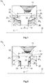
- FIG. 1 to 8 Different exemplary embodiments of a gear rim carrier part 10 according to the invention are shown in each case with the aid of sectional views, which can be used for a two-component gear 42 or a multi-component gear 50 (see FIG Figures 9 and 10 ).
- the two- or multi-component gear 42, 50 is concentric to an axis of rotation D arranged around which the two- or multi-component gear 42, 50 can rotate depending on the configuration.
- the cutting plane of the sectional views of the Figures 1 to 8 runs through the axis of rotation D. Only a half section of the ring gear carrier part 10 is shown.
- the ring gear carrier part 10 1 according to the invention according to the in Figure 1
- the first exemplary embodiment illustrated comprises a ring section 12 which runs in the circumferential direction in a ring around the axis of rotation D. Radially on the outside, the ring section 12 forms a ring gear 14 with which the ring gear carrier part 10 or the two- or multi-component gear 42, 50 provided with the ring gear carrier part 10 can be brought into meshing engagement with a gear not shown here.
- the two- or multi-component gear 42, 50 can be designed as a spur gear, helical gear or worm gear and can be brought into engagement with a correspondingly designed gear.
- the toothed ring carrier part 10 1 also has an extension 16 which, starting from the ring section 12, extends radially inward toward the axis of rotation D and forms a radially inner free end 18.
- the extension 16 has a first width a, which extends parallel to the axis of rotation D.
- the extension 16 has a second width b, which also extends parallel to the axis of rotation D.
- the extension 16 expands continuously from the first width a to the second width b.
- the width increases uniformly, so that the extension 16 is constructed in the shape of a funnel.
- the extension 16 has a first axial surface 20 and a second axial surface 22, which each enclose an equal axial surface angle ⁇ with a plane E extending perpendicular to the axis of rotation D.
- a number of projections 24 extend from the first axial surface 20 and the second axial surface 22, wherein in the first exemplary embodiment first projections 24 1 extend from the first axial surface 20 and second projections 24 2 extend from the second axial surface 22.
- the first projections 24 1 and the second projections 24 2 have the same dimensions, but point in different directions with respect to the axis of rotation D.
- first projections 24 1 and the second projections 24 2 are each arranged at a distance from one another in the circumferential direction, so that between two adjacent projections 24 1 , 24 2 a gap remains.
- first projections 24 1 and the second projections 24 2 are arranged offset from one another in the circumferential direction.
- the projections 24 1 , 24 2 are essentially trapezoidal and each include an end face 26, here a first end face 26 1 and a second end face 26 2 , an inner radial surface 28 and an outer radial surface 30.
- the inner radial surface 28 and the outer radial surface 30 run parallel to one another and parallel to the axis of rotation D, while the end face 26 encloses an end face angle ⁇ with a plane E extending perpendicular to the axis of rotation D.
- the face angle ⁇ is greater than the axial face angle ⁇ .
- the projections 24 merge into the extension 16 radially on the outside with a curved transition surface 32.
- the projections 24 each have a further end face 34 which includes a further end face angle ⁇ with a plane E extending perpendicular to the axis of rotation D.
- the further end face 34 runs parallel to the plane E running perpendicular to the axis of rotation D, which is why the further end face angle ⁇ is equal to zero.
- it can just as easily deviate from zero and be smaller or larger than the axial surface angle ⁇ .
- the further end face angle ⁇ can also be smaller or larger than the end face angle ⁇ .
- the two further end faces 34 of the first projections 24 1 and of the second projections 24 2 have a spacing c which, in the second exemplary embodiment, is equal to the second width b.
- the illustrated third embodiment of the ring gear carrier part 10 3 is largely the same as the second embodiment example of the ring gear carrier part 10 2 , but the first axial surface 20 and the second axial surface 22 are arched so that no clear axial surface angle ⁇ can be determined.
- the fourth exemplary embodiment of the ring gear carrier part 10 4 shown is largely the same as the first exemplary embodiment of the ring gear carrier part 10 1 , the end face angle ⁇ being almost equal to the axial surface angle ⁇ .
- the projections 24 in the fourth exemplary embodiment are approximately parallelogram-shaped.
- the illustrated fifth embodiment of the ring gear carrier part 10 5 is largely the same as the second embodiment example of the ring gear carrier part 10 2 , but the distance c between the two further end faces 34 is greater than the second width b.
- the projections 24 of the ring gear carrier part 10 6 have a first extension 36 1 and a second extension 36 2 , which extend essentially along the axis of rotation D.
- the end face 26 of the first extension 36 1 is curved, while the end face 26 of the second extension 36 2 has an end face angle ⁇ which is greater than the axial face angle ⁇ .
- the other end face 34 is also curved.
- the inner radial surface 28 and the outer radial surface 30 run parallel to one another and parallel to the axis of rotation D.
- the extensions 36 1 , 36 2 are separated from one another by a recess 37, but the recess 37 does not extend as far as the axial surfaces 20, 22.
- the projections 24 of the ring gear carrier part 10 7 according to the seventh exemplary embodiment also have the first extension 36 1 and the second extension 36 2 , but the first extension 36 1 has a first end face 26 1 and the second extension 36 2 has a second end face 26 2 that run parallel to each other.
- the ring gear carrier part 10 8 has a radially inner projection 38 and a radially outer projection 40.
- the radially inner projection 38 is arranged on a section 48 of the extension 16 in which the width of the extension 16 does not change.
- FIG 9 an embodiment of a two-component gear 42 is shown, which is designed as a ring gear 44.
- the ring gear 14 of the ring gear carrier part 10 is therefore arranged radially on the inside on the ring section 12, while the extension 16 extends radially outward from the ring section 12 and has a radially outer free end 46.
- a connecting part 49 is connected to the ring gear carrier part 10 in that it is injection molded around the extension 16.
- the ring gear carrier part 10 has the already mentioned section 48 in which the width of the extension 16 does not change.
- a radially outer projection 40 is arranged in this section 48.
- a radially inner projection 38 has an arched end face 26 and an arched inner radial face 28.
- a multi-component gear 50 in this case a three-component gear 50, which is designed as a spur gear 52, is shown on the basis of a side view.
- the three-component gear 50 comprises a ring gear carrier part 10 according to one of the exemplary embodiments discussed above, on the ring section 12 of which a ring gear 14 is arranged radially on the outside.
- the connecting part 49 is arranged radially inwards from the ring gear carrier part 10 and connected to it.
- the three-component gear 50 comprises an insert 54, which is arranged radially inward from the connecting part 49 and connected to it.
- the insert 54 forms a hub 56 with which the spur gear 52 can be connected to a shaft, not shown here.
Landscapes
- Engineering & Computer Science (AREA)
- General Engineering & Computer Science (AREA)
- Mechanical Engineering (AREA)
- Physics & Mathematics (AREA)
- Electromagnetism (AREA)
- Thermal Sciences (AREA)
- Gears, Cams (AREA)
Priority Applications (5)
| Application Number | Priority Date | Filing Date | Title |
|---|---|---|---|
| ES19159881T ES2906056T3 (es) | 2019-02-28 | 2019-02-28 | Pieza de soporte de corona dentada para una rueda dentada de dos o múltiples componentes, así como rueda dentada de dos o múltiples componentes con una pieza de soporte de corona dentada de este tipo |
| EP19159881.2A EP3702646B1 (fr) | 2019-02-28 | 2019-02-28 | Pièce de support de couronne dentée pour une roue dentée bi- ou multicomposant ainsi que roue dentée bi- ou multicomposant comportant une telle pièce de support de couronne dentée |
| KR1020200022231A KR102431505B1 (ko) | 2019-02-28 | 2020-02-24 | 2 부품- 또는 다중 부품 기어휠을 위한 기어 림 캐리어부 및 이와 같은 기어 림 캐리어부를 포함하는 2 부품- 또는 다중 부품 기어휠 |
| CN202010112226.6A CN111623104B (zh) | 2019-02-28 | 2020-02-24 | 用于两组件或多组件齿轮的齿圈载体部件以及齿轮 |
| US16/803,513 US11761526B2 (en) | 2019-02-28 | 2020-02-27 | Gear rim carrier part for a two- or multi-component gearwheel and two-or multi-component gearwheel having such a gear rim carrier part |
Applications Claiming Priority (1)
| Application Number | Priority Date | Filing Date | Title |
|---|---|---|---|
| EP19159881.2A EP3702646B1 (fr) | 2019-02-28 | 2019-02-28 | Pièce de support de couronne dentée pour une roue dentée bi- ou multicomposant ainsi que roue dentée bi- ou multicomposant comportant une telle pièce de support de couronne dentée |
Publications (2)
| Publication Number | Publication Date |
|---|---|
| EP3702646A1 true EP3702646A1 (fr) | 2020-09-02 |
| EP3702646B1 EP3702646B1 (fr) | 2021-11-10 |
Family
ID=65635490
Family Applications (1)
| Application Number | Title | Priority Date | Filing Date |
|---|---|---|---|
| EP19159881.2A Active EP3702646B1 (fr) | 2019-02-28 | 2019-02-28 | Pièce de support de couronne dentée pour une roue dentée bi- ou multicomposant ainsi que roue dentée bi- ou multicomposant comportant une telle pièce de support de couronne dentée |
Country Status (5)
| Country | Link |
|---|---|
| US (1) | US11761526B2 (fr) |
| EP (1) | EP3702646B1 (fr) |
| KR (1) | KR102431505B1 (fr) |
| CN (1) | CN111623104B (fr) |
| ES (1) | ES2906056T3 (fr) |
Families Citing this family (2)
| Publication number | Priority date | Publication date | Assignee | Title |
|---|---|---|---|---|
| DE102019211451A1 (de) * | 2019-07-31 | 2021-02-04 | Rolls-Royce Deutschland Ltd & Co Kg | Stegzahnrad |
| DE102021211483B3 (de) | 2021-10-12 | 2022-08-25 | Robert Bosch Gesellschaft mit beschränkter Haftung | Zahnrad aus Kunststoff für ein Lenkgetriebe |
Citations (4)
| Publication number | Priority date | Publication date | Assignee | Title |
|---|---|---|---|---|
| GB2064708A (en) * | 1979-11-29 | 1981-06-17 | Berg Winifred M | Improved composite gear and method of manufacture |
| US20140007724A1 (en) | 2011-02-18 | 2014-01-09 | Kwangduck A& T | Gear wheel and method for manufacturing gear wheel |
| EP2899430A1 (fr) | 2014-01-23 | 2015-07-29 | IMS Gear GmbH | Roue dentée à plusieurs composants |
| DE102014104284A1 (de) * | 2014-03-27 | 2015-10-01 | Robert Bosch Automotive Steering Gmbh | Zahnrad |
Family Cites Families (8)
| Publication number | Priority date | Publication date | Assignee | Title |
|---|---|---|---|---|
| DE102009028926A1 (de) * | 2009-08-27 | 2011-03-03 | Robert Bosch Gmbh | Zwischenlagereinrichtung mit Verzahnungsverstärkung für Starter |
| KR101346347B1 (ko) * | 2012-02-13 | 2013-12-31 | 남양공업주식회사 | Mdps 웜휠 및 제조방법 |
| KR20130100411A (ko) * | 2012-03-02 | 2013-09-11 | 주식회사 만도 | 전동식 동력 보조 조향장치의 웜휠 및 그 제조방법 |
| FR3022172B1 (fr) * | 2014-06-11 | 2016-05-27 | Jtekt Europe Sas | Procede de fabrication d’une roue dentee a jante coulee cannelee |
| KR102395672B1 (ko) * | 2015-12-15 | 2022-05-11 | 주식회사 만도 | 전동식 조향장치의 감속기 |
| US10843591B2 (en) * | 2016-01-19 | 2020-11-24 | Fisher & Company, Incorporated | Gear assembly for a seat adjuster |
| KR101906716B1 (ko) * | 2017-03-24 | 2018-10-11 | 주식회사 현대포리텍 | 전동식 조향장치용 웜휠 |
| GB201705587D0 (en) * | 2017-04-06 | 2017-05-24 | Lentus Composites Ltd | Gear |
-
2019
- 2019-02-28 ES ES19159881T patent/ES2906056T3/es active Active
- 2019-02-28 EP EP19159881.2A patent/EP3702646B1/fr active Active
-
2020
- 2020-02-24 CN CN202010112226.6A patent/CN111623104B/zh active Active
- 2020-02-24 KR KR1020200022231A patent/KR102431505B1/ko active Active
- 2020-02-27 US US16/803,513 patent/US11761526B2/en active Active
Patent Citations (4)
| Publication number | Priority date | Publication date | Assignee | Title |
|---|---|---|---|---|
| GB2064708A (en) * | 1979-11-29 | 1981-06-17 | Berg Winifred M | Improved composite gear and method of manufacture |
| US20140007724A1 (en) | 2011-02-18 | 2014-01-09 | Kwangduck A& T | Gear wheel and method for manufacturing gear wheel |
| EP2899430A1 (fr) | 2014-01-23 | 2015-07-29 | IMS Gear GmbH | Roue dentée à plusieurs composants |
| DE102014104284A1 (de) * | 2014-03-27 | 2015-10-01 | Robert Bosch Automotive Steering Gmbh | Zahnrad |
Also Published As
| Publication number | Publication date |
|---|---|
| CN111623104B (zh) | 2023-11-28 |
| ES2906056T3 (es) | 2022-04-13 |
| EP3702646B1 (fr) | 2021-11-10 |
| US11761526B2 (en) | 2023-09-19 |
| KR102431505B1 (ko) | 2022-08-11 |
| KR20200105415A (ko) | 2020-09-07 |
| US20200278018A1 (en) | 2020-09-03 |
| CN111623104A (zh) | 2020-09-04 |
Similar Documents
| Publication | Publication Date | Title |
|---|---|---|
| EP3800375B1 (fr) | Pièce de support de couronne dentée pour une roue dentée bi- ou multicomposant ainsi que roue dentée bi- ou multicomposant dotée d'une telle pièce de support de couronne dentée | |
| DE19648998B4 (de) | Anordnung, die bei Teleskopwellen anwendbar ist | |
| EP3459706B1 (fr) | Roue cylindrique destinée à être utilisée dans un engrenage cylindrique, engrenage pour un engrenage cylindrique, engrenage cylindrique doté d'un tel engrenage ainsi que procédé de fabrication d'une roue cylindrique | |
| EP3789635B1 (fr) | Roue dentée | |
| EP2459895B1 (fr) | Ensemble de bagues de synchronisation | |
| DE4229726C2 (de) | Anordnung aus Antriebswelle und aufgeschobener Nabe | |
| WO2007051453A2 (fr) | Moyeu de roue pourvu d'evidements axiaux formes entre les trous destines a des boulons de roue | |
| DE202016100792U1 (de) | Synchronisiervorrichtung und Schaltgetriebe mit einer solchen Synchronisiervorrichtung | |
| DE2937244A1 (de) | Wellen-naben-verbindung | |
| WO2015154920A1 (fr) | Dispositif de direction électromécanique comportant une roue dentée et procédé de fabrication d'une roue dentée | |
| EP3702646B1 (fr) | Pièce de support de couronne dentée pour une roue dentée bi- ou multicomposant ainsi que roue dentée bi- ou multicomposant comportant une telle pièce de support de couronne dentée | |
| DE2342424A1 (de) | Zahnstangengetriebe | |
| AT521959B1 (de) | Zahnrad | |
| EP0318669B1 (fr) | Accouplement à rondelles élastiques | |
| EP3211260B1 (fr) | Dispositif et procédé de synchronisation | |
| WO2017001127A1 (fr) | Transmission par vis sans fin et actionneur pourvu d'une transmission par vis sans fin | |
| DE102019110980A1 (de) | Planetenwälzgetriebe und Verfahren zur Montage eines Planetenwälzgetriebes | |
| EP3974680B1 (fr) | Roue à composants multiples, pignon et train épicycloïdal | |
| DE112021001392T5 (de) | Schraubenrad und herstellungsverfahren dafür | |
| EP0633128A1 (fr) | Procédé pour augmenter la tenue des liaisons mécaniques aux efforts de cisaillement | |
| AT519200B1 (de) | Klauenkupplungsvorrichtung | |
| DE102018111176A1 (de) | Synchronisierkupplung | |
| DE202019105432U1 (de) | Zahnkranzträgerteil für ein Zwei- oder Mehrkomponenten-Zahnrad sowie Zwei- oder Mehrkomponenten-Zahnrad mit einem derartigen Zahnkranzträgerteil | |
| DE2148043B2 (de) | Ringfoermig federndes, kegelfoermig aufgestelltes bauteil | |
| WO2017182039A1 (fr) | Manchon coulissant pour dispositif de synchronisation d'une boîte de vitesse et dispositif de synchronisation comprenant le manchon coulissant |
Legal Events
| Date | Code | Title | Description |
|---|---|---|---|
| PUAI | Public reference made under article 153(3) epc to a published international application that has entered the european phase |
Free format text: ORIGINAL CODE: 0009012 |
|
| STAA | Information on the status of an ep patent application or granted ep patent |
Free format text: STATUS: THE APPLICATION HAS BEEN PUBLISHED |
|
| AK | Designated contracting states |
Kind code of ref document: A1 Designated state(s): AL AT BE BG CH CY CZ DE DK EE ES FI FR GB GR HR HU IE IS IT LI LT LU LV MC MK MT NL NO PL PT RO RS SE SI SK SM TR |
|
| AX | Request for extension of the european patent |
Extension state: BA ME |
|
| STAA | Information on the status of an ep patent application or granted ep patent |
Free format text: STATUS: REQUEST FOR EXAMINATION WAS MADE |
|
| 17P | Request for examination filed |
Effective date: 20210224 |
|
| RBV | Designated contracting states (corrected) |
Designated state(s): AL AT BE BG CH CY CZ DE DK EE ES FI FR GB GR HR HU IE IS IT LI LT LU LV MC MK MT NL NO PL PT RO RS SE SI SK SM TR |
|
| GRAP | Despatch of communication of intention to grant a patent |
Free format text: ORIGINAL CODE: EPIDOSNIGR1 |
|
| STAA | Information on the status of an ep patent application or granted ep patent |
Free format text: STATUS: GRANT OF PATENT IS INTENDED |
|
| INTG | Intention to grant announced |
Effective date: 20210624 |
|
| GRAS | Grant fee paid |
Free format text: ORIGINAL CODE: EPIDOSNIGR3 |
|
| GRAA | (expected) grant |
Free format text: ORIGINAL CODE: 0009210 |
|
| STAA | Information on the status of an ep patent application or granted ep patent |
Free format text: STATUS: THE PATENT HAS BEEN GRANTED |
|
| AK | Designated contracting states |
Kind code of ref document: B1 Designated state(s): AL AT BE BG CH CY CZ DE DK EE ES FI FR GB GR HR HU IE IS IT LI LT LU LV MC MK MT NL NO PL PT RO RS SE SI SK SM TR |
|
| REG | Reference to a national code |
Ref country code: GB Ref legal event code: FG4D Free format text: NOT ENGLISH |
|
| REG | Reference to a national code |
Ref country code: AT Ref legal event code: REF Ref document number: 1446373 Country of ref document: AT Kind code of ref document: T Effective date: 20211115 Ref country code: CH Ref legal event code: EP |
|
| REG | Reference to a national code |
Ref country code: DE Ref legal event code: R096 Ref document number: 502019002670 Country of ref document: DE |
|
| REG | Reference to a national code |
Ref country code: IE Ref legal event code: FG4D Free format text: LANGUAGE OF EP DOCUMENT: GERMAN |
|
| REG | Reference to a national code |
Ref country code: LT Ref legal event code: MG9D |
|
| REG | Reference to a national code |
Ref country code: NL Ref legal event code: MP Effective date: 20211110 |
|
| REG | Reference to a national code |
Ref country code: ES Ref legal event code: FG2A Ref document number: 2906056 Country of ref document: ES Kind code of ref document: T3 Effective date: 20220413 |
|
| PG25 | Lapsed in a contracting state [announced via postgrant information from national office to epo] |
Ref country code: RS Free format text: LAPSE BECAUSE OF FAILURE TO SUBMIT A TRANSLATION OF THE DESCRIPTION OR TO PAY THE FEE WITHIN THE PRESCRIBED TIME-LIMIT Effective date: 20211110 Ref country code: LT Free format text: LAPSE BECAUSE OF FAILURE TO SUBMIT A TRANSLATION OF THE DESCRIPTION OR TO PAY THE FEE WITHIN THE PRESCRIBED TIME-LIMIT Effective date: 20211110 Ref country code: FI Free format text: LAPSE BECAUSE OF FAILURE TO SUBMIT A TRANSLATION OF THE DESCRIPTION OR TO PAY THE FEE WITHIN THE PRESCRIBED TIME-LIMIT Effective date: 20211110 Ref country code: BG Free format text: LAPSE BECAUSE OF FAILURE TO SUBMIT A TRANSLATION OF THE DESCRIPTION OR TO PAY THE FEE WITHIN THE PRESCRIBED TIME-LIMIT Effective date: 20220210 |
|
| PG25 | Lapsed in a contracting state [announced via postgrant information from national office to epo] |
Ref country code: IS Free format text: LAPSE BECAUSE OF FAILURE TO SUBMIT A TRANSLATION OF THE DESCRIPTION OR TO PAY THE FEE WITHIN THE PRESCRIBED TIME-LIMIT Effective date: 20220310 Ref country code: SE Free format text: LAPSE BECAUSE OF FAILURE TO SUBMIT A TRANSLATION OF THE DESCRIPTION OR TO PAY THE FEE WITHIN THE PRESCRIBED TIME-LIMIT Effective date: 20211110 Ref country code: PT Free format text: LAPSE BECAUSE OF FAILURE TO SUBMIT A TRANSLATION OF THE DESCRIPTION OR TO PAY THE FEE WITHIN THE PRESCRIBED TIME-LIMIT Effective date: 20220310 Ref country code: PL Free format text: LAPSE BECAUSE OF FAILURE TO SUBMIT A TRANSLATION OF THE DESCRIPTION OR TO PAY THE FEE WITHIN THE PRESCRIBED TIME-LIMIT Effective date: 20211110 Ref country code: NO Free format text: LAPSE BECAUSE OF FAILURE TO SUBMIT A TRANSLATION OF THE DESCRIPTION OR TO PAY THE FEE WITHIN THE PRESCRIBED TIME-LIMIT Effective date: 20220210 Ref country code: NL Free format text: LAPSE BECAUSE OF FAILURE TO SUBMIT A TRANSLATION OF THE DESCRIPTION OR TO PAY THE FEE WITHIN THE PRESCRIBED TIME-LIMIT Effective date: 20211110 Ref country code: LV Free format text: LAPSE BECAUSE OF FAILURE TO SUBMIT A TRANSLATION OF THE DESCRIPTION OR TO PAY THE FEE WITHIN THE PRESCRIBED TIME-LIMIT Effective date: 20211110 Ref country code: HR Free format text: LAPSE BECAUSE OF FAILURE TO SUBMIT A TRANSLATION OF THE DESCRIPTION OR TO PAY THE FEE WITHIN THE PRESCRIBED TIME-LIMIT Effective date: 20211110 Ref country code: GR Free format text: LAPSE BECAUSE OF FAILURE TO SUBMIT A TRANSLATION OF THE DESCRIPTION OR TO PAY THE FEE WITHIN THE PRESCRIBED TIME-LIMIT Effective date: 20220211 |
|
| PG25 | Lapsed in a contracting state [announced via postgrant information from national office to epo] |
Ref country code: SM Free format text: LAPSE BECAUSE OF FAILURE TO SUBMIT A TRANSLATION OF THE DESCRIPTION OR TO PAY THE FEE WITHIN THE PRESCRIBED TIME-LIMIT Effective date: 20211110 Ref country code: SK Free format text: LAPSE BECAUSE OF FAILURE TO SUBMIT A TRANSLATION OF THE DESCRIPTION OR TO PAY THE FEE WITHIN THE PRESCRIBED TIME-LIMIT Effective date: 20211110 Ref country code: RO Free format text: LAPSE BECAUSE OF FAILURE TO SUBMIT A TRANSLATION OF THE DESCRIPTION OR TO PAY THE FEE WITHIN THE PRESCRIBED TIME-LIMIT Effective date: 20211110 Ref country code: EE Free format text: LAPSE BECAUSE OF FAILURE TO SUBMIT A TRANSLATION OF THE DESCRIPTION OR TO PAY THE FEE WITHIN THE PRESCRIBED TIME-LIMIT Effective date: 20211110 Ref country code: DK Free format text: LAPSE BECAUSE OF FAILURE TO SUBMIT A TRANSLATION OF THE DESCRIPTION OR TO PAY THE FEE WITHIN THE PRESCRIBED TIME-LIMIT Effective date: 20211110 Ref country code: CZ Free format text: LAPSE BECAUSE OF FAILURE TO SUBMIT A TRANSLATION OF THE DESCRIPTION OR TO PAY THE FEE WITHIN THE PRESCRIBED TIME-LIMIT Effective date: 20211110 |
|
| REG | Reference to a national code |
Ref country code: DE Ref legal event code: R097 Ref document number: 502019002670 Country of ref document: DE |
|
| PLBE | No opposition filed within time limit |
Free format text: ORIGINAL CODE: 0009261 |
|
| STAA | Information on the status of an ep patent application or granted ep patent |
Free format text: STATUS: NO OPPOSITION FILED WITHIN TIME LIMIT |
|
| PG25 | Lapsed in a contracting state [announced via postgrant information from national office to epo] |
Ref country code: MC Free format text: LAPSE BECAUSE OF FAILURE TO SUBMIT A TRANSLATION OF THE DESCRIPTION OR TO PAY THE FEE WITHIN THE PRESCRIBED TIME-LIMIT Effective date: 20211110 |
|
| REG | Reference to a national code |
Ref country code: CH Ref legal event code: PL |
|
| 26N | No opposition filed |
Effective date: 20220811 |
|
| REG | Reference to a national code |
Ref country code: BE Ref legal event code: MM Effective date: 20220228 |
|
| PG25 | Lapsed in a contracting state [announced via postgrant information from national office to epo] |
Ref country code: LU Free format text: LAPSE BECAUSE OF NON-PAYMENT OF DUE FEES Effective date: 20220228 Ref country code: AL Free format text: LAPSE BECAUSE OF FAILURE TO SUBMIT A TRANSLATION OF THE DESCRIPTION OR TO PAY THE FEE WITHIN THE PRESCRIBED TIME-LIMIT Effective date: 20211110 |
|
| PG25 | Lapsed in a contracting state [announced via postgrant information from national office to epo] |
Ref country code: SI Free format text: LAPSE BECAUSE OF FAILURE TO SUBMIT A TRANSLATION OF THE DESCRIPTION OR TO PAY THE FEE WITHIN THE PRESCRIBED TIME-LIMIT Effective date: 20211110 |
|
| PG25 | Lapsed in a contracting state [announced via postgrant information from national office to epo] |
Ref country code: LI Free format text: LAPSE BECAUSE OF NON-PAYMENT OF DUE FEES Effective date: 20220228 Ref country code: IE Free format text: LAPSE BECAUSE OF NON-PAYMENT OF DUE FEES Effective date: 20220228 Ref country code: CH Free format text: LAPSE BECAUSE OF NON-PAYMENT OF DUE FEES Effective date: 20220228 |
|
| PG25 | Lapsed in a contracting state [announced via postgrant information from national office to epo] |
Ref country code: BE Free format text: LAPSE BECAUSE OF NON-PAYMENT OF DUE FEES Effective date: 20220228 |
|
| P01 | Opt-out of the competence of the unified patent court (upc) registered |
Effective date: 20230323 |
|
| GBPC | Gb: european patent ceased through non-payment of renewal fee |
Effective date: 20230228 |
|
| PG25 | Lapsed in a contracting state [announced via postgrant information from national office to epo] |
Ref country code: GB Free format text: LAPSE BECAUSE OF NON-PAYMENT OF DUE FEES Effective date: 20230228 |
|
| PG25 | Lapsed in a contracting state [announced via postgrant information from national office to epo] |
Ref country code: GB Free format text: LAPSE BECAUSE OF NON-PAYMENT OF DUE FEES Effective date: 20230228 |
|
| PG25 | Lapsed in a contracting state [announced via postgrant information from national office to epo] |
Ref country code: MK Free format text: LAPSE BECAUSE OF FAILURE TO SUBMIT A TRANSLATION OF THE DESCRIPTION OR TO PAY THE FEE WITHIN THE PRESCRIBED TIME-LIMIT Effective date: 20211110 Ref country code: CY Free format text: LAPSE BECAUSE OF FAILURE TO SUBMIT A TRANSLATION OF THE DESCRIPTION OR TO PAY THE FEE WITHIN THE PRESCRIBED TIME-LIMIT Effective date: 20211110 |
|
| PG25 | Lapsed in a contracting state [announced via postgrant information from national office to epo] |
Ref country code: HU Free format text: LAPSE BECAUSE OF FAILURE TO SUBMIT A TRANSLATION OF THE DESCRIPTION OR TO PAY THE FEE WITHIN THE PRESCRIBED TIME-LIMIT; INVALID AB INITIO Effective date: 20190228 |
|
| PG25 | Lapsed in a contracting state [announced via postgrant information from national office to epo] |
Ref country code: MT Free format text: LAPSE BECAUSE OF FAILURE TO SUBMIT A TRANSLATION OF THE DESCRIPTION OR TO PAY THE FEE WITHIN THE PRESCRIBED TIME-LIMIT Effective date: 20211110 |
|
| REG | Reference to a national code |
Ref country code: AT Ref legal event code: MM01 Ref document number: 1446373 Country of ref document: AT Kind code of ref document: T Effective date: 20240228 |
|
| PG25 | Lapsed in a contracting state [announced via postgrant information from national office to epo] |
Ref country code: AT Free format text: LAPSE BECAUSE OF NON-PAYMENT OF DUE FEES Effective date: 20240228 |
|
| PG25 | Lapsed in a contracting state [announced via postgrant information from national office to epo] |
Ref country code: TR Free format text: LAPSE BECAUSE OF FAILURE TO SUBMIT A TRANSLATION OF THE DESCRIPTION OR TO PAY THE FEE WITHIN THE PRESCRIBED TIME-LIMIT Effective date: 20211110 |
|
| PGFP | Annual fee paid to national office [announced via postgrant information from national office to epo] |
Ref country code: ES Payment date: 20260319 Year of fee payment: 8 |
|
| PGFP | Annual fee paid to national office [announced via postgrant information from national office to epo] |
Ref country code: DE Payment date: 20260323 Year of fee payment: 8 |
|
| PGFP | Annual fee paid to national office [announced via postgrant information from national office to epo] |
Ref country code: AT Payment date: 20260410 Year of fee payment: 5 |
|
| PGFP | Annual fee paid to national office [announced via postgrant information from national office to epo] |
Ref country code: IT Payment date: 20260227 Year of fee payment: 8 |
|
| PGFP | Annual fee paid to national office [announced via postgrant information from national office to epo] |
Ref country code: FR Payment date: 20260219 Year of fee payment: 8 |