EP3702675B1 - Ofen zum kochen von lebensmitteln - Google Patents
Ofen zum kochen von lebensmitteln Download PDFInfo
- Publication number
- EP3702675B1 EP3702675B1 EP19159483.7A EP19159483A EP3702675B1 EP 3702675 B1 EP3702675 B1 EP 3702675B1 EP 19159483 A EP19159483 A EP 19159483A EP 3702675 B1 EP3702675 B1 EP 3702675B1
- Authority
- EP
- European Patent Office
- Prior art keywords
- cooking chamber
- outlet
- cooking
- conduit
- washing
- Prior art date
- Legal status (The legal status is an assumption and is not a legal conclusion. Google has not performed a legal analysis and makes no representation as to the accuracy of the status listed.)
- Active
Links
Images



Classifications
-
- F—MECHANICAL ENGINEERING; LIGHTING; HEATING; WEAPONS; BLASTING
- F24—HEATING; RANGES; VENTILATING
- F24C—DOMESTIC STOVES OR RANGES ; DETAILS OF DOMESTIC STOVES OR RANGES, OF GENERAL APPLICATION
- F24C15/00—Details
- F24C15/32—Arrangements of ducts for hot gases, e.g. in or around baking ovens
- F24C15/322—Arrangements of ducts for hot gases, e.g. in or around baking ovens with forced circulation
- F24C15/327—Arrangements of ducts for hot gases, e.g. in or around baking ovens with forced circulation with air moisturising
-
- F—MECHANICAL ENGINEERING; LIGHTING; HEATING; WEAPONS; BLASTING
- F24—HEATING; RANGES; VENTILATING
- F24C—DOMESTIC STOVES OR RANGES ; DETAILS OF DOMESTIC STOVES OR RANGES, OF GENERAL APPLICATION
- F24C14/00—Stoves or ranges having self-cleaning provisions, e.g. continuous catalytic cleaning or electrostatic cleaning
- F24C14/005—Stoves or ranges having self-cleaning provisions, e.g. continuous catalytic cleaning or electrostatic cleaning using a cleaning liquid
Definitions
- the present invention relates to an oven for cooking foodstuff, and more in particular to a "professional” oven, i.e. and oven used mainly in professional activities, like restaurants, canteens, hotels, etc.
- the oven is also provided with a heating device, e.g. an electric heater, or a gas heater, configured for heating the internal of the cooking chamber.
- a heating device e.g. an electric heater, or a gas heater, configured for heating the internal of the cooking chamber.
- professional ovens are also provided with a ventilation system for circulating air within the cooking chamber during the cooking process, so as to make uniform the temperature within the internal of the cooking chamber.
- a problem that affects these professional ovens is that during the cooking process, in particular in case of particularly fat foodstuffs, like for example roasted chicken, the grease dripping from the foodstuff and collected on the bottom wall of the cooking chamber can obstruct the cooking chamber outlet; in this case, the vapour can't reach the vapour outlet duct, and therefore it stays in the internal of the cooking chamber, modifying in an uncontrolled way the internal pressure, humidity and temperature, which can negatively affect the cooking process.
- the aim of the invention is therefore to provide a cooking oven for foodstuff, in particular of the professional type, in which the temperature, humidity and pressure within the cooking chamber during the cooking process can be easily kept within prefixed ranges, also in case of high quantities of grease dripping from the foodstuff being cooked to the bottom of the cooking chamber.
- the cooking oven comprises a shield element arranged for preventing grease, in particular grease falling from the overlying foodstuff being cooked, from entering the second cooking chamber outlet.
- the shield element can be fixed to the lateral wall of the cooking chamber for example by welding and or screwing, and or bolts, etc.
- the shield element can have a convex shape, preferably a reversed V-shaped cross section, so as to deflect away from the underlying second cooking chamber outlet the grease droplets falling from the foodstuff being cooked.
- the cooking oven comprises an oven outlet, configured for draining liquid outside the cooking oven.
- the grease conduit is selectively connected or connectable to a grease container.
- the grease conduit is configured for draining grease exiting the first cooking chamber outlet by gravity.
- the grease conduit is configured for draining grease exiting the first cooking chamber outlet by gravity
- stating that "the grease conduit is configured for draining grease exiting the first cooking chamber outlet by gravity” means that grease exiting the cooking chamber outlet is taken from the inlet to the outlet of the grease conduit due only to the effect of the gravity force, for example since the inlet is positioned higher than the outlet.
- the grease conduit is oriented vertically, or substantially vertically, when the cooking oven is in its operative position.
- the aspiration conduit is fluidly connected to the second cooking chamber outlet via a by-pass conduit fluidly connecting the aspiration conduit to the vapour outlet duct, to which the second cooking chamber outlet is fluidly connected.
- the cleaning system comprises a washing/rinsing additive supplying system configured for supplying washing and/or rinsing additives to the internal of the cooking chamber.
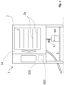
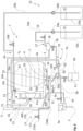
- the first cooking chamber outlet 4 is positioned centrally with respect to overlying trays or racks 2b, so as to effectively receive grease dripping from the foodstuff positioned on these trays or racks 2b.
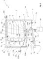
- the cooking oven 1 comprises a vapour outlet duct 9 configured for discharging vapour from the cooking chamber 2; the vapour outlet duct 9 can advantageously discharge the vapour in the external environment around the cooking oven 1, or it can be advantageously connected to a vapour discharge system, preferably provided in the building where the cooking oven 1 is installed.
- a washing liquid can be for example water and/or water containing a detergent
- a rinsing liquid can be, for example water and/or water containing a descaling additive or a brightener.
- a vortex preventing device 100 is positioned also at the second cooking chamber outlet 10.
- the cooking oven 1 comprises an oven outlet 5, configured for draining liquid outside the cooking oven 1; advantageously the oven outlet 5 can be connected to the sewage pipes, not illustrated, of the building in which the cooking oven 1 is installed.
- the first cooking chamber outlet 4 is fluidly connected, in addition to the grease conduit 6, also, preferably selectively, to the oven outlet 5.
- the oven outlet 5 is provided with an air trap 5a, for preventing, when active (i.e. when filled with a liquid), gas to exit through said oven outlet 5.
- the first cooking chamber outlet 4 can be fluidly connected to the circulation system 7.
- the second cooking chamber outlet 10 is fluidly connected, in addition to the vapour outlet duct 9, to the oven outlet 5.
- the first cooking chamber outlet 4 and the second cooking chamber outlet 10 are selectively connected to the oven outlet 5 via a second valve 12, which can be manual or automatic.
- the cooking oven 1 comprises a drain conduit 5b fluidly connecting the oven outlet 5 to the first cooking chamber outlet 4 and, preferably, to the second cooking chamber outlet 10.
- drain conduit 5b is fluidly connected to the oven outlet 5 via the second valve 12.
- the by-pass conduit 14 is fluidly connected to the grease conduit 6.
- the washing/rinsing liquid circulation outlet 13 and the outlet 16c of the introduction conduit 16a are positioned in an upper wall 23 of the cooking chamber 2.
- the washing/rinsing liquid circulation outlet 13 and the outlet 16c of the introduction conduit 16a are positioned in an upper wall 23 of the cooking chamber 2, in proximity of the suction wall 18.
- the outlet 16c of the introduction conduit 16a is separated from the washing/rinsing liquid circulation outlet 3.
- the outlet of the introduction conduit 16a into the cooking chamber 2 coincides with the washing/rinsing liquid circulation outlet 13.
- the cooking oven 1 comprises a quenching system 17 for cooling down steam exiting from the cooking chamber 2.
- the quenching system 17 comprises a quenching conduit 17a for supplying a cooling liquid within the vapour outlet duct 9.
- the quenching liquid is preferably fresh water, coming from the water mains, not illustrated, of the building in which the cooking oven 1 is installed, to which the quenching conduit 17a can be fluidly connected.
- the quenching conduit 17a comprises an inlet 170a positioned, in the operative position of the cooking oven 1, at a higher level with respect to the maximum level 500 that washing/rinsing liquid can reach within the cooking chamber 2 during the washing procedure of the cooking oven 1.
- the vapour outlet duct 9 comprises a bottom region 9a, positioned, in the operative position of the cooking oven 1, at least partially below the cooking chamber 2, and fluidly connected downstream of said second cooking chamber outlet 10.
- the bottom region 9a of the vapour outlet duct 9 is slightly inclined in such a way that liquid contained therein tends to flow, by gravity, in counter-current with respect to the vapour flowing through the bottom region 9a; in other words, the bottom region 9a is preferably inclined in such a way to define a backwards slope.
- the by-pass conduit 14 is connected to the vapour outlet duct 9 at or in proximity to the initial region of the bottom region 9a so that, due to the slope of the latter, condensed liquid present in such a bottom region 9a flows by gravity into the by-pass conduit 14.
- the end region 9b is substantially vertical.
- the quenching conduit 17a comprises an outlet 1710b positioned within the bottom region 9a of the vapour outlet duct 9; since in this way quenching liquid is released in the vapour outlet duct quite far away from its end region 9a, this arrangement of the outlet 170b prevents that quenching liquid (e.g. water) exiting the quenching conduit 17a is taken out of the vapour outlet duct 9 by the flow of vapour, schematically illustrated with dotted arrows 400 in attached figures, flowing therein.
- quenching liquid e.g. water
- the outlet 170b of the quenching conduit 17a can comprise a quenching nozzle, not illustrated, arranged within the bottom region 9a and configured for spraying a jet of water against the vapour exiting the cooking chamber outlet 10.
- the cooking oven 1 comprises a ventilation pipe 21 fluidly connected to the cooking chamber 2 and configured for selectively taking air from the external environment into the cooking chamber 2.
- the ventilation pipe 21 comprises an air inlet 21a provided at the heating chamber 19, more preferably in proximity to the fan 20.
- the ventilation pipe 21 is provided with a controlled ventilation valve 22 for selectively closing the ventilation pipe 21.
- the cooking oven 1 comprises an overflow conduit 26 directly fluidly connecting the vapour outlet duct 9 to the oven outlet 5, and configured for directly discharging to the oven outlet 5 liquid present in the vapour outlet duct 9 only if the level of such a liquid exceeds a certain height.
- such height corresponds to the maximum level 500 allowed for the liquid within the cooking chamber 2.
- the circulation system 7 is fluidly connected to the vapour outlet duct 9, and it is configured for taking washing/rinsing liquid from the cooking chamber 2 into the vapour outlet duct 9, so as to wash the latter.
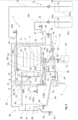
- the cleaning system 70 comprises a washing/rinsing additive supplying system 27 configured for supplying washing and/or rinsing additives to the internal of the cooking chamber 2.
- the washing/rinsing additive supplying system 27 comprises an additive drawer 28, loadable with a washing/rinsing additive, and selectively fluidly connected or connectable to the circulation system 7, in such a way to selectively supply a washing and/or rinsing additive into the latter, and preferably to the aspiration conduit 7b and/or delivery conduit 7c.
- the cooking oven 1 comprises a fifth valve 29 for connecting the additive drawer 28 to water supply mains.
- the cooking oven 1 comprises a sixth valve 30 selectively connecting the additive drawer 28 to the aspiration conduit 7b and/or delivery conduit 7c.
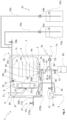
- the cleaning system 70 comprises a washing/rinsing additive multi-dosing system 31 configured for supplying to the internal of the cooking chamber 2 metered amounts of washing and/or rinsing additives.
- the washing/rinsing additive multi-dosing system 31 comprises:
- At least one of the one or more washing/rinsing additives containers 32a, 32b is fluidly connected to the washing/rinsing liquid introduction system 16, preferably to the introduction conduit 16a.
- all the washing/rinsing additives containers 32a, 32b are fluidly connected to the introduction conduit 16a; in this case, the drawer 28 is preferably not provided, and the cleaning system 70 can be used only as a "multi-dose" system.
- the cooking oven 1 comprises a steam supply system 35 configured for producing and supplying steam into the cooking chamber 2.
- the steam supply system 35 can comprise a boiler 36 configured for producing steam and fluidly connected to the cooking chamber 2 so as to release into the latter the steam.
- the boiler 36 comprises a water reservoir 37 fillable with water, and a water heater 38 for heating water loaded within the water reservoir 37.
- the cleaning system 70 is configured for supplying a washing/rinsing liquid to the boiler 36.
- the automatic or semi-automatic cleaning process advantageously starts with a washing phase, in which, in the embodiment of figure 2 , after having emptied the cooking chamber 2 and having positioned a detergent, for example in form of a tablet or of powder, in the bottom 3 of the cooking chamber, the door 2a can be closed, and, with the second valve 12 and the first valve 11 closed, third valve 16b can be opened (preferably automatically by the electronic controller 600).
- a washing phase in which, in the embodiment of figure 2 , after having emptied the cooking chamber 2 and having positioned a detergent, for example in form of a tablet or of powder, in the bottom 3 of the cooking chamber, the door 2a can be closed, and, with the second valve 12 and the first valve 11 closed, third valve 16b can be opened (preferably automatically by the electronic controller 600).
- the automatic or semi-automatic cleaning process advantageously comprises a rinsing phase in which, after closing the second valve 12 (which can be done automatically by the electronic controller 600), third valve 16b is opened again (preferably automatically by the electronic controller 600), so as to take clean water within the cooking chamber 2.
- third valve 16b is closed again (advantageously automatically by the electronic controller 600).
- the automatic or semi-automatic cleaning process advantageously comprises a steam supply system descaling phase, in which the water reservoir 37 of the steam supply system 35 is preferably emptied by opening the eight valve 42, and a descaling additive is loaded in the additive drawer 28.
- the fifth valve 29 is opened (preferably automatically by the electronic controller 600), so that clean water enters the additive drawer 28, dissolves, preferably only partially, the descaling additive contained therein, forming a descaling solution (i.e. water and descaling additive) which is taken, due to the pressure of the water in the water mains, into the water reservoir 37 through the boiler cleaning duct 44.
- a descaling solution i.e. water and descaling additive
- the water reservoir is only partially filled with the descaling solution coming from the drawer 28, since a part of the descaling additive should preferably remain in the additive drawer for being used in a further step of the automatic or semi-automatic cleaning process.
- the amount of water loaded into the water reservoir is controlled by a flowmeter, not illustrated, provided at or in series with the fifth valve 29, and preferably controlled by the electronic controller 600 in such a way to close the valve after a prefixed amount of water has flown into the additive drawer 28.
- the electronic controller 600 is also preferably configured in such a way that, in addition or in alternative to the flowmeter, a time-based control of the opening of the fifth valve 29 is performed; in other words, the valve is closed after a certain prefixed time has lapsed until its opening.
- some further water is loaded into the water reservoir 37 by opening (preferably automatically by the electronic controller 600) the seventh valve 41, until a prefixed level within the reservoir 37 is reached, and/or a prefixed time has lapsed until the opening of such seventh valve 41.
- a prefixed concentration of descaling additive in the descaling solution contained in the water reservoir is obtained.
- the seventh valve 41 is closed.
- the water heater 38 is switched on (preferably automatically by the electronic controller 600), so as to increase the descaling effect.
- the automatic or semi-automatic cleaning process comprises also a washing phase in which, after having emptied the cooking chamber 2 a detergent, for example in form of a tablet or of powder, is placed in the bottom 3 of the cooking chamber, and the door 2a can be closed.
- a detergent for example in form of a tablet or of powder
- third valve 16b can be opened (preferably automatically by the electronic controller 600).
- the liquid level within the cooking chamber 2 is preferably detected, for example by a suitable level sensor, not illustrated, present within the cooking chamber 2, and/or by a flowmeter, not illustrated measuring the amount of water entering through the third valve 16b, and communicating this amount to the electronic controller 600, which is configured for calculating the liquid level from the amount of liquid entering through the third valve 16b.
- The, circulation pump 7a is operated, so as to circulate the washing liquid (i.e. water mixed with the detergent present in the cooking chamber 2) through the circulation system 7.
- the washing liquid i.e. water mixed with the detergent present in the cooking chamber 2
- circulation pump 7a is operated, so as to circulate the clean water through the circulation system 7, so as to remove residuals of detergent possibly remained therein.
- circulation pump 7a is stopped, and the second valve 12 is opened (preferably automatically by the electronic controller 600), so as to drain the water, advantageously by gravity, through the oven outlet 5.
- One or more further rinsing phases can be performed.
- a descaling phase is advantageously performed.
- fifth valve 29 is opened (preferably automatically by the electronic controller 600), so that clean water enters the additive drawer 28, dissolves, preferably completely, the descaling additive contained therein, forming a descaling solution (i.e. water and descaling additive), and goes by gravity through sixth valve 30, to the aspiration conduit 7b.
- a descaling solution i.e. water and descaling additive
- the amount of water loaded into the water reservoir is controlled by a flowmeter, not illustrated, provided at or in series with the fifth valve 29, and preferably controlled by the electronic controller 600 in such a way to close the valve after a prefixed amount of water has flown into the additive drawer 28.
- the electronic controller 600 is also preferably configured in such a way that, in addition or in alternative to the flowmeter, a time-based control of the opening of the fifth valve 29 is performed; in other words, the valve is closed after a certain prefixed time has lapsed until its opening.
- circulation pump 7a is advantageously operated, so as to circulate the descaling liquid (i.e. water mixed with the descaling additive present in the additive drawer 28) through the circulation system 7.
- descaling liquid i.e. water mixed with the descaling additive present in the additive drawer 28
- the descaling liquid is circulated through the first cooking chamber outlet 4, grease conduit 6, connection duct 50, drain conduit 5b, second cooking chamber outlet 10, bottom region 9a and part of the end region 9b of the vapour outlet duct 9, by-pass conduit 14, aspiration duct 7b, delivery duct 7c, circulation outlet 13, cooking chamber 2.
- the heating device 8 is operated, so as to improve the descaling effect of the descaling liquid.
- the fan 20 is operated, so as to distribute the descaling liquid falling from the circulation outlet 13 on all the surfaces internal to the cooking chamber 2.
- circulation pump 7a is stopped, and the second valve 12 is opened (preferably automatically by the electronic controller 600), so as to drain the descaling liquid, advantageously by gravity, through the oven outlet 5.
- the steam supply system descaling phase can be completed; in this case, preferably automatically by the electronic controller 600, water heater 38 is switched off, eight valve 42 is opened, and the descaling solution present in the water reservoir 37 drained, advantageously by gravity, through the oven outlet 5.
- the automatic or semi-automatic cleaning process advantageously comprises a steam supply system rinsing phase, comprising closing the eight valve 42 and opening the seventh valve 41 for a prefixed time, and/or until a prefixed water level is reached within the water reservoir, so as to load clean water within the water reservoir 37, and finally, after a prefixed time has lapsed, opening the eight valve 42, so as to drain, by gravity, rinsing water via the oven outlet 5.
- a steam supply system rinsing phase comprising closing the eight valve 42 and opening the seventh valve 41 for a prefixed time, and/or until a prefixed water level is reached within the water reservoir, so as to load clean water within the water reservoir 37, and finally, after a prefixed time has lapsed, opening the eight valve 42, so as to drain, by gravity, rinsing water via the oven outlet 5.
- the automatic or semi-automatic cleaning process can comprise, before the washing phase, a soaking phase; preferably, in the soaking phase, with the second valve 12 and the first valve 11 closed, third valve 16b can be opened (preferably automatically by the electronic controller 600), preferably until a prefixed water level is reached within the cooking chamber 2, and/or a prefixed time has lapsed until the third valve 16b has been opened.
- heating device 8 is switched on, so as to heat the water collected in the bottom 3 of the cooking chamber 2; then, after a certain time has lapsed, the second valve 12 is opened, and soaking water is drained via the oven drain 5. Then the washing phase can be performed.
- the amount of descaling additive supplied to the additive drawer 28 can be advantageously controlled by operating the additive pump 34a for a prefixed time, and/or by measuring the amount of liquid flowing through additive delivery conduit 33a, for example by a flowmeter, not illustrated.
- the amount of washing agent supplied to the introduction system 16 is controlled by operating the additive pump 34b for a prefixed time, and/or by measuring the amount of liquid flowing through additive delivery conduit 33b, for example by a flowmeter, not illustrated.
- the embodiment of figure 4 allows loading also manually an additive into the additive drawer 28 (for example if the additive container 32a is empty, and/or for adding a further kind of additive in addition to the one contained in additive container 32a).
- the embodiment of figure 5 its functioning differs from the above described functioning of the embodiment of figure 1 only because:
- the amount of washing agent supplied to the introduction system 16 is controlled by operating the additive pump 34b for a prefixed time, and/or by measuring the amount of liquid flowing through additive delivery conduit 33b, for example by a flowmeter, not illustrated.
- the amount of descaling additive supplied to the additive drawer 28 can be advantageously controlled by operating the additive pump 34a for a prefixed time, and/or by measuring the amount of liquid flowing through additive delivery conduit 33a, for example by a flowmeter, not illustrated.
- the amount of washing agent supplied to the introduction system 16 is controlled by operating the additive pump 34b for a prefixed time, and/or by measuring the amount of liquid flowing through additive delivery conduit 33b, for example by a flowmeter, not illustrated.
- the embodiment of figure 6 allows loading also manually an additive into the additive drawer 28 (for example if the additive container 32a is empty, and/or for adding a further kind of additive in addition to the one contained in additive container 32a). It is seen therefore how the invention achieves the proposed aim and objects, there being provided a cooking oven which, thanks to two distinct cooking chamber outlets, one taking to the grease conduit, and the other to the vapour outlet duct, the risk that grease dripping from the foodstuff and collected in the bottom wall of the cooking chamber can obstruct or clog the vapour outlet duct, and the related above mentioned problems, is highly reduced.
- the two cooking chamber outlets are positioned in a region of the cooking chamber, i.e. its bottom wall, in which they don't hinder the circulation of air within the cooking chamber, and therefore they don't affect, or only marginally affect, the thermal uniformity within the cooking chamber.
Landscapes
- Engineering & Computer Science (AREA)
- Chemical & Material Sciences (AREA)
- Combustion & Propulsion (AREA)
- Mechanical Engineering (AREA)
- General Engineering & Computer Science (AREA)
- Chemical Kinetics & Catalysis (AREA)
- Food-Manufacturing Devices (AREA)
Claims (14)
- Garofen (1) für Lebensmittel, umfassend:- einen Garraum (2), in den Lebensmittel zum Garen eingelegt werden können, der eine Bodenwand (3) aufweist, die mit einem ersten Garraumauslass (4) bereitgestellt ist, der so angeordnet ist, dass er in der Bodenwand (3) gesammeltes Fett aufnimmt;- eine Fettleitung (6), die zum Ableiten von Fett aus dem Garraum (2) konfiguriert ist;wobei der erste Garraumauslass (4) mit der Fettleitung (6) fluidverbunden ist,wobei der Garofen ferner Folgendes umfasst:dadurch gekennzeichnet, dass- eine Heizvorrichtung (8), die zum Heizen des Inneren des Garraums (2) konfiguriert ist,- ein Dampfauslasskanal (9), der zum Ablassen von Dampf aus dem Garraum (2) konfiguriert ist,die Bodenwand (3) des Garraums (2) mit einem zweiten Garraumauslass (10) bereitgestellt ist, der sich von dem ersten Garraumauslass (4) unterscheidet und mit dem Dampfauslasskanal (9) fluidverbunden ist, undwobei der Einlassrand (10a) des zweiten Garraumauslasses (10) in einer erhöhten Position in Bezug auf den Einlassrand (4a) des ersten Garraumauslasses (4) angeordnet ist.
- Garofen (1) nach Anspruch 1, wobei der erste Garraumauslass (4) und der zweite Garraumauslass (10) so wechselseitig positioniert und/oder angeordnet sind, dass das in der Bodenwand (3) gesammelte Fett zuerst/leichter in den ersten Garraumauslass (4) als in den zweiten Garraumauslass (10) eintritt.
- Garofen (1) nach Anspruch 1 oder 2, wobei die Bodenwand (3a) des Garraums (2) mindestens teilweise trichterförmig ist, mindestens an oder in der Nähe des Einlassrandes (4a) des ersten Garraumauslasses (4).
- Garofen (1) nach einem oder mehreren der vorhergehenden Ansprüche, wobei der zweite Garraumauslass (10) zusätzlich zu dem Dampfauslasskanal (9) mit der Fettleitung (6) fluidverbunden ist.
- Garofen (1) nach Anspruch 4, wobei der zweite Garraumauslass (10) mit der Fettleitung (6) über einen Verbindungskanal (50) fluidverbunden ist, dessen Endabschnitt (50a) in die Fettleitung (6) im Wesentlichen senkrecht zu deren Innenfläche derselben hineinragt.
- Garofen (1) nach einem oder mehreren der vorhergehenden Ansprüche, umfassend ein Reinigungssystem (70), umfassend ein Zirkulationssystem (7), das zum Pumpen von Flüssigkeit aus dem Garraum (2) und zum erneuten Pumpen dieser Flüssigkeit oder eines Teils davon in den Garraum (2) konfiguriert ist.
- Garofen (1) nach Anspruch 6, wobei der erste Garraumauslass (4) zusätzlich zu der Fettleitung (6) mit dem Zirkulationssystem (7) fluidverbunden ist.
- Garofen (1) nach Anspruch 6 oder 7, wobei der zweite Garraumauslass (10) zusätzlich zu dem Dampfauslasskanal (9) mit dem Zirkulationssystem (7) fluidverbunden ist.
- Garofen (1) nach einem oder mehreren der Ansprüche 6 bis 8, wobei das Zirkulationssystem (7) eine Zirkulationspumpe (7a) umfasst, eine Ansaugleitung (7b), die die Zirkulationspumpe (7a) mit dem ersten Garraumauslass (4) und/oder dem zweiten Garraumauslass (10) verbindet und eine Zufuhrleitung (7c), die die Umwälzpumpe (7a) mit einem Wasch-/Spülflüssigkeits-Zirkulationsauslass (13) verbindet, der in dem Garraum (2) bereitgestellt und zum Ermöglichen des Eintretens von Wasch-/Spülflüssigkeit in den Garraum (2) konfiguriert ist.
- Garofen (1) nach einem oder mehreren der Ansprüche 6 bis 9, wobei das Reinigungssystem (70) ein Wasch-/Spülflüssigkeits-Einführsystem (16) umfasst, das zum Aufnehmen von Wasch-/Spülflüssigkeit innerhalb des Garraums (2) konfiguriert ist, wobei das Wasch-/Spülflüssigkeits-Einführsystem (16) eine Einführleitung (16a) umfasst, die mit dem Garraum (2) fluidverbunden ist und zum selektiven Zuführen von Wasch- und/oder Spülflüssigkeit in dieselbe konfiguriert ist.
- Garofen (1) nach Anspruch 10, wenn abhängig von Anspruch 9, wobei der Auslass (16c) der Einführleitung (16a) von dem Wasch-/Spülflüssigkeits-Zirkulationsauslass (13) getrennt ist, oder wobei der Auslass der Einführleitung (16a) in den Garraum (2) mit dem Wasch-/Spülflüssigkeits-Zirkulationsauslass (13) zusammenfällt.
- Garofen (1) nach einem oder mehreren der Ansprüche 7 bis 11, wobei die Ansaugleitung (7b) mit dem zweiten Garraumauslass (10) über eine Bypassleitung (14) fluidverbunden ist, die die Ansaugleitung (7b) mit dem Dampfauslasskanal (9) fluidverbindet, mit dem der zweite Garraumauslass (10) fluidverbunden ist.
- Garofen (1) nach einem oder mehreren der vorhergehenden Ansprüche, wobei das Reinigungssystem (70) ein Wasch-/Spülzusatz-Zufuhrsystem (27) umfasst, das zum Zuführen von Wasch- und/oder Spülzusätzen in das Innere des Garraums (2) konfiguriert ist, und/oder ein Wasch-/Spülzusatz-Mehrfachdosiersystem (31) umfasst, das zum Zuführen dosierter Mengen von Wasch- und/oder Spülzusätzen in das Innere des Garraums (2) konfiguriert ist.
- Garofen (1) nach einem oder mehreren der vorhergehenden Ansprüche, umfassend ein Dampfzufuhrsystem (35), das zum Erzeugen und Zuführen von Dampf in den Garraum (2) konfiguriert ist, wobei das Reinigungssystem (70) zum Zuführen einer Wasch-/Spülflüssigkeit an das Dampfzufuhrsystem (35) konfiguriert ist.
Priority Applications (3)
| Application Number | Priority Date | Filing Date | Title |
|---|---|---|---|
| EP19159483.7A EP3702675B1 (de) | 2019-02-26 | 2019-02-26 | Ofen zum kochen von lebensmitteln |
| PCT/EP2020/054692 WO2020173841A1 (en) | 2019-02-26 | 2020-02-21 | Cooking oven with steam generator |
| US17/422,055 US12181155B2 (en) | 2019-02-26 | 2020-02-21 | Cooking oven with steam generator |
Applications Claiming Priority (1)
| Application Number | Priority Date | Filing Date | Title |
|---|---|---|---|
| EP19159483.7A EP3702675B1 (de) | 2019-02-26 | 2019-02-26 | Ofen zum kochen von lebensmitteln |
Publications (2)
| Publication Number | Publication Date |
|---|---|
| EP3702675A1 EP3702675A1 (de) | 2020-09-02 |
| EP3702675B1 true EP3702675B1 (de) | 2024-07-10 |
Family
ID=65598569
Family Applications (1)
| Application Number | Title | Priority Date | Filing Date |
|---|---|---|---|
| EP19159483.7A Active EP3702675B1 (de) | 2019-02-26 | 2019-02-26 | Ofen zum kochen von lebensmitteln |
Country Status (1)
| Country | Link |
|---|---|
| EP (1) | EP3702675B1 (de) |
Families Citing this family (2)
| Publication number | Priority date | Publication date | Assignee | Title |
|---|---|---|---|---|
| KR102440813B1 (ko) * | 2022-02-04 | 2022-09-06 | 주식회사 동방포쎄 | 순환세척기능을 갖는 스팀 컨벡션 오븐 |
| US11882961B1 (en) | 2023-01-18 | 2024-01-30 | Sharkninja Operating Llc | Cover plate for cooking devices |
Family Cites Families (7)
| Publication number | Priority date | Publication date | Assignee | Title |
|---|---|---|---|---|
| IT1234689B (it) * | 1989-03-21 | 1992-05-26 | Zanussi Grandi Impianti Spa | Forno di cottura a convezione forzata |
| DE4225696A1 (de) * | 1992-08-04 | 1994-02-10 | Wiesheu Gmbh | Gerät für die Wärmebehandlung von Nahrungsmitteln |
| US6213002B1 (en) * | 1999-11-12 | 2001-04-10 | Thermaco, Inc. | Cooking apparatus with grease removal system |
| EP3134683B1 (de) * | 2014-04-22 | 2019-01-09 | Illinois Tool Works Inc. | Ofen mit wasser-dampf-trennung und verfahren zur verwendung dieses ofens |
| US10531760B2 (en) * | 2014-10-03 | 2020-01-14 | Convotherm Elektrogerate Gmbh | Method and apparatus for grease separation during a cooking cycle |
| US20160157658A1 (en) * | 2014-12-05 | 2016-06-09 | Timothy L. Cupp | Steam cooking oven and method |
| NL2017410B1 (en) * | 2016-09-02 | 2018-03-09 | Fri Jado Bv | System comprising a self-cleaning oven, and method for cleaning a self-cleaning oven |
-
2019
- 2019-02-26 EP EP19159483.7A patent/EP3702675B1/de active Active
Also Published As
| Publication number | Publication date |
|---|---|
| EP3702675A1 (de) | 2020-09-02 |
Similar Documents
| Publication | Publication Date | Title |
|---|---|---|
| US12181155B2 (en) | Cooking oven with steam generator | |
| RU2698745C1 (ru) | Устройство и способ приготовления пищевых ингредиентов за счет горячего воздуха и текучей среды, подаваемой в него | |
| EP3702676A1 (de) | Verfahren zur automatischen oder halbautomatischen reinigung eines garofens | |
| US6827004B2 (en) | Drip coffee maker with horizontal spray shower head | |
| US20080223357A1 (en) | Self-cleaning cooking appliance | |
| JP7174582B2 (ja) | 調理庫の洗浄機能付き加熱調理器 | |
| KR101296777B1 (ko) | 이중 오버플로우관을 갖는 스팀 컨벡션 오븐용 청소용수 저장탱크 | |
| ES3037965T3 (en) | Rotisserie oven | |
| US7677239B2 (en) | Kitchen-range, an oven and a self-cleaning assembly | |
| US20240011642A1 (en) | Device for treating vapors | |
| EP3702675A1 (de) | Ofen zum kochen von lebensmitteln | |
| US20200408441A1 (en) | Table fan and method for cleaning a table fan | |
| EP1978309A1 (de) | Selbstreinigende Kochvorrichtung | |
| EP3702678B1 (de) | Backofen mit einem automatischen oder halbautomatischen reinigungssystem | |
| WO2005090867A1 (ja) | 蒸気調理器 | |
| EP3702679B1 (de) | Garofen mit einem reinigungssystem | |
| JP2021196090A (ja) | 加熱調理器 | |
| CN116322459B (zh) | 具有至少一个空气出口的家用洗碗机 | |
| EP3702680A1 (de) | Garofen mit einem reinigungssystem | |
| JP7004602B2 (ja) | 食器洗浄機 | |
| WO2004088208A1 (en) | A kitchen-range, an oven and a self-cleaning assembly | |
| JP7115865B2 (ja) | 加熱調理器 | |
| JP7222826B2 (ja) | 加熱調理器 | |
| EP3683504B1 (de) | Ofen mit system zum dispergieren von chemischen mitteln | |
| EP3702677B1 (de) | Gargerät mit dampferzeuger und reinigungssystem |
Legal Events
| Date | Code | Title | Description |
|---|---|---|---|
| PUAI | Public reference made under article 153(3) epc to a published international application that has entered the european phase |
Free format text: ORIGINAL CODE: 0009012 |
|
| STAA | Information on the status of an ep patent application or granted ep patent |
Free format text: STATUS: THE APPLICATION HAS BEEN PUBLISHED |
|
| AK | Designated contracting states |
Kind code of ref document: A1 Designated state(s): AL AT BE BG CH CY CZ DE DK EE ES FI FR GB GR HR HU IE IS IT LI LT LU LV MC MK MT NL NO PL PT RO RS SE SI SK SM TR |
|
| AX | Request for extension of the european patent |
Extension state: BA ME |
|
| STAA | Information on the status of an ep patent application or granted ep patent |
Free format text: STATUS: REQUEST FOR EXAMINATION WAS MADE |
|
| 17P | Request for examination filed |
Effective date: 20210301 |
|
| RBV | Designated contracting states (corrected) |
Designated state(s): AL AT BE BG CH CY CZ DE DK EE ES FI FR GB GR HR HU IE IS IT LI LT LU LV MC MK MT NL NO PL PT RO RS SE SI SK SM TR |
|
| STAA | Information on the status of an ep patent application or granted ep patent |
Free format text: STATUS: EXAMINATION IS IN PROGRESS |
|
| 17Q | First examination report despatched |
Effective date: 20220914 |
|
| GRAP | Despatch of communication of intention to grant a patent |
Free format text: ORIGINAL CODE: EPIDOSNIGR1 |
|
| STAA | Information on the status of an ep patent application or granted ep patent |
Free format text: STATUS: GRANT OF PATENT IS INTENDED |
|
| INTG | Intention to grant announced |
Effective date: 20240318 |
|
| GRAS | Grant fee paid |
Free format text: ORIGINAL CODE: EPIDOSNIGR3 |
|
| GRAA | (expected) grant |
Free format text: ORIGINAL CODE: 0009210 |
|
| STAA | Information on the status of an ep patent application or granted ep patent |
Free format text: STATUS: THE PATENT HAS BEEN GRANTED |
|
| AK | Designated contracting states |
Kind code of ref document: B1 Designated state(s): AL AT BE BG CH CY CZ DE DK EE ES FI FR GB GR HR HU IE IS IT LI LT LU LV MC MK MT NL NO PL PT RO RS SE SI SK SM TR |
|
| REG | Reference to a national code |
Ref country code: CH Ref legal event code: EP |
|
| REG | Reference to a national code |
Ref country code: DE Ref legal event code: R096 Ref document number: 602019054868 Country of ref document: DE |
|
| P01 | Opt-out of the competence of the unified patent court (upc) registered |
Free format text: CASE NUMBER: APP_38798/2024 Effective date: 20240628 |
|
| REG | Reference to a national code |
Ref country code: LT Ref legal event code: MG9D |
|
| REG | Reference to a national code |
Ref country code: NL Ref legal event code: MP Effective date: 20240710 |
|
| PG25 | Lapsed in a contracting state [announced via postgrant information from national office to epo] |
Ref country code: PT Free format text: LAPSE BECAUSE OF FAILURE TO SUBMIT A TRANSLATION OF THE DESCRIPTION OR TO PAY THE FEE WITHIN THE PRESCRIBED TIME-LIMIT Effective date: 20241111 |
|
| REG | Reference to a national code |
Ref country code: AT Ref legal event code: MK05 Ref document number: 1702319 Country of ref document: AT Kind code of ref document: T Effective date: 20240710 |
|
| PG25 | Lapsed in a contracting state [announced via postgrant information from national office to epo] |
Ref country code: NL Free format text: LAPSE BECAUSE OF FAILURE TO SUBMIT A TRANSLATION OF THE DESCRIPTION OR TO PAY THE FEE WITHIN THE PRESCRIBED TIME-LIMIT Effective date: 20240710 |
|
| PG25 | Lapsed in a contracting state [announced via postgrant information from national office to epo] |
Ref country code: PT Free format text: LAPSE BECAUSE OF FAILURE TO SUBMIT A TRANSLATION OF THE DESCRIPTION OR TO PAY THE FEE WITHIN THE PRESCRIBED TIME-LIMIT Effective date: 20241111 Ref country code: NL Free format text: LAPSE BECAUSE OF FAILURE TO SUBMIT A TRANSLATION OF THE DESCRIPTION OR TO PAY THE FEE WITHIN THE PRESCRIBED TIME-LIMIT Effective date: 20240710 |
|
| PG25 | Lapsed in a contracting state [announced via postgrant information from national office to epo] |
Ref country code: NO Free format text: LAPSE BECAUSE OF FAILURE TO SUBMIT A TRANSLATION OF THE DESCRIPTION OR TO PAY THE FEE WITHIN THE PRESCRIBED TIME-LIMIT Effective date: 20241010 |
|
| PG25 | Lapsed in a contracting state [announced via postgrant information from national office to epo] |
Ref country code: FI Free format text: LAPSE BECAUSE OF FAILURE TO SUBMIT A TRANSLATION OF THE DESCRIPTION OR TO PAY THE FEE WITHIN THE PRESCRIBED TIME-LIMIT Effective date: 20240710 Ref country code: GR Free format text: LAPSE BECAUSE OF FAILURE TO SUBMIT A TRANSLATION OF THE DESCRIPTION OR TO PAY THE FEE WITHIN THE PRESCRIBED TIME-LIMIT Effective date: 20241011 Ref country code: PL Free format text: LAPSE BECAUSE OF FAILURE TO SUBMIT A TRANSLATION OF THE DESCRIPTION OR TO PAY THE FEE WITHIN THE PRESCRIBED TIME-LIMIT Effective date: 20240710 |
|
| PG25 | Lapsed in a contracting state [announced via postgrant information from national office to epo] |
Ref country code: BG Free format text: LAPSE BECAUSE OF FAILURE TO SUBMIT A TRANSLATION OF THE DESCRIPTION OR TO PAY THE FEE WITHIN THE PRESCRIBED TIME-LIMIT Effective date: 20240710 |
|
| PG25 | Lapsed in a contracting state [announced via postgrant information from national office to epo] |
Ref country code: LV Free format text: LAPSE BECAUSE OF FAILURE TO SUBMIT A TRANSLATION OF THE DESCRIPTION OR TO PAY THE FEE WITHIN THE PRESCRIBED TIME-LIMIT Effective date: 20240710 |
|
| PG25 | Lapsed in a contracting state [announced via postgrant information from national office to epo] |
Ref country code: AT Free format text: LAPSE BECAUSE OF FAILURE TO SUBMIT A TRANSLATION OF THE DESCRIPTION OR TO PAY THE FEE WITHIN THE PRESCRIBED TIME-LIMIT Effective date: 20240710 Ref country code: IS Free format text: LAPSE BECAUSE OF FAILURE TO SUBMIT A TRANSLATION OF THE DESCRIPTION OR TO PAY THE FEE WITHIN THE PRESCRIBED TIME-LIMIT Effective date: 20241110 |
|
| PG25 | Lapsed in a contracting state [announced via postgrant information from national office to epo] |
Ref country code: HR Free format text: LAPSE BECAUSE OF FAILURE TO SUBMIT A TRANSLATION OF THE DESCRIPTION OR TO PAY THE FEE WITHIN THE PRESCRIBED TIME-LIMIT Effective date: 20240710 |
|
| PG25 | Lapsed in a contracting state [announced via postgrant information from national office to epo] |
Ref country code: ES Free format text: LAPSE BECAUSE OF FAILURE TO SUBMIT A TRANSLATION OF THE DESCRIPTION OR TO PAY THE FEE WITHIN THE PRESCRIBED TIME-LIMIT Effective date: 20240710 Ref country code: RS Free format text: LAPSE BECAUSE OF FAILURE TO SUBMIT A TRANSLATION OF THE DESCRIPTION OR TO PAY THE FEE WITHIN THE PRESCRIBED TIME-LIMIT Effective date: 20241010 |
|
| PG25 | Lapsed in a contracting state [announced via postgrant information from national office to epo] |
Ref country code: RS Free format text: LAPSE BECAUSE OF FAILURE TO SUBMIT A TRANSLATION OF THE DESCRIPTION OR TO PAY THE FEE WITHIN THE PRESCRIBED TIME-LIMIT Effective date: 20241010 Ref country code: PL Free format text: LAPSE BECAUSE OF FAILURE TO SUBMIT A TRANSLATION OF THE DESCRIPTION OR TO PAY THE FEE WITHIN THE PRESCRIBED TIME-LIMIT Effective date: 20240710 Ref country code: NO Free format text: LAPSE BECAUSE OF FAILURE TO SUBMIT A TRANSLATION OF THE DESCRIPTION OR TO PAY THE FEE WITHIN THE PRESCRIBED TIME-LIMIT Effective date: 20241010 Ref country code: LV Free format text: LAPSE BECAUSE OF FAILURE TO SUBMIT A TRANSLATION OF THE DESCRIPTION OR TO PAY THE FEE WITHIN THE PRESCRIBED TIME-LIMIT Effective date: 20240710 Ref country code: IS Free format text: LAPSE BECAUSE OF FAILURE TO SUBMIT A TRANSLATION OF THE DESCRIPTION OR TO PAY THE FEE WITHIN THE PRESCRIBED TIME-LIMIT Effective date: 20241110 Ref country code: HR Free format text: LAPSE BECAUSE OF FAILURE TO SUBMIT A TRANSLATION OF THE DESCRIPTION OR TO PAY THE FEE WITHIN THE PRESCRIBED TIME-LIMIT Effective date: 20240710 Ref country code: GR Free format text: LAPSE BECAUSE OF FAILURE TO SUBMIT A TRANSLATION OF THE DESCRIPTION OR TO PAY THE FEE WITHIN THE PRESCRIBED TIME-LIMIT Effective date: 20241011 Ref country code: FI Free format text: LAPSE BECAUSE OF FAILURE TO SUBMIT A TRANSLATION OF THE DESCRIPTION OR TO PAY THE FEE WITHIN THE PRESCRIBED TIME-LIMIT Effective date: 20240710 Ref country code: ES Free format text: LAPSE BECAUSE OF FAILURE TO SUBMIT A TRANSLATION OF THE DESCRIPTION OR TO PAY THE FEE WITHIN THE PRESCRIBED TIME-LIMIT Effective date: 20240710 Ref country code: BG Free format text: LAPSE BECAUSE OF FAILURE TO SUBMIT A TRANSLATION OF THE DESCRIPTION OR TO PAY THE FEE WITHIN THE PRESCRIBED TIME-LIMIT Effective date: 20240710 Ref country code: AT Free format text: LAPSE BECAUSE OF FAILURE TO SUBMIT A TRANSLATION OF THE DESCRIPTION OR TO PAY THE FEE WITHIN THE PRESCRIBED TIME-LIMIT Effective date: 20240710 |
|
| REG | Reference to a national code |
Ref country code: DE Ref legal event code: R097 Ref document number: 602019054868 Country of ref document: DE |
|
| PG25 | Lapsed in a contracting state [announced via postgrant information from national office to epo] |
Ref country code: SM Free format text: LAPSE BECAUSE OF FAILURE TO SUBMIT A TRANSLATION OF THE DESCRIPTION OR TO PAY THE FEE WITHIN THE PRESCRIBED TIME-LIMIT Effective date: 20240710 Ref country code: RO Free format text: LAPSE BECAUSE OF FAILURE TO SUBMIT A TRANSLATION OF THE DESCRIPTION OR TO PAY THE FEE WITHIN THE PRESCRIBED TIME-LIMIT Effective date: 20240710 Ref country code: DK Free format text: LAPSE BECAUSE OF FAILURE TO SUBMIT A TRANSLATION OF THE DESCRIPTION OR TO PAY THE FEE WITHIN THE PRESCRIBED TIME-LIMIT Effective date: 20240710 |
|
| PG25 | Lapsed in a contracting state [announced via postgrant information from national office to epo] |
Ref country code: EE Free format text: LAPSE BECAUSE OF FAILURE TO SUBMIT A TRANSLATION OF THE DESCRIPTION OR TO PAY THE FEE WITHIN THE PRESCRIBED TIME-LIMIT Effective date: 20240710 |
|
| PG25 | Lapsed in a contracting state [announced via postgrant information from national office to epo] |
Ref country code: CZ Free format text: LAPSE BECAUSE OF FAILURE TO SUBMIT A TRANSLATION OF THE DESCRIPTION OR TO PAY THE FEE WITHIN THE PRESCRIBED TIME-LIMIT Effective date: 20240710 |
|
| PG25 | Lapsed in a contracting state [announced via postgrant information from national office to epo] |
Ref country code: SK Free format text: LAPSE BECAUSE OF FAILURE TO SUBMIT A TRANSLATION OF THE DESCRIPTION OR TO PAY THE FEE WITHIN THE PRESCRIBED TIME-LIMIT Effective date: 20240710 |
|
| PLBE | No opposition filed within time limit |
Free format text: ORIGINAL CODE: 0009261 |
|
| STAA | Information on the status of an ep patent application or granted ep patent |
Free format text: STATUS: NO OPPOSITION FILED WITHIN TIME LIMIT |
|
| 26N | No opposition filed |
Effective date: 20250411 |
|
| PG25 | Lapsed in a contracting state [announced via postgrant information from national office to epo] |
Ref country code: SE Free format text: LAPSE BECAUSE OF FAILURE TO SUBMIT A TRANSLATION OF THE DESCRIPTION OR TO PAY THE FEE WITHIN THE PRESCRIBED TIME-LIMIT Effective date: 20240710 |
|
| PG25 | Lapsed in a contracting state [announced via postgrant information from national office to epo] |
Ref country code: MC Free format text: LAPSE BECAUSE OF FAILURE TO SUBMIT A TRANSLATION OF THE DESCRIPTION OR TO PAY THE FEE WITHIN THE PRESCRIBED TIME-LIMIT Effective date: 20240710 |
|
| REG | Reference to a national code |
Ref country code: CH Ref legal event code: PL |
|
| PG25 | Lapsed in a contracting state [announced via postgrant information from national office to epo] |
Ref country code: LU Free format text: LAPSE BECAUSE OF NON-PAYMENT OF DUE FEES Effective date: 20250226 |
|
| PG25 | Lapsed in a contracting state [announced via postgrant information from national office to epo] |
Ref country code: CH Free format text: LAPSE BECAUSE OF NON-PAYMENT OF DUE FEES Effective date: 20250228 |
|
| GBPC | Gb: european patent ceased through non-payment of renewal fee |
Effective date: 20250226 |
|
| REG | Reference to a national code |
Ref country code: BE Ref legal event code: MM Effective date: 20250228 |
|
| PG25 | Lapsed in a contracting state [announced via postgrant information from national office to epo] |
Ref country code: GB Free format text: LAPSE BECAUSE OF NON-PAYMENT OF DUE FEES Effective date: 20250226 |
|
| PG25 | Lapsed in a contracting state [announced via postgrant information from national office to epo] |
Ref country code: FR Free format text: LAPSE BECAUSE OF NON-PAYMENT OF DUE FEES Effective date: 20250228 |
|
| PG25 | Lapsed in a contracting state [announced via postgrant information from national office to epo] |
Ref country code: BE Free format text: LAPSE BECAUSE OF NON-PAYMENT OF DUE FEES Effective date: 20250228 |
|
| PG25 | Lapsed in a contracting state [announced via postgrant information from national office to epo] |
Ref country code: IE Free format text: LAPSE BECAUSE OF NON-PAYMENT OF DUE FEES Effective date: 20250226 |
|
| PGFP | Annual fee paid to national office [announced via postgrant information from national office to epo] |
Ref country code: DE Payment date: 20260218 Year of fee payment: 8 |
|
| PGFP | Annual fee paid to national office [announced via postgrant information from national office to epo] |
Ref country code: IT Payment date: 20260115 Year of fee payment: 8 |