EP3702724A1 - Vorrichtung zum erfassen des profils einer reifenlauffläche und entsprechendes verfahren - Google Patents
Vorrichtung zum erfassen des profils einer reifenlauffläche und entsprechendes verfahren Download PDFInfo
- Publication number
- EP3702724A1 EP3702724A1 EP20155792.3A EP20155792A EP3702724A1 EP 3702724 A1 EP3702724 A1 EP 3702724A1 EP 20155792 A EP20155792 A EP 20155792A EP 3702724 A1 EP3702724 A1 EP 3702724A1
- Authority
- EP
- European Patent Office
- Prior art keywords
- tread
- light
- slit
- image
- light source
- Prior art date
- Legal status (The legal status is an assumption and is not a legal conclusion. Google has not performed a legal analysis and makes no representation as to the accuracy of the status listed.)
- Withdrawn
Links
- 238000001514 detection method Methods 0.000 title description 8
- 238000012545 processing Methods 0.000 claims abstract description 14
- 238000000034 method Methods 0.000 claims description 7
- 230000003213 activating effect Effects 0.000 claims description 2
- 238000001228 spectrum Methods 0.000 claims description 2
- 238000010586 diagram Methods 0.000 description 6
- 230000003287 optical effect Effects 0.000 description 5
- 238000005259 measurement Methods 0.000 description 4
- 230000003068 static effect Effects 0.000 description 4
- 230000006798 recombination Effects 0.000 description 3
- 238000005215 recombination Methods 0.000 description 3
- 239000000243 solution Substances 0.000 description 3
- 238000004364 calculation method Methods 0.000 description 2
- 238000004891 communication Methods 0.000 description 2
- 230000000694 effects Effects 0.000 description 2
- 238000012805 post-processing Methods 0.000 description 2
- 238000007781 pre-processing Methods 0.000 description 2
- 238000012360 testing method Methods 0.000 description 2
- 230000004913 activation Effects 0.000 description 1
- 230000003321 amplification Effects 0.000 description 1
- 230000005540 biological transmission Effects 0.000 description 1
- 230000015556 catabolic process Effects 0.000 description 1
- 239000003795 chemical substances by application Substances 0.000 description 1
- 238000010276 construction Methods 0.000 description 1
- 238000011109 contamination Methods 0.000 description 1
- 238000006731 degradation reaction Methods 0.000 description 1
- 230000000994 depressogenic effect Effects 0.000 description 1
- 238000005516 engineering process Methods 0.000 description 1
- 238000000605 extraction Methods 0.000 description 1
- 238000001746 injection moulding Methods 0.000 description 1
- 230000003993 interaction Effects 0.000 description 1
- 238000004519 manufacturing process Methods 0.000 description 1
- 239000000463 material Substances 0.000 description 1
- 239000000203 mixture Substances 0.000 description 1
- 238000003199 nucleic acid amplification method Methods 0.000 description 1
- 230000000737 periodic effect Effects 0.000 description 1
- 238000012546 transfer Methods 0.000 description 1
- 238000011144 upstream manufacturing Methods 0.000 description 1
Images


Classifications
-
- G—PHYSICS
- G01—MEASURING; TESTING
- G01B—MEASURING LENGTH, THICKNESS OR SIMILAR LINEAR DIMENSIONS; MEASURING ANGLES; MEASURING AREAS; MEASURING IRREGULARITIES OF SURFACES OR CONTOURS
- G01B11/00—Measuring arrangements characterised by the use of optical techniques
- G01B11/24—Measuring arrangements characterised by the use of optical techniques for measuring contours or curvatures
- G01B11/25—Measuring arrangements characterised by the use of optical techniques for measuring contours or curvatures by projecting a pattern, e.g. one or more lines, moiré fringes on the object
-
- G—PHYSICS
- G01—MEASURING; TESTING
- G01B—MEASURING LENGTH, THICKNESS OR SIMILAR LINEAR DIMENSIONS; MEASURING ANGLES; MEASURING AREAS; MEASURING IRREGULARITIES OF SURFACES OR CONTOURS
- G01B11/00—Measuring arrangements characterised by the use of optical techniques
- G01B11/22—Measuring arrangements characterised by the use of optical techniques for measuring depth
-
- G—PHYSICS
- G01—MEASURING; TESTING
- G01M—TESTING STATIC OR DYNAMIC BALANCE OF MACHINES OR STRUCTURES; TESTING OF STRUCTURES OR APPARATUS, NOT OTHERWISE PROVIDED FOR
- G01M17/00—Testing of vehicles
- G01M17/007—Wheeled or endless-tracked vehicles
- G01M17/02—Tyres
- G01M17/027—Tyres using light, e.g. infrared, ultraviolet or holographic techniques
Definitions
- the present invention relates to devices for detecting the profile of a tread, in particular a tread of a motor-vehicle tire.
- Detection of the profile of the tread of tires of a motor vehicle is required in certain jurisdictions as part of the activity of periodic ascertainment and check-up of motor vehicles in order to verify perfect efficiency thereof. Testing of tread wear is moreover useful for predicting the residual duration of the tire, and possibly for correcting the alignment of the wheels and in general the parameters of attitude of the vehicle.
- the profile of the tread of tires of a motor vehicle is preferentially measured using portable devices, via which the operator scans the surface of the tread that is to undergo testing.
- portable devices via which the operator scans the surface of the tread that is to undergo testing.
- devices There exist many types of devices, from the simplest (mechanical devices or contact devices, which measure one groove at a time) to the most complex, which use laser triangulations.
- the object of the present invention is to solve the technical problems mentioned previously.
- the object of the present invention is to provide a device for detecting the profile of a tread that will be inexpensive to produce, accurate in the measurement irrespective of the skill of the operator, and robust in regard to the environment in which it is to operate.
- the reference number 1 in Figure 1 designates as a whole a device for detecting a profile of a tread according to a first embodiment of the invention.
- the device 1 comprises a light source 2, a mask 4, at least one image-acquisition device 6, and a data-processing unit 8 operatively connected to the image-acquisition device 6.
- the processing unit may be incorporated in part or entirely within the device 1.
- the image-acquisition device is preferably provided as a video camera with an acquisition rate of between 12 fps and 60 fps, possibly controlled by means of an image pre-processing application or algorithm in order to enable real-time extraction of the fraction of interest of the image, eliminating the non-useful fraction.
- the light source 2 is preferably a light source with linear extension, which in this embodiment comprises a linear array of concentrated light sources 10, in particular light-emitting diodes (LEDs) with emission in the visible light spectrum.
- LEDs light-emitting diodes
- non-collimated or low-collimation laser diodes it is possible to use non-collimated or low-collimation laser diodes. The latter possibility is contemplated, for example but not exclusively, for embodiments of the device 1 (and in general of the device according to the invention), for the detection of the profile of a tread of a tire for aircraft (for example, for civil aircraft).
- each concentrated source 10 is associated to the reference L10, and, for convenience of representation, in Figure 1 it is represented as if it were sectioned in a plane.
- the light emission L10 has - in the case of a concentrated source corresponding to a light-emitting diode - the shape of an elliptical cone with vertex set in close proximity of the source itself.
- the source 2 whether single or made up of a plurality of concentrated sources, is a non-collimated light source.
- the mask 4 comprises a slit 12 with linear extension, with respect to which the source 2 extends in a parallel direction and - preferably - in a collinear position.
- the slit 12 is provided (as a through slit) in the mask 4 in such a way that, named W a width of the slit 12 and named D a depth of the slit 12, a ratio W/D is comprised between 0.05 and 1.
- the width W of the slit 12 is comprised between 0.1 mm and 0.4 mm, whereas the depth D of the slit 12 is generally comprised between 0.4 mm and 2 mm.
- this length - given the same ratio W/D - can vary on the basis of the embodiment of the device according to the invention and may, in particular, be chosen in such a way as to cover only a portion of the width of a motor-vehicle tread (with reference to the dimensions most widely encountered on the market or in any case to the requirements of the user, which may comprise also twin tires) or else may be sized in such a way as to extend along the entire transverse extension of the tread.
- a motor-vehicle tread with reference to the dimensions most widely encountered on the market or in any case to the requirements of the user, which may comprise also twin tires
- the latter is the case of Figure 3 , as will be described in detail hereinafter.
- the light source 2 is preferably positioned at a distance h from the level of the slit 12 that is comprised between 1 mm and 10 mm, preferably between 3 mm and 10 mm.
- the distance h is in general the distance between the surface of the mask 4 (in which the slit is obtained) exposed to the source 2 and the optical centre of the light source.
- Many light sources commonly available comprise - even when they are classified as non-collimated or low-collimation sources - an internal lens, so that the optical centre is evaluated in relation to the characteristics of the internal lens. On the hypothesis where the light source is without the internal lens, the optical centre is on the emitting surface.
- FIGS. 1A and 2 illustrate schematically a layout of the components of the device 1 within a casing 14 of a portable instrument.
- the casing 14 comprises a grip 16 (that can be oriented at least in two possible directions, one of which, the preferred one, is shown in Figure 1A , and the other is shown in Figure 2 ), and is preferably made up of a pair of shells of plastic material 18, 20 (or more than two shells, according to the constraints existing for production thereof by means of injection moulding or by means of forming of some other type).
- the shell 18 houses a transparent screen 22 permeable to the light emission L10 coming from the source 2 in order to protect the internal components of the device from contamination by external agents.
- the image-acquisition device 6 is set, with respect to the mask 4, in such a way that an optical axis ⁇ 6 thereof is inclined by an angle ⁇ with respect to a plane of reference ⁇ 4 parallel to the plane of the slit 12.
- the angle ⁇ is preferably comprised between 45° and 70° according to the need.
- the device 1 substantially assumes the form of a handheld device by means of which an operator can carry out a manual scan of a tread of a motor-vehicle tire.
- the global shape of the casing 14 of the device 1 may in any case vary according to the requirements, for example according to whether the device incorporates a screen or not, and/or also other components such as a video camera for photographing the vehicle or the numberplate thereof, or else again a barcode-reader device for detecting the chassis number of the vehicle.
- the light source 2 is configured for producing a non-collimated light emission, which, in the embodiment of Figure 1 , consists of a plurality of conical light emissions from each of the LEDs 10 (or of the concentrated sources) that impinge upon the mask 4.
- the mask 4 is permeable to the light emission of the source 2 only in correspondence of the slit 12.
- the slit 12 lets through only the fraction of light rays of the emission L10 around the axis of each concentrated source 10. This requires the slit 12 to be positioned so as to be traversed by the axes of the concentrated sources 10, and at a distance h such that the fraction of light emission L10 will comprise rays that are as parallel as possible.
- a slit 12 set almost up against the sources 10 would intercept only the portions of light emission L10 with a trajectory that is very angled with respect to the axis of the source 10; the rays that pass through the slit would still be too divergent.
- a slit 12 that is very far from the source would let through only rays very with low divergence (hence with a narrow angle with respect to the axis of the source 10), and would hence be ideal for the application; the problem would, however, be that the light power of this small number of rays would be an excessively small fraction of the total light power emitted.
- the distance h is hence chosen as a compromise, the target being to maintain a line of light on the object to be measured that is not excessively thick, but is also sufficiently sharp.
- the fraction of light emission L10 of the source 2 that travels through the slit 12 is identified by the reference LC*, and the sum of all the fractions LC* gives rise to a light curtain LC with characteristics at least roughly similar to those of a collimated light emission.
- an angle of aperture ⁇ of the fraction of light emission LC* is smaller than the angle of aperture ⁇ in any radial plane with respect to the axis of the elliptical cone that defines the light emission L10 upstream of the slit 12.
- the mask 4 replaces in a simple way the function of a collimator device, and in particular filters the global light emission of the source 2 letting through only the fraction necessary for creation of a curtain (or blade) of light that impinges upon the tire tread.
- the light curtain LC that comes out of the slit 12 impinges upon a tread TH of a motor-vehicle tire T, generating a projection P that extends in a direction transverse to the tread TH throughout the extension X12 of the slit 12.
- the slit 12 has a dimension X12 smaller than the width of the tread TH, so that it is necessary for the operator who carries out detection of the profile of the tread TH to perform a manual transverse scan from one end to the other of the tread TH, as indicated, by way of example, by the arrow SC of Figure 1 .
- the conformation of the casing 14 with a grip 16 facilitates this operation, but it should in any case be borne in mind that the casing 14 may assume other shapes, for example in the case where it incorporates a screen.
- the projection P of the light curtain LC on the tread TH takes the form of a line or band (according to the angle ⁇ ) that is fretted - on account of the presence of inevitable presence of grooves on the tread due to the tread pattern -, this line or band developing along the surface of the tread TH upon which the light curtain impinges.
- the projection P is then framed and acquired as complex of data by the image-acquisition device 6.
- the complex of data acquired by the device 6 comprises one set of frames for each position of the device 1 with respect to the tread TH resulting from manual scanning thereof, according to the acquisition rate of the video camera 6.
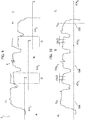
- Figures 9A-9C exemplify a set of frames acquired during a scan of the tread TH by means of the device 1.
- Each diagram shows - for convenience of representation - a single frame acquired at an instant in time (if the unit of time considered were the second, s, then the diagram should comprise k partially overlapping curves, where k is the number of frames per second - fps - that the device 6 is able to acquire).
- the total number of frames acquired is equal to the acquisition rate measured in fps multiplied by the total time of activation of the device 1 (it is assumed that the user activates the device at the start of scanning and deactivates it at the end, by means of one or more pushbuttons; e.g., a single pushbutton could be kept depressed during acquisition).
- the curves shown in Figures 9A-9C represent, net of the signal disturbance, the image of the projection P generated by the light curtain LC when it impinges upon on the tread TH, as acquired by the device 6.
- a portion of the profile of the tread is acquired, and the various portions are recombined in the data-postprocessing stage to return the image of the profile of the tread TH.
- the acquisitions at each instant exhibit a certain degree of overlapping with the acquisitions at the immediately previous and immediately subsequent instants: these overlapping portions are identified by the reference O and may reach - for each instant - a value of 50% of the acquisitions made at the previous instant and at the subsequent instant.
- the image-acquisition device 6 then transmits the data to the processing unit 8, which is configured for operative communication with an external computer CM, for example by means of the Bluetooth communication protocol or by means of some other type of radiofrequency transmission, on board which the operations of solution of the profile by composition of the images (frames) acquired by the video camera 6 during scanning are carried out.
- CM an external computer
- each frame may be preliminarily processed already on board the device 1 precisely via the unit 8, for example by means of an algorithm that amplifies in the image acquired the colour of the light emission of the source 10.
- the external computer CM is used only for projection of the data (image data and profile parameters) useful for the operator and/or for being filed.
- impinging upon the tread TH with the light curtain LC comprises scanning the tread TH in a transverse direction (i.e., in the direction of the width of the tread, parallel to the axis of rotation of the tire T) by means of the device 1 itself, in particular by means of the light curtain LC emitted through the slit 12.
- the reason for this procedure - as has been described - is that the slit 12 does not extend throughout the width of the tread TH.
- a second embodiment of the device according to the invention is identified by the reference number 100.
- the reference numbers that are identical to the ones already used for the device 1 designate the same components.
- the device 100 is built in an identical way as the device 1, except for the linear dimensions of the mask 4 and light source 2, and for the number of image-acquisition devices.
- the device 100 is configured for static operation; i.e., it does not require scanning of the surface of the tread TH by the operator.
- the mask 4 is replaced by a mask 104 provided with a slit 112 having an extension equal to or greater than a reference extension, which represents a maximum value of tread width for the tires in a given segment of sizes.
- the slit 112 is characterized by the same ranges of the ratio W/D already described in detail in relation to the mask 4.
- the arrangement of the components does not change as compared to the device 1; i.e., all the specifications in terms of relative positioning of the components (distance h, angle ⁇ ) already described can still be applied, in particular as regards the position of the light source 2 with respect to the mask 104.
- the device 100 comprises a greater number of image-acquisition devices 106, and in particular - in the embodiment shown here - instead of the single device 6 of Figure 1 , there are now three image-acquisition devices (preferably video cameras) arranged spaced apart in the main direction of extension of the slit 112.
- the number of devices 106 may be varied accordingly, from a minimum of two (if the device were single, the embodiment would correspond to that of Figures 1 and 2 ) to a maximum depending upon the largest tread width that is to be inspected. Also the desired resolution/measurement accuracy affects the number of video cameras.
- the device 100 can hence be provided in various versions that differ as regards the length of the slit 112 for corresponding tire ranges, where each version is configured for static scanning of a given range of tread widths, where each range may reflect a corresponding class of vehicles.
- Each device 100 conceived for a range of tires of larger size is able to scan statically also ones of smaller size, whereas the opposite does not apply.
- the device 100 In the case of operation in nominal conditions, i.e., with the device 100 used on a tread having a size compatible with the extension of the respective slit 112, the device 100 is kept stationary above the tread TH, while the latter is integrally impinged upon by a light curtain LC of amplitude equal to or greater than the transverse dimension thereof.
- FIGS 10A-10C exemplify a set of frames acquired during (static) scanning of the tread TH by means of the device 100.
- Each diagram shows - for convenience of illustration - a single frame acquired at the same instant in time (if the unit of time considered were the second, s, then the diagram would comprises k overlapping curves, where k is the number of frames per second, fps, that the device 106 is able to acquire). Since the projection P of the light curtain LC is framed simultaneously and integrally by all the video cameras 106, strictly speaking it is not necessary to acquire a large number of frames. Ideally, a double series of frames (for redundancy and coherence check) is already sufficient to determine the profile of the tread TH by recombination.
- the curves represented in Figures 10A-10C show, net of the signal disturbance, the image of the projection P generated by the light curtain LC when it impinges upon the tread TH, as acquired by each device 106.
- each device 106 acquires the portion of the profile of the tread TH within the respective field of vision (the fields of vision may preferably present overlapping areas), and the sets of images acquired at each instant are recombined in the data-postprocessing stage to yield the image of the profile of the tread TH.
- the overlaps are here associated to the references O1/2 and O2/3 (the figures refer to the reference systems of each video camera 106) and have a width smaller than that of the overlaps O that characterize the partial acquisitions of Figures 9A-9C .
- the data-processing unit 8 hence receives the frames acquired by each image-acquisition device 106 (possibly applying a pre-processing with amplification of the colour of the light emission of the source 2), and, as the sets of frames are sent to the external computer CM, they are recombined by the computer CM in such a way as to reconstruct the profile.
- the device 1 it is possible to equip the unit 8 with a microprocessor that will be able to carry out recombination of the data and calculation of the profile of the tread on board the instrument, and then send the results to the computer CM.
- the processing unit 8 (and/or the external computer CM) is configured for extracting the profile of the projection P, and then for carrying out linearization and for fitting the information associated to the projection P into known patterns. This is possible by preliminary calibration of the system, for example using calibration tables that associate to a given sample of acquisitions of projections P respective known patterns.
- the processing unit 8 and/or the computer CM compare/compares the image data corresponding to the projection P acquired via the video camera/cameras 6, 106 with the various reference samples, thus arriving (via the sample) at association of the image acquired to the corresponding (and effective) thread pattern.
- the method for detecting the profile of a tread that can be implemented by means of the device 100 is hence identical, in the general definition of the various steps, to the one already described for the device 1.
- the only difference lies in the fact that the step of impinging upon the tread TH with the light curtain LC is carried out keeping the device 100 stationary above the tread, and in the fact that the image data come from the plurality of image-acquisition devices 106, each acting synchronously with the others and for the respective portion of tread.
- the devices 1, 100 according to the invention enable acquisition in an extremely fast and precise way and using components that are not readily subject to degradation in hostile environments, thus solving the technical problems mentioned at the outset.
- the light source 2 can be provided in such a variety of solutions as to render viable also the use of low-cost non-collimated light sources (e.g., LEDs).
Landscapes
- Physics & Mathematics (AREA)
- General Physics & Mathematics (AREA)
- Engineering & Computer Science (AREA)
- Computer Vision & Pattern Recognition (AREA)
- Length Measuring Devices By Optical Means (AREA)
- Length Measuring Devices With Unspecified Measuring Means (AREA)
Applications Claiming Priority (1)
| Application Number | Priority Date | Filing Date | Title |
|---|---|---|---|
| IT102019000003029A IT201900003029A1 (it) | 2019-03-01 | 2019-03-01 | Dispositivo per il rilevamento del profilo di un battistrada e relativo procedimento di rilevamento |
Publications (1)
| Publication Number | Publication Date |
|---|---|
| EP3702724A1 true EP3702724A1 (de) | 2020-09-02 |
Family
ID=66641361
Family Applications (1)
| Application Number | Title | Priority Date | Filing Date |
|---|---|---|---|
| EP20155792.3A Withdrawn EP3702724A1 (de) | 2019-03-01 | 2020-02-06 | Vorrichtung zum erfassen des profils einer reifenlauffläche und entsprechendes verfahren |
Country Status (4)
| Country | Link |
|---|---|
| US (1) | US11378389B2 (de) |
| EP (1) | EP3702724A1 (de) |
| CA (1) | CA3073147A1 (de) |
| IT (1) | IT201900003029A1 (de) |
Families Citing this family (3)
| Publication number | Priority date | Publication date | Assignee | Title |
|---|---|---|---|---|
| EP4417443B1 (de) | 2016-04-25 | 2025-12-24 | Snap-on Equipment S.r.l. A Unico Socio | Handgeführter reifenscanner |
| JP7486610B2 (ja) * | 2020-05-11 | 2024-05-17 | ブリヂストン アメリカズ タイヤ オペレーションズ、 エルエルシー | タイヤ感知システムおよび方法 |
| CN119124446B (zh) * | 2024-09-02 | 2025-04-25 | 上海源悦汽车电子股份有限公司 | 一种汽车胎压检测系统中轮胎定位装置 |
Citations (4)
| Publication number | Priority date | Publication date | Assignee | Title |
|---|---|---|---|---|
| DE102006062447A1 (de) * | 2006-12-28 | 2008-07-03 | Chronos Vision Gmbh | Verfahren und Vorrichtung zur Erfassung der dreidimensionalen Oberfläche eines Objekts, insbesondere eines Fahrzeugreifens |
| US20130293700A1 (en) * | 2012-03-19 | 2013-11-07 | Lenovo (Beijing) Limited | Method and apparatus of measuring depth of object by structured light |
| US20150330773A1 (en) * | 2012-12-21 | 2015-11-19 | Robert Bosch Gmbh | Device and method for measuring the tread depth of a tire |
| EP3407010A1 (de) * | 2017-05-24 | 2018-11-28 | Robert Bosch Gmbh | Vorrichtung und verfahren zur messung der profiltiefe eines reifens |
Family Cites Families (1)
| Publication number | Priority date | Publication date | Assignee | Title |
|---|---|---|---|---|
| JP3926055B2 (ja) * | 1999-03-03 | 2007-06-06 | 株式会社ブリヂストン | タイヤの内部検査方法及び装置 |
-
2019
- 2019-03-01 IT IT102019000003029A patent/IT201900003029A1/it unknown
-
2020
- 2020-02-06 EP EP20155792.3A patent/EP3702724A1/de not_active Withdrawn
- 2020-02-19 CA CA3073147A patent/CA3073147A1/en active Pending
- 2020-02-27 US US16/803,422 patent/US11378389B2/en active Active
Patent Citations (4)
| Publication number | Priority date | Publication date | Assignee | Title |
|---|---|---|---|---|
| DE102006062447A1 (de) * | 2006-12-28 | 2008-07-03 | Chronos Vision Gmbh | Verfahren und Vorrichtung zur Erfassung der dreidimensionalen Oberfläche eines Objekts, insbesondere eines Fahrzeugreifens |
| US20130293700A1 (en) * | 2012-03-19 | 2013-11-07 | Lenovo (Beijing) Limited | Method and apparatus of measuring depth of object by structured light |
| US20150330773A1 (en) * | 2012-12-21 | 2015-11-19 | Robert Bosch Gmbh | Device and method for measuring the tread depth of a tire |
| EP3407010A1 (de) * | 2017-05-24 | 2018-11-28 | Robert Bosch Gmbh | Vorrichtung und verfahren zur messung der profiltiefe eines reifens |
Also Published As
| Publication number | Publication date |
|---|---|
| CA3073147A1 (en) | 2020-09-01 |
| US20200278196A1 (en) | 2020-09-03 |
| IT201900003029A1 (it) | 2020-09-01 |
| US11378389B2 (en) | 2022-07-05 |
Similar Documents
| Publication | Publication Date | Title |
|---|---|---|
| US9815204B2 (en) | Apparatus and method to optically locate workpiece for robotic operations | |
| US11378389B2 (en) | Device for detecting the profile of a tire tread, and related detection method | |
| EP3531066B1 (de) | Dreidimensionales abtastverfahren mit einer vielzahl von lasern mit unterschiedlichen wellenlängen und scanner | |
| JP2019205154A (ja) | 収差を補正するためにカメラの補正モデルを生成するための方法 | |
| CA2877547C (en) | System and method for residual analysis of images | |
| EP3791129B1 (de) | Verfahren zur überprüfung eines gegenstandes aus transparentem material und entsprechendes prüfsystem | |
| US20140340670A1 (en) | Method of classifying and discerning wooden materials | |
| DE102007021328A1 (de) | Verfahren und Vorrichtung zur Fahrwerksvermessung | |
| JP6478713B2 (ja) | 計測装置および計測方法 | |
| WO2016059946A1 (ja) | 分光測定方法及び分光測定装置 | |
| CN114365189B (zh) | 影像配准装置、图像生成系统、影像配准方法及存储介质 | |
| US20170262968A1 (en) | Method for Generating a Result Image and Optical Device | |
| JP2008505312A (ja) | レンジ検査のための測定装置および方法 | |
| DE102009030644B4 (de) | Berührungslose Erfassungseinrichtung | |
| DE102018108936A1 (de) | Formmesssystem und Formmessverfahren | |
| DE19826409C2 (de) | Verfahren und Vorrichtung zur Messung der Abstrahlcharakteristik von Strahlungsquellen | |
| CN117091571A (zh) | 限定扫描区域的基于图像的方法 | |
| DE10114784A1 (de) | Vorrichtung zur Überwachung eines Schutzfeldes | |
| KR102370888B1 (ko) | 모델-기반 피크 선택을 이용하는 3 차원 프로파일 결정을 위한 시스템 및 방법 | |
| WO2005100910A1 (ja) | 3次元形状計測方法及びその装置 | |
| CN109643444B (zh) | 打光校正方法及装置 | |
| CN117589061A (zh) | 工件位置检测系统 | |
| CN112987021B (zh) | 一种飞行时间法和结构光法相融合的结构光三维成像系统及方法 | |
| US20180158205A1 (en) | Apparatus and method for generating three-dimensional information | |
| GB2638845A (en) | Use color information in 3D surface matcher |
Legal Events
| Date | Code | Title | Description |
|---|---|---|---|
| PUAI | Public reference made under article 153(3) epc to a published international application that has entered the european phase |
Free format text: ORIGINAL CODE: 0009012 |
|
| STAA | Information on the status of an ep patent application or granted ep patent |
Free format text: STATUS: THE APPLICATION HAS BEEN PUBLISHED |
|
| AK | Designated contracting states |
Kind code of ref document: A1 Designated state(s): AL AT BE BG CH CY CZ DE DK EE ES FI FR GB GR HR HU IE IS IT LI LT LU LV MC MK MT NL NO PL PT RO RS SE SI SK SM TR |
|
| AX | Request for extension of the european patent |
Extension state: BA ME |
|
| STAA | Information on the status of an ep patent application or granted ep patent |
Free format text: STATUS: REQUEST FOR EXAMINATION WAS MADE |
|
| 17P | Request for examination filed |
Effective date: 20210301 |
|
| RBV | Designated contracting states (corrected) |
Designated state(s): AL AT BE BG CH CY CZ DE DK EE ES FI FR GB GR HR HU IE IS IT LI LT LU LV MC MK MT NL NO PL PT RO RS SE SI SK SM TR |
|
| STAA | Information on the status of an ep patent application or granted ep patent |
Free format text: STATUS: EXAMINATION IS IN PROGRESS |
|
| 17Q | First examination report despatched |
Effective date: 20221005 |
|
| STAA | Information on the status of an ep patent application or granted ep patent |
Free format text: STATUS: THE APPLICATION IS DEEMED TO BE WITHDRAWN |
|
| 18D | Application deemed to be withdrawn |
Effective date: 20240903 |