EP3702732B1 - Informationsverarbeitungsvorrichtung und informationsverarbeitungsverfahren - Google Patents
Informationsverarbeitungsvorrichtung und informationsverarbeitungsverfahren Download PDFInfo
- Publication number
- EP3702732B1 EP3702732B1 EP18869499.6A EP18869499A EP3702732B1 EP 3702732 B1 EP3702732 B1 EP 3702732B1 EP 18869499 A EP18869499 A EP 18869499A EP 3702732 B1 EP3702732 B1 EP 3702732B1
- Authority
- EP
- European Patent Office
- Prior art keywords
- section
- display
- driver
- vehicle
- point
- Prior art date
- Legal status (The legal status is an assumption and is not a legal conclusion. Google has not performed a legal analysis and makes no representation as to the accuracy of the status listed.)
- Active
Links
Images




Classifications
-
- G—PHYSICS
- G01—MEASURING; TESTING
- G01C—MEASURING DISTANCES, LEVELS OR BEARINGS; SURVEYING; NAVIGATION; GYROSCOPIC INSTRUMENTS; PHOTOGRAMMETRY OR VIDEOGRAMMETRY
- G01C21/00—Navigation; Navigational instruments not provided for in groups G01C1/00 - G01C19/00
- G01C21/26—Navigation; Navigational instruments not provided for in groups G01C1/00 - G01C19/00 specially adapted for navigation in a road network
- G01C21/34—Route searching; Route guidance
- G01C21/36—Input/output arrangements for on-board computers
- G01C21/3667—Display of a road map
- G01C21/367—Details, e.g. road map scale, orientation, zooming, illumination, level of detail, scrolling of road map or positioning of current position marker
-
- B—PERFORMING OPERATIONS; TRANSPORTING
- B60—VEHICLES IN GENERAL
- B60K—ARRANGEMENT OR MOUNTING OF PROPULSION UNITS OR OF TRANSMISSIONS IN VEHICLES; ARRANGEMENT OR MOUNTING OF PLURAL DIVERSE PRIME-MOVERS IN VEHICLES; AUXILIARY DRIVES FOR VEHICLES; INSTRUMENTATION OR DASHBOARDS FOR VEHICLES; ARRANGEMENTS IN CONNECTION WITH COOLING, AIR INTAKE, GAS EXHAUST OR FUEL SUPPLY OF PROPULSION UNITS IN VEHICLES
- B60K35/00—Instruments specially adapted for vehicles; Arrangement of instruments in or on vehicles
- B60K35/10—Input arrangements, i.e. from user to vehicle, associated with vehicle functions or specially adapted therefor
-
- B—PERFORMING OPERATIONS; TRANSPORTING
- B60—VEHICLES IN GENERAL
- B60K—ARRANGEMENT OR MOUNTING OF PROPULSION UNITS OR OF TRANSMISSIONS IN VEHICLES; ARRANGEMENT OR MOUNTING OF PLURAL DIVERSE PRIME-MOVERS IN VEHICLES; AUXILIARY DRIVES FOR VEHICLES; INSTRUMENTATION OR DASHBOARDS FOR VEHICLES; ARRANGEMENTS IN CONNECTION WITH COOLING, AIR INTAKE, GAS EXHAUST OR FUEL SUPPLY OF PROPULSION UNITS IN VEHICLES
- B60K35/00—Instruments specially adapted for vehicles; Arrangement of instruments in or on vehicles
- B60K35/20—Output arrangements, i.e. from vehicle to user, associated with vehicle functions or specially adapted therefor
- B60K35/21—Output arrangements, i.e. from vehicle to user, associated with vehicle functions or specially adapted therefor using visual output, e.g. blinking lights or matrix displays
- B60K35/22—Display screens
-
- B—PERFORMING OPERATIONS; TRANSPORTING
- B60—VEHICLES IN GENERAL
- B60K—ARRANGEMENT OR MOUNTING OF PROPULSION UNITS OR OF TRANSMISSIONS IN VEHICLES; ARRANGEMENT OR MOUNTING OF PLURAL DIVERSE PRIME-MOVERS IN VEHICLES; AUXILIARY DRIVES FOR VEHICLES; INSTRUMENTATION OR DASHBOARDS FOR VEHICLES; ARRANGEMENTS IN CONNECTION WITH COOLING, AIR INTAKE, GAS EXHAUST OR FUEL SUPPLY OF PROPULSION UNITS IN VEHICLES
- B60K35/00—Instruments specially adapted for vehicles; Arrangement of instruments in or on vehicles
- B60K35/20—Output arrangements, i.e. from vehicle to user, associated with vehicle functions or specially adapted therefor
- B60K35/28—Output arrangements, i.e. from vehicle to user, associated with vehicle functions or specially adapted therefor characterised by the type of the output information, e.g. video entertainment or vehicle dynamics information; characterised by the purpose of the output information, e.g. for attracting the attention of the driver
-
- B—PERFORMING OPERATIONS; TRANSPORTING
- B60—VEHICLES IN GENERAL
- B60W—CONJOINT CONTROL OF VEHICLE SUB-UNITS OF DIFFERENT TYPE OR DIFFERENT FUNCTION; CONTROL SYSTEMS SPECIALLY ADAPTED FOR HYBRID VEHICLES; ROAD VEHICLE DRIVE CONTROL SYSTEMS FOR PURPOSES NOT RELATED TO THE CONTROL OF A PARTICULAR SUB-UNIT
- B60W40/00—Estimation or calculation of non-directly measurable driving parameters for road vehicle drive control systems not related to the control of a particular sub unit, e.g. by using mathematical models
- B60W40/02—Estimation or calculation of non-directly measurable driving parameters for road vehicle drive control systems not related to the control of a particular sub unit, e.g. by using mathematical models related to ambient conditions
- B60W40/04—Traffic conditions
-
- B—PERFORMING OPERATIONS; TRANSPORTING
- B60—VEHICLES IN GENERAL
- B60W—CONJOINT CONTROL OF VEHICLE SUB-UNITS OF DIFFERENT TYPE OR DIFFERENT FUNCTION; CONTROL SYSTEMS SPECIALLY ADAPTED FOR HYBRID VEHICLES; ROAD VEHICLE DRIVE CONTROL SYSTEMS FOR PURPOSES NOT RELATED TO THE CONTROL OF A PARTICULAR SUB-UNIT
- B60W50/00—Details of control systems for road vehicle drive control not related to the control of a particular sub-unit, e.g. process diagnostic or vehicle driver interfaces
- B60W50/08—Interaction between the driver and the control system
- B60W50/14—Means for informing the driver, warning the driver or prompting a driver intervention
-
- B—PERFORMING OPERATIONS; TRANSPORTING
- B60—VEHICLES IN GENERAL
- B60W—CONJOINT CONTROL OF VEHICLE SUB-UNITS OF DIFFERENT TYPE OR DIFFERENT FUNCTION; CONTROL SYSTEMS SPECIALLY ADAPTED FOR HYBRID VEHICLES; ROAD VEHICLE DRIVE CONTROL SYSTEMS FOR PURPOSES NOT RELATED TO THE CONTROL OF A PARTICULAR SUB-UNIT
- B60W60/00—Drive control systems specially adapted for autonomous road vehicles
- B60W60/005—Handover processes
-
- G—PHYSICS
- G01—MEASURING; TESTING
- G01C—MEASURING DISTANCES, LEVELS OR BEARINGS; SURVEYING; NAVIGATION; GYROSCOPIC INSTRUMENTS; PHOTOGRAMMETRY OR VIDEOGRAMMETRY
- G01C21/00—Navigation; Navigational instruments not provided for in groups G01C1/00 - G01C19/00
- G01C21/26—Navigation; Navigational instruments not provided for in groups G01C1/00 - G01C19/00 specially adapted for navigation in a road network
-
- G—PHYSICS
- G01—MEASURING; TESTING
- G01C—MEASURING DISTANCES, LEVELS OR BEARINGS; SURVEYING; NAVIGATION; GYROSCOPIC INSTRUMENTS; PHOTOGRAMMETRY OR VIDEOGRAMMETRY
- G01C21/00—Navigation; Navigational instruments not provided for in groups G01C1/00 - G01C19/00
- G01C21/26—Navigation; Navigational instruments not provided for in groups G01C1/00 - G01C19/00 specially adapted for navigation in a road network
- G01C21/34—Route searching; Route guidance
- G01C21/36—Input/output arrangements for on-board computers
-
- G—PHYSICS
- G01—MEASURING; TESTING
- G01C—MEASURING DISTANCES, LEVELS OR BEARINGS; SURVEYING; NAVIGATION; GYROSCOPIC INSTRUMENTS; PHOTOGRAMMETRY OR VIDEOGRAMMETRY
- G01C21/00—Navigation; Navigational instruments not provided for in groups G01C1/00 - G01C19/00
- G01C21/26—Navigation; Navigational instruments not provided for in groups G01C1/00 - G01C19/00 specially adapted for navigation in a road network
- G01C21/34—Route searching; Route guidance
- G01C21/36—Input/output arrangements for on-board computers
- G01C21/3691—Retrieval, searching and output of information related to real-time traffic, weather, or environmental conditions
-
- G—PHYSICS
- G01—MEASURING; TESTING
- G01C—MEASURING DISTANCES, LEVELS OR BEARINGS; SURVEYING; NAVIGATION; GYROSCOPIC INSTRUMENTS; PHOTOGRAMMETRY OR VIDEOGRAMMETRY
- G01C21/00—Navigation; Navigational instruments not provided for in groups G01C1/00 - G01C19/00
- G01C21/26—Navigation; Navigational instruments not provided for in groups G01C1/00 - G01C19/00 specially adapted for navigation in a road network
- G01C21/34—Route searching; Route guidance
- G01C21/36—Input/output arrangements for on-board computers
- G01C21/3697—Output of additional, non-guidance related information, e.g. low fuel level
-
- G—PHYSICS
- G08—SIGNALLING
- G08G—TRAFFIC CONTROL SYSTEMS
- G08G1/00—Traffic control systems for road vehicles
- G08G1/16—Anti-collision systems
-
- B—PERFORMING OPERATIONS; TRANSPORTING
- B60—VEHICLES IN GENERAL
- B60K—ARRANGEMENT OR MOUNTING OF PROPULSION UNITS OR OF TRANSMISSIONS IN VEHICLES; ARRANGEMENT OR MOUNTING OF PLURAL DIVERSE PRIME-MOVERS IN VEHICLES; AUXILIARY DRIVES FOR VEHICLES; INSTRUMENTATION OR DASHBOARDS FOR VEHICLES; ARRANGEMENTS IN CONNECTION WITH COOLING, AIR INTAKE, GAS EXHAUST OR FUEL SUPPLY OF PROPULSION UNITS IN VEHICLES
- B60K2360/00—Indexing scheme associated with groups B60K35/00 or B60K37/00 relating to details of instruments or dashboards
- B60K2360/16—Type of output information
- B60K2360/175—Autonomous driving
-
- B—PERFORMING OPERATIONS; TRANSPORTING
- B60—VEHICLES IN GENERAL
- B60W—CONJOINT CONTROL OF VEHICLE SUB-UNITS OF DIFFERENT TYPE OR DIFFERENT FUNCTION; CONTROL SYSTEMS SPECIALLY ADAPTED FOR HYBRID VEHICLES; ROAD VEHICLE DRIVE CONTROL SYSTEMS FOR PURPOSES NOT RELATED TO THE CONTROL OF A PARTICULAR SUB-UNIT
- B60W50/00—Details of control systems for road vehicle drive control not related to the control of a particular sub-unit, e.g. process diagnostic or vehicle driver interfaces
- B60W50/08—Interaction between the driver and the control system
- B60W50/14—Means for informing the driver, warning the driver or prompting a driver intervention
- B60W2050/146—Display means
Definitions
- the present technology relates to an information processing apparatus and an information processing method, and particularly to an information processing apparatus and so forth for displaying information relating to a traveling route.
- section information such as manual or automatic driving sections on the traveling route, and it is necessary for the latest information for each progress section during traveling to be ready for a change of the situation that changes every moment. Further, section end points for such automatic driving may not necessarily be fixed.
- PTL 1 discloses a technology of displaying, in regard to each of a plurality of risks on a road on which an own vehicle is to travel, a degree of the risk.
- PTL 2 discloses a technology of displaying, in a case where a driver is to be urged to start manual driving during automatic driving, that the vehicle is in a situation in which manual driving must be started on the screen of a portable terminal to notify the driver whose consciousness is concentrated on the portable terminal.
- US 2004/249568 A1 discloses a navigation device comprising a storage device which stores map data including link data of respective links constituting roads on a map, and statistical data including travel time (moving speed) which is determined by statistical values of traffic information collected in the past, with respect to each of the links.
- the object of the present technology is to normally provide, in order to deal with the subjects described above, section information of a traveling route to the driver before the vehicle approaches a return requiring section in various road environments by actively adjusting the control in response to a state of the driver, a traveling property of the vehicle, information regarding a road environment, and so forth to provide appropriate necessary intervention information to the driver in advance thereby to seamlessly achieve section passage with a high probability without stopping the vehicle.
- section information of a traveling route to the driver before the vehicle approaches a return requiring section in various road environments by actively adjusting the control in response to a state of the driver, a traveling property of the vehicle, information regarding a road environment, and so forth to provide appropriate necessary intervention information to the driver in advance thereby to seamlessly achieve section passage with a high probability without stopping the vehicle.
- the section whose social introduction is possible is very restrictive such as a specific expressway section or an established section.
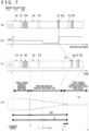
- the display controlling unit is configured to display a first section from the current point to a first point on a first time axis, to display a second section from the first point to a second point in a time axis that sequentially changes from the first time axis to a second time axis reduced at a predetermined ratio with respect to the first time axis, and to display a third section from the second point to a third point on the second time axis.
- Representing sections of a traveling route on a reach prediction time axis involves dividing a physical distance on the traveling route by an average speed for each section, and wherein the display controlling unit is configured to present information to the driver and to display all displayed sections of the traveling route as divided into three sections with changed time axis. This makes it possible for the driver to particularly know section information nearest in time in a limited display space and know section information farther in time.
- the information acquisition unit acquires traveling route information and traffic information relating to the traveling route. Further, according to active decision state of a return delay characteristic of a particular driver in a particular vehicle taking the traveling property of the own vehicle at the time, in the weather, and the like, into consideration, the display controlling unit displays a driver intervention requiring section and an automatic driving available section of the traveling route on a reach prediction time axis from the current point on the display device on the basis of the traveling route information and the traffic information.
- the display device may be a display device provided in a portable terminal, and the information processing apparatus may further include a communication unit configured to communicate with the portable terminal.
- the technology for performing specification notification like that of PTL 1 or PTL 2 since the technology does not perform optimization notification of return to manual driving from automatic driving taking a return delay characteristic into account in response to an environmental condition change, supposed by popularization of automatic driving, of a traveling route that changes every moment, a loading weight and a braking capacity of an own vehicle, further, a return characteristic of a driver, and still further, a state of the driver, the notification performed every time is performed at a timing different from a timing at which it is required by actual driving, and therefore, the necessity for actual return responsive to the notification gradually becomes ambiguous.
- the operational failure of the infrastructure described here refers to all that, in a case where a vehicle in which takeover from automatic driving to manual driving is not performed normally appears frequently, in a road section in which the vehicle traffic bandwidth of the road infrastructure is narrow, if many emergently slowdown vehicles or stopping vehicles appear, the flow of vehicles in the applicable road section is slowed down or disturbed, resulting in failure to maintain a normal traffic amount.
- the driver intervention requiring section may include a manual driving section, a takeover section from automatic driving to manual driving, and a cautious traveling section from the automatic driving.
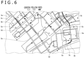
- the display controlling unit may display the automatic driving available section in a first color, display the manual driving section in a second color, and display the takeover section and the cautious traveling section in a third color. This makes it possible for the driver to visually observe a manual driving section, a takeover section from automatic driving to manual driving, a cautious traveling section from the automatic driving and an automatic driving available section on a traveling route.
- the reach prediction time from each current point to each takeover point is always updated and displayed intuitively as a time axis
- the return point is always known suitably in advance, and recognition of a takeover point can be performed easily and timely.
- the display controlling unit may display the first section with a first width, display the second section with a width that sequentially changes from the first width to a second width smaller than the first width, and display the third section with the second width.
- the driving vehicle intervention requiring section in the third section may be displayed with a fixed time length even if the driving vehicle intervention requiring section actually is equal to or smaller than the fixed time length. This makes it possible to display, in the third section in which the time axis is reduced by a great amount, the driving vehicle intervention requiring section of a short period so as to be easily recognizable by the driver.
- the display controlling unit may further display information relating to a point designated in each of the displayed sections. This makes it possible for the driver to designate an arbitrary point in each section and acquire information relating to the point.
- the display controlling unit may display the driving vehicle intervention requiring section that appears newly so as to be identifiable from the existing driving vehicle intervention requiring section.
- the newly appearing driving vehicle intervention requiring section is flickering displayed or displayed in a different color. This makes it possible for the driver to easily recognize the newly appearing driving vehicle intervention requiring section and explicitly grasp a plan to be coped with or changed in regard to traveling planning having been planned before the appearance of the additional event.
- the display controlling unit may put into an emphatically displayed state.
- flickering display display in a different color, illusion display by which the moving speed looks higher than an actual speed or, for example, wave display is used. This makes it possible for the driver to easily recognize that a driver intervention requiring section comes in a range of a fixed period of time from the current point.
- the flickering display of the dynamic display acts to stimulate the human dynamic visual acuity and is a method that uses means useful for calling for attention.
- the sensors 7920, 7922, 7924, 7926, 2928, and 7930 provided on the front, rear, sides, and corners of the vehicle 7900 and at the upper portion of the windshield in the interior of the vehicle may be, for example, ultrasonic sensors or radars.
- the sensors 7920, 7926, and 7930 provided on the front nose, rear bumper and backdoor and at the upper portion of the windshield in the interior of the vehicle may each be, for example, a LiDAR.
- the sensors 7920 to 7930 are used for detection principally of a preceding vehicle, a pedestrian, an obstacle, or the like. A result of such detection may be applied further to improvement in three-dimensional object display of the bird's eye display or omnidirectional stereoscopic display.
- the data acquisition unit 102 includes various sensors for detecting the current position of the own vehicle.
- the data acquisition unit 102 includes, for example, a GNSS receiver for receiving GNSS signals from GNSS (Global Navigation Satellite System) satellites, and so forth.
- GNSS Global Navigation Satellite System
- the data acquisition unit 102 includes various sensors, for example, for detecting information regarding the inside of the vehicle.
- the data acquisition unit 102 includes an imaging apparatus for imaging the driver, a biological sensor for detecting biological information of the driver, a microphone for collecting sound in the interior of the vehicle and so forth.
- the biological sensor is provided, for example, on a seat face, the steering wheel, or the like and detects a sitting state of a passenger sitting on a seat or biological information of the driver who grabs the steering wheel.
- a biological signal diversified observable data of a heart rate, a pulse rate, a blood flow, breathing, a mind-body correlation, a visual stimulus, brain waves, sweating, a drift, a head posture behavior, the eyes, gaze, a blink, a saccade, a micro saccade, fixation, staring, an iris pupil reaction, and so forth can be utilized.
- the communication unit 103 performs communication with the in-vehicle apparatus 104 as well as various apparatuses, servers, base stations, and so forth outside the vehicle to transmit data supplied from the components of the vehicle controlling system 100 and supplies received data to the components of the vehicle controlling system 100. It is to be noted that the communication protocol supported by the communication unit 103 is not specifically restricted, and also it is possible for the communication unit 103 to support a plurality of kinds of communication protocols.
- the communication unit 103 performs wireless communication with the in-vehicle apparatus 104 through a wireless LAN, Bluetooth (registered trademark), NFC (Near Field Communication), WUSB (Wireless USB), or the like. Further, the communication unit 103 performs wired communication with the in-vehicle apparatus 104 through a connection terminal not depicted (and a cable if necessary) by an USB (Universal Serial Bus), an HDMI (High-Definition Multimedia Interface), an MHL (Mobile High-definition Link), or the like.
- USB Universal Serial Bus
- HDMI High-Definition Multimedia Interface
- MHL Mobile High-definition Link
- the communication unit 103 performs communication, for example, with an apparatus (for example, an application server or a control server) existing in an external network (for example, the Internet, a cloud network or a network unique to a provider) through a base station or an access point. Further, the communication unit 103 performs communication with a terminal existing in the neighborhood of the own vehicle (for example, a terminal of a pedestrian or a shop or an MTC (Machine Type Communication) terminal), for example, using the P2P (Peer To Peer) technology.
- an apparatus for example, an application server or a control server
- an external network for example, the Internet, a cloud network or a network unique to a provider
- the communication unit 103 performs communication with a terminal existing in the neighborhood of the own vehicle (for example, a terminal of a pedestrian or a shop or an MTC (Machine Type Communication) terminal), for example, using the P2P (Peer To Peer) technology.
- P2P Peer To Peer
- the communication unit 103 performs V2X communication such as, for example, vehicle to vehicle (Vehicle to Vehicle) communication, road to vehicle (Vehicle to Infrastructure) communication, communication between the own vehicle and a home (Vehicle to Home), and pedestrian to vehicle (Vehicle to Pedestrian) communication.
- V2X communication such as, for example, vehicle to vehicle (Vehicle to Vehicle) communication, road to vehicle (Vehicle to Infrastructure) communication, communication between the own vehicle and a home (Vehicle to Home), and pedestrian to vehicle (Vehicle to Pedestrian) communication.
- the communication unit 103 includes a beacon reception unit, for example, and receives a radio wave or an electromagnetic wave originated from a wireless station or the like installed on a road to acquire information regarding the current position, traffic jams, traffic rules, required time, or the like.
- the in-vehicle apparatus 104 includes, for example, mobile equipment (a tablet, a smartphone, or the like) or a wearable device owned by a passenger, information equipment carried in or attached to the own vehicle, a navigation apparatus for performing a route search to an arbitrary destination, and so forth. It is to be noted that, if it is taken into consideration that, as a result of spread of automatic driving, an occupant is not necessarily fixed to a sitting fixed position, the in-vehicle apparatus 104 may be extensionally utilized to a video reproduction device, a game device, or an apparatus that can be removed from an installation position of the same.
- the body controlling unit 109 generates various control signals and supplies them to the body system 110 to perform control of the body system 110. Further, the body controlling unit 109 supplies control signals to the components other than the body system 110 to perform notification of a control state of the body system 110, and so forth as occasion demands.
- the body system 110 includes various apparatuses of the body system equipped on the vehicle body.
- the body system 110 includes a keyless entry system, a smart key system, a power window apparatus, power seats, a steering wheel, an air conditioning apparatus, various lamps (for example, a headlamp, a back lamp, a brake lamp, a turn signal, a fog lamp, and so forth), and so forth.
- the storage unit 111 includes magnetic storage devices such as, for example, a ROM (Read Only Memory), a RAM (Random Access Memory), and an HDD (Hard Disc Drive), a semiconductor storage device, an optical storage device, a magneto-optical storage device, and so forth.
- the storage unit 111 stores various programs, data, and so forth to be used by the components of the vehicle controlling system 100.
- the storage unit 111 stores map data of a three-dimensional high precision map such as a dynamic map, a global map that is lower in accuracy than the high precision map but covers a wider area, a local map including information around the own vehicle and so forth.
- the automatic driving controlling unit 112 performs control relating to automatic driving such as autonomous traveling, driving assistance and so forth.
- the automatic driving controlling unit 112 performs cooperative control for an aim of implementation of the ADAS (Advanced Driver Assistance System) functions including collision avoidance or impact mitigation of the own vehicle, follow traveling based on the inter-vehicle distance, vehicle speed maintaining traveling, collision warning of the own vehicle, lane departure traveling, and so forth.
- the automatic driving controlling unit 112 performs cooperative control for an aim of automatic traveling of autonomously driving without depending on operation of the driver, and so forth.
- the automatic driving controlling unit 112 includes a detection unit 131, a self-position estimation unit 132, a situation analysis unit 133, a planning unit 134, and a motion controlling unit 135.
- the detection unit 131 performs detection of various types of information necessary for control of automatic driving.
- the detection unit 131 includes an outside-vehicle information detection unit 141, an in-vehicle information detection unit 142, and a vehicle state detection unit 143.
- the in-vehicle information detection unit 142 has mainly two major roles, the first one of which is passive monitoring of the state of the driver during automatic driving and the second one of which is, after a request for return is issued from the system, to detect whether the ability of the driver such as peripheral recognition, perception, and determination as well as an operational capability of the steering equipment reaches a level at which manual driving is possible until a section for driving with caution is reached.
- failure self-diagnosis of the entire vehicle may be further performed such that, also in a case where degradation of the automatic driving function occurs due to some functional failure for automatic driving, early return to manual driving by the driver is encouraged similarly.
- the environment in the inside of the vehicle that is a detection target includes, for example, the temperature, humidity, brightness, smell, and so forth.
- the in-vehicle information detection unit 142 supplies data indicative of a result of the detection process to the situation recognition unit 153 of the situation analysis unit 133 and to the motion controlling unit 135.
- the in-vehicle information detection unit 142 issues an instruction to the emergency avoidance unit 171 or the like of the system to start a deceleration, escape and stopping procedure in order to escape the vehicle.
- the vehicle state detection unit 143 performs a detection process of a state of the own vehicle on the basis of data or signals from the components of the vehicle controlling system 100.
- the states of the own vehicle that become a detection target include, for example, a speed, an acceleration, a steering angle, presence or absence and the details of abnormality, a state of a driving operation, a position and an inclination of the power seat, a locked state of a door, states of other in-vehicle apparatuses, and so forth.
- the vehicle state detection unit 143 supplies data indicative of a result of the detection process to the situation recognition unit 153 of the situation analysis unit 133, emergency avoidance unit 171 of the motion controlling unit 135, and so forth.
- the self-position estimation unit 132 performs an estimation process of the position, posture, and so forth of the own vehicle on the basis of data or signals from the components of the vehicle controlling system 100, such as the outside-vehicle information detection unit 141, and the situation recognition unit 153 of the situation analysis unit 133. Further, the self-position estimation unit 132 generates a local map for use for estimation of the position of the own vehicle (hereinafter referred to as an own position estimation map) if necessary.
- the own position estimation map is a high accuracy map using, for example, a technology of SLAM (Simulated Localization and Mapping).
- the self-position estimation unit 132 supplies data indicative of a result of the estimation process to the map analysis unit 151, the traffic rule recognition unit 152, the situation recognition unit 153, and so forth of the situation analysis unit 133. Further, the self-position estimation unit 132 stores the own position estimation map into the storage unit 111.
- the situation analysis unit 133 performs an analysis process of the own vehicle and a surrounding situation.
- the situation analysis unit 133 includes the map analysis unit 151, the traffic rule recognition unit 152, the situation recognition unit 153, a situation prediction unit 154 and a learning unit 155.
- the map analysis unit 151 performs an analysis process of various maps stored in the storage unit 111 while using data or signals from the components of the vehicle controlling system 100, such as the self-position estimation unit 132 and the outside-vehicle information detection unit 141 as occasion demands to construct a map including information necessary for processing of automatic driving.
- the map analysis unit 151 supplies the constructed map to the traffic rule recognition unit 152, the situation recognition unit 153, the situation prediction unit 154 and a route planning unit 161, an action planning unit 162 and a motion planning unit 163 of the planning unit 134.
- the traffic rule recognition unit 152 performs a recognition process of traffic rules around the own vehicle on the basis of data or signals from the components of the vehicle controlling system 100, such as the self-position estimation unit 132, the outside-vehicle information detection unit 141, and the map analysis unit 151. By this recognition process, for example, the position and the state of a traffic light around the own vehicle, the details of a traffic regulation around the own vehicle, available lanes, and so forth are recognized.
- the traffic rule recognition unit 152 supplies data indicative of a result of the recognition process to the situation prediction unit 154 and so forth.
- the situation recognition unit 153 performs a recognition process of a situation relating to the own vehicle on the basis of data or signals from the components of the vehicle controlling system 100, such as the self-position estimation unit 132, the outside-vehicle information detection unit 141, the in-vehicle information detection unit 142, and the vehicle state detection unit 143, and the map analysis unit 151.
- the situation recognition unit 153 performs a recognition process of the situation of the own vehicle, situation around the own vehicle, situation of the driver of the own vehicle, and so forth. Further, the situation recognition unit 153 generates a local map to be used for recognition of the situation around the own vehicle (hereinafter referred to as a map for situation recognition) if necessary.
- the map for situation recognition is set as, for example, an occupancy grid map (Occupancy Grid Map).
- the situations of the own vehicle that become a recognition target include, for example, conditions unique to the vehicle such as the position, posture and movement (for example, the speed, acceleration, moving direction and so forth) of the own vehicle, and the movement of the center of gravity of the vehicle body in association with a loaded cargo quantity that determines the motion characteristics of the own vehicle and loading of the cargo, a tire pressure, braking distance movement in association with brake braking pad wear situation, permissible maximum deceleration braking for prevention of movement of the cargo caused by braking due to loaded cargo, and a centrifugal relaxation limit speed arising from a liquid cargo at the time of traveling on a curve, and conditions unique to the loaded cargo, and since the timing required for control differs depending on the properties of the vehicle itself in a quite same road environment such as a coefficient of friction of a road surface, a road curve, or a gradient, and on a loaded article, and so forth, it is necessary to perform collection of such various conditions and learn them so as to be reflected upon an optimum timing at which the control is to
- the situations around the own vehicle that become a recognition target include, for example, the type and the position of a stationary object around the own vehicle, the type, position and movement (for example, the speed, acceleration, moving direction, and so forth) of a moving object therearound, the configuration of the road therearound and the state of the road surface as well as the weather, humidity, brightness, and so forth therearound.
- the states of the driver that become a recognition target include, for example, the physical condition, awakening level, concentration, fatigue, movement of the line of sight, driving operations, and so forth.
- the control start point at which coping is demanded differs significantly depending upon a loaded amount loaded in the unique state of the vehicle, a chassis fixed state of the loading portion, a biased state of the center of gravity, a maximum possible-deceleration acceleration value, a maximum load possible centrifugal force, and a return response delay mount in response to the state of the driver.
- the situation recognition unit 153 supplies data indicative of a result of the recognition process (including, as occasion demands, the map for situation recognition) to the self-position estimation unit 132, the situation prediction unit 154, and so forth. Further, the situation recognition unit 153 stores the map for situation recognition into the storage unit 111.
- the driver can easily grasp up to which point the driver may not be requested to intervene with the driving in a certain fixed section ahead together with traveling, and there is a merit that the driver can perform engagement in a secondary task systematically. Necessity/unnecessity of driving intervention becomes clear to the driver, and in a secondary task involved in communication with a third party or the like, a significant role of information presentation is played in release planning of the driver from the secondary task or the like.
- the second time axis at the second point (time t1) is reduced at a ratio of hs/h0 from the first time axis.
- the reduction ratio is 1/8.
- the display in the second display section described above is, in a case where the vehicle is traveling at a fixed vehicle speed, equivalent to display where a traveling straight extension display section on the map is inclined obliquely to the moving direction or to a state in which the front of the road plane is viewed obliquely.
- the visual effect of this display section is that the perspective can be understood intuitively from the display picture height position, even if graduations or the like for accurate position display are not displayed on the screen, the sensory distance can be grasped easily.
- a remote section is reduced, since this is not a point at which the vehicle arrives quickly by traveling, although rough prediction is important, the driver need not intuitively grasp such accurate reach time information as that at a near point. Therefore, this is preferable also when the driver schedules secondary task execution.
- the third section from the second point (time t1) to the third point (time t3) is displayed on the second time axis (reduction ratio hs/h0) as a time linear display remote section.
- the driver can know details of section information nearest in time with a limited display space and can know section information more remote in time. It is to be noted that, when a remote portion is displayed with the display form for the second section maintained, this becomes lower than the human visual resolution and further becomes lower than the display resolution limit of the system. Therefore, it becomes impossible to discriminate information necessary for plan determination of a secondary task, and the significance of the display function is lost.
- the vehicle controlling system 100 has default values for time t0, t1 and t3. Since also it is considerable that the values of time t0, t1 and t2 are made different between long distance driving and short distance driving, the default values are not limited to one set, and a plurality of sets may be provided such that the driver (user) or the system selectively uses them in response to a traveling route. Also, it is considerable to allow the driver (user) to arbitrarily set the values of time t0, t1 and t3.
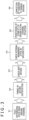
- FIGS. 8(a) and 8(b) each depict an example of a traveling section display image that is displayed finally. It is to be noted that, by the length of an arrow mark, whether the time axis is linear and further, a change of the reduction ratio of the time axis are depicted. In the case of FIG. 8(a) , all of the sections of the first, second and third sections are displayed with a first width maintained.
- the first section from the current point to the first point (time t0) is displayed with a first width
- the second section from the first point (time t0) to the second point (time t1) is displayed with a width sequentially changing from the first value to a second value that indicates a width narrower than the first width
- the third section from the second point (time T1) to the third point (time T2) is displayed with the second width.
- FIG. 7 is a display image in which only the reduction ratio in the moving direction is taken into consideration, by further changing the transverse width with respect to the moving direction of the display information artificially in accordance with the perspective, a perspective effect same as that obtained when the driver views toward the infinite direction along the progress of a road or the map is obtained, and intuitive grasping of a distribution of driving intervention requiring sections is facilitated in comparison with that when the screen is viewed at a moment.
- the second section is comparable with the road width of the road ahead and the arriving time at each applicable point in a case where the vehicle travels at a fixed speed, even if an accurate position graduation is not determined by observation, the reaching feeling to each point can be grasped intuitively, and the display form is considered to allow for time distribution.
- the display of the second manual driving section Sb in the third section indicates such a state that it is displayed in such a continuous manner as just described.
- the manual driving section Sb displayed in this manner actually includes, as depicted in FIG. 8(c) , a cautious traveling section Sd and an automatic driving available section Sa of a short period in addition to the manual driving section Sb. It is to be noted that, as hereinafter described, detailed display can be performed if, in a state in which traveling section display is given on a tablet or the like, the point is, for example, double-touched.
- FIGS. 9(a) to 9(d) each depict an example of change of traveling section display together with passage of time. Although this example depicts an example in which the second section is displayed in a tapering fashion, a case in which all sections are displayed with an equal width is also similar.
- FIGS. 10(a) and 10(b) each depict an example of a traveling section display image 200 on a traveling route displayed on the screen of a tablet 300.
- FIG. 10(a) depicts an example in a case where the tablet 300 is used vertically. In this case, the vehicle controlling system 100 is displayed in a bent state along the left side and the upper side and is displayed in parallel to a work window that is an execution screen for a secondary task performed on the tablet 300.
- FIG. 10(b) depicts an example in a case where the tablet 300 is used in landscape. Also in this case, the traveling section display image 200 is displayed in a bent state along the left side and the upper side and is displayed in parallel to a work window that is an execution screen for a secondary task performed on the tablet 300.
- FIG. 11 depicts an example of a state in which the driver executes a secondary task actually using the tablet 300.
- the tablet 300 is used in landscape.
- a traveling section display image 200 is displayed in a state in which it is bent along the left side and the upper side. It is to be noted that whether or not the traveling section display image 200 is to be displayed on the screen may be selectively performed by an operation of the driver (user). In this case, for example, in a case where the traveling section display image 200 is displayed on the screen, in a case where a driver intervention requiring section comes in a fixed period of time and this is to be notified to the driver, then the traveling section display image 200 may be displayed on the screen automatically.
- a task that provides a similar immersive sense includes watching of sports on live television or the like. Further, it is assumed that, during a period that involves lively discussion in a telephone conference or the like, depending upon a participation situation in the discussion, the driver becomes insensitive similarly to a return notification or an alert by the system not in the conference.
- a work for a slip inputting system to a tablet terminal apparatus can be classified to a secondary task of the type in which it is generally favorable that, from a point of view of the work efficiency, a series of inputting is performed continuously without interrupting the work and the inputting work is performed until the work settles down.
- the hesitation to interrupt can be reduced depending upon how the driver can comfortably watch the contents of the secondary task continued from the interruption point when the secondary task is interrupted and reproduction is restarted from the interruption point later.
- Such interruption of a secondary task for performing driving steering attention and actual steering return with the secondary task interrupted may be performed by an interruption procedure by the driver. Then, at this time, restart from the interruption point may be performed or the reproduction point may be reserved retroactively in advance so as to perform interruption.
- the interruption reproduction method is desirably inputted by such a method that, for example, an interruption menu is provided by single touch an appreciation monitoring screen and intuitive and rapid designation is possible such as interruption reproduction method designation or slider designation interruption of a retroactive point.
- retroactive reproduction from the interruption point may be performed.
- unlike continuous appreciation since appreciation has been once interrupted, even if the driver watches the contents from the interruption point upon restarting the reproduction of the contents, it is difficult to grasp the story of the contents.
- the effect of the present reproduction method can be recognized readily if it is taken as an example that, even if a person hears a witty comment in a comedy double act some times later after hearing a funny comment, this is not funny.
- index presentation traveling section display image 200
- a small icon for notification is displayed as a visual stimulus induction by flickering or the like in the work window 400 as depicted in FIG. 20(a) .
- the work screen is interrupted (partially obstructively) and a restart return point designation slider menu for an inputting work is displayed such that free setting can be performed by slider rotation of an optimum return point by the utilizer.
- the slider display may be a rotational display image of the rotation type in the counterclockwise direction as depicted in FIG. 20(b) , a horizontal linear display image as depicted in FIG. 21(a) or a vertical linear display image not depicted.
- the last input information point is the current point, and since a place not inputted as yet is not a point at which restart cannot be performed originally, it cannot be designated as a reproduction designation point upon restarting.
- the input point is progressed to a planned inputting place on an inputting application tool, and by executing screen simulation simple display upon return inputting, an optimum point determination for restarting the work retroactively can be performed.
- index presentation traveling section display image 200
- arrival at a takeover point in the moving direction is displayed in an enlarged scale like a traveling section display image 200' as depicted in FIG. 21(b) while the secondary task execution window 400 is reduced, and in some cases, the application inputting being executed as a secondary task may be force-quit.
- a slider menu (slider for return place designation with an input history on the screen upon restarting) 500 in which input work points (a CR (enter keyboard Carriage Return) execution point to an input work point and an input form completion point) are lined up explicitly in chronological order may be presented.
- input work points a CR (enter keyboard Carriage Return) execution point to an input work point and an input form completion point
- the slider may be closed by a process for slidably moving the slider with double fingers or by a close menu.
- a restart point may be designated by inputting a numerical value, hitting Carriage Return, moving the slider to a location at which work restarting is desired to be performed among a plurality of points and designating the applicable location by double touch or checkmark operation.
- an input work point of a terminal work and a reach point of a traveling environment on a tablet or the like can be grasped intuitively by the user, not only an execution task of a secondary task and display update information are temporarily displayed simply to the driver but also a synchronous record with the task may be further stored into a recording apparatus such that the task playback function and so forth can be used together by a scroll of a section approach window involved in the progress on the menu and a screen double touch or triple touch operation with a work recovery point and so forth.
- an interaction between preceding and succeeding pieces of input information is important, and for example, in a case where a plurality of pieces of related information are successively inputted into a table or the like, in a case where an item is selected and a series of information interlocked with the item are to be inputted, if inputting is interrupted at a place that is not good to stop under an incomplete condition, depending upon the memory of the driver upon restart the work, there is the possibility that time may be required to recall the interruption place or incorrect input may occur.
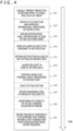
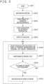
- the system detects notification acknowledgement response of the performer of the secondary task. For example, in a case where the secondary task utilizing an information terminal is performed and a small icon for notification is flickered or the like as a notification in the work window 400 as described above, for example, a touch operation or the like by the performer with the icon is detected. Further, at step S54, the system issues an interruption request of the inputting work of the secondary task to the performer of the secondary task and gives a notice for screen reduction and interruption.
- step S68 the system monitors and acquires LDM information, driver states and vehicle self-diagnosis information necessary for automatic driving restart availability decision. Then, at step S69, the system determines whether or not the vehicle has entered again into an executable section of the secondary task. If the vehicle has not entered again the executable section of the secondary task, the system continues the process at step S68. In contrast, if the vehicle has entered again the executable section of the secondary task, the system determines automatic driving available section entry at step S70.
- the timeout decision performed at step S74 may be a procedure that, in a case where the driver does not perform secondary task restart within a fixed period of time, interruption of the work equivalent to transition to a standby mode that is an energy saving mode of a terminal or the like, a pause mode in which interruption information for turning off the power supply fully is recorded to close the work or the like is performed such that loss of the work contents that have been done so far is avoided by manual driving return that requires long-term work interruption.
- step S73 When the selection of the return menu is performed at step S73, if the work restart point designation is performed through a slider menu or the like by the system at step S75, at step S76, the system performs work restart in accordance with the designation input. Thereafter, the system ends the series of processes at step S77. It is to be noted that, when it is a timeout at step S74, the system immediately advances to step S77 to end the series of processes.
- the timing at which return is demanded to the driver not necessarily is a timing that is good for interruption of the secondary task being executed.
- the timing at which return is demanded to the driver not necessarily is a timing that is good for interruption of the secondary task being executed.
- the timing at which return is demanded to the driver not necessarily is a timing that is good for interruption of the secondary task being executed.
- the timing at which return is demanded to the driver not necessarily is a timing that is good for interruption of the secondary task being executed.
- an explicit menu that facilitates work designation point return by the user on an execution application of a secondary task may further be provided auxiliarily.
- an inputting work point of a terminal work on a tablet or the like and a reaching point of a traveling environment can be grasped intuitively by the user, not only an execution task of the secondary task and display update information are temporarily presented to the driver simply such that a task playback function and so forth can be used by both of a scroll of a section approach window together with traveling on a menu and a screen double touch or triple touch operation of a work recovery point or the like but also synchronous recording with the task may be further stored into a recording apparatus.
- the steps described in the description of the flow charts given hereinabove not only can be executed by a single apparatus but also can be shared and executed by a plurality of apparatuses. Further, in a case where one step includes a plurality of processes, the plurality of processes included in the one step can be executed by a single apparatus and also can be executed by sharing by a plurality of apparatuses.
Landscapes
- Engineering & Computer Science (AREA)
- Radar, Positioning & Navigation (AREA)
- Remote Sensing (AREA)
- Automation & Control Theory (AREA)
- Transportation (AREA)
- Mechanical Engineering (AREA)
- Physics & Mathematics (AREA)
- General Physics & Mathematics (AREA)
- Chemical & Material Sciences (AREA)
- Combustion & Propulsion (AREA)
- Human Computer Interaction (AREA)
- Mathematical Physics (AREA)
- Life Sciences & Earth Sciences (AREA)
- Atmospheric Sciences (AREA)
- Biodiversity & Conservation Biology (AREA)
- Ecology (AREA)
- Environmental & Geological Engineering (AREA)
- Environmental Sciences (AREA)
- Traffic Control Systems (AREA)
- Control Of Driving Devices And Active Controlling Of Vehicle (AREA)
- Navigation (AREA)
Claims (11)
- Informationsverarbeitungseinrichtung, umfassend:eine Informationserfassungseinheit (102), die konfiguriert ist, um Reiserouteninformationen bezüglich einer Reiseroute eines eigenen Fahrzeugs und Verkehrsinformationen bezüglich der Reiseroute zu erfassen; undeine Anzeigesteuereinheit (105), die konfiguriert ist, um einen Reiseroutenabschnitt, der ein Eingreifen des Fahrers erfordert (Sb, Sc, Sd), und einen Abschnitt, in dem automatisches Fahren verfügbar ist (Sa), auf einer Zeitachse für die Reichweitenvorhersage von einem aktuellen Punkt anzuzeigen, wobei der aktuelle Punkt ein Punkt ist, zu dem das eigene Fahrzeug aktuell fährt, auf einer Anzeigevorrichtung auf der Grundlage der Reiserouteninformationen und der Verkehrsinformationen, wobei das Darstellen der Abschnitte einer Reiseroute auf einer Zeitachse für die Reichweitenvorhersage das Teilen einer physischen Entfernung auf der Reiseroute durch eine Durchschnittsgeschwindigkeit für jeden Abschnitt beinhaltet, und wobei die Anzeigesteuereinheit konfiguriert ist, um dem Fahrer Informationen zu präsentieren und alle angezeigten Abschnitte der Reiseroute als in drei Abschnitte mit geänderter Zeitachse unterteilt anzuzeigen, undwobeidie Anzeigesteuereinheit konfiguriert ist,um einen ersten Abschnitt vom aktuellen Punkt bis zu einem ersten Punkt auf einer ersten Zeitachse anzuzeigen,einen zweiten Abschnitt von dem ersten Punkt zu einem zweiten Punkt in einer Zeitachse anzuzeigen, die sequenziell von der ersten Zeitachse zu einer zweiten Zeitachse wechselt, die in einem vorbestimmten Verhältnis in Bezug auf die erste Zeitachse verkleinert ist, undum einen dritten Abschnitt vom zweiten Punkt bis zu einem dritten Punkt auf der zweiten Zeitachse anzuzeigen.
- Informationsverarbeitungseinrichtung nach Anspruch 1, wobei
der Abschnitt, der ein Eingreifen des Fahrers erfordert, einen Abschnitt zum manuellen Fahren (Sb), einen Übernahmeabschnitt vom automatischen Fahren zum manuellen Fahren (Sc) und einen Abschnitt zum vorsichtigen Fahren (Sd) vom automatischen Fahren umfasst. - Informationsverarbeitungseinrichtung nach Anspruch 2, wobei
die Anzeigesteuereinheit konfiguriert ist, um den Abschnitt, in dem automatisches Fahren verfügbar ist (Sa), in einer ersten Farbe anzuzeigen, den Abschnitt mit manuellem Fahren (Sb) in einer zweiten Farbe anzuzeigen und den Übernahmeabschnitt (Sc) und den Abschnitt zum vorsichtigen Fahren (Sd) in einer dritten Farbe anzuzeigen. - Informationsverarbeitungseinrichtung nach einem der vorstehenden Ansprüche, wobeidie Anzeigesteuereinheit konfiguriert ist,um den ersten Abschnitt mit einer ersten Breite anzuzeigen,den zweiten Abschnitt mit einer Breite anzuzeigen, die sich sequenziell von der ersten Breite zu einer zweiten Breite ändert, die kleiner als die erste Breite ist, undum den dritten Abschnitt mit der zweiten Breite anzuzeigen.
- Informationsverarbeitungseinrichtung nach einem der vorstehenden Ansprüche, wobei
die Anzeigesteuereinheit konfiguriert ist, um den Abschnitt, der ein Eingreifen in das fahrende Fahrzeug erfordert, im dritten Abschnitt mit einer festen Zeitdauer anzuzeigen, selbst wenn der Abschnitt, der ein Eingreifen in das fahrende Fahrzeug erfordert, tatsächlich gleich oder kürzer als die feste Zeitdauer ist. - Informationsverarbeitungseinrichtung nach Anspruch 1, wobei
die Anzeigesteuereinheit ferner konfiguriert ist, um Informationen anzuzeigen, die sich auf einen in jedem der angezeigten Abschnitte bezeichneten Punkt beziehen. - Informationsverarbeitungseinrichtung nach Anspruch 1, wobei
die Anzeigesteuereinheit konfiguriert ist, um den neu erscheinenden Abschnitt, der ein Eingreifen in das fahrende Fahrzeug erfordert, so anzuzeigen, dass er von dem bestehenden Abschnitt, der ein Eingreifen in das fahrende Fahrzeug erfordert, unterscheidbar ist. - Informationsverarbeitungseinrichtung nach Anspruch 1, wobei
wenn der Abschnitt, der ein Eingreifen des Fahrers erfordert, in einem Bereich von einem festen Zeitraum ab dem aktuellen Punkt liegt, die Anzeigesteuereinheit konfiguriert ist, um den Abschnitt, der ein Eingreifen des Fahrers erfordert, in einen hervorgehobenen Anzeigezustand zu versetzen. - Informationsverarbeitungseinrichtung nach Anspruch 1, wobei
die Anzeigesteuereinheit konfiguriert ist, um Anzeigebilder in den Abschnitten und einem Arbeitsfenster anzuzeigen. - Informationsverarbeitungseinrichtung nach Anspruch 1,wobei die Anzeigevorrichtung eine in einem tragbaren Endgerät bereitgestellte Anzeigevorrichtung ist, unddie Informationsverarbeitungseinrichtung ferner umfasst:
eine Kommunikationseinheit (103), die zur Kommunikation mit dem tragbaren Endgerät konfiguriert ist. - Informationsverarbeitungsverfahren, umfassend:durch eine Informationserfassungseinheit (102), einen Schritt zum Erfassen von Reiserouteninformationen, die sich auf eine Reiseroute eines eigenen Fahrzeugs beziehen, und von Verkehrsinformationen bezüglich der Reiseroute; unddurch eine Anzeigesteuereinheit, einen Schritt des Anzeigens eines Abschnitts (Sb, Sc, Sd) der Reiseroute, der ein Eingreifen des Fahrers erfordert, und eines Abschnitts (Sa) der Reiseroute, der für automatisches Fahren verfügbar ist, auf einer Zeitachse der Reichweitenvorhersage von einem aktuellen Punkt aus, wobei der aktuelle Punkt ein Punkt ist, an dem das eigene Fahrzeug aktuell fährt, auf einer Anzeigevorrichtung auf der Grundlage der Reiserouteninformationen und der Verkehrsinformationen, wobei das Darstellen von Abschnitten einer Reiseroute auf einer Zeitachse für die Reichweitenvorhersage das Teilen einer physischen Entfernung auf der Reiseroute durch eine Durchschnittsgeschwindigkeit für jeden Abschnitt beinhaltet, und des Präsentierens der Informationen für den Fahrer durch Anzeigen aller angezeigten Abschnitte der Reiseroute, aufgeteilt in drei Abschnitte mit geänderter Zeitachse, durch Ausführen der SchritteAnzeigen eines ersten Abschnitts vom aktuellen Punkt bis zu einem ersten Punkt auf einer ersten Zeitachse,Anzeigen eines zweiten Abschnitts von dem ersten Punkt zu einem zweiten Punkt in einer Zeitachse, die sequenziell von der ersten Zeitachse zu einer zweiten Zeitachse wechselt, die in einem vorbestimmten Verhältnis in Bezug auf die erste Zeitachse verkleinert ist, undAnzeigen eines dritten Abschnitts vom zweiten Punkt zu einem dritten Punkt auf der zweiten Zeitachse.
Priority Applications (1)
| Application Number | Priority Date | Filing Date | Title |
|---|---|---|---|
| EP25165251.7A EP4550294A3 (de) | 2017-10-24 | 2018-10-17 | Informationsverarbeitungsvorrichtung und informationsverarbeitungsvorrichtung |
Applications Claiming Priority (2)
| Application Number | Priority Date | Filing Date | Title |
|---|---|---|---|
| JP2017205671 | 2017-10-24 | ||
| PCT/JP2018/038740 WO2019082774A1 (ja) | 2017-10-24 | 2018-10-17 | 情報処理装置および情報処理方法 |
Related Child Applications (1)
| Application Number | Title | Priority Date | Filing Date |
|---|---|---|---|
| EP25165251.7A Division EP4550294A3 (de) | 2017-10-24 | 2018-10-17 | Informationsverarbeitungsvorrichtung und informationsverarbeitungsvorrichtung |
Publications (3)
| Publication Number | Publication Date |
|---|---|
| EP3702732A1 EP3702732A1 (de) | 2020-09-02 |
| EP3702732A4 EP3702732A4 (de) | 2020-12-30 |
| EP3702732B1 true EP3702732B1 (de) | 2025-04-09 |
Family
ID=66246504
Family Applications (2)
| Application Number | Title | Priority Date | Filing Date |
|---|---|---|---|
| EP25165251.7A Pending EP4550294A3 (de) | 2017-10-24 | 2018-10-17 | Informationsverarbeitungsvorrichtung und informationsverarbeitungsvorrichtung |
| EP18869499.6A Active EP3702732B1 (de) | 2017-10-24 | 2018-10-17 | Informationsverarbeitungsvorrichtung und informationsverarbeitungsverfahren |
Family Applications Before (1)
| Application Number | Title | Priority Date | Filing Date |
|---|---|---|---|
| EP25165251.7A Pending EP4550294A3 (de) | 2017-10-24 | 2018-10-17 | Informationsverarbeitungsvorrichtung und informationsverarbeitungsvorrichtung |
Country Status (6)
| Country | Link |
|---|---|
| US (2) | US11524698B2 (de) |
| EP (2) | EP4550294A3 (de) |
| JP (1) | JP7203035B2 (de) |
| KR (1) | KR102599937B1 (de) |
| CN (1) | CN111247394B (de) |
| WO (1) | WO2019082774A1 (de) |
Families Citing this family (24)
| Publication number | Priority date | Publication date | Assignee | Title |
|---|---|---|---|---|
| EP4550294A3 (de) | 2017-10-24 | 2025-06-18 | Sony Semiconductor Solutions Corporation | Informationsverarbeitungsvorrichtung und informationsverarbeitungsvorrichtung |
| FR3084628B1 (fr) * | 2018-07-31 | 2021-06-11 | Renault Sas | Procede de determination d'un type d'emplacement de stationnement |
| JP7207101B2 (ja) * | 2019-03-29 | 2023-01-18 | いすゞ自動車株式会社 | 輸送管理装置、輸送管理方法、および、輸送システム |
| JP2020187563A (ja) | 2019-05-15 | 2020-11-19 | 本田技研工業株式会社 | 情報処理装置、車両制御装置、情報処理方法、及びプログラム |
| JP7107281B2 (ja) * | 2019-06-07 | 2022-07-27 | 株式会社デンソー | 情報提示制御装置 |
| JP2021043571A (ja) * | 2019-09-09 | 2021-03-18 | ソニーセミコンダクタソリューションズ株式会社 | 情報処理装置、移動装置、情報処理システム、および方法、並びにプログラム |
| CN114430898B (zh) * | 2019-09-19 | 2024-08-06 | 日产自动车株式会社 | 显示器的显示控制方法和装置 |
| JP7159137B2 (ja) | 2019-09-25 | 2022-10-24 | 本田技研工業株式会社 | 車両制御装置、車両制御方法、およびプログラム |
| KR20220113947A (ko) | 2019-12-26 | 2022-08-17 | 소니 세미컨덕터 솔루션즈 가부시키가이샤 | 정보 처리 장치, 이동 장치, 정보 처리 시스템 및 방법, 그리고 프로그램 |
| WO2021145131A1 (ja) | 2020-01-17 | 2021-07-22 | ソニーセミコンダクタソリューションズ株式会社 | 情報処理装置、情報処理システム、情報処理方法及び情報処理プログラム |
| KR102517818B1 (ko) * | 2020-05-11 | 2023-04-04 | 광주과학기술원 | 혼합현실 기반 체험 시뮬레이터 |
| JP7484689B2 (ja) * | 2020-05-22 | 2024-05-16 | 株式会社デンソー | 制御システム、制御装置および制御プログラム |
| EP4160569A4 (de) | 2020-06-01 | 2023-11-08 | Sony Group Corporation | Informationsverarbeitungsvorrichtung, informationsverarbeitungsverfahren und speichermedium |
| CN111882112B (zh) * | 2020-07-01 | 2024-05-10 | 北京嘀嘀无限科技发展有限公司 | 一种预测到达时间的方法和系统 |
| JP7479965B2 (ja) * | 2020-07-02 | 2024-05-09 | 日野自動車株式会社 | 車両制御装置及び車両制御方法 |
| JP7603396B2 (ja) * | 2020-08-31 | 2024-12-20 | 住友化学株式会社 | 二液型偏光膜形成用組成物 |
| CN112464749B (zh) * | 2020-11-11 | 2025-02-07 | 鹏城实验室 | 一种基于规则与学习的交通场景异常目标检测方法 |
| DE102020214999A1 (de) | 2020-11-27 | 2022-06-02 | Ford Global Technologies, Llc | Verfahren und System zum Trainieren einer manuellen Übernahme einer Fahrzeugsteuerung, Fahrzeug, Computerprogramm und computerlesbarer Datenträger |
| JP7517254B2 (ja) * | 2021-06-07 | 2024-07-17 | トヨタ自動車株式会社 | 遠隔運転車両、遠隔運転システム、蛇行運転抑制方法、及び蛇行運転抑制プログラム |
| US12172659B2 (en) * | 2021-07-23 | 2024-12-24 | GM Global Technology Operations LLC | Allocation of non-monitoring periods during automated control of a device |
| US11919534B2 (en) * | 2021-08-03 | 2024-03-05 | Denso Corporation | Driver state guide device and driver state guide method |
| CN114047868A (zh) * | 2021-09-24 | 2022-02-15 | 北京车和家信息技术有限公司 | 播放界面的生成方法、装置、电子设备和存储介质 |
| WO2024248067A1 (ja) * | 2023-05-30 | 2024-12-05 | 株式会社 商船三井 | 航海支援システム |
| CN119773501B (zh) * | 2025-01-22 | 2025-10-31 | 润芯微科技(江苏)有限公司 | 一种车辆中控座舱智能显示系统 |
Family Cites Families (24)
| Publication number | Priority date | Publication date | Assignee | Title |
|---|---|---|---|---|
| JP4255007B2 (ja) | 2003-04-11 | 2009-04-15 | 株式会社ザナヴィ・インフォマティクス | ナビゲーション装置、およびその旅行時間算出方法 |
| JP2011075436A (ja) * | 2009-09-30 | 2011-04-14 | Pioneer Electronic Corp | 情報表示装置及び情報表示用プログラム |
| US8566348B2 (en) * | 2010-05-24 | 2013-10-22 | Intersect Ptp, Inc. | Systems and methods for collaborative storytelling in a virtual space |
| JP2012035745A (ja) * | 2010-08-06 | 2012-02-23 | Toshiba Corp | 表示装置、画像データ生成装置及び画像データ生成プログラム |
| US8560520B2 (en) * | 2010-08-26 | 2013-10-15 | Microsoft Corporation | Information retrieval using time |
| DE102010063339A1 (de) * | 2010-12-17 | 2012-06-21 | Bayerische Motoren Werke Aktiengesellschaft | Verarbeitung von Ereignissen in einem Fahrzeug |
| US20140278087A1 (en) * | 2013-03-14 | 2014-09-18 | Ford Global Technologies, Llc | Method and Apparatus for Predicting Times of High Driver Demand |
| DE102013219887A1 (de) * | 2013-10-01 | 2015-04-02 | Volkswagen Aktiengesellschaft | Verfahren für ein Fahrerassistenzsystem eines Fahrzeugs |
| JP6287264B2 (ja) * | 2014-01-27 | 2018-03-07 | アイシン・エィ・ダブリュ株式会社 | 経路案内システム、経路案内方法及びコンピュータプログラム |
| JP6287728B2 (ja) | 2014-09-25 | 2018-03-07 | 株式会社デンソー | 車載システム、車両制御装置、および車両制御装置用のプログラム |
| JP2016090274A (ja) | 2014-10-30 | 2016-05-23 | トヨタ自動車株式会社 | 警報装置、警報システム及び携帯端末 |
| EP3230142B1 (de) * | 2014-12-12 | 2022-03-16 | Sony Group Corporation | Verfahren zum wechseln der betriebsmodi eines fahrzeugs |
| JP2016139204A (ja) | 2015-01-26 | 2016-08-04 | 株式会社デンソー | 危険度表示装置 |
| JP6288859B2 (ja) * | 2015-07-07 | 2018-03-07 | 本田技研工業株式会社 | 車両制御装置、車両制御方法、および車両制御プログラム |
| KR20170016262A (ko) * | 2015-08-03 | 2017-02-13 | 엘지전자 주식회사 | 이동 단말기 및 그것의 제어방법 |
| EP3353497B1 (de) * | 2015-09-24 | 2021-09-01 | Apple Inc. | System und verfahren zur erzeugung einer interaktiven benutzerschnittstelle |
| JP6641916B2 (ja) * | 2015-11-20 | 2020-02-05 | オムロン株式会社 | 自動運転支援装置、自動運転支援システム、自動運転支援方法および自動運転支援プログラム |
| US11087291B2 (en) * | 2015-11-24 | 2021-08-10 | Honda Motor Co., Ltd.. | Action planning and execution support device |
| JP6508072B2 (ja) * | 2016-01-26 | 2019-05-08 | 株式会社デンソー | 報知制御装置及び報知制御方法 |
| CA3014660C (en) * | 2016-02-15 | 2021-08-17 | Allstate Insurance Company | Early notification of non-autonomous area |
| CA3014656C (en) * | 2016-02-15 | 2021-10-26 | Allstate Insurance Company | Early notification of non-autonomous area |
| US20170315771A1 (en) * | 2016-04-28 | 2017-11-02 | Toyota Motor Engineering & Manufacturing North America, Inc. | System and method for selectively displaying images in an autonomous vehicle |
| US10746560B2 (en) * | 2017-09-05 | 2020-08-18 | Byton Limited | Interactive mapping |
| EP4550294A3 (de) | 2017-10-24 | 2025-06-18 | Sony Semiconductor Solutions Corporation | Informationsverarbeitungsvorrichtung und informationsverarbeitungsvorrichtung |
-
2018
- 2018-10-17 EP EP25165251.7A patent/EP4550294A3/de active Pending
- 2018-10-17 EP EP18869499.6A patent/EP3702732B1/de active Active
- 2018-10-17 WO PCT/JP2018/038740 patent/WO2019082774A1/ja not_active Ceased
- 2018-10-17 CN CN201880068449.8A patent/CN111247394B/zh active Active
- 2018-10-17 JP JP2019551059A patent/JP7203035B2/ja active Active
- 2018-10-17 KR KR1020207010645A patent/KR102599937B1/ko active Active
- 2018-10-17 US US16/757,366 patent/US11524698B2/en active Active
-
2022
- 2022-11-28 US US17/994,967 patent/US12122408B2/en active Active
Also Published As
| Publication number | Publication date |
|---|---|
| EP4550294A2 (de) | 2025-05-07 |
| US20230092167A1 (en) | 2023-03-23 |
| KR102599937B1 (ko) | 2023-11-09 |
| CN111247394A (zh) | 2020-06-05 |
| US11524698B2 (en) | 2022-12-13 |
| EP4550294A3 (de) | 2025-06-18 |
| WO2019082774A1 (ja) | 2019-05-02 |
| US12122408B2 (en) | 2024-10-22 |
| KR20200075831A (ko) | 2020-06-26 |
| JP7203035B2 (ja) | 2023-01-12 |
| CN111247394B (zh) | 2024-03-26 |
| EP3702732A4 (de) | 2020-12-30 |
| JPWO2019082774A1 (ja) | 2020-12-17 |
| US20210188301A1 (en) | 2021-06-24 |
| EP3702732A1 (de) | 2020-09-02 |
Similar Documents
| Publication | Publication Date | Title |
|---|---|---|
| US12122408B2 (en) | Information processing apparatus and information processing method | |
| EP3712028B1 (de) | Informationsverarbeitungsvorrichtung und informationsverarbeitungsverfahren | |
| US20240294194A1 (en) | Information processing apparatus, moving apparatus, and method, and program | |
| JP7431223B2 (ja) | 情報処理装置、移動装置、および方法、並びにプログラム | |
| US20210188289A1 (en) | Information processing device, moving apparatus, method, and program | |
| CN114930422B (zh) | 信息处理设备、移动装置、信息处理系统、信息处理方法和程序 | |
| CN114340970A (zh) | 信息处理设备、移动设备、信息处理系统、方法和程序 | |
| JP2022111156A (ja) | 車両制御装置および車両制御方法 |
Legal Events
| Date | Code | Title | Description |
|---|---|---|---|
| STAA | Information on the status of an ep patent application or granted ep patent |
Free format text: STATUS: THE INTERNATIONAL PUBLICATION HAS BEEN MADE |
|
| PUAI | Public reference made under article 153(3) epc to a published international application that has entered the european phase |
Free format text: ORIGINAL CODE: 0009012 |
|
| STAA | Information on the status of an ep patent application or granted ep patent |
Free format text: STATUS: REQUEST FOR EXAMINATION WAS MADE |
|
| 17P | Request for examination filed |
Effective date: 20200417 |
|
| AK | Designated contracting states |
Kind code of ref document: A1 Designated state(s): AL AT BE BG CH CY CZ DE DK EE ES FI FR GB GR HR HU IE IS IT LI LT LU LV MC MK MT NL NO PL PT RO RS SE SI SK SM TR |
|
| AX | Request for extension of the european patent |
Extension state: BA ME |
|
| A4 | Supplementary search report drawn up and despatched |
Effective date: 20201130 |
|
| RIC1 | Information provided on ipc code assigned before grant |
Ipc: B60W 40/04 20060101ALI20201124BHEP Ipc: G08G 1/16 20060101ALI20201124BHEP Ipc: G01C 21/26 20060101ALI20201124BHEP Ipc: G01C 21/36 20060101AFI20201124BHEP Ipc: B60W 50/14 20200101ALI20201124BHEP |
|
| DAV | Request for validation of the european patent (deleted) | ||
| DAX | Request for extension of the european patent (deleted) | ||
| RIN1 | Information on inventor provided before grant (corrected) |
Inventor name: OBA, EIJI |
|
| STAA | Information on the status of an ep patent application or granted ep patent |
Free format text: STATUS: EXAMINATION IS IN PROGRESS |
|
| 17Q | First examination report despatched |
Effective date: 20230214 |
|
| GRAP | Despatch of communication of intention to grant a patent |
Free format text: ORIGINAL CODE: EPIDOSNIGR1 |
|
| STAA | Information on the status of an ep patent application or granted ep patent |
Free format text: STATUS: GRANT OF PATENT IS INTENDED |
|
| INTG | Intention to grant announced |
Effective date: 20241029 |
|
| GRAS | Grant fee paid |
Free format text: ORIGINAL CODE: EPIDOSNIGR3 |
|
| GRAA | (expected) grant |
Free format text: ORIGINAL CODE: 0009210 |
|
| STAA | Information on the status of an ep patent application or granted ep patent |
Free format text: STATUS: THE PATENT HAS BEEN GRANTED |
|
| P01 | Opt-out of the competence of the unified patent court (upc) registered |
Free format text: CASE NUMBER: APP_6751/2025 Effective date: 20250210 |
|
| AK | Designated contracting states |
Kind code of ref document: B1 Designated state(s): AL AT BE BG CH CY CZ DE DK EE ES FI FR GB GR HR HU IE IS IT LI LT LU LV MC MK MT NL NO PL PT RO RS SE SI SK SM TR |
|
| REG | Reference to a national code |
Ref country code: GB Ref legal event code: FG4D |
|
| REG | Reference to a national code |
Ref country code: CH Ref legal event code: EP |
|
| REG | Reference to a national code |
Ref country code: DE Ref legal event code: R096 Ref document number: 602018081029 Country of ref document: DE |
|
| REG | Reference to a national code |
Ref country code: IE Ref legal event code: FG4D |
|
| REG | Reference to a national code |
Ref country code: NL Ref legal event code: FP |
|
| REG | Reference to a national code |
Ref country code: AT Ref legal event code: MK05 Ref document number: 1783871 Country of ref document: AT Kind code of ref document: T Effective date: 20250409 |
|
| PG25 | Lapsed in a contracting state [announced via postgrant information from national office to epo] |
Ref country code: PT Free format text: LAPSE BECAUSE OF FAILURE TO SUBMIT A TRANSLATION OF THE DESCRIPTION OR TO PAY THE FEE WITHIN THE PRESCRIBED TIME-LIMIT Effective date: 20250811 Ref country code: ES Free format text: LAPSE BECAUSE OF FAILURE TO SUBMIT A TRANSLATION OF THE DESCRIPTION OR TO PAY THE FEE WITHIN THE PRESCRIBED TIME-LIMIT Effective date: 20250409 Ref country code: FI Free format text: LAPSE BECAUSE OF FAILURE TO SUBMIT A TRANSLATION OF THE DESCRIPTION OR TO PAY THE FEE WITHIN THE PRESCRIBED TIME-LIMIT Effective date: 20250409 |
|
| REG | Reference to a national code |
Ref country code: LT Ref legal event code: MG9D |
|
| PG25 | Lapsed in a contracting state [announced via postgrant information from national office to epo] |
Ref country code: NO Free format text: LAPSE BECAUSE OF FAILURE TO SUBMIT A TRANSLATION OF THE DESCRIPTION OR TO PAY THE FEE WITHIN THE PRESCRIBED TIME-LIMIT Effective date: 20250709 Ref country code: GR Free format text: LAPSE BECAUSE OF FAILURE TO SUBMIT A TRANSLATION OF THE DESCRIPTION OR TO PAY THE FEE WITHIN THE PRESCRIBED TIME-LIMIT Effective date: 20250710 |
|
| PG25 | Lapsed in a contracting state [announced via postgrant information from national office to epo] |
Ref country code: PL Free format text: LAPSE BECAUSE OF FAILURE TO SUBMIT A TRANSLATION OF THE DESCRIPTION OR TO PAY THE FEE WITHIN THE PRESCRIBED TIME-LIMIT Effective date: 20250409 |
|
| PGFP | Annual fee paid to national office [announced via postgrant information from national office to epo] |
Ref country code: NL Payment date: 20250923 Year of fee payment: 8 |
|
| PG25 | Lapsed in a contracting state [announced via postgrant information from national office to epo] |
Ref country code: BG Free format text: LAPSE BECAUSE OF FAILURE TO SUBMIT A TRANSLATION OF THE DESCRIPTION OR TO PAY THE FEE WITHIN THE PRESCRIBED TIME-LIMIT Effective date: 20250409 |
|
| PG25 | Lapsed in a contracting state [announced via postgrant information from national office to epo] |
Ref country code: HR Free format text: LAPSE BECAUSE OF FAILURE TO SUBMIT A TRANSLATION OF THE DESCRIPTION OR TO PAY THE FEE WITHIN THE PRESCRIBED TIME-LIMIT Effective date: 20250409 |
|
| PG25 | Lapsed in a contracting state [announced via postgrant information from national office to epo] |
Ref country code: AT Free format text: LAPSE BECAUSE OF FAILURE TO SUBMIT A TRANSLATION OF THE DESCRIPTION OR TO PAY THE FEE WITHIN THE PRESCRIBED TIME-LIMIT Effective date: 20250409 |
|
| PGFP | Annual fee paid to national office [announced via postgrant information from national office to epo] |
Ref country code: FR Payment date: 20250924 Year of fee payment: 8 |
|
| PG25 | Lapsed in a contracting state [announced via postgrant information from national office to epo] |
Ref country code: RS Free format text: LAPSE BECAUSE OF FAILURE TO SUBMIT A TRANSLATION OF THE DESCRIPTION OR TO PAY THE FEE WITHIN THE PRESCRIBED TIME-LIMIT Effective date: 20250709 |
|
| PG25 | Lapsed in a contracting state [announced via postgrant information from national office to epo] |
Ref country code: IS Free format text: LAPSE BECAUSE OF FAILURE TO SUBMIT A TRANSLATION OF THE DESCRIPTION OR TO PAY THE FEE WITHIN THE PRESCRIBED TIME-LIMIT Effective date: 20250809 |
|
| PG25 | Lapsed in a contracting state [announced via postgrant information from national office to epo] |
Ref country code: LV Free format text: LAPSE BECAUSE OF FAILURE TO SUBMIT A TRANSLATION OF THE DESCRIPTION OR TO PAY THE FEE WITHIN THE PRESCRIBED TIME-LIMIT Effective date: 20250409 |
|
| PGFP | Annual fee paid to national office [announced via postgrant information from national office to epo] |
Ref country code: DE Payment date: 20250923 Year of fee payment: 8 |
|
| REG | Reference to a national code |
Ref country code: DE Ref legal event code: R097 Ref document number: 602018081029 Country of ref document: DE |
|
| PG25 | Lapsed in a contracting state [announced via postgrant information from national office to epo] |
Ref country code: SM Free format text: LAPSE BECAUSE OF FAILURE TO SUBMIT A TRANSLATION OF THE DESCRIPTION OR TO PAY THE FEE WITHIN THE PRESCRIBED TIME-LIMIT Effective date: 20250409 Ref country code: DK Free format text: LAPSE BECAUSE OF FAILURE TO SUBMIT A TRANSLATION OF THE DESCRIPTION OR TO PAY THE FEE WITHIN THE PRESCRIBED TIME-LIMIT Effective date: 20250409 |
|
| PG25 | Lapsed in a contracting state [announced via postgrant information from national office to epo] |
Ref country code: CZ Free format text: LAPSE BECAUSE OF FAILURE TO SUBMIT A TRANSLATION OF THE DESCRIPTION OR TO PAY THE FEE WITHIN THE PRESCRIBED TIME-LIMIT Effective date: 20250409 |
|
| PG25 | Lapsed in a contracting state [announced via postgrant information from national office to epo] |
Ref country code: EE Free format text: LAPSE BECAUSE OF FAILURE TO SUBMIT A TRANSLATION OF THE DESCRIPTION OR TO PAY THE FEE WITHIN THE PRESCRIBED TIME-LIMIT Effective date: 20250409 |
|
| PG25 | Lapsed in a contracting state [announced via postgrant information from national office to epo] |
Ref country code: SK Free format text: LAPSE BECAUSE OF FAILURE TO SUBMIT A TRANSLATION OF THE DESCRIPTION OR TO PAY THE FEE WITHIN THE PRESCRIBED TIME-LIMIT Effective date: 20250409 Ref country code: RO Free format text: LAPSE BECAUSE OF FAILURE TO SUBMIT A TRANSLATION OF THE DESCRIPTION OR TO PAY THE FEE WITHIN THE PRESCRIBED TIME-LIMIT Effective date: 20250409 |
|
| PG25 | Lapsed in a contracting state [announced via postgrant information from national office to epo] |
Ref country code: IT Free format text: LAPSE BECAUSE OF FAILURE TO SUBMIT A TRANSLATION OF THE DESCRIPTION OR TO PAY THE FEE WITHIN THE PRESCRIBED TIME-LIMIT Effective date: 20250409 |
|
| PLBE | No opposition filed within time limit |
Free format text: ORIGINAL CODE: 0009261 |
|
| STAA | Information on the status of an ep patent application or granted ep patent |
Free format text: STATUS: NO OPPOSITION FILED WITHIN TIME LIMIT |
|
| REG | Reference to a national code |
Ref country code: CH Ref legal event code: L10 Free format text: ST27 STATUS EVENT CODE: U-0-0-L10-L00 (AS PROVIDED BY THE NATIONAL OFFICE) Effective date: 20260218 |
|
| 26N | No opposition filed |
Effective date: 20260112 |