EP3702964B1 - Procédé de correction de désalignement de caméra par utilisation sélective d'informations générées par lui-même et d'informations générées par d'autres entités d'autres et dispositif l'utilisant - Google Patents
Procédé de correction de désalignement de caméra par utilisation sélective d'informations générées par lui-même et d'informations générées par d'autres entités d'autres et dispositif l'utilisant Download PDFInfo
- Publication number
- EP3702964B1 EP3702964B1 EP20153035.9A EP20153035A EP3702964B1 EP 3702964 B1 EP3702964 B1 EP 3702964B1 EP 20153035 A EP20153035 A EP 20153035A EP 3702964 B1 EP3702964 B1 EP 3702964B1
- Authority
- EP
- European Patent Office
- Prior art keywords
- vehicles
- specific
- vehicle
- communication
- cnn
- Prior art date
- Legal status (The legal status is an assumption and is not a legal conclusion. Google has not performed a legal analysis and makes no representation as to the accuracy of the status listed.)
- Active
Links
Images


Classifications
-
- H—ELECTRICITY
- H04—ELECTRIC COMMUNICATION TECHNIQUE
- H04N—PICTORIAL COMMUNICATION, e.g. TELEVISION
- H04N17/00—Diagnosis, testing or measuring for television systems or their details
- H04N17/002—Diagnosis, testing or measuring for television systems or their details for television cameras
-
- G—PHYSICS
- G06—COMPUTING OR CALCULATING; COUNTING
- G06N—COMPUTING ARRANGEMENTS BASED ON SPECIFIC COMPUTATIONAL MODELS
- G06N3/00—Computing arrangements based on biological models
- G06N3/02—Neural networks
- G06N3/04—Architecture, e.g. interconnection topology
- G06N3/045—Combinations of networks
-
- G—PHYSICS
- G06—COMPUTING OR CALCULATING; COUNTING
- G06N—COMPUTING ARRANGEMENTS BASED ON SPECIFIC COMPUTATIONAL MODELS
- G06N3/00—Computing arrangements based on biological models
- G06N3/02—Neural networks
- G06N3/04—Architecture, e.g. interconnection topology
- G06N3/0464—Convolutional networks [CNN, ConvNet]
-
- G—PHYSICS
- G06—COMPUTING OR CALCULATING; COUNTING
- G06N—COMPUTING ARRANGEMENTS BASED ON SPECIFIC COMPUTATIONAL MODELS
- G06N3/00—Computing arrangements based on biological models
- G06N3/02—Neural networks
- G06N3/08—Learning methods
-
- G—PHYSICS
- G06—COMPUTING OR CALCULATING; COUNTING
- G06N—COMPUTING ARRANGEMENTS BASED ON SPECIFIC COMPUTATIONAL MODELS
- G06N3/00—Computing arrangements based on biological models
- G06N3/02—Neural networks
- G06N3/08—Learning methods
- G06N3/09—Supervised learning
-
- G—PHYSICS
- G06—COMPUTING OR CALCULATING; COUNTING
- G06T—IMAGE DATA PROCESSING OR GENERATION, IN GENERAL
- G06T7/00—Image analysis
- G06T7/70—Determining position or orientation of objects or cameras
- G06T7/73—Determining position or orientation of objects or cameras using feature-based methods
- G06T7/74—Determining position or orientation of objects or cameras using feature-based methods involving reference images or patches
-
- G—PHYSICS
- G06—COMPUTING OR CALCULATING; COUNTING
- G06T—IMAGE DATA PROCESSING OR GENERATION, IN GENERAL
- G06T7/00—Image analysis
- G06T7/80—Analysis of captured images to determine intrinsic or extrinsic camera parameters, i.e. camera calibration
-
- G—PHYSICS
- G06—COMPUTING OR CALCULATING; COUNTING
- G06V—IMAGE OR VIDEO RECOGNITION OR UNDERSTANDING
- G06V10/00—Arrangements for image or video recognition or understanding
- G06V10/20—Image preprocessing
- G06V10/24—Aligning, centring, orientation detection or correction of the image
- G06V10/245—Aligning, centring, orientation detection or correction of the image by locating a pattern; Special marks for positioning
-
- G—PHYSICS
- G06—COMPUTING OR CALCULATING; COUNTING
- G06V—IMAGE OR VIDEO RECOGNITION OR UNDERSTANDING
- G06V10/00—Arrangements for image or video recognition or understanding
- G06V10/40—Extraction of image or video features
- G06V10/44—Local feature extraction by analysis of parts of the pattern, e.g. by detecting edges, contours, loops, corners, strokes or intersections; Connectivity analysis, e.g. of connected components
- G06V10/443—Local feature extraction by analysis of parts of the pattern, e.g. by detecting edges, contours, loops, corners, strokes or intersections; Connectivity analysis, e.g. of connected components by matching or filtering
- G06V10/449—Biologically inspired filters, e.g. difference of Gaussians [DoG] or Gabor filters
- G06V10/451—Biologically inspired filters, e.g. difference of Gaussians [DoG] or Gabor filters with interaction between the filter responses, e.g. cortical complex cells
- G06V10/454—Integrating the filters into a hierarchical structure, e.g. convolutional neural networks [CNN]
-
- G—PHYSICS
- G06—COMPUTING OR CALCULATING; COUNTING
- G06V—IMAGE OR VIDEO RECOGNITION OR UNDERSTANDING
- G06V10/00—Arrangements for image or video recognition or understanding
- G06V10/98—Detection or correction of errors, e.g. by rescanning the pattern or by human intervention; Evaluation of the quality of the acquired patterns
-
- G—PHYSICS
- G06—COMPUTING OR CALCULATING; COUNTING
- G06V—IMAGE OR VIDEO RECOGNITION OR UNDERSTANDING
- G06V20/00—Scenes; Scene-specific elements
- G06V20/50—Context or environment of the image
- G06V20/56—Context or environment of the image exterior to a vehicle by using sensors mounted on the vehicle
- G06V20/58—Recognition of moving objects or obstacles, e.g. vehicles or pedestrians; Recognition of traffic objects, e.g. traffic signs, traffic lights or roads
- G06V20/584—Recognition of moving objects or obstacles, e.g. vehicles or pedestrians; Recognition of traffic objects, e.g. traffic signs, traffic lights or roads of vehicle lights or traffic lights
-
- G—PHYSICS
- G06—COMPUTING OR CALCULATING; COUNTING
- G06V—IMAGE OR VIDEO RECOGNITION OR UNDERSTANDING
- G06V20/00—Scenes; Scene-specific elements
- G06V20/50—Context or environment of the image
- G06V20/56—Context or environment of the image exterior to a vehicle by using sensors mounted on the vehicle
- G06V20/588—Recognition of the road, e.g. of lane markings; Recognition of the vehicle driving pattern in relation to the road
-
- G—PHYSICS
- G06—COMPUTING OR CALCULATING; COUNTING
- G06V—IMAGE OR VIDEO RECOGNITION OR UNDERSTANDING
- G06V20/00—Scenes; Scene-specific elements
- G06V20/50—Context or environment of the image
- G06V20/59—Context or environment of the image inside of a vehicle, e.g. relating to seat occupancy, driver state or inner lighting conditions
-
- H—ELECTRICITY
- H04—ELECTRIC COMMUNICATION TECHNIQUE
- H04N—PICTORIAL COMMUNICATION, e.g. TELEVISION
- H04N23/00—Cameras or camera modules comprising electronic image sensors; Control thereof
- H04N23/60—Control of cameras or camera modules
- H04N23/695—Control of camera direction for changing a field of view, e.g. pan, tilt or based on tracking of objects
-
- H—ELECTRICITY
- H04—ELECTRIC COMMUNICATION TECHNIQUE
- H04W—WIRELESS COMMUNICATION NETWORKS
- H04W4/00—Services specially adapted for wireless communication networks; Facilities therefor
- H04W4/30—Services specially adapted for particular environments, situations or purposes
- H04W4/40—Services specially adapted for particular environments, situations or purposes for vehicles, e.g. vehicle-to-pedestrians [V2P]
- H04W4/46—Services specially adapted for particular environments, situations or purposes for vehicles, e.g. vehicle-to-pedestrians [V2P] for vehicle-to-vehicle communication [V2V]
-
- G—PHYSICS
- G06—COMPUTING OR CALCULATING; COUNTING
- G06T—IMAGE DATA PROCESSING OR GENERATION, IN GENERAL
- G06T2207/00—Indexing scheme for image analysis or image enhancement
- G06T2207/20—Special algorithmic details
- G06T2207/20081—Training; Learning
-
- G—PHYSICS
- G06—COMPUTING OR CALCULATING; COUNTING
- G06T—IMAGE DATA PROCESSING OR GENERATION, IN GENERAL
- G06T2207/00—Indexing scheme for image analysis or image enhancement
- G06T2207/20—Special algorithmic details
- G06T2207/20084—Artificial neural networks [ANN]
-
- G—PHYSICS
- G06—COMPUTING OR CALCULATING; COUNTING
- G06T—IMAGE DATA PROCESSING OR GENERATION, IN GENERAL
- G06T2207/00—Indexing scheme for image analysis or image enhancement
- G06T2207/30—Subject of image; Context of image processing
- G06T2207/30242—Counting objects in image
-
- G—PHYSICS
- G06—COMPUTING OR CALCULATING; COUNTING
- G06T—IMAGE DATA PROCESSING OR GENERATION, IN GENERAL
- G06T2207/00—Indexing scheme for image analysis or image enhancement
- G06T2207/30—Subject of image; Context of image processing
- G06T2207/30244—Camera pose
-
- G—PHYSICS
- G06—COMPUTING OR CALCULATING; COUNTING
- G06T—IMAGE DATA PROCESSING OR GENERATION, IN GENERAL
- G06T2207/00—Indexing scheme for image analysis or image enhancement
- G06T2207/30—Subject of image; Context of image processing
- G06T2207/30248—Vehicle exterior or interior
- G06T2207/30252—Vehicle exterior; Vicinity of vehicle
- G06T2207/30256—Lane; Road marking
-
- G—PHYSICS
- G06—COMPUTING OR CALCULATING; COUNTING
- G06T—IMAGE DATA PROCESSING OR GENERATION, IN GENERAL
- G06T2207/00—Indexing scheme for image analysis or image enhancement
- G06T2207/30—Subject of image; Context of image processing
- G06T2207/30248—Vehicle exterior or interior
- G06T2207/30252—Vehicle exterior; Vicinity of vehicle
- G06T2207/30261—Obstacle
-
- G—PHYSICS
- G06—COMPUTING OR CALCULATING; COUNTING
- G06V—IMAGE OR VIDEO RECOGNITION OR UNDERSTANDING
- G06V2201/00—Indexing scheme relating to image or video recognition or understanding
- G06V2201/08—Detecting or categorising vehicles
Definitions
- the present disclosure relates to a method and a device for use with an autonomous vehicle; and more particularly, to the method and the device for correcting a misalignment of a camera by selectively using information generated by itself and information generated by other entities.
- Deep CNN Deep Convolution Neural Networks, or Deep CNN is the most core of the remarkable development in the field of Deep Learning.
- the CNN has been employed to solve character recognition problems in 1990s, it is not until recently that the CNN has become widespread in Machine Learning. For example, in 2012, the CNN significantly outperformed its competitors in an annual software contest, the ImageNet Large Scale Visual Recognition Challenge, and won the contest. After that, the CNN has become a very useful tool in the field of machine learning.
- the CNNs are widely used in a field of an autonomous driving.
- the CNNs may perform an object detection, a free space detection, a semantic segmentation and the like.
- the CNNs may perform those operations by processing images acquired through cameras installed on autonomous vehicles.
- one of the CNNs may detect locations and classes of objects included in one of the images, in a 2-dimensional coordinate system corresponding to said one of the images, and may output locations and classes of the objects in a 3-dimensional coordinate system.
- camera parameters which represent physical characteristics of the cameras, may be used.
- a shortcoming of such approach is that if the camera parameters do not reflect real physical characteristics of the cameras, the transforming process may generate wrong outputs. Accordingly, if the physical characteristics of the cameras are changed due to external factors such as impacts on the cameras, the transforming process may not be performed properly, because a premise of the transforming process may become wrong. So far the autonomous driving has been mainly studied on a processing of the images, but methods to solve those problems were not studied much.
- the article "Machine Learning Based Automatic Extrinsic Calibration of an Onboard Monocular Camera for Driving Assistance Applications on Smart Mobile Devices” from Razvan Itu et al. discloses a calibration algorithm, which is based on detecting vehicles using CNN based classifiers, to estimate the extrinsic parameters of the camera, e.g. yaw, pitch and roll angles and the height of the camera above the road.
- US 2013/0169812 A1 discloses a vehicular imaging system comprising a single image sensor capturing image data and a control which receives the captured image data and at least one of vehicle pitch information, vehicle yaw information and vehicle steering information via a communication bus, wherein the control detects tow substantially straight and converging road features along the road the vehicle is travelling and determines a point of intersection where they would converge using the received vehicle information and automatically corrects for misalignment of the imaging sensor.
- US 2015/161456 A1 discloses an angle calibration of the position of a camera on board a vehicle, in particular an automotive vehicle. It discloses taking, when the vehicle is driving, images of the road markings delimiting the circulation lanes of the road, and in fully estimating, through an iterative process, the orientation of the camera with respect to the vehicle, based on the position of two lanes located side-by-side on the image, for example the width of the central lane (that on which the vehicle is running) and the width of the lane located on the left and/or the right of the latter.
- CN 108 107 897 A discloses a real-time sensor control method applied to a smart device.
- a visual sensor is disposed on the smart device. The method includes: acquiring a current position of the visual sensor in a road network. Determining the manner of rotation of the vision sensor at the current position in order to control the rotation of the vision sensor.
- Any images referred to in the present disclosure may include images related to any roads paved or unpaved, in which case the objects on the roads or near the roads may include vehicles, persons, animals, plants, buildings, flying objects like planes or drones, or any other obstacles which may appear in a road-related scene, but the scope of the present disclosure is not limited thereto.
- said any images referred to in the present disclosure may include images not related to any roads, such as images related to alleyway, land lots, sea, lakes, rivers, mountains, forests, deserts, sky, or any indoor space
- the objects in said any images may include vehicles, persons, animals, plants, buildings, flying objects like planes or drones, ships, amphibious planes or ships, or any other obstacles which may appear in a scene related to alleyway, land lots, sea, lakes, rivers, mountains, forests, deserts, sky, or any indoor space, but the scope of the present disclosure is not limited thereto.
- Fig. 1 is a drawing schematically illustrating a configuration of a computing device performing a method for detecting and adjusting a misalignment of a camera through a cooperative diagnostic function using a V2V information fusion in accordance with one example embodiment of the present disclosure.
- the computing device includes a first Convolutional Neural Network(CNN) 130, a second CNN 140, and an correction module 150 to be described later.
- Processes of input/output and computations of the first CNN 130, the second CNN 140 and the correction module 150 may be respectively performed by at least one communication part 110 and at least one processor 120.
- detailed communication schematics between the communication part 110 and the processor 120 are omitted in Fig. 1 .
- a memory 115 may have stored various instructions to be described later, and the processor 120 may execute the instructions stored in the memory 115 and may perform processes of the present disclosure by executing the instructions to be disclosed later.
- Such description of the computing device 100 does not exclude an integrated device including any combination of a processor, a memory, a medium, or any other computing components.
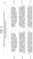
- Fig. 2 is a drawing schematically illustrating a flow of the method for correcting the misalignment of the camera by selectively using the information generated by itself and the information generated by other entities.
- the computing device 100 acquires at least one reference image through a camera on a subject vehicle. Thereafter, the computing device 100 performs first processes corresponding to steps of S02-1, S03-1 and S04-1, if circumstance information of the subject vehicle to be explained later corresponds to a first condition. Otherwise, the computing device 100 performs second processes corresponding to steps of S02-2, S03-2 and S04-2, if the circumstance information corresponds to a second condition. That is, the two kinds of processes, i.e., the first ones and the second ones illustrated in Fig. 2 , are selectively performed according to the circumstance information. However, it is possible for the two kinds of processes to be performed together in parallel, as the case may be.
- the computing device 100 instructs the first CNN 130 to apply at least one first CNN operation to the reference image, to thereby generate first reference data including information on reference lanes of the reference image. And, at the step of S03-1, the computing device 100 instructs the correction module 150 to generate at least one first angle error on the camera corresponding to the reference lanes by referring to the first reference data and vehicle coordinate data. Then, at the step of S04-1, the computing device 100 instructs a physical rotation module(not illustrated) on the subject vehicle to adjust an incorrect angle of the camera by referring to the first angle error.
- the incorrect angle may have been caused unwantedly due to external factors like physical collisions on the camera.
- the computing device 100 instructs the second CNN 140 to apply at least one second CNN operation to the reference image, to thereby generate second reference data including information on reference vehicles of the reference image. And, at the step of S03-2, the computing device 100 instructs the correction module 150 to generate at least one second angle error on the camera corresponding to the reference vehicles by referring to the second reference data and the vehicle coordinate data. Then, at the step of S04-2, the computing device 100 instructs the physical rotation module(not illustrated) on the subject vehicle to adjust the incorrect angle by referring to the second angle error.
- the circumstance information includes information on whether there are sufficient number of lanes around the subject vehicle or not, i.e., the number of the lanes being larger than a first threshold, and information on whether there are sufficient number of vehicles around the subject vehicle or not, i.e., the number of the vehicles being larger than a second threshold.
- the first condition of the circumstance information denotes a case when there are lanes more than the first threshold around the subject vehicle.
- the first processes are performed by using information on the reference lanes, thus the first condition of the circumstance information is necessary.
- the second condition of the circumstance information denotes a case when there are vehicles more than the second threshold around the subject vehicle.
- the second processes are performed by using information on the reference vehicles, thus the second condition of the circumstance information is necessary.
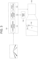
- Fig. 3 is a drawing schematically illustrating how a first angle error, to be used for correcting the misalignment of the camera by selectively using the information generated by itself and the information generated by other entities, is acquired.
- the computing device 100 generates the first angle error through the first CNN 130 and the correction module 150. Specifically, the computing device 100 instructs at least one first convolutional layer 131 in the first CNN 130 to apply at least one first convolutional operation to the reference image, to thereby generate at least one first reference feature map. Then, the computing device 100 instructs at least one first pooling layer 132 in the first CNN 130 to acquire first Region-Of-Interest information from a first Region Proposal Network(RPN) 134, and then to apply at least one first pooling operation to the first reference feature map, to thereby generate at least one first reference pooled feature map.
- RPN Region Proposal Network
- the computing device 100 instructs at least one first Fully-Connected(FC) layer 133 in the first CNN 130 to apply at least one first FC operation to the first reference pooled feature map, to thereby generate detection result on the reference lanes of the reference image as the first reference data.
- FC Fully-Connected
- Said processes are similar to a well-known structure of "Faster R-CNN" used for detecting objects on an image, thus a person in the art may easily understand the above explanations.
- the computing device 100 instructs the correction module 150 to map the reference lanes onto a coordinate plane corresponding to the vehicle coordinate data.
- the vehicle coordinate data includes information on camera parameters of the camera on the subject vehicle.
- the reference lanes may be mapped onto the coordinate plane with the location of the subject vehicle in its origin point, by using a well-known image processing scheme using the camera parameter.
- the computing device 100 finds a specific reference lane 152, among the reference lanes, which is the closest from the subject vehicle, and calculates a first difference angle between a prescribed reference axis 151 on the coordinate plane and the specific reference lane 152.
- the reference axis 151 may be an axis parallel to a straight line on the coordinate plane which is generated by setting a properly arranged lane parallel to the subject vehicle in an image photographed by the camera with an optimized angle.
- the correction module 150 outputs the first difference angle as the first angle error, and the computing device 100 instructs the physical rotation module to adjust the angle of the camera by referring to the first angle error.
- the computing device 100 may acquire driving information of the subject vehicle from a Controller Area Network(CAN) thereof, may determine whether the driving information corresponds to a condition A representing a situation that the subject vehicle drives straight continuously for a time of a third threshold or a condition B, which is opposite case of the condition A, and may instruct, if the driving information corresponds to the condition A, the first CNN 130 to apply the first CNN operation to the reference image in order to perform the first processes.
- CAN Controller Area Network
- Fig. 4 is a drawing schematically illustrating how a second angle error, to be used for correcting the misalignment of the camera by selectively using the information generated by itself and the information generated by other entities, is acquired.
- the computing device 100 generates the second angle error through the second CNN 140 and the correction module 150. Specifically, the computing device 100 instructs at least one second convolutional layer 141 in the second CNN 140 to apply at least one second convolutional operation to the reference image, to thereby generate at least one second reference feature map. Then, the computing device 100 instructs at least one second pooling layer 142 in the second CNN 140 to acquire second Region-Of-Interest information from a second RPN 144, and then to apply at least one second pooling operation to the second reference feature map, to thereby generate at least one second reference pooled feature map.
- the computing device 100 instructs at least one second FC layer 143 in the second CNN 140 to apply at least one second FC operation to the second reference pooled feature map, to thereby generate detection result on the reference vehicles of the reference image as the second reference data.
- the reference vehicles may be at least part of the vehicles around the subject vehicle which have been photographed on the reference image.
- a first reference vehicle 300, a second reference vehicle 400 and a third reference vehicle 500 which are located in front of the subject vehicle, may have been photographed as the reference vehicles.
- V2V communication vehicles which are at least part of the vehicles around the subject vehicle 200.
- N is an integer same as or larger than 1.
- a K-th specific V2V communication vehicle 600 and an L-th specific V2V communication vehicle 700 can be seen.
- K and L may be integers from 1 to N.
- the K-th and the L-th specific V2V communication vehicles 600 and 700 may calculate locations of their surrounding vehicles, such as the subject vehicle 200, the first reference vehicle 300, the second reference vehicle 400 and the third reference vehicle 500, in case their cameras are installed to their front parts.
- the K-th and the L-th specific V2V communication vehicle 600 and 700 may calculate locations of their surrounding vehicles, i.e., the subject vehicle 200, the first reference vehicle 300, the second reference vehicle 400 and the third reference vehicle 500, as K-th specific comparable data and L-th specific comparable data, and then deliver those to the computing device 100 in the subject vehicle 200.
- the comparable data including first to N-th specific comparable data can be acquired.
- the computing device 100 instructs the correction module 150 to generate each of two kinds of coordinates, i.e., image-based coordinates and communication-based coordinates, by referring to each of the second reference data and the comparable data. That is, the computing device 100 instructs the correction module 150 to generate the image-based coordinates on the coordinate plane representing one or more relative locations of the reference vehicles in relation to the subject vehicle, by referring to the second reference data.
- the image-based coordinates may denote the locations of the reference vehicles estimated by using the camera in the current state with the incorrect angle.
- the computing device 100 instructs the correction module 150 to generate the communication-based coordinates on the coordinate plane representing one or more relative locations of the surrounding vehicles of the V2V communication vehicles in relation to the subject vehicle by referring to the comparable data.
- Such communication-based coordinates may denote the locations of the surrounding vehicles of the V2V communication vehicles estimated by the V2V communication vehicles, and may be used for being compared with the image-based coordinates.
- the computing device 100 may instruct the correction module 150, by referring to information on a Field-Of-View(FOV) of the camera, the K-th specific comparable data and the L-th specific comparable data, to map the locations of K-th specific surrounding vehicles and L-th specific surrounding vehicles respectively located around the K-th specific V2V communication vehicle and the L-th specific V2V communication vehicle onto the coordinate plane, to thereby respectively generate one or more K-th initial coordinates and one or more L-th initial coordinates.
- FOV Field-Of-View
- the computing device 100 may instruct the correction module 150 to merge each of the initial coordinates corresponding to each of the surrounding vehicles of the V2V communication vehicles, to thereby generate the communication-based coordinates.
- the first to the N-th initial coordinates may include the K-th initial coordinates and the L-th initial coordinates.
- the K-th specific comparable data may include each of estimated coordinates of the subject vehicle 200, the first reference vehicle 300, the second reference vehicle 400 and the third reference vehicle 500, i.e., x 0 k y 0 k , x 1 k y 1 k , x 2 k y 2 k and x 3 k y 3 k respectively
- the L-th specific comparable data may include each of estimated coordinates of the subject vehicle 200, the first reference vehicle 300, the second reference vehicle 400 and the third reference vehicle 500, i.e., x 0 l y 0 l , x 1 l y 1 l , x 2 l y 2 l and x 3 l y 3 l respectively.
- Such estimated coordinates may be mapped onto the coordinate plane to become the K-th initial coordinates and the L-th initial coordinates. Since the origin point of the coordinate plane is the location of the subject vehicle 200, the K-th initial coordinates of the first to the third reference vehicles 300, 400 and 500 may be calculated by subtracting an estimated coordinate of the subject vehicle 200 from estimated coordinates of the first to the third reference vehicles 300, 400 and 500, and the L-th initial coordinates may be calculated in a similar way.
- the K-th initial coordinates for the first to the third reference vehicles 300, 400 and 500 may be calculated as x 1 k ⁇ x 0 k , y 1 k ⁇ y 0 k , x 2 k ⁇ x 0 k , y 2 k ⁇ y 0 k and x 3 k ⁇ x 0 k , y 3 k ⁇ y 0 k
- the L-th initial coordinates therefor may be calculated as x 1 l ⁇ x 0 l , y 1 l ⁇ y 0 l , x 2 l ⁇ x 0 l , y 2 l ⁇ y 0 l and x 3 l ⁇ x 0 l , y 3 l ⁇ y 0 l .
- some of the communication-based coordinates i.e., specific communication-based coordinates, for the first to the third reference vehicles 300, 400 and 500 may be generated by merging some of the initial coordinates, i.e., specific initial coordinates, corresponding to the first to the third reference vehicles 300, 400 and 500. How said specific initial coordinates are merged will be explained below, under an assumption that there are only the K-th initial coordinates and the L-th initial coordinates which correspond to the first to the third reference vehicles 300, 400 and 500.
- the specific part of the communication-based coordinates for the first to the third reference vehicles 300, 400 and 500 may be calculated as x 1 k ⁇ x 0 k 2 + x 1 l ⁇ x 0 l 2 , y 1 k ⁇ y 0 k 2 + y 1 l ⁇ y 0 l 2 , x 2 k ⁇ x 0 k 2 + x 2 l ⁇ x 0 l 2 , y 2 k ⁇ y 0 k 2 + y 2 l ⁇ y 0 l 2 and x 1 k ⁇ x 0 k 2 + x 1 l ⁇ x 0 l 2 , y 1 k ⁇ y 0 k 2 + y 1 l ⁇ y 0 l 2 , by averaging each of pairs of each of the K-th initial coordinates and each of the L-th initial coordinates corresponding to each of the first to the third reference vehicles 300,
- the computing device 100 After the communication-based coordinates are generated, the computing device 100 generates the second angle error by referring to the image-based coordinates and their corresponding communication-based coordinates. Specifically, the computing device 100 instructs the correction module 150 to calculate at least one second difference angle between (i) at least one first specific direct line including at least one specific communication-based coordinate of at least one specific reference vehicle which is included in both of the reference vehicles and the surrounding vehicles, and the origin point of the coordinate plane and (ii) at least one second specific direct line including at least one specific image-based coordinate of at least one specific reference vehicle and the origin point of the coordinate plane, and output the second difference angle as the second angle error.
- Fig. 4 will be again referred to.
- a first, a second and a third specific communication-based coordinates 301, 401 and 501 and a first, a second and a third specific image-based coordinates 302, 402 and 502 for the first, the second and the third reference vehicles 300, 400 and 500 may be seen, and it may be seen that difference angles ⁇ 1 , ⁇ 2 and ⁇ 3 between first lines including the first, the second and the third specific communication-based coordinates and second lines including the first, the second and the third specific image-based coordinates are calculated.
- the second angle error may be calculated as an average of the difference angles.
- second angle eror 1 M ⁇ k M ⁇ k sin ⁇ 1 x i k y c k ⁇ y i k x c k x i k y i k x c k y c k
- M may denote the number of the specific reference vehicles which are included in both of the reference vehicles and the surrounding vehicles of the V2V communication vehicles, and ( i k , y i k ) may denote a K-th specific image-based coordinate of a K-th specific reference vehicle. Also, ( x v k , y v k ) may denote a K-th specific communication-based coordinate thereof, and ⁇ k may denote a weight for the K-th specific reference vehicle.
- the second processes explained so far may be performed when a difference between a timing of the reference image being acquired and a timing of the comparable data being generated is smaller than a fourth threshold. Also, an accuracy of the second processes may be dropped when the subject vehicle is not driving straight, thus the second processes, similar to the first processes, may be performed when the driving information of the subject vehicle corresponds to the condition A for the straight driving.
- the present disclosure has an effect of providing a method for detecting and adjusting a misalignment of a camera by selectively using information generated by itself and information generated by other entities, to thereby reduce dangers of autonomous driving caused by external factors.
- the present disclosure has another effect of providing a method for integrating each of pieces of said information generated by each of other vehicles to generate comparable data to be compared with the information generated by itself, to thereby correct the misalignment of the camera.
- the embodiments of the present disclosure as explained above can be implemented in a form of executable program command through a variety of computer means recordable to computer readable media.
- the computer readable media may include solely or in combination, program commands, data files, and data structures.
- the program commands recorded to the media may be components specially designed for the present disclosure or may be usable to a skilled human in a field of computer software.
- Computer readable media include magnetic media such as hard disk, floppy disk, and magnetic tape, optical media such as CD-ROM and DVD, magneto-optical media such as floptical disk and hardware devices such as ROM, RAM, and flash memory specially designed to store and carry out program commands.
- Program commands include not only a machine language code made by a complier but also a high level code that can be used by an interpreter etc., which is executed by a computer.
- the aforementioned hardware device can work as more than a software module to perform the action of the present disclosure and they can do the same in the opposite case.
Landscapes
- Engineering & Computer Science (AREA)
- Theoretical Computer Science (AREA)
- Physics & Mathematics (AREA)
- General Physics & Mathematics (AREA)
- Multimedia (AREA)
- Biomedical Technology (AREA)
- General Health & Medical Sciences (AREA)
- Health & Medical Sciences (AREA)
- Life Sciences & Earth Sciences (AREA)
- Molecular Biology (AREA)
- Artificial Intelligence (AREA)
- Evolutionary Computation (AREA)
- Mathematical Physics (AREA)
- Computing Systems (AREA)
- Software Systems (AREA)
- General Engineering & Computer Science (AREA)
- Biophysics (AREA)
- Computational Linguistics (AREA)
- Data Mining & Analysis (AREA)
- Signal Processing (AREA)
- Computer Vision & Pattern Recognition (AREA)
- Biodiversity & Conservation Biology (AREA)
- Quality & Reliability (AREA)
- Computer Networks & Wireless Communication (AREA)
- Traffic Control Systems (AREA)
- Image Analysis (AREA)
- Control Of Driving Devices And Active Controlling Of Vehicle (AREA)
Claims (6)
- Procédé destiné à corriger un angle incorrect d'une caméra orientée involontairement sur un véhicule sujet (200) à l'aide au moins d'une partie d'informations primaires générées par le véhicule sujet lui-même et d'informations secondaires générées par d'autres véhicules autour du véhicule sujet, dans lequel au moins les informations parmi les informations primaires et les informations secondaires sont sélectionnées à l'aide d'informations de circonstances sur l'environnement du véhicule sujet, à utiliser pour corriger l'angle incorrect, dans lequel les informations de circonstance incluent des informations sur le fait de savoir si oui ou non le nombre des voies est supérieur à un premier seuil et sur le fait de savoir si oui ou non le nombre des autres véhicules est supérieur à un second seuil, comprenant les étapes suivantes :(a) si au moins une image de référence est acquise par le biais d'une caméra sur le véhicule sujet (200), un dispositif informatique (100) réalise (i) un traitement pour ordonner, si les informations de circonstance correspondent à une première condition liée à des voies sur des routes, laquelle indique un cas où il y a plus de voies que le premier seuil autour du véhicule sujet, à un premier réseau de neurones à convolution (CNN, Convolutional Neural Network) (130) d'appliquer au moins une première opération CNN à l'image de référence, afin ainsi de générer des premières données de référence incluant des informations sur des voies de référence de l'image de référence, dans lequel les voies de référence sont des voies dans l'image de référence, et (ii) un traitement pour ordonner, si les informations de circonstance correspondent à une seconde condition liée à d'autres véhicules sur les routes, laquelle indique un cas où il y a plus de véhicules que le second seuil autour du véhicule sujet, à un second réseau CNN (140) d'appliquer au moins une seconde opération CNN à l'image de référence, afin ainsi de générer des secondes données de référence incluant des informations sur un ou plusieurs véhicules de référence (300, 400, 500) de l'image de référence, dans lequel les véhicules de référence (300, 400, 500) sont des véhicules dans l'image de référence ;(b) le dispositif informatique (100) ordonne à un module de correction (150) de réaliser (i) un traitement pour générer, si les informations de circonstance correspondent à la première condition, au moins une première erreur d'angle sur la caméra correspondant aux voies de référence en se référant aux premières données de référence et aux données de coordonnées de véhicule, lesquelles incluent des informations sur des paramètres de caméra de la caméra sur le véhicule sujet, et (ii) un traitement pour générer, si les informations de circonstance correspondent à la seconde condition, au moins une seconde erreur d'angle sur la caméra correspondant aux véhicules de référence (300, 400, 500) en se référant aux secondes données de référence et aux données de coordonnées de véhicule, et(c) le dispositif informatique (100) ordonne à un module de rotation physique sur le véhicule sujet (200) de réaliser (i) un traitement pour régler, si les informations de circonstance correspondent à la première condition, l'angle incorrect en se référant à la première erreur d'angle correspondant aux voies de référence, et (ii) un traitement pour régler, si les informations de circonstance correspondent à la seconde condition, l'angle incorrect en se référant à la seconde erreur d'angle correspondant aux véhicules de référence (300, 400, 500),dans lequel lors de l'étape (a), si les informations de circonstance correspondent à la première condition, le dispositif informatique (100) (i) ordonne à au moins une première couche de convolution (131) dans le premier CNN (130) d'appliquer au moins une première opération de convolution à l'image de référence, afin ainsi de générer au moins une première carte de caractéristiques de référence, (ii) ordonne à au moins une première couche de regroupement (132) dans le premier CNN (130) d'appliquer au moins une première opération de regroupement à la première carte de caractéristiques de référence, afin ainsi de générer au moins une première carte de caractéristiques regroupée de référence, et (iii) ordonne à au moins une première couche à interconnexion intégrale (FC, Fully Connected) (133) dans le premier CNN (130) d'appliquer au moins une première opération FC à la première carte de caractéristiques regroupée de référence, afin ainsi de générer un résultat de détection sur les voies de référence de l'image de référence comme premières données de référence,dans lequel lors de l'étape (b), si les informations de circonstance correspondent à la première condition, le dispositif informatique (100) ordonne au module de correction (150) de (i) cartographier les voies de référence sur un plan de coordonnées correspondant aux données de coordonnées de véhicule, en se référant aux données de coordonnées de véhicule, de (ii) calculer au moins un premier angle de différence entre un axe de référence (151) sur le plan de coordonnées et au moins une des voies de référence (152), et de (iii) produire le premier angle de différence comme la première erreur d'angle ;dans lequel lors de l'étape (a), le dispositif informatique (100), si les informations de circonstance correspondent à la seconde condition, (i) ordonne à au moins une seconde couche de convolution (141) dans le second réseau CNN (140) d'appliquer au moins une seconde opération de convolution à l'image de référence, afin ainsi de générer au moins une seconde carte de caractéristiques de référence, (ii) ordonne à au moins une seconde couche de regroupement (142) dans le second CNN (140) d'appliquer au moins une seconde opération de regroupement à la seconde carte de caractéristiques de référence, afin ainsi de générer au moins une seconde carte de caractéristiques regroupée de référence, et (iii) ordonne à au moins une seconde couche à interconnexion intégrale (FC, Fully Connected) (143) dans le second CNN (140) d'appliquer au moins une seconde opération FC à la seconde carte de caractéristiques regroupée de référence, afin ainsi de générer un résultat de détection sur les véhicules de référence (300, 400, 500) de l'image de référence comme seconde données de référence,dans lequel lors de l'étape (a), si les informations de circonstance correspondent à la seconde condition, parallèlement audit traitement de génération des secondes données de référence, le dispositif informatique (100) acquiert des données comparables à partir d'un ou de plusieurs véhicules à communication V2V (600, 700) situés plus près qu'un premier seuil du véhicule sujet (200) en réalisant des communications sans fil avec les véhicules à communication V2V (600, 700),dans lequel des Kièmes données comparables spécifiques, parmi les données comparables, acquises à partir d'un Kième véhicule à communication V2V spécifique parmi un premier à un Nième véhicule à communication spécifiques V2V (600, 700) dans les véhicules à communication V2V (600, 700), incluent des informations, générées par le Kième véhicule à communication V2V spécifique, en des emplacements de ses Kièmes véhicules environnants spécifiques situés plus près qu'un second seuil par rapport au véhicule sujet (200), etdans lequel lors de l'étape (b), si les informations de circonstance correspondent à la seconde condition, le dispositif informatique (100) ordonne au module de correction (150) de (i) réaliser (i-1) un traitement pour générer une ou plusieurs coordonnées basées sur l'image (302, 402, 502) sur un plan de coordonnées correspondant aux données de coordonnées de véhicule représentant un ou plusieurs emplacements relatifs des véhicules de référence (300, 400, 500) par rapport au véhicule sujet (200) en se référant aux secondes données de référence, et (i-2) un traitement pour générer une ou plusieurs coordonnées basées sur la communication (301, 401, 501) sur le plan de coordonnées représentant un ou plusieurs emplacements relatifs de véhicules environnants des véhicules à communication V2V (600, 700) par rapport au véhicule sujet (200) en se référant aux données comparables, puis de (ii) générer la seconde erreur d'angle en se référant aux coordonnées basées sur l'image (302, 402, 502) et aux coordonnées basées sur la communication (301, 401, 501),dans lequel N indique le nombre de véhicules à communication V2V (600, 700), et K indique un entier de 1 à N,dans lequel lors de l'étape (b), le dispositif informatique (100) ordonne au module de correction (150) de calculer au moins un second angle de différence entre (i) au moins une première ligne directe spécifique incluant au moins une coordonnée basée sur la communication spécifique d'au moins un véhicule de référence spécifique, lequel est inclus à la fois dans les véhicules de référence (300, 400, 500) et les véhicules environnants, et un point d'origine du plan de coordonnées, et (ii) au moins une seconde ligne directe spécifique incluant au moins une coordonnée basée sur l'image spécifique d'au moins un véhicule de référence spécifique et le point d'origine du plan de coordonnées, et produire le second angle de différence comme la seconde erreur d'angle.
- Procédé selon la revendication 1, dans lequel lors de l'étape (b), si les informations de circonstance correspondent à la seconde condition, le dispositif informatique (100) ordonne au module de correction (150), en se référant aux informations sur un champ de vue (FOV, Field-Of-View) de la caméra et les kièmes données comparables spécifiques acquises à partir du Kième module de communication V2V spécifique, de (i) cartographier les emplacements de ses dits Kièmes véhicules environnants spécifiques estimés par le Kième véhicule à communication V2V spécifique sur le plan de coordonnées, afin ainsi de générer une ou plusieurs Kièmes coordonnées initiales, et (ii) générer les coordonnées basées sur la communication (301, 401, 501) des véhicules environnants en se référant à une ou plusieurs premières à une ou plusieurs Nièmes coordonnées initiales incluant les Kièmes coordonnées initiales.
- Procédé selon la revendication 1, dans lequel lors de l'étape (b), s'il y a une pluralité de (i) véhicules de référence spécifiques (300, 400 500) inclus à la fois dans les véhicules de référence (300, 400, 500) et les véhicules environnants, (ii) de coordonnées basées sur l'image spécifiques (302, 402, 502) correspondant aux véhicules de référence spécifiques (300, 400, 500), et (iii) de coordonnées basées sur la communication spécifiques (301, 401, 501) correspondant aux véhicules de référence spécifiques (300, 400, 500), le dispositif informatique (100) génère la seconde erreur d'angle en se référant à une formule suivante :

- Procédé selon la revendication 1, dans lequel lors de l'étape (a), si des informations de conduite du véhicule sujet (200) sont acquises à partir d'un réseau CAN (Controller Area Network) du véhicule sujet (200), le dispositif informatique (100) détermine si oui ou non les informations de conduite correspondent à une condition A pour une conduite droite ou une condition B pour une conduite non droite, et ordonne au premier CNN (130) ou au second CNN (140) d'appliquer la première opération CNN ou la seconde opération CNN à l'image de référence si les informations de conduite correspondent à la condition A.
- Dispositif informatique (100) destiné à corriger un angle incorrect d'une caméra orientée involontairement sur un véhicule sujet (200) à l'aide d'au moins une partie d'informations primaires générées par le véhicule sujet lui-même et d'informations secondaires générées par d'autres véhicules autour du véhicule sujet, dans lequel au moins des informations parmi les informations primaires et les informations secondaires sont sélectionnées à l'aide d'informations de circonstances sur l'environnement du véhicule sujet, à utiliser pour corriger l'angle incorrect, dans lequel les informations de circonstance incluent des informations sur le fait de savoir si oui ou non le nombre des voies est supérieur à un premier seuil et des informations sur le fait de savoir si oui ou non le nombre des autres véhicules est supérieur à un second seuil, comprenant :au moins une mémoire (115), laquelle stocke des instructions, etau moins un processeur (120) configuré pour exécuter les instructions pour réaliser des traitements pour : (I) si au moins une image de référence est acquise par le biais d'une caméra sur le véhicule sujet (200), ordonner, si les informations de circonstance correspondent à une première condition liée à des voies sur des routes, laquelle indique un cas où il y a plus de voies que le premier seuil autour du véhicule sujet (200), à un premier réseau de neurones à convolution (CNN, Convolutional Neural Network) (130) d'appliquer au moins une première opération CNN à l'image de référence, afin ainsi de générer des premières données de référence incluant des informations sur des voies de référence de l'image de référence, dans lequel les voies de référence sont des voies dans l'image de référence, et ordonner, si les informations de circonstance correspondent à une seconde condition liée à d'autres véhicules sur les routes, laquelle indique un cas où il y a plus de véhicules que le second seuil autour du véhicule sujet (200), à un second réseau CNN (140) d'appliquer au moins une seconde opération CNN à l'image de référence, afin ainsi de générer des secondes données de référence incluant des informations sur un ou plusieurs véhicules de référence (300, 400, 500) de l'image de référence, dans lequel les véhicules de référence (300, 400, 500) sont des véhicules dans l'image de référence ; (II) ordonner à un module de correction (150) de générer, si les informations de circonstance correspondent à la première condition, au moins une première erreur d'angle sur la caméra correspondant aux voies de référence en se référant aux premières données de référence et aux données de coordonnées de véhicule, lesquelles incluent des informations sur des paramètres de caméra de la caméra sur le véhicule sujet, et générer, si les informations de circonstance correspondent à la seconde condition, au moins une seconde erreur d'angle sur la caméra correspondant aux véhicules de référence (300, 400, 500) en se référant aux secondes données de référence et aux données de coordonnées de véhicule, et (III) ordonner à un module de rotation physique sur le véhicule sujet (200) de régler, si les informations de circonstance correspondent à la première condition, l'angle incorrect en se référant à la première erreur d'angle correspondant aux voies de référence, et régler, si les informations de circonstance correspondent à la seconde condition, l'angle incorrect en se référant à la seconde erreur d'angle correspondant aux véhicules de référence (300, 400, 500),dans lequel lors du traitement (I), si les informations de circonstance correspondent à la première condition, le processeur (120) (i) ordonne à au moins une première couche de convolution (131) dans le premier CNN (130) d'appliquer au moins une première opération de convolution à l'image de référence, afin ainsi de générer au moins une première carte de caractéristiques de référence, (ii) ordonne à au moins une première couche de regroupement (132) dans le premier CNN (130) d'appliquer au moins une première opération de regroupement à la première carte de caractéristiques de référence, afin ainsi de générer au moins une première carte de caractéristiques regroupée de référence, et (iii) ordonne à au moins une première couche à interconnexion intégrale (FC, Fully Connected) (133) dans le premier CNN (130) d'appliquer au moins une première opération FC à la première carte de caractéristiques regroupée de référence, afin ainsi de générer un résultat de détection sur les voies de référence de l'image de référence comme premières données de référence,dans lequel lors du traitement (II), si les informations de circonstance correspondent à la première condition, le processeur (120) ordonne au module de correction (150) de (i) cartographier les voies de référence sur un plan de coordonnées correspondant aux données de coordonnées de véhicule, en se référant aux données de coordonnées de véhicule, de (ii) calculer au moins un premier angle de différence entre un axe de référence (151) sur le plan de coordonnées et au moins une des voies de référence (152), et de (iii) produire le premier angle de différence comme la première erreur d'angle ;dans lequel lors du traitement (I), si les informations de circonstance correspondent à la seconde condition, le processeur (120) (i) ordonne à au moins une seconde couche de convolution (141) dans le second réseau CNN (140) d'appliquer au moins une seconde opération de convolution à l'image de référence, afin ainsi de générer au moins une seconde carte de caractéristiques de référence, (ii) ordonne à au moins une seconde couche de regroupement (142) dans le second CNN (140) d'appliquer au moins une seconde opération de regroupement à la seconde carte de caractéristiques de référence, afin ainsi de générer au moins une seconde carte de caractéristiques regroupée de référence, et (iii) ordonne à au moins une seconde couche à interconnexion intégrale (FC, Fully Connected) (143) dans le second CNN (140) d'appliquer au moins une seconde opération FC à la seconde carte de caractéristiques regroupée de référence, afin ainsi de générer un résultat de détection sur les véhicules de référence (300, 400, 500) de l'image de référence comme seconde données de référence,dans lequel lors du traitement (I), si les informations de circonstance correspondent à la seconde condition, parallèlement audit traitement de génération des secondes données de référence, le processeur (120) acquiert des données comparables à partir d'un ou de plusieurs véhicules à communication V2V (600, 700) situés plus près qu'un premier seuil par rapport au véhicule sujet (200) en réalisant des communications sans fil avec les véhicules à communication V2V (600, 700),dans lequel des Kièmes données comparables spécifiques, parmi les données comparables, acquises à partir d'un Kième véhicule à communication V2V spécifique parmi un premier à un Nième véhicule à communication V2V spécifiques (600, 700) dans les véhicules à communication V2V (600, 700), incluent des informations, générées par le Kième véhicule à communication V2V spécifique, en des emplacements de ses Kièmes véhicules environnants spécifiques situés plus près qu'un second seuil par rapport au véhicule sujet (200), etdans lequel lors du traitement (II), si les informations de circonstance correspondent à la seconde condition, le processeur (120) ordonne au module de correction (150) de (i) réaliser (i-1) un traitement pour générer une ou plusieurs coordonnées basées sur l'image (302, 402, 502) sur un plan de coordonnées correspondant aux données de coordonnées de véhicule représentant un ou plusieurs emplacements relatifs des véhicules de référence (300, 400, 500) par rapport au véhicule sujet (200) en se référant aux secondes données de référence, et (i-2) un traitement pour générer une ou plusieurs coordonnées basées sur la communication (301, 401, 501) sur le plan de coordonnées représentant un ou plusieurs emplacements relatifs des véhicules environnants des véhicules à communication V2V (600, 700) par rapport au véhicule sujet (200) en se référant aux données comparables, puis de (ii) générer la seconde erreur d'angle en se référant aux coordonnées basées sur l'image (302, 402, 502) et aux coordonnées basées sur la communication (301, 401, 501),dans lequel N indique le nombre de véhicules à communication V2V (600, 700), et K indique un entier de 1 à N,dans lequel lors du traitement (II), le processeur (120) ordonne au module de correction (150) de calculer au moins un second angle de différence entre (i) au moins une première ligne directe spécifique incluant au moins une coordonnée basée sur la communication spécifique d'au moins un véhicule de référence spécifique, lequel est inclus à la fois dans les véhicules de référence (300, 400, 500) et les véhicules environnants, et un point d'origine du plan de coordonnées, et (ii) au moins une seconde ligne directe spécifique incluant au moins une coordonnée basée sur la communication spécifique d'au moins un véhicule de référence spécifique et le point d'origine du plan de coordonnées, et produire le second angle de différence comme la seconde erreur d'angle.
- Dispositif selon la revendication 5, dans lequel lors du traitement (II), si les informations de circonstance correspondent à la seconde condition, le processeur (120) ordonne au module de correction (150), en se référant aux informations sur un champ de vue (FOV, Field-Of-View) de la caméra et les Kièmes données comparables spécifiques acquises à partir du Kième module de communication V2V spécifique, de (i) cartographier les emplacements de ses dits Kièmes véhicules environnants spécifiques estimés par le Kième véhicule à communication V2V spécifique sur le plan de coordonnées, afin ainsi de générer une ou plusieurs Kièmes coordonnées initiales, et de (ii) générer les coordonnées basées sur la communication (301, 401, 501) des véhicules environnants en se référant à une ou plusieurs premières à une ou plusieurs Nièmes coordonnées initiales incluant les Kièmes coordonnées initiales.
Applications Claiming Priority (2)
| Application Number | Priority Date | Filing Date | Title |
|---|---|---|---|
| US201962799386P | 2019-01-31 | 2019-01-31 | |
| US16/740,165 US10728461B1 (en) | 2019-01-31 | 2020-01-10 | Method for correcting misalignment of camera by selectively using information generated by itself and information generated by other entities and device using the same |
Publications (3)
| Publication Number | Publication Date |
|---|---|
| EP3702964A1 EP3702964A1 (fr) | 2020-09-02 |
| EP3702964B1 true EP3702964B1 (fr) | 2024-12-18 |
| EP3702964C0 EP3702964C0 (fr) | 2024-12-18 |
Family
ID=69187605
Family Applications (1)
| Application Number | Title | Priority Date | Filing Date |
|---|---|---|---|
| EP20153035.9A Active EP3702964B1 (fr) | 2019-01-31 | 2020-01-22 | Procédé de correction de désalignement de caméra par utilisation sélective d'informations générées par lui-même et d'informations générées par d'autres entités d'autres et dispositif l'utilisant |
Country Status (5)
| Country | Link |
|---|---|
| US (1) | US10728461B1 (fr) |
| EP (1) | EP3702964B1 (fr) |
| JP (1) | JP6856855B2 (fr) |
| KR (1) | KR102373492B1 (fr) |
| CN (1) | CN111510704B (fr) |
Families Citing this family (6)
| Publication number | Priority date | Publication date | Assignee | Title |
|---|---|---|---|---|
| KR102854951B1 (ko) * | 2019-12-11 | 2025-09-04 | 현대자동차주식회사 | 양방향 차량상태정보 제공이 가능한 정보공유 플랫폼, 이를 갖는 시스템, 그리고 이의 방법 |
| JP7291953B2 (ja) * | 2020-07-27 | 2023-06-16 | 株式会社ニューギン | 遊技機 |
| CN113382171B (zh) * | 2021-06-21 | 2023-03-24 | 车路通科技(成都)有限公司 | 一种交通摄像头自动校正方法、装置、设备及介质 |
| KR102612353B1 (ko) * | 2021-09-02 | 2023-12-12 | 렉스젠(주) | 영상 분석 시스템 및 그에 관한 방법 |
| JP7769521B2 (ja) * | 2021-11-16 | 2025-11-13 | 株式会社Subaru | 自車両位置情報取得装置、自車両位置情報取得システムおよび自車両位置情報取得方法 |
| AU2023202005B1 (en) | 2023-03-31 | 2024-04-04 | Canva Pty Ltd | Image rotation |
Family Cites Families (20)
| Publication number | Priority date | Publication date | Assignee | Title |
|---|---|---|---|---|
| US7774113B2 (en) * | 2002-04-10 | 2010-08-10 | Trw Limited | Cameras to determine vehicle heading |
| JP4039357B2 (ja) * | 2003-11-10 | 2008-01-30 | トヨタ自動車株式会社 | 車両搭載カメラの光軸調整方法 |
| US7706978B2 (en) * | 2005-09-02 | 2010-04-27 | Delphi Technologies, Inc. | Method for estimating unknown parameters for a vehicle object detection system |
| US8017898B2 (en) * | 2007-08-17 | 2011-09-13 | Magna Electronics Inc. | Vehicular imaging system in an automatic headlamp control system |
| CN103582907B (zh) * | 2011-06-13 | 2016-07-20 | 日产自动车株式会社 | 车载用图像识别装置及车道识别方法 |
| KR102047280B1 (ko) * | 2012-09-27 | 2019-11-21 | 한국전자통신연구원 | 카메라 방향 제어를 이용한 차선 추종 장치 및 방법 |
| JP2014228943A (ja) * | 2013-05-20 | 2014-12-08 | 日本電産エレシス株式会社 | 車両用外界センシング装置、その軸ズレ補正プログラム及びその軸ズレ補正方法 |
| FR3014553A1 (fr) * | 2013-12-11 | 2015-06-12 | Parrot | Procede de calibration angulaire de la position d'une camera video embarquee dans un vehicule automobile |
| US10909721B2 (en) * | 2016-06-29 | 2021-02-02 | Seeing Machines Limited | Systems and methods for identifying pose of cameras in a scene |
| KR101979422B1 (ko) * | 2017-02-01 | 2019-05-16 | 주식회사 만도 | 카메라 시스템 및 카메라 시스템의 캘리브레이션정보 조정방법 |
| US10692244B2 (en) * | 2017-10-06 | 2020-06-23 | Nvidia Corporation | Learning based camera pose estimation from images of an environment |
| US10657390B2 (en) * | 2017-11-27 | 2020-05-19 | Tusimple, Inc. | System and method for large-scale lane marking detection using multimodal sensor data |
| CN108107897B (zh) * | 2018-01-11 | 2021-04-16 | 驭势科技(北京)有限公司 | 实时传感器控制方法及装置 |
| CN108639065B (zh) * | 2018-05-15 | 2019-09-27 | 辽宁工业大学 | 一种基于视觉的车辆安全行驶控制方法 |
| US10298910B1 (en) * | 2018-06-29 | 2019-05-21 | Zoox, Inc. | Infrastructure free intrinsic calibration |
| US10733761B2 (en) * | 2018-06-29 | 2020-08-04 | Zoox, Inc. | Sensor calibration |
| WO2020014683A1 (fr) * | 2018-07-13 | 2020-01-16 | Kache.AI | Systèmes et procédés de détection autonome d'objet et de suivi de véhicule |
| US10845815B2 (en) * | 2018-07-27 | 2020-11-24 | GM Global Technology Operations LLC | Systems, methods and controllers for an autonomous vehicle that implement autonomous driver agents and driving policy learners for generating and improving policies based on collective driving experiences of the autonomous driver agents |
| US10503174B1 (en) * | 2019-01-31 | 2019-12-10 | StradVision, Inc. | Method and device for optimized resource allocation in autonomous driving on the basis of reinforcement learning using data from lidar, radar, and camera sensor |
| CN110020651B (zh) * | 2019-04-19 | 2022-07-08 | 福州大学 | 基于深度学习网络的车牌检测定位方法 |
-
2020
- 2020-01-10 US US16/740,165 patent/US10728461B1/en active Active
- 2020-01-20 KR KR1020200007632A patent/KR102373492B1/ko active Active
- 2020-01-22 EP EP20153035.9A patent/EP3702964B1/fr active Active
- 2020-01-23 CN CN202010077079.3A patent/CN111510704B/zh active Active
- 2020-01-27 JP JP2020011164A patent/JP6856855B2/ja active Active
Also Published As
| Publication number | Publication date |
|---|---|
| JP6856855B2 (ja) | 2021-04-14 |
| JP2020126647A (ja) | 2020-08-20 |
| KR20200095379A (ko) | 2020-08-10 |
| CN111510704A (zh) | 2020-08-07 |
| KR102373492B1 (ko) | 2022-03-14 |
| EP3702964A1 (fr) | 2020-09-02 |
| US10728461B1 (en) | 2020-07-28 |
| CN111510704B (zh) | 2021-12-24 |
| EP3702964C0 (fr) | 2024-12-18 |
| US20200252550A1 (en) | 2020-08-06 |
Similar Documents
| Publication | Publication Date | Title |
|---|---|---|
| EP3702964B1 (fr) | Procédé de correction de désalignement de caméra par utilisation sélective d'informations générées par lui-même et d'informations générées par d'autres entités d'autres et dispositif l'utilisant | |
| EP3690727B1 (fr) | Procédé et dispositif d'apprentissage de fusion de capteur pour intégrer des informations acquises par radar pouvant estimer la distance et informations acquises par une caméra pour ainsi améliorer un réseau neuronal de support de conduite autonome et procédé et dispositif de test les utilisant | |
| EP3690817B1 (fr) | Procédé permettant de fournir une estimation fiable de la distance d'un objet en fonction d'une camera en effectuant un calibrage plus précis du tangage de la camera en fusionnant les informations acquises par la camera et les informations acquises par une communication v2v et dispositif utilisant ce procédé | |
| KR102221695B1 (ko) | 자율주행을 위한 고정밀 지도의 업데이트 장치 및 방법 | |
| EP3690730A2 (fr) | Procédé d'apprentissage de support de conduite autonome sans danger d'accident par évaluation des mouvements d'objets environnants par fusion d'informations provenant de sources multiples, dispositif d'apprentissage, procédé et dispositif d'essai l'utilisant | |
| CN114821517B (zh) | 用于学习神经网络以确定环境中车辆姿态的方法和系统 | |
| CN104848858B (zh) | 二维码以及用于机器人的视觉-惯性组合导航系统及方法 | |
| EP3690400B1 (fr) | Procédé et dispositif de localisation de véhicule ego pour mettre à jour une carte hd en utilisant la fusion d'informations v2x | |
| EP3690397B1 (fr) | Procédé et dispositif de localisation de véhicule autonome pour la planification d'un itinéraire à l'aide d'une détection de points de repère axée sur l'attention | |
| CN109101957B (zh) | 双目立体数据处理方法、装置、智能驾驶设备及存储介质 | |
| KR20200001471A (ko) | 차선 정보 검출 장치, 방법 및 이러한 방법을 수행하도록 프로그램된 컴퓨 프로그램을 저장하는 컴퓨터 판독가능한 기록매체 | |
| EP3690396B1 (fr) | Procédé et dispositif permettant de fournir un système d'aide avancé aux piétons afin de protéger les piétons distraits par leur smartphone | |
| US20170344836A1 (en) | Method and system for robust curb and bump detection from front or rear monocular cameras | |
| CN115790568B (zh) | 基于语义信息的地图生成方法及相关设备 | |
| KR20200120402A (ko) | 차량의 추정 위치 획득 장치 및 방법 | |
| CN114019947B (zh) | 一种车辆在路口处的行驶控制方法、系统及计算机可读存储介质 | |
| CN112215214A (zh) | 调整智能车载终端的摄像头偏移的方法及系统 | |
| Rasmussen | RoadCompass: following rural roads with vision+ ladar using vanishing point tracking | |
| KR101738425B1 (ko) | 다차선 검출을 위한 관심 영역 설정 장치 및 방법 | |
| Wang et al. | Heterogeneous stereo: A human vision inspired method for general robotics sensing | |
| 後方カメラ用画像処理技術 et al. | Image processing technology for rear view camera (1): Development of lane detection system | |
| US12223745B1 (en) | Pavement element annotation method for point cloud data with fusion of height, device for constructing and pre-annotation point cloud data with fusion of height, electronic device and computer-readable storage medium | |
| JP7754877B2 (ja) | 軌跡情報収集装置、軌跡情報収集方法及び軌跡情報収集用コンピュータプログラム | |
| JP7564742B2 (ja) | 情報処理装置及び情報処理方法 | |
| CN120668113A (zh) | 一种无人机拒止引导降落方法及装置 |
Legal Events
| Date | Code | Title | Description |
|---|---|---|---|
| PUAI | Public reference made under article 153(3) epc to a published international application that has entered the european phase |
Free format text: ORIGINAL CODE: 0009012 |
|
| STAA | Information on the status of an ep patent application or granted ep patent |
Free format text: STATUS: REQUEST FOR EXAMINATION WAS MADE |
|
| 17P | Request for examination filed |
Effective date: 20200122 |
|
| AK | Designated contracting states |
Kind code of ref document: A1 Designated state(s): AL AT BE BG CH CY CZ DE DK EE ES FI FR GB GR HR HU IE IS IT LI LT LU LV MC MK MT NL NO PL PT RO RS SE SI SK SM TR |
|
| AX | Request for extension of the european patent |
Extension state: BA ME |
|
| RBV | Designated contracting states (corrected) |
Designated state(s): AL AT BE BG CH CY CZ DE DK EE ES FI FR GB GR HR HU IE IS IT LI LT LU LV MC MK MT NL NO PL PT RO RS SE SI SK SM TR |
|
| STAA | Information on the status of an ep patent application or granted ep patent |
Free format text: STATUS: EXAMINATION IS IN PROGRESS |
|
| 17Q | First examination report despatched |
Effective date: 20220510 |
|
| REG | Reference to a national code |
Ref country code: DE Ref legal event code: R079 Free format text: PREVIOUS MAIN CLASS: G06K0009030000 Ipc: G06V0020590000 Ref document number: 602020043213 Country of ref document: DE |
|
| GRAP | Despatch of communication of intention to grant a patent |
Free format text: ORIGINAL CODE: EPIDOSNIGR1 |
|
| STAA | Information on the status of an ep patent application or granted ep patent |
Free format text: STATUS: GRANT OF PATENT IS INTENDED |
|
| RIC1 | Information provided on ipc code assigned before grant |
Ipc: H04N 17/00 20060101ALI20240725BHEP Ipc: H04N 23/695 20230101ALI20240725BHEP Ipc: G06N 3/045 20230101ALI20240725BHEP Ipc: G06V 10/98 20220101ALI20240725BHEP Ipc: G06V 10/44 20220101ALI20240725BHEP Ipc: G06V 10/24 20220101ALI20240725BHEP Ipc: G06T 7/80 20170101ALI20240725BHEP Ipc: G06V 20/56 20220101ALI20240725BHEP Ipc: G06V 20/59 20220101AFI20240725BHEP |
|
| INTG | Intention to grant announced |
Effective date: 20240813 |
|
| RIN1 | Information on inventor provided before grant (corrected) |
Inventor name: CHO, HOJIN Inventor name: JE, HONGMO Inventor name: JEONG, KYUNGJOONG Inventor name: JANG, TAEWOONG Inventor name: LEE, HYUNGSOO Inventor name: LEE, MYEONG-CHUN Inventor name: RYU, WOOJU Inventor name: YEO, DONGHUN Inventor name: SHIN, DONGSOO Inventor name: SUNG, MYUNGCHUL Inventor name: BOO, SUKHOON Inventor name: NAM, WOONHYUN Inventor name: KIM, HAK-KYOUNG Inventor name: KIM, YONGJOONG Inventor name: KIM, KYE-HYEON |
|
| GRAS | Grant fee paid |
Free format text: ORIGINAL CODE: EPIDOSNIGR3 |
|
| GRAA | (expected) grant |
Free format text: ORIGINAL CODE: 0009210 |
|
| STAA | Information on the status of an ep patent application or granted ep patent |
Free format text: STATUS: THE PATENT HAS BEEN GRANTED |
|
| AK | Designated contracting states |
Kind code of ref document: B1 Designated state(s): AL AT BE BG CH CY CZ DE DK EE ES FI FR GB GR HR HU IE IS IT LI LT LU LV MC MK MT NL NO PL PT RO RS SE SI SK SM TR |
|
| REG | Reference to a national code |
Ref country code: CH Ref legal event code: EP |
|
| REG | Reference to a national code |
Ref country code: DE Ref legal event code: R096 Ref document number: 602020043213 Country of ref document: DE |
|
| REG | Reference to a national code |
Ref country code: IE Ref legal event code: FG4D |
|
| U01 | Request for unitary effect filed |
Effective date: 20250110 |
|
| U07 | Unitary effect registered |
Designated state(s): AT BE BG DE DK EE FI FR IT LT LU LV MT NL PT RO SE SI Effective date: 20250117 |
|
| U20 | Renewal fee for the european patent with unitary effect paid |
Year of fee payment: 6 Effective date: 20250121 |
|
| PG25 | Lapsed in a contracting state [announced via postgrant information from national office to epo] |
Ref country code: HR Free format text: LAPSE BECAUSE OF FAILURE TO SUBMIT A TRANSLATION OF THE DESCRIPTION OR TO PAY THE FEE WITHIN THE PRESCRIBED TIME-LIMIT Effective date: 20241218 |
|
| PG25 | Lapsed in a contracting state [announced via postgrant information from national office to epo] |
Ref country code: NO Free format text: LAPSE BECAUSE OF FAILURE TO SUBMIT A TRANSLATION OF THE DESCRIPTION OR TO PAY THE FEE WITHIN THE PRESCRIBED TIME-LIMIT Effective date: 20250318 |
|
| PG25 | Lapsed in a contracting state [announced via postgrant information from national office to epo] |
Ref country code: GR Free format text: LAPSE BECAUSE OF FAILURE TO SUBMIT A TRANSLATION OF THE DESCRIPTION OR TO PAY THE FEE WITHIN THE PRESCRIBED TIME-LIMIT Effective date: 20250319 |
|
| PG25 | Lapsed in a contracting state [announced via postgrant information from national office to epo] |
Ref country code: RS Free format text: LAPSE BECAUSE OF FAILURE TO SUBMIT A TRANSLATION OF THE DESCRIPTION OR TO PAY THE FEE WITHIN THE PRESCRIBED TIME-LIMIT Effective date: 20250318 |
|
| PG25 | Lapsed in a contracting state [announced via postgrant information from national office to epo] |
Ref country code: SM Free format text: LAPSE BECAUSE OF FAILURE TO SUBMIT A TRANSLATION OF THE DESCRIPTION OR TO PAY THE FEE WITHIN THE PRESCRIBED TIME-LIMIT Effective date: 20241218 |
|
| PG25 | Lapsed in a contracting state [announced via postgrant information from national office to epo] |
Ref country code: PL Free format text: LAPSE BECAUSE OF FAILURE TO SUBMIT A TRANSLATION OF THE DESCRIPTION OR TO PAY THE FEE WITHIN THE PRESCRIBED TIME-LIMIT Effective date: 20241218 |
|
| PG25 | Lapsed in a contracting state [announced via postgrant information from national office to epo] |
Ref country code: ES Free format text: LAPSE BECAUSE OF FAILURE TO SUBMIT A TRANSLATION OF THE DESCRIPTION OR TO PAY THE FEE WITHIN THE PRESCRIBED TIME-LIMIT Effective date: 20241218 |
|
| PG25 | Lapsed in a contracting state [announced via postgrant information from national office to epo] |
Ref country code: IS Free format text: LAPSE BECAUSE OF FAILURE TO SUBMIT A TRANSLATION OF THE DESCRIPTION OR TO PAY THE FEE WITHIN THE PRESCRIBED TIME-LIMIT Effective date: 20250418 |
|
| PG25 | Lapsed in a contracting state [announced via postgrant information from national office to epo] |
Ref country code: SK Free format text: LAPSE BECAUSE OF FAILURE TO SUBMIT A TRANSLATION OF THE DESCRIPTION OR TO PAY THE FEE WITHIN THE PRESCRIBED TIME-LIMIT Effective date: 20241218 |
|
| PG25 | Lapsed in a contracting state [announced via postgrant information from national office to epo] |
Ref country code: CZ Free format text: LAPSE BECAUSE OF FAILURE TO SUBMIT A TRANSLATION OF THE DESCRIPTION OR TO PAY THE FEE WITHIN THE PRESCRIBED TIME-LIMIT Effective date: 20241218 |
|
| REG | Reference to a national code |
Ref country code: CH Ref legal event code: PL |
|
| PG25 | Lapsed in a contracting state [announced via postgrant information from national office to epo] |
Ref country code: MC Free format text: LAPSE BECAUSE OF FAILURE TO SUBMIT A TRANSLATION OF THE DESCRIPTION OR TO PAY THE FEE WITHIN THE PRESCRIBED TIME-LIMIT Effective date: 20241218 |
|
| PG25 | Lapsed in a contracting state [announced via postgrant information from national office to epo] |
Ref country code: CH Free format text: LAPSE BECAUSE OF NON-PAYMENT OF DUE FEES Effective date: 20250131 |
|
| PLBE | No opposition filed within time limit |
Free format text: ORIGINAL CODE: 0009261 |
|
| STAA | Information on the status of an ep patent application or granted ep patent |
Free format text: STATUS: NO OPPOSITION FILED WITHIN TIME LIMIT |
|
| 26N | No opposition filed |
Effective date: 20250919 |
|
| GBPC | Gb: european patent ceased through non-payment of renewal fee |
Effective date: 20250318 |
|
| PG25 | Lapsed in a contracting state [announced via postgrant information from national office to epo] |
Ref country code: GB Free format text: LAPSE BECAUSE OF NON-PAYMENT OF DUE FEES Effective date: 20250318 |
|
| PG25 | Lapsed in a contracting state [announced via postgrant information from national office to epo] |
Ref country code: IE Free format text: LAPSE BECAUSE OF NON-PAYMENT OF DUE FEES Effective date: 20250122 |
|
| U20 | Renewal fee for the european patent with unitary effect paid |
Year of fee payment: 7 Effective date: 20260122 |