EP3703206A1 - Boîte d'installation ainsi qu'unité d'installation dotée d'une telle boîte d'installation et d'un tuyau d'installation - Google Patents
Boîte d'installation ainsi qu'unité d'installation dotée d'une telle boîte d'installation et d'un tuyau d'installation Download PDFInfo
- Publication number
- EP3703206A1 EP3703206A1 EP20158372.1A EP20158372A EP3703206A1 EP 3703206 A1 EP3703206 A1 EP 3703206A1 EP 20158372 A EP20158372 A EP 20158372A EP 3703206 A1 EP3703206 A1 EP 3703206A1
- Authority
- EP
- European Patent Office
- Prior art keywords
- tear
- installation
- area
- contour
- pipe
- Prior art date
- Legal status (The legal status is an assumption and is not a legal conclusion. Google has not performed a legal analysis and makes no representation as to the accuracy of the status listed.)
- Granted
Links
Images

Classifications
-
- H—ELECTRICITY
- H02—GENERATION; CONVERSION OR DISTRIBUTION OF ELECTRIC POWER
- H02G—INSTALLATION OF ELECTRIC CABLES OR LINES, OR OF COMBINED OPTICAL AND ELECTRIC CABLES OR LINES
- H02G3/00—Installations of electric cables or lines or protective tubing therefor in or on buildings, equivalent structures or vehicles
- H02G3/02—Details
- H02G3/08—Distribution boxes; Connection or junction boxes
- H02G3/12—Distribution boxes; Connection or junction boxes for flush mounting
-
- H—ELECTRICITY
- H02—GENERATION; CONVERSION OR DISTRIBUTION OF ELECTRIC POWER
- H02G—INSTALLATION OF ELECTRIC CABLES OR LINES, OR OF COMBINED OPTICAL AND ELECTRIC CABLES OR LINES
- H02G3/00—Installations of electric cables or lines or protective tubing therefor in or on buildings, equivalent structures or vehicles
- H02G3/02—Details
- H02G3/06—Joints for connecting lengths of protective tubing or channels, to each other or to casings, e.g. to distribution boxes; Ensuring electrical continuity in the joint
- H02G3/0616—Joints for connecting tubing to casing
- H02G3/0691—Fixing tubing to casing by auxiliary means co-operating with indentations of the tubing, e.g. with tubing-convolutions
-
- H—ELECTRICITY
- H02—GENERATION; CONVERSION OR DISTRIBUTION OF ELECTRIC POWER
- H02G—INSTALLATION OF ELECTRIC CABLES OR LINES, OR OF COMBINED OPTICAL AND ELECTRIC CABLES OR LINES
- H02G3/00—Installations of electric cables or lines or protective tubing therefor in or on buildings, equivalent structures or vehicles
- H02G3/02—Details
- H02G3/08—Distribution boxes; Connection or junction boxes
- H02G3/081—Bases, casings or covers
- H02G3/083—Inlets
- H02G3/085—Inlets including knock-out or tear-out sections
-
- H—ELECTRICITY
- H02—GENERATION; CONVERSION OR DISTRIBUTION OF ELECTRIC POWER
- H02G—INSTALLATION OF ELECTRIC CABLES OR LINES, OR OF COMBINED OPTICAL AND ELECTRIC CABLES OR LINES
- H02G3/00—Installations of electric cables or lines or protective tubing therefor in or on buildings, equivalent structures or vehicles
- H02G3/02—Details
- H02G3/08—Distribution boxes; Connection or junction boxes
- H02G3/088—Dustproof, splashproof, drip-proof, waterproof, or flameproof casings or inlets
-
- H—ELECTRICITY
- H02—GENERATION; CONVERSION OR DISTRIBUTION OF ELECTRIC POWER
- H02G—INSTALLATION OF ELECTRIC CABLES OR LINES, OR OF COMBINED OPTICAL AND ELECTRIC CABLES OR LINES
- H02G3/00—Installations of electric cables or lines or protective tubing therefor in or on buildings, equivalent structures or vehicles
- H02G3/02—Details
- H02G3/04—Protective tubing or conduits, e.g. cable ladders or cable troughs
- H02G3/0462—Tubings, i.e. having a closed section
- H02G3/0468—Corrugated
Definitions
- the invention relates to an installation socket for electrical / electronic installations with a socket body serving to hold at least one electrical / electronic component, comprising a base, a circumferential wall and an assembly opening, which socket body has at least one pipe inlet covered with a soft plastic membrane for inserting the end section of an installation pipe .
- an installation unit is described with such an installation box and with an installation tube designed as a corrugated tube or corrugated hose inserted into at least one tube entry of the installation box, the soft plastic membrane having a bead formed by material thickening and a tear area enclosed by a tear contour at the position provided for a tube entry with a cross-sectional area which is smaller than the cross-sectional area of an installation pipe to be inserted therein, the tear area of which carries a tear handle for removing the tear area.
- Installation boxes are used for the installation of electrical and / or electronic devices in buildings.
- Such installation boxes are typically cavity wall boxes, and therefore installation boxes that are flush-mounted.
- Such installation boxes have a box body which is formed by a base, a circumferential wall and a mounting opening opposite the base.
- the mounting opening represents that opening in the can body through which the electrical / electronic devices are inserted therein.
- the wiring within the installation box and thus to the lines going out from it is also carried out via the installation opening.
- Sockets, equipment carriers, electrical / electronic switching devices such as dimmers or the like come into consideration as electrical / electronic installation devices.
- On the can body, at its wall section bordering the mounting opening is a radial direction molded support flange protruding outward.
- pipe entries are provided for introducing and removing lines into and out of the installation cavity provided by the can body. These openings are also used to connect installation pipes, for example corrugated plastic hoses, in which one or more cables are routed.
- Such installation boxes designed as cavity wall boxes are also installed in drywall.
- the pipe entries can be prepared using knockout parts.
- These break-out parts are plastic parts made of the same material as the can body itself, namely hard plastic, which are connected by break-off webs to the material of the can body surrounding such a tube entry.
- the required pipe entries are then opened by breaking out such a break-out part.
- each conduit entry is covered with a soft plastic membrane so that it is closed when not in use.
- an annular bead which defines the position at which a line or an installation pipe can be inserted.
- the membrane area located within the annular bead is torn, typically by pressing in this membrane area with the end face of the line to be inserted therein or the end face of an installation pipe to be inserted therein.
- cavity wall boxes are known in which a handling tab is molded onto the tear area.
- this handling tab is located centrally within the tear area. To open it, the handling tab has to be gripped manually and pulled until the tear area is removed. Sometimes a certain force has to be applied to tear out the tear area. If insufficient care is taken when tearing out the tear area, cracks extending through the bead can arise, which impairs the tightness of an installation pipe inserted into the opening created.
- a tear handle is molded onto the tear area.
- the manually applied tear force is applied starting in an apex area of the tear area adjoining the bead, which is why the location of a crack initiation is more defined than with other cavity wall boxes.
- the invention is therefore based on the object of developing an installation socket of the type described above in such a way that it is particularly suitable as a cavity wall socket and meets the requirements for windproofness when an installation pipe, in particular a corrugated pipe, is inserted into a pipe entry or corrugated hose as typical conduits for electrical Building installations is used and that is simplified in its handling compared to previously known cavity wall boxes of this type.
- the tear handle is designed with a concavely curved actuating surface for receiving a tear force acting transversely to the tear contour to tear the tear contour, the actuating surface of the tear handle being eccentric in relation to the direction of the to Tear provided force acting direction is arranged on the tear area and the tear handle extends to the area of the tear contour.
- a tear area is enclosed by a bead.
- This is the area or section of the soft plastic membrane that is removed from it in order to provide an opening for inserting a line or an installation pipe.
- the bead is located radially on the outside with respect to the tear area.
- a crack propagation within this tear area enclosed by the bead in the radial direction outward is limited by the bead as a result of its material thickening compared to the material thickness of the tear area.
- the side of the bead facing the tear area can serve as the tear contour.
- the tear contour is additionally provided by a material thinning that borders the tear area. In such a configuration, the tear area of the soft plastic membrane can be designed with a greater material thickness and thus more stable.
- the location of a crack initiation is specified by the tear contour forming a predetermined breaking point.
- the cross-sectional area of the tear area enclosed by the tear contour is also smaller than the cross-sectional area of an installation pipe to be inserted therein.
- an installation pipe inserted into the opening provided by removing the tear area is only possible with the bead widening.
- the elasticity of such a soft plastic membrane is used here. If the installation pipe is inserted into the pipe entry, if the bead rests on the outer surface of the installation pipe under prestress, which contributes to the windproofness of an installation pipe connected to such an installation socket.
- a special feature of this installation box is that the tear area of the soft plastic membrane spanning a pipe entry has an outwardly protruding tear handle.
- the tear handle is used to introduce a defined force - a tear force - into the tear area, so that in this way the tear area takes place through defined tearing of the soft plastic membrane along the tear contour.
- a defined tearing of the soft plastic membrane along the tear contour not only ensures a special windproofness of the opening provided by removing the tear area in relation to the outer surface of an installation pipe inserted therein, but also represents a further guarantee that the formation of cracks remains limited to the area of the tear contour In any case, crack formation does not take place through the bead surrounding the tear contour in the radial direction outward. The reason for this is that the crack is formed parallel to the extension of the bead and not in a direction transverse to it.
- the tear handle extends into the area of the tear contour. Due to the concave curvature and the eccentric arrangement of the actuating stop in the direction of the desired location of the crack initiation, the contour of the tear handle runs in the opposite direction to the contour of the bead or the tear contour following the course of the bead.
- a force applied to the actuation surface of the tear handle transversely to the plane of the tear area, namely with the direction of action towards the apex of the curved actuation surface of the tear handle, is passed on through this to the tear contour, because due to the material thickness of the tear handle, this does not apply to the applied force does not stretch significantly.
- one flat side thereof specifically the side facing the smaller tear area part, represents an actuation surface to which the force required to separate out the tear area is applied.
- the actuating surface for receiving a force required to tear the tear contour is located transversely to the acting opening force or tear force.
- the tear force is applied manually, for example by gripping such a web with two fingers and moving or adjusting it to generate the desired tensile stress. Due to the above-described geometry of the tear handle with its concavely curved actuating surface, the force required to separate out the tear area can, however, also be applied with a manually operated installation pipe to be inserted therein as an opening tool.
- the installation pipe is inserted with its end section through the opening created with this through the soft plastic membrane.
- the concave curvature of the actuating surface prevents the installation pipe from slipping sideways when an actuating force acting on the tear handle is exerted.
- the radius of curvature of the actuating surface typically corresponds at least approximately to the radius of the jacket surface of an installation pipe to be inserted through the pipe entry.
- the tear handle is supported on the upper side of the tear area, for example by support structures.
- one or more support ribs which are used between the underside of such a web and the outside of the tear area of the soft plastic membrane, can be used as support structures.
- the crack propagates to the point where the lowest material resistance is compared to the force applied to it and acting on the tear area via the tear handle. This is the case on the inside with respect to the bead on the tear contour. Starting from the location of the crack initialization already described above, the crack propagates within the tear contour, limited by the bead. The force acting on the tear area of the membrane to cause this tear thus runs in the direction of the desired crack propagation, which is why the tear area can be separated very cleanly from the bead surrounding the tear area. This has a positive effect on the desired windproofness and a defined contact of the opening edge areas formed by removing the tear-out area on the lateral surface of an installation pipe inserted through the opening.
- the force introduced into the tear contour at two points via the tear handle which acts in the tear direction and along the course of the bead, at the same time a crack formation transversely to the course of the bead and thus in the radial direction through it is effectively counteracted.
- This is supported by the fact that, due to the concave curvature of the actuating surface of the tear handle, it borders the tear contour at an angle of typically between 35 to 55 degrees and as a result of the tensile force directed away from the bead or tear contour.
- the angle described above between the tear handle and the course of the tear contour is depending on the diameter of the tear area enclosed by the bead. The angle is greater in the case of a tear area with a smaller diameter than with a tear area with a larger diameter.
- the diameter of the installation pipe for example of the corrugated hose is at least 35% larger than the inner diameter of the annular bead surrounding the tear area in the non-expanded state.
- the diameter of an installation pipe will be chosen to be about 40 to 60% larger than the diameter of the bead surrounding the tear area.
- a reference to the diameter of the tear area or the opening created after removal and the installation pipe to be inserted therein can be made in the case of circular tear areas.
- the circumference of the opening enclosed by the bead and the circumference of the installation pipe will preferably be selected.
- the circumference of a corrugated pipe is typically at least 50% larger than the circumference of the tear area enclosed by the bead.
- the bead of the soft plastic membrane is sufficiently spaced on the outside radially from the regions of the can body delimiting the tube entry to enable the above-described inversion of the opening edge regions of the soft plastic membrane.
- the clear width - in the case of a circular pipe entry, the diameter - of a pipe entry is typically about twice as large or slightly larger than the diameter of an installation pipe to be used.
- the tear area is designed differently from a circular shape, namely with a long and a short axis and thus for example oval or elliptical.
- the short axis of such a tear area enclosed by a bead extends transversely to the longitudinal extension of the tear handle. With such a contour geometry of the tear area, an initial insertion of the installation pipe is facilitated.
- the long axis of the tear area is shorter than the diameter of the installation pipe to be mounted therein.
- the bead walls opposite each other with respect to the short axis of the opening created under higher pretension on the outer surface of the installation pipe ensure the desired retention functionality in such a configuration, while still ensuring the desired windproofness.
- Such an installation box into which an installation tube, in particular a corrugated hose, is inserted in at least one tube entry in the manner described above, forms an installation unit together with the installation tube.
- an installation pipe for example designed as a corrugated hose
- it can be pulled out again by applying a certain force despite the retention function described above through the bead and the indentation.
- the purpose of the pull-out protection described above is to prevent the installation pipe from being unintentionally pulled out of such a pipe entry.
- the turned-in areas of the soft plastic membrane are turned out so that the inside of the soft plastic membrane then rests against the outside of the corrugated hose, also under tension in some areas.
- the bead surrounding the tear area is also pronounced on the inside with respect to the surface of the soft plastic membrane. In such a configuration, when the areas of the soft plastic membrane surrounding the opening are ejected, the inner bead jumps into an outer groove of a corrugated hose.
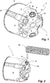
- a cavity wall socket 1 as an exemplary installation socket for receiving electrical / electronic installation devices, such as a socket, a device carrier, a switching device or the like, comprises a socket body 2.
- the socket body 2 is formed by a circumferential cylindrical wall 3 and a base 4 .
- the can body 2 has an in Figure 1 Assembly opening 5, which cannot be seen from the perspective, through which the desired installations can be introduced into the cavity wall box 1.
- a support flange 6 is formed on the can body 2, enclosing the assembly opening 5, in the radial direction outward.
- the can body 2, as described above, is made from a hard plastic, typically from a thermoplastic plastic. This also provides the necessary electrical insulation between the interior of the can body 2 and its outside.
- the bottom 4, which also includes the inclined section connecting the bottom 4 to the side wall 3, has several pipe entries made as openings in the can body 2 . These are in Figure 1 not recognizable as each covered by a soft plastic membrane. In Figure 1 only some of the several soft plastic membranes spanning a pipe entry are identified with the reference symbol 7. For manufacturing reasons, the soft plastic membranes 7 are connected to one another via sprue channels. The soft plastic and the soft plastic membrane 7 formed by it is an elastomeric soft plastic, as is known from installation boxes of the type in question.
- the cavity wall box 1 is manufactured as a two-component injection-molded part. In a first step, the can body 2 made of hard plastic has been originally formed. In a subsequent step, the soft plastic component has been molded onto the can body 2 in a suitable tool.
- those soft plastic membranes 7 are of interest which have an outwardly directed bead approximately in the area of the center of the tube entry in the can body 2 and a tear handle 9 in the area of the soft plastic membrane 7 enclosed by the bead 8.
- the expansion of the pipe entry spanned by the soft plastic membrane 7 in the can body 2 corresponds to FIG Figure 1 upper soft plastic membrane 7 carrying the tear handle 9 in approximately the extent shown in this figure.
- the area of the soft plastic membrane 7 enclosed by the bead 8 represents a tear area 10 which is separated from the soft plastic membrane 7 before an installation pipe, for example a corrugated hose, is inserted through the opening created.
- the tear handle 9 is used for the defined separation of the tear area 10 enclosed by the bead 8. In the exemplary embodiment shown, this is designed as a web that is molded onto the tear area 10 and protrudes therefrom.
- the visible upper side of the tear handle 9 is formed by an actuating surface 11.
- the tear handle 9 has a concave curvature with its actuating surface 11, this curvature being adapted to the radius of curvature of an installation pipe to be inserted through the soft plastic membrane 7.
- the tear handle 9 is supported on the underside by several support ribs 12 on the surface of the tear region 10.
- a tear contour 13 is provided which is provided by a material thinning compared to the material thickness of the remaining tear region 10 (see also FIG Figure 4 ).
- the material thickness in the area of the tear contour is approximately 0.5 mm in the illustrated embodiment. In the adjoining areas of the tear area 10, the material thickness is approximately 1.5 to 2 mm.
- the concave curvature of the tear handle 9 designed as a web is off-center with respect to the tear area 10 enclosed by the bead 8 (see FIG Figure 3 ).
- the tear handle 9 is offset off-center in that section of the tear area 10 into which the concave contour of the tear handle 9 points.
- the curvature of the tear handle 9 runs in the opposite direction to the curvature of the tear contour 13.
- the tear handle 9 extends up to the tear contour 13.
- the lateral ends of the tear handle 9 merge directly into the tear contour 13 formed by the thinning of the material.
- the angle ⁇ that the tear handle 9 encloses with the tear contour 13 in the area of its lateral ends is approximately 40 to 45 in the illustrated embodiment, in which the opening spanned by the tear area 10 is provided for inserting an installation pipe with a diameter of 20 mm Degree.
- the tool used is a corrugated hose 14 which, in this exemplary embodiment, represents the installation pipe to be inserted into the socket body 2 with its end section.
- the end section of the corrugated hose 14 is brought into contact with the actuation surface 11 of the tear handle 9, as shown in FIG Figure 2 is indicated by the block arrow.
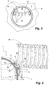
- the contact situation between the corrugated hose 14 and the tear handle 9 is from the sectional view of FIG Figure 3 recognizable, in which the end section of the corrugated hose 14 rests on the actuating surface 11 of the tear handle 9.
- Figure 3 allows the bead 8 protruding on the outside from the soft plastic membrane 7 to be clearly seen on the basis of the sectional illustration.
- This bulge is not only located on the outside of the soft plastic membrane 7, but also on the side facing the inside of the can.
- the inner bead is identified in this figure with the reference symbol 15.
- the tear contour 13, which is molded onto the radial inside of the bead formation, formed from the beads 8, 15, and is characterized by a thinning of the material compared to the material thickness of the tear area 10, can also be clearly seen in this sectional illustration.
- the corrugated hose 14 is pressed against the actuating surface 11 of the tear handle 9, as indicated by the block arrow in FIG Figure 3 indicated.
- the force acting on the tear handle 9 is introduced directly into the tear contour 13 via the latter due to its extension up to the tear contour 13 in the area of the lateral ends of the tear handle 9. In this way, a shear force is introduced into the tear contour 13 in the area of the lateral ends of the tear handle 9.
- the application of force to the tear handle 9 causes the in Figure 3 A tensile force acts above the tear handle 9 of the section 16 of the tear area 10. Since the soft plastic membrane 7 is elastic, it undergoes the greatest elongation at the point where the smallest material thickness is present, i.e.
- the material thinning of the tear contour 13 is designed so that, for a given, on the actuating surface 11, the tear handle 9 acting force tears the tear contour in a defined manner due to the shear and tensile forces introduced into it via the tear handle 9.
- the tensile force acts on the upper apex 17 of the tear contour, consequently that section of the tear contour 13 which lies opposite the apex of the concave curvature of the actuating surface 11.
- the tear process is supported by the compression resulting from the exertion of force and the shear occurring in the two opposite vertices. If the tear is circumferential to the tear area 10 or has at least propagated so far that the tear area 10 can be folded into the interior of the can body 2, the corrugated hose 14 can be pushed through the opening created through the soft plastic membrane 7 and thus through the tube entry of the can body 2 be passed through. This insertion is accompanied by a widening of the bulge embossing 8, 15 and the inversion of the areas of the soft plastic membrane 7 that adjoin the bulging embossing 8, 15 radially on the outside.
- the corrugated tube 14 inserted into the opening created in this way in the soft plastic membrane 7 is shown in FIG Figure 4 shown.
- the outer diameter of the corrugated hose 14 is approximately twice as large as the inner diameter of the bead formation 8, 15 in the non-deformed state in the illustrated embodiment. This means that the in Figure 4
- the position shown of the cavity wall socket 1 and the corrugated hose 14, the outside bead 8 engages in an outer groove 18 of the corrugated hose 14 in the manner of an O-ring while standing under pretension and is held locked therein.
- the areas of the soft plastic membrane 7 lying radially on the outside with respect to the bulge embossing 8, 15 also lie against the outside of the corrugated hose 14 under prestress.
- a sealing cuff is formed which ensures windproofness between the inside and outside of the can despite the corrugated hose 14 being inserted.
- Figure 5 shows, in a further position, a corrugated hose 14 which is initially pushed too deeply into the cavity wall socket 1 and which has already been pulled somewhat out of the cavity wall socket 1 or the socket body 2.
- the wall areas of the soft plastic membrane 7 that were initially turned inside when pushed in have turned out so that the inside of the areas of the soft plastic membrane 7 adjoining the bulge formation 8, 15 now lie against the outside of the corrugated hose 14.
- the inner bead 15 is locked in an outer groove 18 of the corrugated hose 14. Windproofness is also ensured in this position between the inside and outside of the can.
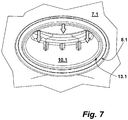
- Figure 7 shows in a plan view corresponding to that of FIG Figure 3 a section of a further soft plastic membrane 7.1 spanning a pipe entry, the tear area 10.1, in contrast to the embodiment described above, is elliptical.
- the tear handle 9.1 extends with its longitudinal extension transversely to the short axis of the elliptical tear area 10.1.
- the tear area 10.1 is bordered by a circumferential bead 8.1 which is pronounced on both sides and a tear contour 13.1 formed thereon on the inside.
- the comments on the embodiment of Figures 1 to 6 apply equally to the design of the tear area 10.1 Figure 7 .
- the diameter of the installation pipe is slightly larger than the long axis of the tear area 10.1.
- the short axis is significantly smaller than the diameter of an opening in the soft plastic membrane 7.1 created by removing the tear area 10.1. This simplifies the insertion of an installation pipe designed in particular as a corrugated pipe. After the tear area 10.1 has been removed, the opposing bulge walls jump into a corrugated valley of an installation pipe designed as a corrugated pipe and ensure the necessary retention function.
Landscapes
- Engineering & Computer Science (AREA)
- Architecture (AREA)
- Civil Engineering (AREA)
- Structural Engineering (AREA)
- Rigid Pipes And Flexible Pipes (AREA)
- Laying Of Electric Cables Or Lines Outside (AREA)
Priority Applications (1)
| Application Number | Priority Date | Filing Date | Title |
|---|---|---|---|
| PL20158372T PL3703206T3 (pl) | 2019-02-27 | 2020-02-20 | Puszka instalacyjna oraz jednostka instalacyjna z taką puszką instalacyjną i rurą instalacyjną |
Applications Claiming Priority (1)
| Application Number | Priority Date | Filing Date | Title |
|---|---|---|---|
| DE202019101118.1U DE202019101118U1 (de) | 2019-02-27 | 2019-02-27 | Installationsdose sowie Installationseinheit mit einer solchen Installationsdose und mit einem Installationsrohr |
Publications (2)
| Publication Number | Publication Date |
|---|---|
| EP3703206A1 true EP3703206A1 (fr) | 2020-09-02 |
| EP3703206B1 EP3703206B1 (fr) | 2021-06-30 |
Family
ID=69713943
Family Applications (1)
| Application Number | Title | Priority Date | Filing Date |
|---|---|---|---|
| EP20158372.1A Active EP3703206B1 (fr) | 2019-02-27 | 2020-02-20 | Boîte d'installation ainsi qu'unité d'installation dotée d'une telle boîte d'installation et d'un tuyau d'installation |
Country Status (6)
| Country | Link |
|---|---|
| EP (1) | EP3703206B1 (fr) |
| DE (1) | DE202019101118U1 (fr) |
| ES (1) | ES2881879T3 (fr) |
| HU (1) | HUE055082T2 (fr) |
| PL (1) | PL3703206T3 (fr) |
| PT (1) | PT3703206T (fr) |
Cited By (2)
| Publication number | Priority date | Publication date | Assignee | Title |
|---|---|---|---|---|
| EP3790136A1 (fr) * | 2019-09-06 | 2021-03-10 | Kaiser GmbH & Co. KG | Boite d'installation |
| EP4277062A1 (fr) * | 2022-05-12 | 2023-11-15 | HSB Weibel AG | Boîtier à paroi creuse à fixation simplifiée du tube de protection des câbles |
Citations (2)
| Publication number | Priority date | Publication date | Assignee | Title |
|---|---|---|---|---|
| FR3011139A1 (fr) * | 2013-09-25 | 2015-03-27 | Legrand France | Boite electrique d'encastrement |
| EP3540885A1 (fr) * | 2018-03-14 | 2019-09-18 | Kaiser GmbH & Co. KG | Boîte d'installation |
Family Cites Families (1)
| Publication number | Priority date | Publication date | Assignee | Title |
|---|---|---|---|---|
| DE202010004188U1 (de) * | 2010-02-12 | 2011-08-08 | Kaiser Gmbh & Co. Kommanditgesellschaft | Installationsteil |
-
2019
- 2019-02-27 DE DE202019101118.1U patent/DE202019101118U1/de active Active
-
2020
- 2020-02-20 ES ES20158372T patent/ES2881879T3/es active Active
- 2020-02-20 PL PL20158372T patent/PL3703206T3/pl unknown
- 2020-02-20 EP EP20158372.1A patent/EP3703206B1/fr active Active
- 2020-02-20 HU HUE20158372A patent/HUE055082T2/hu unknown
- 2020-02-20 PT PT201583721T patent/PT3703206T/pt unknown
Patent Citations (2)
| Publication number | Priority date | Publication date | Assignee | Title |
|---|---|---|---|---|
| FR3011139A1 (fr) * | 2013-09-25 | 2015-03-27 | Legrand France | Boite electrique d'encastrement |
| EP3540885A1 (fr) * | 2018-03-14 | 2019-09-18 | Kaiser GmbH & Co. KG | Boîte d'installation |
Non-Patent Citations (1)
| Title |
|---|
| ANNONYMOUS: "NOUVEAU BOÎTES D'ENCASTREMENT ÉTANCHES À L'AIR POUR CLOISONS CREUSES", 20 October 2017 (2017-10-20), XP055696198, Retrieved from the Internet <URL:https://www.bticino.be/sites/default/files/brochures/brochure_luchtdichte_inbouwdozen_holle_wanden_FR_v2.pdf> [retrieved on 20200518] * |
Cited By (2)
| Publication number | Priority date | Publication date | Assignee | Title |
|---|---|---|---|---|
| EP3790136A1 (fr) * | 2019-09-06 | 2021-03-10 | Kaiser GmbH & Co. KG | Boite d'installation |
| EP4277062A1 (fr) * | 2022-05-12 | 2023-11-15 | HSB Weibel AG | Boîtier à paroi creuse à fixation simplifiée du tube de protection des câbles |
Also Published As
| Publication number | Publication date |
|---|---|
| PT3703206T (pt) | 2021-08-17 |
| HUE055082T2 (hu) | 2021-10-28 |
| PL3703206T3 (pl) | 2021-11-22 |
| DE202019101118U1 (de) | 2020-05-28 |
| EP3703206B1 (fr) | 2021-06-30 |
| ES2881879T3 (es) | 2021-11-30 |
Similar Documents
| Publication | Publication Date | Title |
|---|---|---|
| EP3540885B1 (fr) | Boîte d'installation | |
| EP2360800B1 (fr) | Elément d'installation | |
| DE2909538A1 (de) | Rohrteil mit einem muffenende sowie verfahren und vorrichtung zu seiner herstellung | |
| EP1843071A1 (fr) | Bourrage d'étanchéité pour l'utilisation dans un mur | |
| EP3026766B1 (fr) | Introduction de tube pour une boite de branchement | |
| EP3703206B1 (fr) | Boîte d'installation ainsi qu'unité d'installation dotée d'une telle boîte d'installation et d'un tuyau d'installation | |
| DE202009003184U1 (de) | Dichtungsvorrichtung zum Abdichten eines Durchbruchs | |
| EP4239817A1 (fr) | Entrée de câble | |
| EP3731358B1 (fr) | Prise d'installation et agencement de prise d'installation doté d'une telle prise d'installation | |
| DE69107482T2 (de) | Lötfreier elektrischer steckverbinder. | |
| WO2011124495A2 (fr) | Pince de retenue | |
| EP1737094B1 (fr) | Manchon pour une retenue sécurisée lors de l'entrée d'un tube ondulé | |
| EP3886278B1 (fr) | Boîte d'installation | |
| DE102016121586B3 (de) | Anordnung mit einer Elektroinstallationsdose und einem mit der Elektroinstallationsdose verbindbaren Rohradapter | |
| CH711118A1 (de) | Rohrmuffe für Well- und Glattrohre. | |
| EP1719942A2 (fr) | Manchon de tuyau pour conduites de câbles | |
| AT522412B1 (de) | Installationsdose und Installationsdosenanordnung mit einer solchen Installationsdose | |
| EP4047764A1 (fr) | Boîte d'installation | |
| DE2937228C2 (de) | Dichtnippel | |
| WO2022223429A1 (fr) | Composant de chemin de câbles constitué de métal, plus particulièrement chemin de câbles ou couvercle de chemin de câbles | |
| EP1544380A2 (fr) | Tube d'écartement pour le guidage de barres de tension | |
| EP1930639B1 (fr) | Joint d'étanchéité compressible | |
| DE10125625A1 (de) | Dichtungstülle insbesondere für einen Kabelübergangskasten | |
| DE10313304B3 (de) | Rohrelement mit Abtrennmitteln | |
| DE102021110003B3 (de) | Installationsdose mit einer Installationsöffnung zum Einführen eines Leerrohres oder Kabels |
Legal Events
| Date | Code | Title | Description |
|---|---|---|---|
| PUAI | Public reference made under article 153(3) epc to a published international application that has entered the european phase |
Free format text: ORIGINAL CODE: 0009012 |
|
| STAA | Information on the status of an ep patent application or granted ep patent |
Free format text: STATUS: REQUEST FOR EXAMINATION WAS MADE |
|
| STAA | Information on the status of an ep patent application or granted ep patent |
Free format text: STATUS: EXAMINATION IS IN PROGRESS |
|
| 17P | Request for examination filed |
Effective date: 20200622 |
|
| AK | Designated contracting states |
Kind code of ref document: A1 Designated state(s): AL AT BE BG CH CY CZ DE DK EE ES FI FR GB GR HR HU IE IS IT LI LT LU LV MC MK MT NL NO PL PT RO RS SE SI SK SM TR |
|
| AX | Request for extension of the european patent |
Extension state: BA ME |
|
| 17Q | First examination report despatched |
Effective date: 20200901 |
|
| 17Q | First examination report despatched |
Effective date: 20200915 |
|
| RBV | Designated contracting states (corrected) |
Designated state(s): AL AT BE BG CH CY CZ DE DK EE ES FI FR GB GR HR HU IE IS IT LI LT LU LV MC MK MT NL NO PL PT RO RS SE SI SK SM TR |
|
| GRAP | Despatch of communication of intention to grant a patent |
Free format text: ORIGINAL CODE: EPIDOSNIGR1 |
|
| STAA | Information on the status of an ep patent application or granted ep patent |
Free format text: STATUS: GRANT OF PATENT IS INTENDED |
|
| RIC1 | Information provided on ipc code assigned before grant |
Ipc: H02G 3/06 20060101ALI20210218BHEP Ipc: H02G 3/12 20060101ALI20210218BHEP Ipc: H02G 3/08 20060101AFI20210218BHEP Ipc: H02G 3/04 20060101ALN20210218BHEP |
|
| RIC1 | Information provided on ipc code assigned before grant |
Ipc: H02G 3/06 20060101ALI20210222BHEP Ipc: H02G 3/04 20060101ALN20210222BHEP Ipc: H02G 3/08 20060101AFI20210222BHEP Ipc: H02G 3/12 20060101ALI20210222BHEP |
|
| RIC1 | Information provided on ipc code assigned before grant |
Ipc: H02G 3/06 20060101ALI20210301BHEP Ipc: H02G 3/12 20060101ALI20210301BHEP Ipc: H02G 3/08 20060101AFI20210301BHEP Ipc: H02G 3/04 20060101ALN20210301BHEP |
|
| RIC1 | Information provided on ipc code assigned before grant |
Ipc: H02G 3/08 20060101AFI20210308BHEP Ipc: H02G 3/12 20060101ALI20210308BHEP Ipc: H02G 3/06 20060101ALI20210308BHEP Ipc: H02G 3/04 20060101ALN20210308BHEP |
|
| INTG | Intention to grant announced |
Effective date: 20210322 |
|
| RIN1 | Information on inventor provided before grant (corrected) |
Inventor name: HARMS, HEIKO Inventor name: KOLERT, SERGEJ |
|
| GRAS | Grant fee paid |
Free format text: ORIGINAL CODE: EPIDOSNIGR3 |
|
| GRAA | (expected) grant |
Free format text: ORIGINAL CODE: 0009210 |
|
| STAA | Information on the status of an ep patent application or granted ep patent |
Free format text: STATUS: THE PATENT HAS BEEN GRANTED |
|
| AK | Designated contracting states |
Kind code of ref document: B1 Designated state(s): AL AT BE BG CH CY CZ DE DK EE ES FI FR GB GR HR HU IE IS IT LI LT LU LV MC MK MT NL NO PL PT RO RS SE SI SK SM TR |
|
| REG | Reference to a national code |
Ref country code: CH Ref legal event code: EP |
|
| REG | Reference to a national code |
Ref country code: AT Ref legal event code: REF Ref document number: 1407234 Country of ref document: AT Kind code of ref document: T Effective date: 20210715 |
|
| REG | Reference to a national code |
Ref country code: DE Ref legal event code: R096 Ref document number: 502020000072 Country of ref document: DE |
|
| REG | Reference to a national code |
Ref country code: IE Ref legal event code: FG4D Free format text: LANGUAGE OF EP DOCUMENT: GERMAN Ref country code: NL Ref legal event code: FP |
|
| REG | Reference to a national code |
Ref country code: PT Ref legal event code: SC4A Ref document number: 3703206 Country of ref document: PT Date of ref document: 20210817 Kind code of ref document: T Free format text: AVAILABILITY OF NATIONAL TRANSLATION Effective date: 20210805 Ref country code: SE Ref legal event code: TRGR |
|
| REG | Reference to a national code |
Ref country code: NO Ref legal event code: T2 Effective date: 20210630 Ref country code: LT Ref legal event code: MG9D |
|
| REG | Reference to a national code |
Ref country code: HU Ref legal event code: AG4A Ref document number: E055082 Country of ref document: HU |
|
| PG25 | Lapsed in a contracting state [announced via postgrant information from national office to epo] |
Ref country code: HR Free format text: LAPSE BECAUSE OF FAILURE TO SUBMIT A TRANSLATION OF THE DESCRIPTION OR TO PAY THE FEE WITHIN THE PRESCRIBED TIME-LIMIT Effective date: 20210630 Ref country code: FI Free format text: LAPSE BECAUSE OF FAILURE TO SUBMIT A TRANSLATION OF THE DESCRIPTION OR TO PAY THE FEE WITHIN THE PRESCRIBED TIME-LIMIT Effective date: 20210630 Ref country code: BG Free format text: LAPSE BECAUSE OF FAILURE TO SUBMIT A TRANSLATION OF THE DESCRIPTION OR TO PAY THE FEE WITHIN THE PRESCRIBED TIME-LIMIT Effective date: 20210930 |
|
| PG25 | Lapsed in a contracting state [announced via postgrant information from national office to epo] |
Ref country code: RS Free format text: LAPSE BECAUSE OF FAILURE TO SUBMIT A TRANSLATION OF THE DESCRIPTION OR TO PAY THE FEE WITHIN THE PRESCRIBED TIME-LIMIT Effective date: 20210630 Ref country code: LV Free format text: LAPSE BECAUSE OF FAILURE TO SUBMIT A TRANSLATION OF THE DESCRIPTION OR TO PAY THE FEE WITHIN THE PRESCRIBED TIME-LIMIT Effective date: 20210630 Ref country code: GR Free format text: LAPSE BECAUSE OF FAILURE TO SUBMIT A TRANSLATION OF THE DESCRIPTION OR TO PAY THE FEE WITHIN THE PRESCRIBED TIME-LIMIT Effective date: 20211001 |
|
| REG | Reference to a national code |
Ref country code: ES Ref legal event code: FG2A Ref document number: 2881879 Country of ref document: ES Kind code of ref document: T3 Effective date: 20211130 |
|
| REG | Reference to a national code |
Ref country code: DE Ref legal event code: R082 Ref document number: 502020000072 Country of ref document: DE Representative=s name: HAVERKAMP PATENTANWAELTE PARTG MBB, DE |
|
| PG25 | Lapsed in a contracting state [announced via postgrant information from national office to epo] |
Ref country code: EE Free format text: LAPSE BECAUSE OF FAILURE TO SUBMIT A TRANSLATION OF THE DESCRIPTION OR TO PAY THE FEE WITHIN THE PRESCRIBED TIME-LIMIT Effective date: 20210630 Ref country code: SK Free format text: LAPSE BECAUSE OF FAILURE TO SUBMIT A TRANSLATION OF THE DESCRIPTION OR TO PAY THE FEE WITHIN THE PRESCRIBED TIME-LIMIT Effective date: 20210630 Ref country code: SM Free format text: LAPSE BECAUSE OF FAILURE TO SUBMIT A TRANSLATION OF THE DESCRIPTION OR TO PAY THE FEE WITHIN THE PRESCRIBED TIME-LIMIT Effective date: 20210630 Ref country code: RO Free format text: LAPSE BECAUSE OF FAILURE TO SUBMIT A TRANSLATION OF THE DESCRIPTION OR TO PAY THE FEE WITHIN THE PRESCRIBED TIME-LIMIT Effective date: 20210630 |
|
| REG | Reference to a national code |
Ref country code: DE Ref legal event code: R097 Ref document number: 502020000072 Country of ref document: DE |
|
| PG25 | Lapsed in a contracting state [announced via postgrant information from national office to epo] |
Ref country code: DK Free format text: LAPSE BECAUSE OF FAILURE TO SUBMIT A TRANSLATION OF THE DESCRIPTION OR TO PAY THE FEE WITHIN THE PRESCRIBED TIME-LIMIT Effective date: 20210630 |
|
| PLBE | No opposition filed within time limit |
Free format text: ORIGINAL CODE: 0009261 |
|
| STAA | Information on the status of an ep patent application or granted ep patent |
Free format text: STATUS: NO OPPOSITION FILED WITHIN TIME LIMIT |
|
| PG25 | Lapsed in a contracting state [announced via postgrant information from national office to epo] |
Ref country code: AL Free format text: LAPSE BECAUSE OF FAILURE TO SUBMIT A TRANSLATION OF THE DESCRIPTION OR TO PAY THE FEE WITHIN THE PRESCRIBED TIME-LIMIT Effective date: 20210630 |
|
| 26N | No opposition filed |
Effective date: 20220331 |
|
| PG25 | Lapsed in a contracting state [announced via postgrant information from national office to epo] |
Ref country code: MC Free format text: LAPSE BECAUSE OF FAILURE TO SUBMIT A TRANSLATION OF THE DESCRIPTION OR TO PAY THE FEE WITHIN THE PRESCRIBED TIME-LIMIT Effective date: 20210630 |
|
| PG25 | Lapsed in a contracting state [announced via postgrant information from national office to epo] |
Ref country code: LU Free format text: LAPSE BECAUSE OF NON-PAYMENT OF DUE FEES Effective date: 20220220 |
|
| PG25 | Lapsed in a contracting state [announced via postgrant information from national office to epo] |
Ref country code: IE Free format text: LAPSE BECAUSE OF NON-PAYMENT OF DUE FEES Effective date: 20220220 |
|
| PG25 | Lapsed in a contracting state [announced via postgrant information from national office to epo] |
Ref country code: LT Free format text: LAPSE BECAUSE OF FAILURE TO SUBMIT A TRANSLATION OF THE DESCRIPTION OR TO PAY THE FEE WITHIN THE PRESCRIBED TIME-LIMIT Effective date: 20210630 |
|
| P01 | Opt-out of the competence of the unified patent court (upc) registered |
Effective date: 20230529 |
|
| REG | Reference to a national code |
Ref country code: CH Ref legal event code: PL |
|
| PG25 | Lapsed in a contracting state [announced via postgrant information from national office to epo] |
Ref country code: LI Free format text: LAPSE BECAUSE OF NON-PAYMENT OF DUE FEES Effective date: 20230228 Ref country code: CH Free format text: LAPSE BECAUSE OF NON-PAYMENT OF DUE FEES Effective date: 20230228 |
|
| PG25 | Lapsed in a contracting state [announced via postgrant information from national office to epo] |
Ref country code: MK Free format text: LAPSE BECAUSE OF FAILURE TO SUBMIT A TRANSLATION OF THE DESCRIPTION OR TO PAY THE FEE WITHIN THE PRESCRIBED TIME-LIMIT Effective date: 20210630 Ref country code: CY Free format text: LAPSE BECAUSE OF FAILURE TO SUBMIT A TRANSLATION OF THE DESCRIPTION OR TO PAY THE FEE WITHIN THE PRESCRIBED TIME-LIMIT Effective date: 20210630 |
|
| PG25 | Lapsed in a contracting state [announced via postgrant information from national office to epo] |
Ref country code: TR Free format text: LAPSE BECAUSE OF FAILURE TO SUBMIT A TRANSLATION OF THE DESCRIPTION OR TO PAY THE FEE WITHIN THE PRESCRIBED TIME-LIMIT Effective date: 20210630 |
|
| PG25 | Lapsed in a contracting state [announced via postgrant information from national office to epo] |
Ref country code: MT Free format text: LAPSE BECAUSE OF FAILURE TO SUBMIT A TRANSLATION OF THE DESCRIPTION OR TO PAY THE FEE WITHIN THE PRESCRIBED TIME-LIMIT Effective date: 20210630 |
|
| GBPC | Gb: european patent ceased through non-payment of renewal fee |
Effective date: 20240220 |
|
| PG25 | Lapsed in a contracting state [announced via postgrant information from national office to epo] |
Ref country code: GB Free format text: LAPSE BECAUSE OF NON-PAYMENT OF DUE FEES Effective date: 20240220 |
|
| PG25 | Lapsed in a contracting state [announced via postgrant information from national office to epo] |
Ref country code: GB Free format text: LAPSE BECAUSE OF NON-PAYMENT OF DUE FEES Effective date: 20240220 |
|
| PGFP | Annual fee paid to national office [announced via postgrant information from national office to epo] |
Ref country code: NL Payment date: 20250220 Year of fee payment: 6 |
|
| PGFP | Annual fee paid to national office [announced via postgrant information from national office to epo] |
Ref country code: ES Payment date: 20250318 Year of fee payment: 6 |
|
| PGFP | Annual fee paid to national office [announced via postgrant information from national office to epo] |
Ref country code: SE Payment date: 20250219 Year of fee payment: 6 |
|
| PGFP | Annual fee paid to national office [announced via postgrant information from national office to epo] |
Ref country code: NO Payment date: 20250218 Year of fee payment: 6 |
|
| PGFP | Annual fee paid to national office [announced via postgrant information from national office to epo] |
Ref country code: BE Payment date: 20250218 Year of fee payment: 6 |
|
| PGFP | Annual fee paid to national office [announced via postgrant information from national office to epo] |
Ref country code: FR Payment date: 20250219 Year of fee payment: 6 |
|
| PGFP | Annual fee paid to national office [announced via postgrant information from national office to epo] |
Ref country code: IT Payment date: 20250228 Year of fee payment: 6 |
|
| PGFP | Annual fee paid to national office [announced via postgrant information from national office to epo] |
Ref country code: HU Payment date: 20260213 Year of fee payment: 7 |
|
| PGFP | Annual fee paid to national office [announced via postgrant information from national office to epo] |
Ref country code: DE Payment date: 20260128 Year of fee payment: 7 |
|
| PGFP | Annual fee paid to national office [announced via postgrant information from national office to epo] |
Ref country code: AT Payment date: 20260128 Year of fee payment: 7 |
|
| PGFP | Annual fee paid to national office [announced via postgrant information from national office to epo] |
Ref country code: PT Payment date: 20260206 Year of fee payment: 7 Ref country code: CZ Payment date: 20260206 Year of fee payment: 7 |
|
| PGFP | Annual fee paid to national office [announced via postgrant information from national office to epo] |
Ref country code: PL Payment date: 20260205 Year of fee payment: 7 |