EP3703242B1 - Schaltvorrichtung für einen ein- oder mehrphasigen elektrischen verbraucher - Google Patents
Schaltvorrichtung für einen ein- oder mehrphasigen elektrischen verbraucher Download PDFInfo
- Publication number
- EP3703242B1 EP3703242B1 EP19160214.3A EP19160214A EP3703242B1 EP 3703242 B1 EP3703242 B1 EP 3703242B1 EP 19160214 A EP19160214 A EP 19160214A EP 3703242 B1 EP3703242 B1 EP 3703242B1
- Authority
- EP
- European Patent Office
- Prior art keywords
- phase
- switching device
- connection
- power module
- connection part
- Prior art date
- Legal status (The legal status is an assumption and is not a legal conclusion. Google has not performed a legal analysis and makes no representation as to the accuracy of the status listed.)
- Active
Links
Images



Classifications
-
- H—ELECTRICITY
- H02—GENERATION; CONVERSION OR DISTRIBUTION OF ELECTRIC POWER
- H02M—APPARATUS FOR CONVERSION BETWEEN AC AND AC, BETWEEN AC AND DC, OR BETWEEN DC AND DC, AND FOR USE WITH MAINS OR SIMILAR POWER SUPPLY SYSTEMS; CONVERSION OF DC OR AC INPUT POWER INTO SURGE OUTPUT POWER; CONTROL OR REGULATION THEREOF
- H02M5/00—Conversion of AC power input into AC power output, e.g. for change of voltage, for change of frequency, for change of number of phases
- H02M5/02—Conversion of AC power input into AC power output, e.g. for change of voltage, for change of frequency, for change of number of phases without intermediate conversion into DC
- H02M5/04—Conversion of AC power input into AC power output, e.g. for change of voltage, for change of frequency, for change of number of phases without intermediate conversion into DC by static converters
- H02M5/22—Conversion of AC power input into AC power output, e.g. for change of voltage, for change of frequency, for change of number of phases without intermediate conversion into DC by static converters using discharge tubes with control electrode or semiconductor devices with control electrode
- H02M5/25—Conversion of AC power input into AC power output, e.g. for change of voltage, for change of frequency, for change of number of phases without intermediate conversion into DC by static converters using discharge tubes with control electrode or semiconductor devices with control electrode using devices of a thyratron or thyristor type requiring extinguishing means
- H02M5/257—Conversion of AC power input into AC power output, e.g. for change of voltage, for change of frequency, for change of number of phases without intermediate conversion into DC by static converters using discharge tubes with control electrode or semiconductor devices with control electrode using devices of a thyratron or thyristor type requiring extinguishing means using semiconductor devices only
-
- H—ELECTRICITY
- H02—GENERATION; CONVERSION OR DISTRIBUTION OF ELECTRIC POWER
- H02M—APPARATUS FOR CONVERSION BETWEEN AC AND AC, BETWEEN AC AND DC, OR BETWEEN DC AND DC, AND FOR USE WITH MAINS OR SIMILAR POWER SUPPLY SYSTEMS; CONVERSION OF DC OR AC INPUT POWER INTO SURGE OUTPUT POWER; CONTROL OR REGULATION THEREOF
- H02M1/00—Details of apparatus for conversion
-
- H—ELECTRICITY
- H01—ELECTRIC ELEMENTS
- H01H—ELECTRIC SWITCHES; RELAYS; SELECTORS; EMERGENCY PROTECTIVE DEVICES
- H01H1/00—Contacts
- H01H1/58—Electric connections to or between contacts; Terminals
-
- H—ELECTRICITY
- H01—ELECTRIC ELEMENTS
- H01H—ELECTRIC SWITCHES; RELAYS; SELECTORS; EMERGENCY PROTECTIVE DEVICES
- H01H71/00—Details of the protective switches or relays covered by groups H01H73/00 - H01H83/00
- H01H71/10—Operating or release mechanisms
- H01H71/12—Automatic release mechanisms with or without manual release
- H01H71/123—Automatic release mechanisms with or without manual release using a solid-state trip unit
- H01H71/125—Automatic release mechanisms with or without manual release using a solid-state trip unit characterised by sensing elements, e.g. current transformers
-
- H—ELECTRICITY
- H01—ELECTRIC ELEMENTS
- H01H—ELECTRIC SWITCHES; RELAYS; SELECTORS; EMERGENCY PROTECTIVE DEVICES
- H01H9/00—Details of switching devices, not covered by groups H01H1/00 - H01H7/00
- H01H9/54—Circuit arrangements not adapted to a particular application of the switching device and for which no provision exists elsewhere
- H01H9/541—Contacts shunted by semiconductor devices
-
- H—ELECTRICITY
- H02—GENERATION; CONVERSION OR DISTRIBUTION OF ELECTRIC POWER
- H02P—CONTROL OR REGULATION OF ELECTRIC MOTORS, ELECTRIC GENERATORS OR DYNAMO-ELECTRIC CONVERTERS; CONTROLLING TRANSFORMERS, REACTORS OR CHOKE COILS
- H02P1/00—Arrangements for starting electric motors or dynamo-electric converters
- H02P1/02—Details of starting control
-
- H—ELECTRICITY
- H02—GENERATION; CONVERSION OR DISTRIBUTION OF ELECTRIC POWER
- H02P—CONTROL OR REGULATION OF ELECTRIC MOTORS, ELECTRIC GENERATORS OR DYNAMO-ELECTRIC CONVERTERS; CONTROLLING TRANSFORMERS, REACTORS OR CHOKE COILS
- H02P1/00—Arrangements for starting electric motors or dynamo-electric converters
- H02P1/16—Arrangements for starting electric motors or dynamo-electric converters for starting dynamo-electric motors or dynamo-electric converters
-
- H—ELECTRICITY
- H03—ELECTRONIC CIRCUITRY
- H03K—PULSE TECHNIQUE
- H03K17/00—Electronic switching or gating, i.e. not by contact-making and –breaking
- H03K17/16—Modifications for eliminating interference voltages or currents
- H03K17/161—Modifications for eliminating interference voltages or currents in field-effect transistor switches
- H03K17/165—Modifications for eliminating interference voltages or currents in field-effect transistor switches by feedback from the output circuit to the control circuit
- H03K17/166—Soft switching
-
- H—ELECTRICITY
- H05—ELECTRIC TECHNIQUES NOT OTHERWISE PROVIDED FOR
- H05K—PRINTED CIRCUITS; CASINGS OR CONSTRUCTIONAL DETAILS OF ELECTRIC APPARATUS; MANUFACTURE OF ASSEMBLAGES OF ELECTRICAL COMPONENTS
- H05K7/00—Constructional details common to different types of electric apparatus
- H05K7/02—Arrangements of circuit components or wiring on supporting structure
- H05K7/06—Arrangements of circuit components or wiring on supporting structure on insulating boards, e.g. wiring harnesses
-
- H—ELECTRICITY
- H05—ELECTRIC TECHNIQUES NOT OTHERWISE PROVIDED FOR
- H05K—PRINTED CIRCUITS; CASINGS OR CONSTRUCTIONAL DETAILS OF ELECTRIC APPARATUS; MANUFACTURE OF ASSEMBLAGES OF ELECTRICAL COMPONENTS
- H05K7/00—Constructional details common to different types of electric apparatus
- H05K7/14—Mounting supporting structure in casing or on frame or rack
- H05K7/1422—Printed circuit boards receptacles, e.g. stacked structures, electronic circuit modules or box like frames
- H05K7/1427—Housings
- H05K7/1432—Housings specially adapted for power drive units or power converters
- H05K7/14329—Housings specially adapted for power drive units or power converters specially adapted for the configuration of power bus bars
-
- H—ELECTRICITY
- H05—ELECTRIC TECHNIQUES NOT OTHERWISE PROVIDED FOR
- H05K—PRINTED CIRCUITS; CASINGS OR CONSTRUCTIONAL DETAILS OF ELECTRIC APPARATUS; MANUFACTURE OF ASSEMBLAGES OF ELECTRICAL COMPONENTS
- H05K7/00—Constructional details common to different types of electric apparatus
- H05K7/20—Modifications to facilitate cooling, ventilating, or heating
- H05K7/20009—Modifications to facilitate cooling, ventilating, or heating using a gaseous coolant in electronic enclosures
- H05K7/20136—Forced ventilation, e.g. by fans
-
- H—ELECTRICITY
- H05—ELECTRIC TECHNIQUES NOT OTHERWISE PROVIDED FOR
- H05K—PRINTED CIRCUITS; CASINGS OR CONSTRUCTIONAL DETAILS OF ELECTRIC APPARATUS; MANUFACTURE OF ASSEMBLAGES OF ELECTRICAL COMPONENTS
- H05K7/00—Constructional details common to different types of electric apparatus
- H05K7/20—Modifications to facilitate cooling, ventilating, or heating
- H05K7/2039—Modifications to facilitate cooling, ventilating, or heating characterised by the heat transfer by conduction from the heat generating element to a dissipating body
-
- H—ELECTRICITY
- H05—ELECTRIC TECHNIQUES NOT OTHERWISE PROVIDED FOR
- H05K—PRINTED CIRCUITS; CASINGS OR CONSTRUCTIONAL DETAILS OF ELECTRIC APPARATUS; MANUFACTURE OF ASSEMBLAGES OF ELECTRICAL COMPONENTS
- H05K7/00—Constructional details common to different types of electric apparatus
- H05K7/20—Modifications to facilitate cooling, ventilating, or heating
- H05K7/2089—Modifications to facilitate cooling, ventilating, or heating for power electronics, e.g. for inverters for controlling motor
- H05K7/209—Heat transfer by conduction from internal heat source to heat radiating structure
-
- H—ELECTRICITY
- H05—ELECTRIC TECHNIQUES NOT OTHERWISE PROVIDED FOR
- H05K—PRINTED CIRCUITS; CASINGS OR CONSTRUCTIONAL DETAILS OF ELECTRIC APPARATUS; MANUFACTURE OF ASSEMBLAGES OF ELECTRICAL COMPONENTS
- H05K7/00—Constructional details common to different types of electric apparatus
- H05K7/20—Modifications to facilitate cooling, ventilating, or heating
- H05K7/2089—Modifications to facilitate cooling, ventilating, or heating for power electronics, e.g. for inverters for controlling motor
- H05K7/20909—Forced ventilation, e.g. on heat dissipaters coupled to components
-
- H—ELECTRICITY
- H05—ELECTRIC TECHNIQUES NOT OTHERWISE PROVIDED FOR
- H05K—PRINTED CIRCUITS; CASINGS OR CONSTRUCTIONAL DETAILS OF ELECTRIC APPARATUS; MANUFACTURE OF ASSEMBLAGES OF ELECTRICAL COMPONENTS
- H05K7/00—Constructional details common to different types of electric apparatus
- H05K7/20—Modifications to facilitate cooling, ventilating, or heating
- H05K7/2089—Modifications to facilitate cooling, ventilating, or heating for power electronics, e.g. for inverters for controlling motor
- H05K7/20909—Forced ventilation, e.g. on heat dissipaters coupled to components
- H05K7/20918—Forced ventilation, e.g. on heat dissipaters coupled to components the components being isolated from air flow, e.g. hollow heat sinks, wind tunnels or funnels
-
- H—ELECTRICITY
- H10—SEMICONDUCTOR DEVICES; ELECTRIC SOLID-STATE DEVICES NOT OTHERWISE PROVIDED FOR
- H10W—GENERIC PACKAGES, INTERCONNECTIONS, CONNECTORS OR OTHER CONSTRUCTIONAL DETAILS OF DEVICES COVERED BY CLASS H10
- H10W40/00—Arrangements for thermal protection or thermal control
- H10W40/20—Arrangements for cooling
- H10W40/22—Arrangements for cooling characterised by their shape, e.g. having conical or cylindrical projections
-
- H—ELECTRICITY
- H10—SEMICONDUCTOR DEVICES; ELECTRIC SOLID-STATE DEVICES NOT OTHERWISE PROVIDED FOR
- H10W—GENERIC PACKAGES, INTERCONNECTIONS, CONNECTORS OR OTHER CONSTRUCTIONAL DETAILS OF DEVICES COVERED BY CLASS H10
- H10W40/00—Arrangements for thermal protection or thermal control
- H10W40/40—Arrangements for thermal protection or thermal control involving heat exchange by flowing fluids
- H10W40/43—Arrangements for thermal protection or thermal control involving heat exchange by flowing fluids by flowing gases, e.g. forced air cooling
-
- H—ELECTRICITY
- H10—SEMICONDUCTOR DEVICES; ELECTRIC SOLID-STATE DEVICES NOT OTHERWISE PROVIDED FOR
- H10W—GENERIC PACKAGES, INTERCONNECTIONS, CONNECTORS OR OTHER CONSTRUCTIONAL DETAILS OF DEVICES COVERED BY CLASS H10
- H10W40/00—Arrangements for thermal protection or thermal control
- H10W40/60—Securing means for detachable heating or cooling arrangements, e.g. clamps
- H10W40/611—Bolts or screws
-
- H—ELECTRICITY
- H02—GENERATION; CONVERSION OR DISTRIBUTION OF ELECTRIC POWER
- H02M—APPARATUS FOR CONVERSION BETWEEN AC AND AC, BETWEEN AC AND DC, OR BETWEEN DC AND DC, AND FOR USE WITH MAINS OR SIMILAR POWER SUPPLY SYSTEMS; CONVERSION OF DC OR AC INPUT POWER INTO SURGE OUTPUT POWER; CONTROL OR REGULATION THEREOF
- H02M1/00—Details of apparatus for conversion
- H02M1/0048—Circuits or arrangements for reducing losses
-
- H—ELECTRICITY
- H02—GENERATION; CONVERSION OR DISTRIBUTION OF ELECTRIC POWER
- H02M—APPARATUS FOR CONVERSION BETWEEN AC AND AC, BETWEEN AC AND DC, OR BETWEEN DC AND DC, AND FOR USE WITH MAINS OR SIMILAR POWER SUPPLY SYSTEMS; CONVERSION OF DC OR AC INPUT POWER INTO SURGE OUTPUT POWER; CONTROL OR REGULATION THEREOF
- H02M1/00—Details of apparatus for conversion
- H02M1/32—Means for protecting converters other than automatic disconnection
- H02M1/327—Means for protecting converters other than automatic disconnection against abnormal temperatures
-
- H—ELECTRICITY
- H02—GENERATION; CONVERSION OR DISTRIBUTION OF ELECTRIC POWER
- H02M—APPARATUS FOR CONVERSION BETWEEN AC AND AC, BETWEEN AC AND DC, OR BETWEEN DC AND DC, AND FOR USE WITH MAINS OR SIMILAR POWER SUPPLY SYSTEMS; CONVERSION OF DC OR AC INPUT POWER INTO SURGE OUTPUT POWER; CONTROL OR REGULATION THEREOF
- H02M1/00—Details of apparatus for conversion
- H02M1/36—Means for starting or stopping converters
-
- H—ELECTRICITY
- H02—GENERATION; CONVERSION OR DISTRIBUTION OF ELECTRIC POWER
- H02M—APPARATUS FOR CONVERSION BETWEEN AC AND AC, BETWEEN AC AND DC, OR BETWEEN DC AND DC, AND FOR USE WITH MAINS OR SIMILAR POWER SUPPLY SYSTEMS; CONVERSION OF DC OR AC INPUT POWER INTO SURGE OUTPUT POWER; CONTROL OR REGULATION THEREOF
- H02M7/00—Conversion of AC power input into DC power output; Conversion of DC power input into AC power output
- H02M7/003—Constructional details, e.g. physical layout, assembly, wiring or busbar connections
-
- Y—GENERAL TAGGING OF NEW TECHNOLOGICAL DEVELOPMENTS; GENERAL TAGGING OF CROSS-SECTIONAL TECHNOLOGIES SPANNING OVER SEVERAL SECTIONS OF THE IPC; TECHNICAL SUBJECTS COVERED BY FORMER USPC CROSS-REFERENCE ART COLLECTIONS [XRACs] AND DIGESTS
- Y02—TECHNOLOGIES OR APPLICATIONS FOR MITIGATION OR ADAPTATION AGAINST CLIMATE CHANGE
- Y02B—CLIMATE CHANGE MITIGATION TECHNOLOGIES RELATED TO BUILDINGS, e.g. HOUSING, HOUSE APPLIANCES OR RELATED END-USER APPLICATIONS
- Y02B70/00—Technologies for an efficient end-user side electric power management and consumption
- Y02B70/10—Technologies improving the efficiency by using switched-mode power supplies [SMPS], i.e. efficient power electronics conversion e.g. power factor correction or reduction of losses in power supplies or efficient standby modes
Definitions
- the invention relates to a switching device for a single-phase or multi-phase electrical consumer.
- the switching device comprises a number of cable strands corresponding to the number of phases, each cable strand comprising a first connection part serving as an input for connection to a mains phase and a second connection part serving as an output for connection to a phase of the electrical load.
- the switching device further includes a power module and a bypass unit.
- the power module includes at least one controllable semiconductor switching element per phase, the at least one controllable semiconductor switching element being connected between the first and the second connection part.
- the bridging unit comprises a controllable electromechanical switching element with low on-resistance per phase, the controllable electromechanical switching element being connected in parallel with the at least one controllable semiconductor switching element of this phase between the first and the second connection part.
- Such a switching device is, for example, a soft starter for a working machine, in particular a permanently excited three-phase machine.
- the power module is required to start the machine in a controlled manner.
- the bridging unit serves to keep the power loss during operation at the nominal operating point of the working machine as low as possible. The power loss is minimized by bridging the power module after the nominal operating point has been reached using the bridging unit and the electromechanical switching elements it contains.
- the bridging unit is also referred to as a "bypass", the controllable electromechanical switching elements in the form of Contactors or relays are present.
- the bridging unit can be arranged together with the power module in a common housing.
- Such soft starters are also known in which the bridging unit and the power module are in different housings and are combined at the place of use by appropriate wiring to form the soft starter.
- a disadvantage of such a switching device is that the use of finished sub-components means that a structure cannot be implemented in a compact manner, i.e. with small external dimensions.
- the bridging unit and the power module are in different housings, they have to be electrically connected to one another at great expense. This amount of wiring can have a negative effect on the heat loss that occurs during operation.
- the complex manufacturing steps entail high production costs.
- EP 1 037 515 A2 (Eaton Corp.) 09/20/2000 describes a solid state motor starter having a linear current path from an input end (36) to an output end (44) of the motor starter.
- a fan element (66) which conveys air along a heat sink (64) for cooling, is fastened to a housing cover (12) of the motor starter between a bypass (50) and the heat sink (64).
- a switching device for a single-phase or multi-phase electrical consumer comprises a number of cable strands corresponding to the number of phases, each cable strand comprising a first connection part serving as an input for connection to a mains phase and a second connection part serving as an output for connection to a connection phase of the electrical load.
- the switching device also includes a power module, which includes at least one controllable semiconductor switching element per phase, wherein the at least controllable semiconductor switching element is connected between the first and the second connection part.
- the switching device includes a bridging unit, which includes a controllable electromechanical switching element with low on-resistance per phase. The controllable electromechanical switching element is connected in parallel to the at least one controllable semiconductor switching element of this phase between the first and the second connection part.
- the switching device is characterized in that the first and the second connection part of a respective phase are arranged next to one another in spatial proximity in a direction of extension on one side of the power module. Furthermore, a contact bridge of the electromechanical switching element assigned to a respective phase of the bridging unit runs in the extension direction in order to be able to switch on in the switched-on state of the controllable electromechanical Switching element to connect the first and the second connection part electrically.
- the switching device enables a compact and cost-effective design by arranging the first and second connection parts, to which respective load connections of the switching elements of the power module and the bridging unit are connected, on one side of the power module and in close proximity to one another.
- This makes it possible to connect the first and the second connection part of a phase after the nominal operating point has been reached by means of a contact bridge, which is part of the controllable electromechanical switching element of a phase of the bridging unit.
- the components of the power module can be switched on or off very easily by the contact bridge running in the direction of extension.
- this structure makes it possible to minimize the wiring effort between the components of the power module and the bridging unit.
- the design feature of this switching device is that the inputs and outputs of the switching device are on one side of the device.
- the reduction in the current paths and the reduction in the contact points also have a positive effect on the heat loss and thus the robustness of the switching device.
- An expedient configuration provides that the power module and the bridging unit are arranged in a common housing. This facilitates the handling of the switching device during installation at a place of use, since only the switching device needs to be attached to a conductor rail, for example, and the mains and connection phases have to be connected to the corresponding lines. It is not necessary to carry out internal wiring. This configuration favors a compact structure.
- a further configuration provides that the power module and the bridging unit of a respective phase are arranged one behind the other in an arrangement direction, with the arrangement direction running transversely to the direction of extent. This enables a slim construction of the switching device, i.e. the switching device has a small width when it is conventionally fastened to a conductor rail. Because the first and second connection parts are arranged on one side of the power module and can be led out of the housing of the switching device, the space required in terms of height for establishing the connection to the mains phase and the connection phase can be kept small.
- the power module and the bridging unit of a respective phase are delimited laterally by partition walls running in the arrangement direction.
- this results in isolation of the components associated with a phase.
- the heat dissipation can be simplified.
- first and the second connection part are flat sections of connection rails, the ends of which comprise flat end sections for connection to connection elements of the mains phase or connection phase of the consumer. Because the first and second connection parts are flat sections of connection rails, they can be brought into electrical contact with contacts of the contact bridge in a particularly simple manner in order to electrically connect the first and second connection parts when the controllable electromechanical switching element of the bridging unit is switched on . In this way a structurally simple connection can thus be implemented, with the connection elements representing part of the contact path of the bridging unit.
- the switching device includes a fan element for each phase.
- a targeted air flow can be guided in the direction of the components of the power module and the bridging unit that heat up during operation. This allows the heat generated in the components to be dissipated via the air.
- the fan element can, for example, be attached to the connecting rails or a fastening part attached thereto in a particularly simple manner by means of a detachable plug connection. In particular, it is not necessary to provide corresponding integral components for the fan element on the housing or on a housing part.
- the fan element and the bridging unit are arranged on opposite sides of the connecting bars belonging to one phase. This enables a compact design of the switching device.
- a further expedient configuration provides that an air flow that can be generated by the fan element flows in the arrangement direction against a heat sink that is thermally conductively connected to the power module. Since the heatsink is located directly in the arrangement direction of the air flow, the heat transferred to the heatsink can be easily dissipated.
- Another embodiment provides that the contact bridges of a respective phase associated electromechanical switching element of the bridging unit of a multi-phase switching device in a common imaginary line Extension direction are arranged.
- the respective contact bridges which are part of the electromechanical switching element assigned to a phase, are therefore next to one another in the direction of extension.
- the electromechanical switching elements of respective phases are separate elements from one another, ie have no mechanical relationship or connection.
- a bridging unit of the electromechanical switching element assigned to a respective phase is designed to connect the contact bridges to the first and second connection element, the bridging unit being guided in an intermediate space between the first and second connection part.
- the switching device includes a power module and a bridging unit for switching three-phase loads.
- the switching device is a soft starter for a working machine in the form of a three-phase machine, in particular a permanently excited one.
- a switching module is arranged in a respective line section LS1, LS2, LS3 of each of the phases P1, P2, P3.
- Each switching module comprises a power module 10 1 , 10 2 or 10 3 and a bridging unit 20 1 , 20 2 and 20 3 , respectively.
- the index "1", “2” or “3" following a reference number in the figures designates the respective element of phase P1, P2 or P3.
- the power module 10 1 , 10 2 , 10 3 comprises two controllable semiconductor switching elements 11 1 and 12 1 , 11 2 and 12 2 and 11 3 and 12 3 connected antiparallel.
- a controllable electromechanical switching element 21 1 , 21 2 or 21 3 is provided per phase, which is part of the bridging unit 20 1 , 20 2 or .20 is 3 .
- the bridging unit 20 1 , 20 2 or 20 3 which is also referred to as a bypass, generally comprises a contactor or relay as the controllable electromechanical switching element.
- the bridging unit 20 1 , 20 2 or 20 3 serves to keep the power loss of the switching module at the nominal operating point of the working machine as low as possible after the working machine has been started by activating the switching elements of the power module 10 1 , 10 2 , 10 3 .
- the controllable electromechanical switching elements 21 1 , 21 2 and 21 3 of the bridging modules 20 are switched on after the rated operating point of the driven machine has been reached, whereby the controllable semiconductor switching elements 11 1 and 12 1 , 11 2 and 12 2 as well as 11 3 and 12 3 of the Power modules 10 1 , 10 2 , 10 3 are bridged.
- the one in connection with 1 The structure of the switching module described above, which is identical in all three phases, corresponds to the basic electrical wiring of a soft starter.
- FIG. 2 shows a plan view of a soft starter known from the prior art as a switching device for a three-phase consumer.
- the power module identified as a whole with the reference number 10 comprises the 1 Power modules 10 1 , 10 2 and 10 3 shown, each with the two controllable semiconductor switching elements 11 1 and 12 1 , 11 2 and 12 2 and 11 3 and 12 3 connected antiparallel (not separately identified).
- the power module 10, which combines all of the controllable semiconductor switching elements for the three phases P1, P2, P3 in the exemplary design shown, can be provided in a separate housing.
- the switching device 1 also includes the bridging unit, identified as a whole by the reference numeral 20, which in the schematic representation of FIG 1 bridging units 20 1 , 20 2 and 20 3 shown with the respective controllable electromechanical switching elements 21 1 , 21 2 and 21 3 .
- the bridging unit 20 can be implemented in an independent housing.
- the power module 10 and the bridging unit 20 are arranged as an example in a common housing 30 next to one another in the width direction (ie from left to right in the plane of the drawing).
- connecting rails 2 1 , 2 2 and 2 3 as well as 3 1 , 3 2 and 3 3 lead to or into the housing 30 .
- a respective input-side connecting bar 2 1 , 2 2 , 2 3 and an output-side connecting bar 3 1 , 3 2 , 3 3 are provided for each phase P1, P2, P3.
- connection phase T1, T2 and T3 of the electrical consumer (not shown here), ie the working machine.
- the connecting rails 4 1 , 4 2 , 4 3 provided on the input side lie one above the other in the top view shown, ie have no electrical connection with one another. If necessary, an insulating material can be provided in the sections in which two connecting bars are arranged one above the other.
- the connection bars 3 1 , 3 2 , 3 3 on the output side are connected to one another via connecting cables 5 1 , 5 2 , 5 3 and respective end-side cable lugs. It is clear to a person skilled in the art that this interconnection is merely an example and only connecting rails or connecting cables could be used.
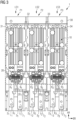
- FIG. 3 shows a plan view of a switching device 1 according to the invention with a power module 10 and a bridging unit 20 for a three-phase electrical load (not shown).
- the technical construction of the power module 10 with its respective power modules 10 1 , 10 2 and 10 3 for the phases P1, P2 and P3 does not differ from that in FIG 2 shown and described soft starter.
- the input and output-side connecting bars 2 1 and 3 1 of phase P1, 2 2 and 3 2 of phase P2 and 2 3 and 3 3 of phase P3 are connected on one side of the power module 10 are arranged next to one another in such a way that the connection bars 2 1 and 3 1 of phase P1, the connection bars 2 2 and 3 2 of phase P2 and the connection bars 2 3 and 3 3 of phase P3 are arranged next to one another in an extension direction ER .
- the direction of extension ER corresponds to the width direction and runs from left to right in the plane of the page.
- the connection rails 2 1 , 3 1 , 2 2 , 3 2 , 2 3 , 3 3 are arranged on the underside of the switching device 1 .
- connection rails 2 1 , 3 1 , 2 2 , 3 2 , 2 3 , 3 3 run transversely to the extension direction ER in a so-called arrangement direction AR (from top to bottom in the plane of the drawing).
- Adjacent to the power module 10, the connection bars 2 1 , 3 1 , 2 2 , 3 2 , 2 3 , 3 3 have respective first and second connection parts 8 1 , 9 1 , 8 2 , 9 2 , 8 3 , 9 3 in the shape of flat sections of the connection rails.
- a respective contact bridge 25 ( Figures 6 and 7 ) of the bridging units 20 1 , 20 2 and 20 3 of the electromechanical switching element assigned to a respective phase P1, P2, P3 runs in the extension direction ER in order to connect the first and the second connection part 8 1 , 9 1 of the phase P1 or 8 2 , 9 2 of phase P2 and 8 3 , 9 3 of phase P3 to be electrically connected to one another.
- the bridging units 20 1 , 20 2 , 20 3 provided for each phase of the entire bridging unit 20 are arranged below the power module 10 in a plan view, so that the connection bars 2 1 , 3 1 , 2 2 , 3 2 , 2 3 , 3 3 run parallel downwards transversely to the extension direction ER in the arrangement direction AR.
- the end sections 6 1 and 7 1 of the connecting bars 2 1 , 3 1 , the end sections 6 2 and 7 2 of the connecting bars 2 2 , 3 2 and the end sections 6 3 and 7 3 of the connecting bars 2 3 , 3 3 come to lie adjacent to one another . That the ends of the respective input-side connection bars 2 1 , 2 2 and 2 3 facing away from the power module 10 have a shorter length than that of the output-side Having connecting rails 3 1 , 3 2 and 3 3 is merely an optional embodiment.
- the power modules 10 1 , 10 2 , 10 3 and the associated bridging units 20 1 , 20 2 , 20 3 of a respective phase P1, P2, P3 are thus arranged one above the other in the arrangement direction AR, resulting in a small width. Since no space is required above the power module 10 for the connection of the switching device 1, for example for establishing an electrical connection, less space is also required in the vertical direction in comparison to the conventional switching device 1.
- the power module 10 and the bridging unit 20 are arranged in a common housing 30 in the exemplary embodiment shown here.
- the end sections 6 1 , 6 2 , 6 3 and 7 1 , 7 2 , 7 3 are also surrounded at least on one side by this common housing 30 .
- the power modules 10 1 , 10 2 , 10 3 and the bridging units 20 1 , 20 2 , 20 3 of a respective phase P1, P2, P3 are delimited laterally by partitions 31, 32, 33, 34 running in the arrangement direction AR. This ensures electrical insulation between the components of different phases.
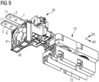
- the electrical components can be cooled in a simple manner, as shown in the perspective view of the components of a phase in 9 is shown.
- one fan element 40 is provided for each phase P1, P2, P3, with this in 9 is mechanically fastened to the connecting bars 2, 3 belonging to the relevant phase.
- the fan element 40 and the bridging unit 20 are arranged on opposite sides of the connecting rail 2, 3 belonging to the phase.
- a heat sink 13 arranged below the power module 10 and lying in an air flow generated by the fan element 40 in the arrangement direction can be well cooled. This is a particular effective Dissipation of the heat generated by the controllable semiconductor switching elements of the power module 10 is possible.
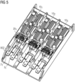
- the figures 4 and 5 show perspective views of the in 3 shown switching device (soft starter) from above.
- the current profile shown via the bridging module 20 1 is shown for the phase P1 with BS1 after the rated operating point of the working machine connected to the switching device has been reached.
- the current flows via the input-side connection bar 2 1 , the closed jumper that electrically connects the first connection part 8 1 to the second connection part 9 1 of the output-side bar 3 and the connection bar 3 1 back in the direction of the end section 7 1 .
- figure 5 shows the current flow during the start-up of the working machine for phase P1, the current flow being identified as BS2.
- the contact bridge is not connected to the first and the second connection part 8 1 of the connection bar 2 1 and 9 1 of the connection bar 3 1 , which is why the current flows via the power module 10 1 assigned in the arrangement direction AR and back via the output-side connection bar 3 1 .
- the controllable electromechanical switching element 21 1 of the bridging unit 20 1 is open.
- FIG. 6 12 shows a perspective view of a part of the switching device 1 for one phase. Since the structure for the three phases P1, P2, P3 is identical, in Figures 6, 7 and 8 the respective indices of the reference symbols are omitted.
- the heat sink 13 for example made of a metal, in particular aluminum, is arranged below the power module 10.
- the connection between the power module 10 and the heat sink 13 is made with good thermal conductivity, for example via a screw connection. It can be clearly seen that the connection bar 2 on the input side and the output bar 3 on the output side are brought up to the power module 10 from one side are. Adjacent to the power module 10, the bridging module 20 is on the top of the connecting bar 2, 3 arranged, from the parts in the Figures 7 and 8 are shown.
- FIG. 8 1 shows the coil holder 23 arranged on the upper side of the connecting bars 2 and 3, a magnetic coil 28 and a yoke 29, which are accommodated in the coil holder 23.
- Reference number 26 designates an armature, with a spring clip and a contact spring being arranged inside the contact carrier 22 running downwards in a manner known to those skilled in the art in order to prevent a movement of the contact bridge upwards and downwards and thus towards the connecting rails 2, 3 or from to enable this way.
- a current 28 flows through the magnetic coil, as a result of which the armature 26 is moved upwards. Due to the mechanical coupling, the contact bridge 25 is pressed with the contacts 27 upwards onto the connecting rails 2, 3. As soon as the current through the magnetic coil 28 is switched off, the spring running inside the contact carrier ensures that the contacts 27 of the contact bridge 25 are pushed away from the connecting parts 8, 9 of the connecting rails 2, 3.
- the contact carrier 22 thus serves to fix the contact bridge 25 of the contact spring of the spring clip of the armature and the like.
- the coil holder 23 is needed to hold the magnet coil 28 to hold the yoke 29 in position.
- a switching device designed as a soft starter can be built to be extremely compact.
- a connection to a bridging unit can be omitted. Reducing the current paths and contact points has a positive effect on the heat loss and the robustness of the device.
Landscapes
- Engineering & Computer Science (AREA)
- Microelectronics & Electronic Packaging (AREA)
- Physics & Mathematics (AREA)
- Thermal Sciences (AREA)
- Power Engineering (AREA)
- Electromagnetism (AREA)
- Inverter Devices (AREA)
- Rectifiers (AREA)
Description
- Die Erfindung betrifft eine Schaltvorrichtung für einen ein- oder mehrphasigen elektrischen Verbraucher. Die Schaltvorrichtung umfasst eine der Anzahl der Phasen entsprechende Anzahl an Leitungssträngen, wobei jeder Leitungsstrang ein als Eingang dienendes erstes Anschlussteil zur Verbindung mit einer Netzphase und ein als Ausgang dienendes zweites Anschlussteil zur Verbindung mit einer Phase des elektrischen Verbrauchers umfasst. Die Schaltvorrichtung umfasst ferner ein Leistungsmodul und eine Überbrückungseinheit. Das Leistungsmodul umfasst pro Phase zumindest ein steuerbares Halbleiterschaltelement, wobei das zumindest eine steuerbare Halbleiterschaltelement zwischen dem ersten und dem zweiten Anschlussteil verschaltet ist. Die Überbrückungseinheit umfasst pro Phase ein steuerbares elektromechanisches Schaltelement mit geringem Durchlasswiderstand, wobei das steuerbare elektromechanische Schaltelement, parallel zu dem zumindest einen steuerbaren Halbleiterschaltelement dieser Phase, zwischen dem ersten und dem zweiten Anschlussteil verschaltet ist.
- Eine derartige Schaltvorrichtung ist beispielsweise ein Sanftstarter für eine Arbeitsmaschine, insbesondere eine permanent erregte Drehstrommaschine. Das Leistungsmodul wird benötigt, um die Arbeitsmaschine gesteuert anlaufen zu lassen. Die Überbrückungseinheit dient dazu, die Verlustleistung beim Betrieb im Nennbetriebspunkt der Arbeitsmaschine möglichst gering zu halten. Die Minimierung der Verlustleistung wird dadurch realisiert, dass das Leistungsmodul nach Erreichen des Nennbetriebspunkts mit Hilfe der Überbrückungseinheit und den darin enthaltenen elektromechanischen Schaltelementen, überbrückt wird. Bei einem Sanftstarter wird die Überbrückungseinheit auch als "Bypass" bezeichnet, wobei die steuerbaren elektromechanischen Schaltelemente in Gestalt von Schützen oder Relais vorliegen. Die Überbrückungseinheit kann zusammen mit dem Leistungsmodul in einem gemeinsamen Gehäuse angeordnet sein. Es sind auch solche Sanftstarter bekannt, bei denen die Überbrückungseinheit und das Leistungsmodul in unterschiedlichen Gehäusen vorliegen und am Einsatzort durch entsprechende Verschaltung zu dem Sanftstarter kombiniert werden.
- Ein Nachteil einer derartigen Schaltvorrichtung ist es, dass durch die Verwendung der fertigen Teilkomponenten ein Aufbau nicht kompakt, d.h. mit geringen äußeren Abmaßen, realisiert werden kann. Hinzu kommt, dass insbesondere dann, wenn die Überbrückungseinheit und das Leistungsmodul in unterschiedlichen Gehäusen vorliegen, diese mit hohem Aufwand elektrisch miteinander verbunden werden müssen. Dieser Verdrahtungsaufwand kann sich negativ auf die im Betrieb entstehende Verlustwärme auswirken. In jedem Fall sind durch die aufwändigen Fertigungsschritte hohe Herstellkosten damit verbunden.
-
EP 1 037 515 A2 (Eaton Corp.) 20.09.2000 beschreibt einen Halbleiter-Motorstarter mit einem linearen Strompfad von einem Eingangsende (36) zu einem Ausgangsende (44) des Motorstarters. Dabei ist ein Lüfterelement (66), welches zur Kühlung Luft an einem Kühlkörper (64) entlang fördert, zwischen einem Bypass (50) und dem Kühlkörper (64) an einem Gehäusedeckel (12) des Motorstarters befestigt. -
US 4 943 890 A (Schaltenbrand, Robert W. et al.) 24.07.1990 beschreibt einen Motorstarter mit Halbleiter-Leistungsmodulen (3a, 3b) und einem Bypass (4a, 4b, 5), wobei die Stromanschlüsse (10, 10b) des Motorstarters auf einer gemeinsamen Seite des Motorstarters angeordnet sind. -
US 5 337 214 A (Lindsey, Kurt L. et al.) 09.08.1994 beschreibt einen Motorstarter mit Halbleiter-Leistungsmodulen (12, 14) und mindestens einem Bypass (30, 30'), wobei die Stromanschlüsse (26) des Motorstarters auf einer gemeinsamen Seite des Motorstarters angeordnet sind. - Es ist wünschenswert, eine Schaltvorrichtung der oben genannten Art bereitzustellen, welche durch konstruktive Maßnahmen einen geringen Verdrahtungsaufwand zwischen Leistungsmodul und Überbrückungseinheit nach sich zieht und gleichzeitig mit minimalen äußeren Abmaßen bereitgestellt werden kann.
- Diese Aufgabe wird gelöst durch eine Schaltvorrichtung gemäß den Merkmalen des Anspruchs 1. Vorteilhafte Ausgestaltungen ergeben sich aus den abhängigen Ansprüchen.
- Es wird eine Schaltvorrichtung für einen ein- oder mehrphasigen elektrischen Verbraucher vorgeschlagen. Die Schaltvorrichtung umfasst eine der Anzahl der Phasen entsprechende Anzahl an Leitungssträngen, wobei jeder Leitungsstrang ein als Eingang dienendes erstes Anschlussteil zur Verbindung mit einer Netzphase und ein als Ausgang dienendes zweites Anschlussteil zur Verbindung mit einer Anschlussphase des elektrischen Verbrauchers umfasst. Die Schaltvorrichtung umfasst ferner ein Leistungsmodul, das pro Phase zumindest ein steuerbares Halbleiterschaltelement umfasst, wobei das zumindest steuerbare Halbleiterschaltelement zwischen dem ersten und dem zweiten Anschlussteil verschaltet ist. Ferner umfasst die Schaltvorrichtung eine Überbrückungseinheit, die pro Phase ein steuerbares elektromechanisches Schaltelement mit geringem Durchlasswiderstand umfasst. Das steuerbare elektromechanische Schaltelement ist dabei, parallel zu dem zumindest einen steuerbaren Halbleiterschaltelement dieser Phase, zwischen dem ersten und dem zweiten Anschlussteil verschaltet.
- Die Schaltvorrichtung zeichnet sich dadurch aus, dass das erste und das zweite Anschlussteil einer jeweiligen Phase an einer Seite des Leistungsmoduls in räumlicher Nähe in einer Erstreckungsrichtung benachbart nebeneinander angeordnet sind. Ferner verläuft eine Kontaktbrücke des einer jeweiligen Phase zugeordneten elektromechanischen Schaltelements der Überbrückungseinheit in der Erstreckungsrichtung, um im angeschalteten Zustand des steuerbaren elektromechanischen Schaltelements das erste und das zweite Anschlussteil elektrisch zu verbinden.
- Die erfindungsgemäße Schaltvorrichtung ermöglicht einen kompakten und kostengünstigen Aufbau, indem das erste und das zweite Anschlussteil, an denen jeweilige Lastanschlüsse der Schaltelemente des Leistungsmoduls und der Überbrückungseinheit angeschlossen sind, auf einer Seite des Leistungsmoduls und in räumliche Nähe zueinander angeordnet werden. Dies ermöglicht es, das erste und das zweite Anschlussteil einer Phase nach dem Erreichen des Nennbetriebspunkts mittels einer Kontaktbrücke, die Teil des steuerbaren elektromechanischen Schaltelements einer Phase der Überbrückungseinheit ist, zu verbinden. Durch die in Erstreckungsrichtung verlaufende Kontaktbrücke können die Komponenten des Leistungsmoduls sehr einfach zu- oder weggeschaltet werden. Insbesondere ermöglicht es dieser Aufbau, den Verdrahtungsaufwand zwischen den Komponenten des Leistungsmoduls und der Überbrückungseinheit zu minimieren. Konstruktives Merkmal dieser Schaltvorrichtung ist es somit, dass sich die Ein- und Ausgänge der Schaltvorrichtung an einer Seite des Geräts befinden.
- Durch die Überbrückung des als Eingang dienenden ersten Anschlussteils und des als Ausgang dienenden zweiten Anschlussteils mittels der Kontaktbrücke können Stromwege verkürzt werden. Dies ermöglicht es, die Schaltvorrichtung kompakt aufzubauen. Insbesondere kann eine Verbindung zu der Überbrückungseinheit entfallen.
- Die Reduzierung der Stromwege und die Reduzierung der Kontaktstellen weisen darüber hinaus einen positiven Effekt auf die Verlustwärme und damit die Robustheit der Schaltvorrichtung auf.
- Eine zweckmäßige Ausgestaltung sieht vor, dass das Leistungsmodul und die Überbrückungseinheit in einem gemeinsamen Gehäuse angeordnet sind. Dies erleichtert die Handhabung der Schaltvorrichtung bei der Installation an einem Einsatzort, da lediglich die Schaltvorrichtung, z.B. an einer Leiterschiene befestigt werden braucht und die Netz- und die Anschlussphase mit den entsprechenden Leitungen verbunden werden müssen. Die Vornahme interner Verdrahtungen ist hierbei nicht erforderlich. Diese Ausgestaltung begünstigt einen kompakten Aufbau.
- Eine weitere Ausgestaltung sieht vor, dass das Leistungsmodul und die Überbrückungseinheit einer jeweiligen Phase in einer Anordnungsrichtung hintereinander angeordnet sind, wobei die Anordnungsrichtung quer zu der Erstreckungsrichtung verläuft. Dies ermöglicht einen schlanken Aufbau der Schaltvorrichtung, d.h. bei einer üblichen Befestigung an einer Leiterschiene weist die Schaltvorrichtung eine geringe Breite auf. Dadurch, dass das erste und das zweite Anschlussteil an einer Seite des Leistungsmoduls angeordnet sind und aus dem Gehäuse der Schaltvorrichtung herausgeführt werden können, kann der in der Höhe benötigte Platz zum Herstellen der Verbindung zur Netzphase und der Anschlussphase gering gehalten werden.
- Das Leistungsmodul und die Überbrückungseinheit einer jeweiligen Phase sind gemäß einer weiteren zweckmäßigen Ausgestaltung seitlich von in der Anordnungsrichtung verlaufenden Trennwänden begrenzt. Hierdurch ergibt sich einerseits eine Isolation der zu einer Phase zugehörigen Komponenten. Darüber hinaus kann andererseits die Entwärmung vereinfacht werden.
- Eine weitere Ausgestaltung sieht vor, dass das erste und das zweite Anschlussteil flächige Abschnitte von Anschlussschienen sind, deren Enden flächige Endabschnitte zur Verbindung mit Anschlusselementen der Netzphase bzw. Anschlussphase des Verbrauchers umfassen. Dadurch, dass das erste und das zweite Anschlussteil flächige Abschnitte von Anschlussschienen sind, können diese auf besonders einfache Weise mit Kontakten der Kontaktbrücke in elektrischen Kontakt gebracht werden, um im eingeschalteten Zustand des steuerbaren elektromechanischen Schaltelements der Überbrückungseinheit das erste und das zweite Anschlussteil elektrisch zu verbinden. Auf diese Weise lässt sich somit eine konstruktiv einfache Verbindung realisieren, wobei die Anschlusselemente Teil des Kontaktweges der Überbrückungseinheit darstellen.
- Es ist vorgesehen, dass die Schaltvorrichtung pro Phase ein Lüfterelement umfasst. In Verbindung mit den Trennwänden zwischen den Komponenten benachbart angeordneter Phasen kann ein gezielter Luftstrom in Richtung der sich im Betrieb erwärmenden Komponenten des Leistungsmoduls und der Überbrückungseinheit geführt werden. Hierdurch kann die in den Komponenten entstehende Wärme über die Luft abgeführt werden.
- Es ist weiterhin vorgesehen, dass das Lüfterelement an den, zu einer Phase gehörenden, Anschlussschienen mechanisch befestigt ist. Das Lüfterelement kann z.B. auf besonders einfache Weise durch eine lösbare Steckverbindung an den Anschlussschienen oder einem daran angebrachten Befestigungsteil angebracht werden. Insbesondere ist es nicht erforderlich, für das Lüfterelement an dem Gehäuse oder einem Gehäuseteil entsprechende integrale Komponenten vorzusehen.
- Es ist weiterhin zweckmäßig, wenn das Lüfterelement und die Überbrückungseinheit auf gegenüberliegenden Seiten der, zu einer Phase gehörenden, Anschlussschienen angeordnet sind. Dies ermöglicht einen kompakten Aufbau der Schaltvorrichtung.
- Eine weitere zweckmäßige Ausgestaltung sieht vor, dass ein von dem Lüfterelement erzeugbarer Luftstrom in der Anordnungsrichtung einen mit dem Leistungsmodul wärmeleitend verbundenen Kühlkörper anströmt. Dadurch, dass der Kühlkörper direkt in der Anordnungsrichtung des Luftstroms liegt, kann die an den Kühlkörper übertragene Wärme auf einfache Weise abgeführt werden.
- Eine andere Ausgestaltung sieht vor, dass die Kontaktbrücken des einer jeweiligen Phase zugeordneten elektromechanischen Schaltelements der Überbrückungseinheit einer mehrphasigen Schaltvorrichtung in einer gemeinsamen gedachten Linie der Erstreckungsrichtung angeordnet sind. Die jeweiligen Kontaktbrücken, die Teil des einer Phase zugeordneten elektromechanischen Schaltelements sind, liegen somit in Erstreckungsrichtung nebeneinander. Die elektromechanischen Schaltelemente jeweiliger Phasen sind voneinander getrennte Elemente, d.h. weisen keinen mechanischen Zusammenhang oder Verbindung auf.
- Es ist weiterhin zweckmäßig, wenn eine Überbrückungseinheit des einer jeweiligen Phase zugeordneten elektromechanischen Schaltelements dazu ausgebildet ist, die Kontaktbrücken mit dem ersten und dem zweiten Anschlusselement zu verbinden, wobei die Überbrückungseinheit in einem Zwischenraum zwischen dem ersten und dem zweiten Anschlussteil geführt ist. Diese Ausgestaltung ermöglicht eine kompakte Realisierung des elektromechanischen Schaltelements einer jeweiligen Phase. Neben einem einfachen und robusten mechanischen Aufbau kann darüber hinaus ein kompaktes Schaltelement und damit eine kompakte Schaltvorrichtung bereitgestellt werden.
- Insbesondere umfasst die Schaltvorrichtung ein Leistungsmodul und eine Überbrückungseinheit zur Schaltung von dreiphasigen Verbrauchern. In einer besonders zweckmäßigen Ausgestaltung ist die Schaltvorrichtung ein Sanftstarter für eine Arbeitsmaschine in Gestalt einer, insbesondere permanent erregten, Drehstrommaschine.
- Die Erfindung wird nachfolgend näher anhand eines Ausführungsbeispiels in der Zeichnung erläutert. Es zeigen:
- Fig. 1
- ein elektrisches Ersatzschaltbild einer Schaltvorrichtung für einen ein- oder mehrphasigen elektrischen Verbraucher;
- Fig. 2
- eine schematische Darstellung auf eine aus dem Stand der Technik bekannte Schaltvorrichtung in einer Draufsicht;
- Fig. 3
- eine erfindungsgemäße Schaltvorrichtung für einen dreiphasigen elektrischen Verbraucher in einer Draufsicht;
- Figs. 4 und 5
- jeweils eine perspektivische Darstellung der in
Fig. 3 gezeigten erfindungsgemäßen Schaltvorrichtung, wobei die in zwei unterschiedlichen Betriebszuständen auftretenden Strompfade illustriert sind; - Fig. 6
- eine perspektivische Darstellung einer erfindungsgemäßen Kombination eines Leistungsmoduls und einer Überbrückungseinheit für eine Phase;
- Fig. 7
- eine schematische Darstellung eines Teils einer Übertragereinheit;
- Fig. 8
- eine Komponente einer erfindungsgemäßen Überbrückungseinheit in einer perspektivischen Darstellung; und
- Fig. 9
- eine perspektivische Darstellung einer Kombination von Leistungsmodul und Überbrückungseinheit mit einem Lüfterelement.
- In den nachfolgend beschriebenen Figuren bezeichnen gleiche Bezugszeichen gleiche Elemente.
-
Fig. 1 zeigt eine schematische Darstellung eines Ersatzschaltbilds einer Schaltvorrichtung für einen dreiphasigen elektrischen Verbraucher. Die Schaltvorrichtung wird nachfolgend anhand eines Sanftstarters beschrieben, wobei dies jedoch nicht als beschränkend zu betrachten ist. Der elektrische Verbraucher stellt z.B. eine Arbeitsmaschine, insbesondere eine permanent erregte Drehstrommaschine dar. In einem jeweiligen Leitungsstrang LS1, LS2, LS3 jeder der Phasen P1, P2, P3 ist ein Schaltmodul angeordnet. Jedes Schaltmodul umfasst ein Leistungsmodul 101, 102 bzw. 103 und eine Überbrückungseinheit 201, 202 bzw. 203. Der in den Figuren einem Bezugszeichen nachgeordneter Index "1", "2" oder "3" bezeichnet dabei das jeweilige Element der Phase P1, P2 oder P3. - In einem jeweiligen Schaltmodul umfasst das Leistungsmodul 101, 102, 103 zwei antiparallel verschaltete steuerbare Halbleiterschaltelemente 111 und 121, 112 und 122 sowie 113 und 123. Parallel zu den steuerbaren Halbleiterschaltelementen 111 und 121, 112 und 122 sowie 113 und 123 ist pro Phase ein steuerbares elektromechanisches Schaltelement 211, 212 bzw. 213 vorgesehen, das Bestandteil der Überbrückungseinheit 201, 202 bzw. 203 ist. Die Überbrückungseinheit 201, 202 bzw. 203, die auch als Bypass bezeichnet wird, umfasst als steuerbares elektromechanisches Schaltelement in der Regel ein Schütz oder Relais. Die Überbrückungseinheit 201, 202 bzw. 203 dient dazu, nach dem Starten der Arbeitsmaschine durch Ansteuerung der Schaltelemente des Leistungsmoduls 101, 102, 103, die Verlustleistung des Schaltmoduls beim Nennbetriebspunkt der Arbeitsmaschine möglichst gering zu halten. Hierzu werden die steuerbaren elektromechanischen Schaltelemente 211, 212 bzw. 213 der Überbrückungsmodule 20 nach dem Erreichen des Nennbetriebspunkts der Arbeitsmaschine leitend geschaltet, wodurch die steuerbaren Halbleiterschaltelemente 111 und 121, 112 und 122 sowie 113 und 123 der Leistungsmodule 101, 102, 103 überbrückt sind. Der in Verbindung mit
Fig. 1 beschriebene Aufbau des Schaltmoduls, das in allen drei Phasen identisch aufgebaut ist, entspricht der prinzipiellen elektrischen Verschaltung eines Sanftstarters. -
Fig. 2 zeigt eine Draufsicht auf einen aus dem Stand der Technik bekannten Sanftstarter als Schaltvorrichtung für einen dreiphasigen Verbraucher. - Das mit dem Bezugszeichen 10 als Ganzes gekennzeichnete Leistungsmodul umfasst hierbei die in
Fig. 1 dargestellten Leistungsmodule 101, 102 und 103 mit den jeweils zwei antiparallel geschalteten steuerbaren Halbleiterschaltelementen 111 und 121, 112 und 122 sowie 113 und 123 (nicht gesondert gekennzeichnet). Das Leistungsmodul 10, das in der gezeigten beispielhaften Bauform die Gesamtheit der steuerbaren Halbleiterschaltelemente für die drei Phasen P1, P2, P3 vereinigt, kann in einem eigenständigen Gehäuse vorgesehen sein. - Die Schaltvorrichtung 1 umfasst darüber hinaus die mit dem Bezugszeichen 20 als Ganzes gekennzeichnete Überbrückungseinheit, die die in der schematischen Darstellung der
Fig. 1 gezeigten Überbrückungseinheiten 201, 202 und 203 mit den jeweiligen steuerbaren elektromechanischen Schaltelementen 211, 212 und 213 umfasst. Die Überbrückungseinheit 20 kann in einem eigenständigen Gehäuse realisiert sein. - In der in
Fig. 2 dargestellten Ausgestaltungsvariante sind das Leistungsmodul 10 und die Überbrückungseinheit 20 exemplarisch in einem gemeinsamen Gehäuse 30 in Breitenrichtung nebeneinander (d.h. in der Blattebene von links nach rechts) angeordnet. - Oberhalb und unterhalb der Überbrückungseinheit 20 (d.h. in der Blattebene oberhalb und unterhalb) führen Anschlussschienen 21, 22 und 23 sowie 31, 32 und 33 an das heran bzw. in das Gehäuse 30 hinein. Für jede Phase P1, P2, P3 ist dabei eine jeweilige eingangsseitige Anschlussschiene 21, 22, 23 sowie eine ausgangsseitige Anschlussschiene 31, 32, 33 vorgesehen. An Endabschnitten 61, 62, 63 der eingangsseitigen Anschlussschiene 21, 22, 23 (in Blattebene oben) erfolgt eine Verbindung mit einer Netzphase L1, L2 bzw. L3. An Endabschnitten 71, 72, 73 der ausgangsseitigen Anschlussschienen 31, 32, 33 (in Blattebene unten) erfolgt eine elektrische Verbindung mit einer Anschlussphase T1, T2 und T3 des hier nicht dargestellten elektrischen Verbrauchers, d.h. der Arbeitsmaschine.
- Zur Realisierung der Parallelschaltung jeweiliger steuerbarer elektromechanischer Schaltelemente 211, 212, 213 mit den steuerbaren Halbleiterschaltelementen 111 und 121 der Phase P1, 112 und 122 der Phase P2 sowie 113 und 123 der Phase P3 sind Verbindungsschienen 41, 42, 43 sowie Verbindungskabel 51, 52, 53 vorgesehen. Die auf der Eingangsseite vorgesehenen Verbindungsschienen 41, 42, 43 liegen dabei in der dargestellten Draufsicht übereinander, d.h. weisen untereinander keinerlei elektrische Verbindung auf. Gegebenenfalls kann ein Isolationsmaterial in den Abschnitten, in denen zwei Verbindungsschienen übereinander angeordnet sind, vorgesehen sein. Die ausgangsseitigen Anschlussschienen 31, 32, 33 sind in diesem Ausführungsbeispiel über Verbindungskabel 51, 52, 53 und jeweilige endseitige Kabelschuhe miteinander verbunden. Dem Fachmann ist klar, dass diese Verschaltung lediglich beispielhaft ist und ausschließlich Verbindungsschienen oder Verbindungskabel zum Einsatz kommen könnten.
- Es ist ohne weiteres ersichtlich, dass die Verwendung der als separate Einheiten vorliegenden Leistungsmoduls 10 und Überbrückungseinheit 20 sowie notwendige Verdrahtungen zur Ausbildung jeweiliger Leitungsstränge LS1, LS2, LS3 für die drei Phasen P1, P2, P3 mit einem hohen Aufwand verbunden ist. Hieraus resultiert auch ein unerwünschter, nicht kompakter Aufbau, wobei insbesondere ein großer Bauraum in der Breite (d.h. in der Blattebene von links nach rechts) erforderlich ist.
- Die nachfolgend in den
Fig. 3 bis 5 dargestellte erfindungsgemäße Schaltvorrichtung ist demgegenüber mit größerer Kompaktheit und geringerem Verdrahtungsaufwand bereitgestellt.Fig. 3 zeigt hierbei eine Draufsicht auf eine erfindungsgemäße Schaltvorrichtung 1 mit einem Leistungsmodul 10 sowie einer Überbrückungseinheit 20 für einen dreiphasigen elektrischen Verbraucher (nicht dargestellt). - Der technische Aufbau des Leistungsmoduls 10 mit seinen jeweiligen Leistungsmodulen 101, 102 und 103 für die Phasen P1, P2 und P3 unterscheidet sich nicht von dem in
Fig. 2 gezeigten und beschriebenen Sanftstarter. Im Unterschied zu der aus dem Stand der Technik bekannten Variante werden jedoch die ein- und ausgangsseitigen Anschlussschienen 21 und 31 der Phase P1, 22 und 32 der Phase P2 und 23 und 33 der Phase P3 an einer Seite des Leistungsmoduls 10 derart benachbart nebeneinander angeordnet, wodurch die Anschlussschienen 21 und 31 der Phase P1, die Anschlussschienen 22 und 32 der Phase P2 und die Anschlussschienen 23 und 33 der Phase P3 in einer Erstreckungsrichtung ER nebeneinander angeordnet sind. Die Erstreckungsrichtung ER entspricht der Breitenrichtung und verläuft in der Blattebene von links nach rechts. Im vorliegenden Ausführungsbeispiel sind die Anschlussschienen 21, 31, 22, 32, 23, 33 an der Unterseite der Schaltvorrichtung 1 angeordnet. - Die Anschlussschienen 21, 31, 22, 32, 23, 33 verlaufen dabei quer zu der Erstreckungsrichtung ER in einer sog. Anordnungsrichtung AR (in der Blattebene von oben nach unten). Benachbart zu dem Leistungsmodul 10 weisen die Anschlussschienen 21, 31, 22, 32, 23, 33 jeweilige erste und zweite Anschlussteile 81, 91, 82, 92, 83, 93 in Gestalt von flächigen Abschnitten der Anschlussschienen auf. Eine jeweilige Kontaktbrücke 25 (
Figuren 6 und 7 ) der Überbrückungseinheiten 201, 202 und 203 des einer jeweiligen Phase P1, P2, P3 zugeordneten elektromechanischen Schaltelements verläuft dabei in der Erstreckungsrichtung ER, um im eingeschalteten Zustand das erste und das zweite Anschlussteil 81, 91 der Phase P1 bzw. 82, 92 der Phase P2 bzw. 83, 93 der Phase P3 elektrisch miteinander zu verbinden. - Dies bedeutet, dass die pro Phase vorgesehenen Überbrückungseinheiten 201, 202, 203 der gesamten Überbrückungseinheit 20 in Draufsicht unterhalb des Leistungsmoduls 10 angeordnet sind, so dass die Anschlussschienen 21, 31, 22, 32, 23, 33 quer zur Erstreckungsrichtung ER in der Anordnungsrichtung AR parallel nach unten verlaufen. Infolgedessen kommen die Endabschnitte 61 und 71 der Anschlussschienen 21, 31, die Endabschnitte 62 und 72 der Anschlussschienen 22, 32 sowie die Endabschnitte 63 und 73 der Anschlussschienen 23, 33 benachbart nebeneinander zum Liegen. Dass die von dem Leistungsmodul 10 abgewandten Enden jeweiliger eingangsseitiger Anschlussschienen 21, 22 und 23 eine geringe Länge als die der ausgangsseitigen Anschlussschienen 31, 32 und 33 aufweisen, ist lediglich eine optionale Ausgestaltungsform.
- Die Leistungsmodule 101, 102, 103 und die zugeordneten Überbrückungseinheiten 201, 202, 203 einer jeweiligen Phase P1, P2, P3 sind damit in der Anordnungsrichtung AR übereinander angeordnet, wodurch sich eine geringe Breite ergibt. Da für den Anschluss der Schaltvorrichtung 1 oberhalb des Leistungsmoduls 10 kein Platz, z.B. zur Herstellung einer elektrischen Verbindung, benötigt wird, wird im Vergleich zu der herkömmlichen Schaltvorrichtung 1 auch in Höhenrichtung weniger Platz benötigt.
- Das Leistungsmodul 10 und die Überbrückungseinheit 20 sind im hier gezeigten Ausführungsbeispiel in einem gemeinsamen Gehäuse 30 angeordnet. Von diesem gemeinsamen Gehäuse 30 sind auch die Endabschnitte 61, 62, 63 und 71, 72, 73 zumindest von einer Seite umgeben.
- Die Leistungsmodule 101, 102, 103 und die Überbrückungseinheiten 201, 202, 203 einer jeweiligen Phase P1, P2, P3 sind seitlich von in der Anordnungsrichtung AR verlaufenden Trennwänden 31, 32, 33, 34 begrenzt. Hierdurch ist eine elektrische Isolation zwischen den Komponenten unterschiedlicher Phasen sichergestellt. Gleichzeitig kann auf einfache Weise eine Kühlung der elektrischen Komponenten erfolgen wie in der perspektivischen Darstellung der Komponenten einer Phase in
Fig. 9 dargestellt ist. Grundsätzlich ist pro Phase P1, P2, P3 ein Lüfterelement 40 vorgesehen, wobei dieses inFig. 9 an den zu der betreffenden Phase gehörigen Anschlussschienen 2, 3 mechanisch befestigt ist. Das Lüfterelement 40 und die Überbrückungseinheit 20 sind dabei auf gegenüberliegenden Seiten der zu der Phase gehörenden Anschlussschiene 2, 3 angeordnet. Dadurch kann insbesondere ein unterhalb des Leistungsmoduls 10 angeordneter Kühlkörper 13, der in einem von dem Lüfterelement 40 erzeugten Luftstrom in der Anordnungsrichtung liegt, gut gekühlt werden. Damit ist insbesondere eine effektive Abfuhr der von den steuerbaren Halbleiterschaltelementen des Leistungsmoduls 10 erzeugten Wärme möglich. - Die
Figuren 4 und5 zeigen perspektivische Darstellungen der inFig. 3 gezeigten Schaltvorrichtung (Sanftstarter) von oben. InFig. 4 ist dabei für die Phase P1 mit BS1 der über das Überbrückungsmodul 201 gezeigte Stromverlauf nach dem Erreichen des Nennbetriebspunkts der an die Schaltvorrichtung angeschlossenen Arbeitsmaschine gezeigt. Der Strom fließt über die eingangsseitige Anschlussschiene 21, die geschlossene Schaltbrücke, die das erste Anschlussteil 81 elektrisch mit dem zweiten Anschlussteil 91 der ausgangsseitigen Schiene 3 verbindet und die Anschlussschiene 31 zurück in Richtung des Endabschnitts 71. -
Fig. 5 zeigt den Stromfluss während des Anlaufens der Arbeitsmaschine für die Phase P1, wobei der Stromfluss mit BS2 gekennzeichnet ist. Dabei ist die Kontaktbrücke nicht mit dem ersten und dem zweiten Anschlussteil 81 der Anschlussschiene 21 und 91 der Anschlussschiene 31 verbunden, weswegen der Strom über das in Anordnungsrichtung AR zugeordnete Leistungsmodul 101 und zurück über die ausgangsseitige Anschlussschiene 31 fließt. In der inFig. 5 gezeigten Betriebssituation ist somit das steuerbare elektromechanische Schaltelement 211 der Überbrückungseinheit 201 geöffnet. -
Fig. 6 zeigt eine perspektivische Darstellung eines Teils der Schaltvorrichtung 1 für eine Phase. Da der Aufbau für die drei Phasen P1, P2, P3 identisch ist, sind inFig. 6, 7 und 8 die jeweiligen Indizes der Bezugszeichen weggelassen. - Wie erwähnt, ist unterhalb des Leistungsmoduls 10 der Kühlkörper 13, z.B. aus einem Metall, insbesondere Aluminium, angeordnet. Die Verbindung zwischen Leistungsmodul 10 und Kühlkörper 13 erfolgt gut wärmeleitend, z.B. über eine Verschraubung. Gut ersichtlich ist, sind die eingangsseitige Anschlussschiene 2 und die ausgangsseitige Ausgangsschiene 3 von einer Seite her an das Leistungsmodul 10 herangeführt sind. Benachbart zu dem Leistungsmodul 10 ist auf der Oberseite der Anschlussschiene 2, 3 das Überbrückungsmodul 20 angeordnet, von dem Teile in den
Fig. 7 und 8 dargestellt sind. -
Fig. 8 zeigt dabei den auf der Oberseite der Anschlussschienen 2 und 3 angeordneten Spulenhalter 23, eine Magnetspule 28 sowie ein Joch 29, die in dem Spulenhalter 23 aufgenommen sind. In einem zwischen den Anschlussschienen 2 und 3 gebildeten Zwischenraum ist ein in dem Spulenhalter 23 aufgenommener Kontaktträger 22 (Fig. 7 ) als Übertragereinheit durchgeführt, an dessen unteren Ende die Kontaktbrücke 25 mit an gegenüberliegenden Enden angeordneten Kontakten 27 vorgesehen ist. Die Kontakte 27 kommen dabei, wie oben beschrieben, mit dem ersten Anschlussteil 8 der Anschlussschiene 2 und dem zweiten Anschlussteil 9 der Anschlussschiene 3 in Kontakt, wenn die Überbrückungseinheit 20 durch ein entsprechendes Ansteuersignal eingeschaltet ist. Das Bezugszeichen 26 bezeichnet einen Anker, wobei im Inneren des nach unten verlaufenden Kontaktträgers 22 in einer dem Fachmann bekannten Weise ein Federbügel sowie eine Kontaktfeder angeordnet sind, um eine Bewegung der Kontaktbrücke nach oben und unten und damit zu den Anschlussschienen 2, 3 hin oder von diesen weg zu ermöglichen. - Bei entsprechender Ansteuerung durch eine in den Figuren nicht gezeigte Steuerung fließt durch die Magnetspule ein Strom 28, wodurch der Anker 26 nach oben bewegt wird. Aufgrund der mechanischen Kopplung wird die Kontaktbrücke 25 mit den Kontakten 27 nach oben an die Anschlussschienen 2, 3 gedrückt. Sobald der Strom durch die Magnetspule 28 ausgeschaltet ist, sorgt die im Inneren des Kontaktträgers verlaufende Feder dafür, dass die Kontakte 27 der Kontaktbrücke 25 von den Anschlussteilen 8, 9 der Anschlussschienen 2, 3 weggedrückt werden.
- Der Kontaktträger 22 dient somit zur Fixierung der Kontaktbrücke 25 der Kontaktfeder der Federbügel des Ankers und dergleichen. Der Spulenhalter 23 wird benötigt, um die Magnetspule 28 um das Joch 29 in Position zu halten. Durch diesen kompakten Aufbau kann die Verlustwärme, die durch die elektrischen Widerstände der Anschlussschienen und Kontaktübergänge entsteht, reduziert werden.
- Im Ergebnis kann eine als Sanftstarter ausgebildete Schaltvorrichtung äußerst kompakt gebaut werden. Eine Verbindung zu einer Überbrückungseinheit kann entfallen. Die Reduzierung der Stromwege und die Reduzierung der Kontaktstellen haben einen positiven Effekt auf die Verlustwärme und die Robustheit des Geräts.
- Durch den Einbau der Überbrückungskomponenten in den Lüftungsstrang der Leistungsmodule kann auf eine zusätzliche Kühlung der Bypasskontakte durch eine Zwangsbelüftung verzichtet werden. Auch hierdurch ergibt sich ein positiver Einfluss auf die Herstellkosten der Schaltvorrichtung.
Claims (11)
- Schaltvorrichtung für einen ein- oder mehrphasigen elektrischen Verbraucher, umfassend- eine der Anzahl der Phasen (P1,P2,P3) entsprechende Anzahl an Leitungssträngen (LS1,LS2,LS3), wobei jeder Leitungsstrang (LS1,LS2,LS3) ein als Eingang dienendes erstes Anschlussteil (8) zur Verbindung mit einer Netzphase (L1,L2,L3) und ein als Ausgang dienendes zweites Anschlussteil (9) zur Verbindung mit einer Anschlussphase (T1,T2,T3) des elektrischen Verbrauchers umfasst;- ein Leistungsmodul (10), das pro Phase (P1,P2,P3) zumindest ein steuerbares Halbleiterschaltelement (111, 112, 113, 121, 122, 123) umfasst, wobei das zumindest eine steuerbare Halbleiterschaltelement (111, 112, 113, 121, 122, 123) zwischen dem ersten und dem zweiten Anschlussteil (8, 9) verschaltet ist;- eine Überbrückungseinheit (20), die pro Phase (P1,P2,P3) ein steuerbares elektromechanisches Schaltelement (211, 212, 213) mit geringem Durchlasswiderstand umfasst, wobei das steuerbare elektromechanische Schaltelement (211, 212, 213), parallel zu dem zumindest einen steuerbaren Halbleiterschaltelement (111, 112, 113, 121, 122, 123) dieser Phase (P1,P2,P3), zwischen dem ersten und dem zweiten Anschlussteil (8, 9) verschaltet ist;
wobei- das erste und das zweite Anschlussteil (8, 9) einer jeweiligen Phase (P1,P2,P3) an einer Seite des Leistungsmoduls (10) in räumlicher Nähe in einer Erstreckungsrichtung (ER) benachbart nebeneinander angeordnet sind,- eine Kontaktbrücke (25) des einer jeweiligen Phase (P1,P2,P3) zugeordneten elektromechanischen Schaltelements (211, 212, 213) der Überbrückungseinheit (20) in der Erstreckungsrichtung (ER) verläuft, um im eingeschalteten Zustand das erste und das zweite Anschlussteil (8, 9) elektrisch zu verbinden,dadurch gekennzeichnet,
dass die Schaltvorrichtung pro Phase (P1,P2,P3) ein Lüfterelement (40) umfasst, welches an zu einer Phase (P1,P2,P3) gehörenden Anschlussschienen (2, 3) mechanisch befestigt ist. - Schaltvorrichtung nach Anspruch 1, dadurch gekennzeichnet, dass das Leistungsmodul (10) und die Überbrückungseinheit (20) in einem gemeinsamen Gehäuse (30) angeordnet sind.
- Schaltvorrichtung nach Anspruch 1 oder 2, dadurch gekennzeichnet, dass das Leistungsmodul (10) und die Überbrückungseinheit (20) einer jeweiligen Phase (P1,P2,P3) hintereinander in einer Anordnungsrichtung (AR) angeordnet sind, die quer zu der Erstreckungsrichtung (ER) verläuft.
- Schaltvorrichtung nach Anspruch 3, dadurch gekennzeichnet, dass das Leistungsmodul (10) und die Überbrückungseinheit (20) einer jeweiligen Phase (P1,P2,P3) seitlich von in der Anordnungsrichtung (AR) verlaufenden Trennwänden (31,32,33,34) begrenzt sind.
- Schaltvorrichtung nach einem der vorhergehenden Ansprüche, dadurch gekennzeichnet, dass das erste und das zweite Anschlussteil (8, 9) flächige Abschnitte von Anschlussschienen (2,3) sind, deren Enden flächige Endabschnitte (6,7) zur Verbindung mit Anschlusselementen der Netzphase (L1,L2,L3) bzw. der Anschlussphase (T1,T2,T3) des Verbrauchers umfassen.
- Schaltvorrichtung nach Anspruch 1, dadurch gekennzeichnet, dass das Lüfterelement (40) und die Überbrückungseinheit (20) auf gegenüberliegenden Seiten der, zu einer Phase (P1,P2,P3) gehörenden, Anschlussschienen (2,3) angeordnet sind.
- Schaltvorrichtung nach einem der vorhergehenden Ansprüche, dadurch gekennzeichnet, dass ein von dem Lüfterelement (40) erzeugbarer Luftstrom in der Anordnungsrichtung (AR) einen mit dem Leistungsmodul (10) wärmeleitend verbundenen Kühlkörper (13) anströmt.
- Schaltvorrichtung nach einem der vorhergehenden Ansprüche, dadurch gekennzeichnet, dass die Kontaktbrücken (25) des einer jeweiligen Phase (P1,P2,P3) zugeordneten elektromechanischen Schaltelements (211, 212, 213) der Überbrückungseinheit (20) einer mehrphasigen Schaltvorrichtung in einer gemeinsamen gedachten Linie der Erstreckungsrichtung (ER) angeordnet sind.
- Schaltvorrichtung nach einem der vorhergehenden Ansprüche, dadurch gekennzeichnet, dass eine Übertragereinheit (22, 26) des einer jeweiligen Phase (P1,P2,P3) zugeordneten elektromechanischen Schaltelements (211, 212, 213) dazu ausgebildet ist, die Kontaktbrücke (25) mit dem ersten und dem zweiten Anschlussteil (8, 9) zu verbinden, wobei die Übertragereinheit in einem Zwischenraum zwischen dem ersten und dem zweiten Anschlussteil geführt ist.
- Schaltvorrichtung nach einem der vorhergehenden Ansprüche, dadurch gekennzeichnet, dass diese ein Leistungsmodul (10) und eine Überbrückungseinheit (20) zur Schaltung von drei Phasen (P1,P2,P3) umfasst.
- Schaltvorrichtung nach einem der vorhergehenden Ansprüche, dadurch gekennzeichnet, dass diese ein Sanftstarter für eine, insbesondere permanenterregte, Drehstrommaschine, ist.
Priority Applications (3)
| Application Number | Priority Date | Filing Date | Title |
|---|---|---|---|
| EP19160214.3A EP3703242B1 (de) | 2019-03-01 | 2019-03-01 | Schaltvorrichtung für einen ein- oder mehrphasigen elektrischen verbraucher |
| US16/802,745 US11425835B2 (en) | 2019-03-01 | 2020-02-27 | Switching device for a single-phase or multiphase electrical consumer |
| CN202010134298.0A CN111641327B (zh) | 2019-03-01 | 2020-03-02 | 用于单相或多相耗电器的开关装置 |
Applications Claiming Priority (1)
| Application Number | Priority Date | Filing Date | Title |
|---|---|---|---|
| EP19160214.3A EP3703242B1 (de) | 2019-03-01 | 2019-03-01 | Schaltvorrichtung für einen ein- oder mehrphasigen elektrischen verbraucher |
Publications (2)
| Publication Number | Publication Date |
|---|---|
| EP3703242A1 EP3703242A1 (de) | 2020-09-02 |
| EP3703242B1 true EP3703242B1 (de) | 2023-04-26 |
Family
ID=65657340
Family Applications (1)
| Application Number | Title | Priority Date | Filing Date |
|---|---|---|---|
| EP19160214.3A Active EP3703242B1 (de) | 2019-03-01 | 2019-03-01 | Schaltvorrichtung für einen ein- oder mehrphasigen elektrischen verbraucher |
Country Status (3)
| Country | Link |
|---|---|
| US (1) | US11425835B2 (de) |
| EP (1) | EP3703242B1 (de) |
| CN (1) | CN111641327B (de) |
Families Citing this family (2)
| Publication number | Priority date | Publication date | Assignee | Title |
|---|---|---|---|---|
| CN112437576B (zh) * | 2020-11-24 | 2022-01-07 | 汪清县振发投资有限公司 | 一种光伏发电用逆变器散热装置 |
| CN113541509B (zh) * | 2021-08-19 | 2022-10-21 | 西安西电电力系统有限公司 | 集成轻型化功率模块的柔直悬吊阀塔 |
Family Cites Families (13)
| Publication number | Priority date | Publication date | Assignee | Title |
|---|---|---|---|---|
| US4943890A (en) * | 1989-07-19 | 1990-07-24 | Benshaw, Inc. | Solid state motor starter |
| US5337214A (en) * | 1993-05-03 | 1994-08-09 | Eaton Corporation | Bypass contactor for solid state motor starters |
| US6208111B1 (en) * | 1997-10-21 | 2001-03-27 | Kevin R. Williams | Motor starter arrangement with soft start electronic control |
| US6087800A (en) * | 1999-03-12 | 2000-07-11 | Eaton Corporation | Integrated soft starter for electric motor |
| DE102004017292A1 (de) * | 2004-04-05 | 2005-10-20 | Siemens Ag | Motorsteuergerät |
| CN2765384Y (zh) * | 2005-01-24 | 2006-03-15 | 天津市诺尔电气有限公司 | 内置旁路型电动机软启动装置 |
| US7239513B2 (en) * | 2005-04-22 | 2007-07-03 | Saul Lin | Power control device |
| US7643256B2 (en) * | 2006-12-06 | 2010-01-05 | General Electric Company | Electromechanical switching circuitry in parallel with solid state switching circuitry selectively switchable to carry a load appropriate to such circuitry |
| CN101304228B (zh) * | 2008-03-24 | 2010-12-01 | 苏绵朋 | 一种铠装隔爆型开关变压器式软起动装置 |
| CN102820836B (zh) * | 2012-03-21 | 2016-02-24 | 上海人民企业集团温州电器有限公司 | 一种智能型电机软起动器 |
| CN205509895U (zh) * | 2015-12-03 | 2016-08-24 | 上海雷诺尔科技股份有限公司 | 适用于高压软起动器的散热结构 |
| US10014804B1 (en) * | 2017-07-07 | 2018-07-03 | Eaton Intelligent Power Limited | Motor starting methods and apparatus using output voltage control based on source voltage |
| CN108551280B (zh) * | 2018-06-14 | 2024-04-19 | 浙江硕仕电气科技有限公司 | 一种软启动装置及具有其的软启动柜 |
-
2019
- 2019-03-01 EP EP19160214.3A patent/EP3703242B1/de active Active
-
2020
- 2020-02-27 US US16/802,745 patent/US11425835B2/en active Active
- 2020-03-02 CN CN202010134298.0A patent/CN111641327B/zh active Active
Also Published As
| Publication number | Publication date |
|---|---|
| EP3703242A1 (de) | 2020-09-02 |
| CN111641327B (zh) | 2023-11-24 |
| US20200281088A1 (en) | 2020-09-03 |
| CN111641327A (zh) | 2020-09-08 |
| US11425835B2 (en) | 2022-08-23 |
Similar Documents
| Publication | Publication Date | Title |
|---|---|---|
| EP1281189B1 (de) | Steuereinrichtung | |
| DE60120813T2 (de) | Elektrischer Verbindungskasten für Kraftfahrzeuge | |
| EP1618580B1 (de) | Elektromechanisches schaltgerät | |
| EP3545538B1 (de) | Kondensator, insbesondere zwischenkreiskondensator für ein mehrphasensystem | |
| DE69201996T2 (de) | Mechanische und elektrische Zusammenfassungsvorrichtung für umspritzte Miniaturgehäuse. | |
| DE3843359C2 (de) | ||
| DE202011005667U1 (de) | Kompakte Sammelschienenanordnung, Schaltvorrichtung und Stromverteilungssytem | |
| EP3703242B1 (de) | Schaltvorrichtung für einen ein- oder mehrphasigen elektrischen verbraucher | |
| DE102022206596B4 (de) | Einzelphasenmodul eines Inverters, Inverter und Leistungselektronik | |
| DE69209443T2 (de) | Schaltfeld | |
| DE112018005842T5 (de) | Motorsteuerungssystem mit integriertem festkörperschütz und relais und verfahren zu dessen betrieb | |
| EP1362405B1 (de) | Stellvorrichtung für einen motor | |
| DE60030237T2 (de) | Drehstromschaltgerät mit kompensiertem Magnetkreis, insbesondere für Starkstrom mit zwei Polen pro Phase | |
| DE69510317T2 (de) | Metallgekapselte gasisolierte Schaltvorrichtung | |
| EP1733600B1 (de) | Motorsteuergerät | |
| EP1203442B1 (de) | Kombination eines schützes mit einem sanftanlasser | |
| EP2031623B1 (de) | Stromwandlerbaugruppe mit einer Phasenwendeverdrahtung sowie Schaltgerät mit einer derartigen Wandlerbaugruppe | |
| DE10147472A1 (de) | Stromrichtergerät | |
| DE102022206601B4 (de) | Einzelphasenmodul eines Inverters, Inverter und Leistungselektronik | |
| DE69122047T2 (de) | Elektrisches Gerät zum Anschliessen an eine Printplatte | |
| DE202007013483U1 (de) | Verbindungsklemmenblock für elektrische Mehrphasenmotoren | |
| EP3430874B1 (de) | Phasenmodul für einen stromrichter | |
| DE19530947A1 (de) | Klemmblock für Elektrizitätszähler | |
| DE102020126340B4 (de) | Wechselrichter für eine Antriebseinrichtung eines elektrisch antreibbaren Kraftfahrzeugs | |
| DE19713857C1 (de) | Starterkombination |
Legal Events
| Date | Code | Title | Description |
|---|---|---|---|
| PUAI | Public reference made under article 153(3) epc to a published international application that has entered the european phase |
Free format text: ORIGINAL CODE: 0009012 |
|
| STAA | Information on the status of an ep patent application or granted ep patent |
Free format text: STATUS: THE APPLICATION HAS BEEN PUBLISHED |
|
| AK | Designated contracting states |
Kind code of ref document: A1 Designated state(s): AL AT BE BG CH CY CZ DE DK EE ES FI FR GB GR HR HU IE IS IT LI LT LU LV MC MK MT NL NO PL PT RO RS SE SI SK SM TR |
|
| AX | Request for extension of the european patent |
Extension state: BA ME |
|
| STAA | Information on the status of an ep patent application or granted ep patent |
Free format text: STATUS: REQUEST FOR EXAMINATION WAS MADE |
|
| 17P | Request for examination filed |
Effective date: 20210301 |
|
| RBV | Designated contracting states (corrected) |
Designated state(s): AL AT BE BG CH CY CZ DE DK EE ES FI FR GB GR HR HU IE IS IT LI LT LU LV MC MK MT NL NO PL PT RO RS SE SI SK SM TR |
|
| GRAP | Despatch of communication of intention to grant a patent |
Free format text: ORIGINAL CODE: EPIDOSNIGR1 |
|
| STAA | Information on the status of an ep patent application or granted ep patent |
Free format text: STATUS: GRANT OF PATENT IS INTENDED |
|
| INTG | Intention to grant announced |
Effective date: 20221027 |
|
| GRAS | Grant fee paid |
Free format text: ORIGINAL CODE: EPIDOSNIGR3 |
|
| GRAA | (expected) grant |
Free format text: ORIGINAL CODE: 0009210 |
|
| STAA | Information on the status of an ep patent application or granted ep patent |
Free format text: STATUS: THE PATENT HAS BEEN GRANTED |
|
| AK | Designated contracting states |
Kind code of ref document: B1 Designated state(s): AL AT BE BG CH CY CZ DE DK EE ES FI FR GB GR HR HU IE IS IT LI LT LU LV MC MK MT NL NO PL PT RO RS SE SI SK SM TR |
|
| REG | Reference to a national code |
Ref country code: GB Ref legal event code: FG4D Free format text: NOT ENGLISH |
|
| REG | Reference to a national code |
Ref country code: CH Ref legal event code: EP |
|
| REG | Reference to a national code |
Ref country code: DE Ref legal event code: R096 Ref document number: 502019007528 Country of ref document: DE |
|
| REG | Reference to a national code |
Ref country code: AT Ref legal event code: REF Ref document number: 1563556 Country of ref document: AT Kind code of ref document: T Effective date: 20230515 |
|
| REG | Reference to a national code |
Ref country code: IE Ref legal event code: FG4D Free format text: LANGUAGE OF EP DOCUMENT: GERMAN |
|
| REG | Reference to a national code |
Ref country code: LT Ref legal event code: MG9D |
|
| REG | Reference to a national code |
Ref country code: NL Ref legal event code: MP Effective date: 20230426 |
|
| PG25 | Lapsed in a contracting state [announced via postgrant information from national office to epo] |
Ref country code: NL Free format text: LAPSE BECAUSE OF FAILURE TO SUBMIT A TRANSLATION OF THE DESCRIPTION OR TO PAY THE FEE WITHIN THE PRESCRIBED TIME-LIMIT Effective date: 20230426 |
|
| PG25 | Lapsed in a contracting state [announced via postgrant information from national office to epo] |
Ref country code: SE Free format text: LAPSE BECAUSE OF FAILURE TO SUBMIT A TRANSLATION OF THE DESCRIPTION OR TO PAY THE FEE WITHIN THE PRESCRIBED TIME-LIMIT Effective date: 20230426 Ref country code: PT Free format text: LAPSE BECAUSE OF FAILURE TO SUBMIT A TRANSLATION OF THE DESCRIPTION OR TO PAY THE FEE WITHIN THE PRESCRIBED TIME-LIMIT Effective date: 20230828 Ref country code: NO Free format text: LAPSE BECAUSE OF FAILURE TO SUBMIT A TRANSLATION OF THE DESCRIPTION OR TO PAY THE FEE WITHIN THE PRESCRIBED TIME-LIMIT Effective date: 20230726 Ref country code: ES Free format text: LAPSE BECAUSE OF FAILURE TO SUBMIT A TRANSLATION OF THE DESCRIPTION OR TO PAY THE FEE WITHIN THE PRESCRIBED TIME-LIMIT Effective date: 20230426 |
|
| PG25 | Lapsed in a contracting state [announced via postgrant information from national office to epo] |
Ref country code: RS Free format text: LAPSE BECAUSE OF FAILURE TO SUBMIT A TRANSLATION OF THE DESCRIPTION OR TO PAY THE FEE WITHIN THE PRESCRIBED TIME-LIMIT Effective date: 20230426 Ref country code: PL Free format text: LAPSE BECAUSE OF FAILURE TO SUBMIT A TRANSLATION OF THE DESCRIPTION OR TO PAY THE FEE WITHIN THE PRESCRIBED TIME-LIMIT Effective date: 20230426 Ref country code: LV Free format text: LAPSE BECAUSE OF FAILURE TO SUBMIT A TRANSLATION OF THE DESCRIPTION OR TO PAY THE FEE WITHIN THE PRESCRIBED TIME-LIMIT Effective date: 20230426 Ref country code: LT Free format text: LAPSE BECAUSE OF FAILURE TO SUBMIT A TRANSLATION OF THE DESCRIPTION OR TO PAY THE FEE WITHIN THE PRESCRIBED TIME-LIMIT Effective date: 20230426 Ref country code: IS Free format text: LAPSE BECAUSE OF FAILURE TO SUBMIT A TRANSLATION OF THE DESCRIPTION OR TO PAY THE FEE WITHIN THE PRESCRIBED TIME-LIMIT Effective date: 20230826 Ref country code: HR Free format text: LAPSE BECAUSE OF FAILURE TO SUBMIT A TRANSLATION OF THE DESCRIPTION OR TO PAY THE FEE WITHIN THE PRESCRIBED TIME-LIMIT Effective date: 20230426 Ref country code: GR Free format text: LAPSE BECAUSE OF FAILURE TO SUBMIT A TRANSLATION OF THE DESCRIPTION OR TO PAY THE FEE WITHIN THE PRESCRIBED TIME-LIMIT Effective date: 20230727 |
|
| PG25 | Lapsed in a contracting state [announced via postgrant information from national office to epo] |
Ref country code: FI Free format text: LAPSE BECAUSE OF FAILURE TO SUBMIT A TRANSLATION OF THE DESCRIPTION OR TO PAY THE FEE WITHIN THE PRESCRIBED TIME-LIMIT Effective date: 20230426 |
|
| PG25 | Lapsed in a contracting state [announced via postgrant information from national office to epo] |
Ref country code: SK Free format text: LAPSE BECAUSE OF FAILURE TO SUBMIT A TRANSLATION OF THE DESCRIPTION OR TO PAY THE FEE WITHIN THE PRESCRIBED TIME-LIMIT Effective date: 20230426 |
|
| REG | Reference to a national code |
Ref country code: DE Ref legal event code: R097 Ref document number: 502019007528 Country of ref document: DE |
|
| PG25 | Lapsed in a contracting state [announced via postgrant information from national office to epo] |
Ref country code: SM Free format text: LAPSE BECAUSE OF FAILURE TO SUBMIT A TRANSLATION OF THE DESCRIPTION OR TO PAY THE FEE WITHIN THE PRESCRIBED TIME-LIMIT Effective date: 20230426 Ref country code: SK Free format text: LAPSE BECAUSE OF FAILURE TO SUBMIT A TRANSLATION OF THE DESCRIPTION OR TO PAY THE FEE WITHIN THE PRESCRIBED TIME-LIMIT Effective date: 20230426 Ref country code: RO Free format text: LAPSE BECAUSE OF FAILURE TO SUBMIT A TRANSLATION OF THE DESCRIPTION OR TO PAY THE FEE WITHIN THE PRESCRIBED TIME-LIMIT Effective date: 20230426 Ref country code: EE Free format text: LAPSE BECAUSE OF FAILURE TO SUBMIT A TRANSLATION OF THE DESCRIPTION OR TO PAY THE FEE WITHIN THE PRESCRIBED TIME-LIMIT Effective date: 20230426 Ref country code: DK Free format text: LAPSE BECAUSE OF FAILURE TO SUBMIT A TRANSLATION OF THE DESCRIPTION OR TO PAY THE FEE WITHIN THE PRESCRIBED TIME-LIMIT Effective date: 20230426 Ref country code: CZ Free format text: LAPSE BECAUSE OF FAILURE TO SUBMIT A TRANSLATION OF THE DESCRIPTION OR TO PAY THE FEE WITHIN THE PRESCRIBED TIME-LIMIT Effective date: 20230426 |
|
| PLBE | No opposition filed within time limit |
Free format text: ORIGINAL CODE: 0009261 |
|
| STAA | Information on the status of an ep patent application or granted ep patent |
Free format text: STATUS: NO OPPOSITION FILED WITHIN TIME LIMIT |
|
| 26N | No opposition filed |
Effective date: 20240129 |
|
| PG25 | Lapsed in a contracting state [announced via postgrant information from national office to epo] |
Ref country code: SI Free format text: LAPSE BECAUSE OF FAILURE TO SUBMIT A TRANSLATION OF THE DESCRIPTION OR TO PAY THE FEE WITHIN THE PRESCRIBED TIME-LIMIT Effective date: 20230426 |
|
| PG25 | Lapsed in a contracting state [announced via postgrant information from national office to epo] |
Ref country code: SI Free format text: LAPSE BECAUSE OF FAILURE TO SUBMIT A TRANSLATION OF THE DESCRIPTION OR TO PAY THE FEE WITHIN THE PRESCRIBED TIME-LIMIT Effective date: 20230426 |
|
| REG | Reference to a national code |
Ref country code: CH Ref legal event code: PL |
|
| PG25 | Lapsed in a contracting state [announced via postgrant information from national office to epo] |
Ref country code: BG Free format text: LAPSE BECAUSE OF FAILURE TO SUBMIT A TRANSLATION OF THE DESCRIPTION OR TO PAY THE FEE WITHIN THE PRESCRIBED TIME-LIMIT Effective date: 20230426 |
|
| PG25 | Lapsed in a contracting state [announced via postgrant information from national office to epo] |
Ref country code: LU Free format text: LAPSE BECAUSE OF NON-PAYMENT OF DUE FEES Effective date: 20240301 |
|
| PG25 | Lapsed in a contracting state [announced via postgrant information from national office to epo] |
Ref country code: MC Free format text: LAPSE BECAUSE OF FAILURE TO SUBMIT A TRANSLATION OF THE DESCRIPTION OR TO PAY THE FEE WITHIN THE PRESCRIBED TIME-LIMIT Effective date: 20230426 |
|
| GBPC | Gb: european patent ceased through non-payment of renewal fee |
Effective date: 20240301 |
|
| PG25 | Lapsed in a contracting state [announced via postgrant information from national office to epo] |
Ref country code: MC Free format text: LAPSE BECAUSE OF FAILURE TO SUBMIT A TRANSLATION OF THE DESCRIPTION OR TO PAY THE FEE WITHIN THE PRESCRIBED TIME-LIMIT Effective date: 20230426 Ref country code: LU Free format text: LAPSE BECAUSE OF NON-PAYMENT OF DUE FEES Effective date: 20240301 Ref country code: BG Free format text: LAPSE BECAUSE OF FAILURE TO SUBMIT A TRANSLATION OF THE DESCRIPTION OR TO PAY THE FEE WITHIN THE PRESCRIBED TIME-LIMIT Effective date: 20230426 |
|
| REG | Reference to a national code |
Ref country code: BE Ref legal event code: MM Effective date: 20240331 |
|
| PG25 | Lapsed in a contracting state [announced via postgrant information from national office to epo] |
Ref country code: BE Free format text: LAPSE BECAUSE OF NON-PAYMENT OF DUE FEES Effective date: 20240331 |
|
| PG25 | Lapsed in a contracting state [announced via postgrant information from national office to epo] |
Ref country code: GB Free format text: LAPSE BECAUSE OF NON-PAYMENT OF DUE FEES Effective date: 20240301 |
|
| PG25 | Lapsed in a contracting state [announced via postgrant information from national office to epo] |
Ref country code: IE Free format text: LAPSE BECAUSE OF NON-PAYMENT OF DUE FEES Effective date: 20240301 |
|
| PG25 | Lapsed in a contracting state [announced via postgrant information from national office to epo] |
Ref country code: IE Free format text: LAPSE BECAUSE OF NON-PAYMENT OF DUE FEES Effective date: 20240301 Ref country code: GB Free format text: LAPSE BECAUSE OF NON-PAYMENT OF DUE FEES Effective date: 20240301 Ref country code: BE Free format text: LAPSE BECAUSE OF NON-PAYMENT OF DUE FEES Effective date: 20240331 Ref country code: CH Free format text: LAPSE BECAUSE OF NON-PAYMENT OF DUE FEES Effective date: 20240331 |
|
| REG | Reference to a national code |
Ref country code: AT Ref legal event code: MM01 Ref document number: 1563556 Country of ref document: AT Kind code of ref document: T Effective date: 20240301 |
|
| PG25 | Lapsed in a contracting state [announced via postgrant information from national office to epo] |
Ref country code: AT Free format text: LAPSE BECAUSE OF NON-PAYMENT OF DUE FEES Effective date: 20240301 |
|
| PG25 | Lapsed in a contracting state [announced via postgrant information from national office to epo] |
Ref country code: CY Free format text: LAPSE BECAUSE OF FAILURE TO SUBMIT A TRANSLATION OF THE DESCRIPTION OR TO PAY THE FEE WITHIN THE PRESCRIBED TIME-LIMIT; INVALID AB INITIO Effective date: 20190301 |
|
| PG25 | Lapsed in a contracting state [announced via postgrant information from national office to epo] |
Ref country code: HU Free format text: LAPSE BECAUSE OF FAILURE TO SUBMIT A TRANSLATION OF THE DESCRIPTION OR TO PAY THE FEE WITHIN THE PRESCRIBED TIME-LIMIT; INVALID AB INITIO Effective date: 20190301 |
|
| PG25 | Lapsed in a contracting state [announced via postgrant information from national office to epo] |
Ref country code: TR Free format text: LAPSE BECAUSE OF FAILURE TO SUBMIT A TRANSLATION OF THE DESCRIPTION OR TO PAY THE FEE WITHIN THE PRESCRIBED TIME-LIMIT Effective date: 20230426 |
|
| PGFP | Annual fee paid to national office [announced via postgrant information from national office to epo] |
Ref country code: DE Payment date: 20250714 Year of fee payment: 8 |
|
| PGFP | Annual fee paid to national office [announced via postgrant information from national office to epo] |
Ref country code: IT Payment date: 20260324 Year of fee payment: 8 |
|
| PGFP | Annual fee paid to national office [announced via postgrant information from national office to epo] |
Ref country code: FR Payment date: 20260316 Year of fee payment: 8 |