EP3703245B1 - Verfahren und system zur steuerung einer permanentmagnetmaschine ohne einen mechanischen positionssensor - Google Patents
Verfahren und system zur steuerung einer permanentmagnetmaschine ohne einen mechanischen positionssensor Download PDFInfo
- Publication number
- EP3703245B1 EP3703245B1 EP20157258.3A EP20157258A EP3703245B1 EP 3703245 B1 EP3703245 B1 EP 3703245B1 EP 20157258 A EP20157258 A EP 20157258A EP 3703245 B1 EP3703245 B1 EP 3703245B1
- Authority
- EP
- European Patent Office
- Prior art keywords
- machine
- rotor
- current
- observer
- speed range
- Prior art date
- Legal status (The legal status is an assumption and is not a legal conclusion. Google has not performed a legal analysis and makes no representation as to the accuracy of the status listed.)
- Active
Links
Images




Classifications
-
- H—ELECTRICITY
- H02—GENERATION; CONVERSION OR DISTRIBUTION OF ELECTRIC POWER
- H02P—CONTROL OR REGULATION OF ELECTRIC MOTORS, ELECTRIC GENERATORS OR DYNAMO-ELECTRIC CONVERTERS; CONTROLLING TRANSFORMERS, REACTORS OR CHOKE COILS
- H02P21/00—Arrangements or methods for the control of electric machines by vector control, e.g. by control of field orientation
- H02P21/13—Observer control, e.g. using Luenberger observers or Kalman filters
-
- H—ELECTRICITY
- H02—GENERATION; CONVERSION OR DISTRIBUTION OF ELECTRIC POWER
- H02P—CONTROL OR REGULATION OF ELECTRIC MOTORS, ELECTRIC GENERATORS OR DYNAMO-ELECTRIC CONVERTERS; CONTROLLING TRANSFORMERS, REACTORS OR CHOKE COILS
- H02P21/00—Arrangements or methods for the control of electric machines by vector control, e.g. by control of field orientation
- H02P21/0003—Control strategies in general, e.g. linear type, e.g. P, PI, PID, using robust control
- H02P21/0021—Control strategies in general, e.g. linear type, e.g. P, PI, PID, using robust control using different modes of control depending on a parameter, e.g. the speed
-
- H—ELECTRICITY
- H02—GENERATION; CONVERSION OR DISTRIBUTION OF ELECTRIC POWER
- H02P—CONTROL OR REGULATION OF ELECTRIC MOTORS, ELECTRIC GENERATORS OR DYNAMO-ELECTRIC CONVERTERS; CONTROLLING TRANSFORMERS, REACTORS OR CHOKE COILS
- H02P21/00—Arrangements or methods for the control of electric machines by vector control, e.g. by control of field orientation
- H02P21/14—Estimation or adaptation of machine parameters, e.g. flux, current or voltage
- H02P21/18—Estimation of position or speed
-
- H—ELECTRICITY
- H02—GENERATION; CONVERSION OR DISTRIBUTION OF ELECTRIC POWER
- H02P—CONTROL OR REGULATION OF ELECTRIC MOTORS, ELECTRIC GENERATORS OR DYNAMO-ELECTRIC CONVERTERS; CONTROLLING TRANSFORMERS, REACTORS OR CHOKE COILS
- H02P21/00—Arrangements or methods for the control of electric machines by vector control, e.g. by control of field orientation
- H02P21/22—Current control, e.g. using a current control loop
-
- H—ELECTRICITY
- H02—GENERATION; CONVERSION OR DISTRIBUTION OF ELECTRIC POWER
- H02P—CONTROL OR REGULATION OF ELECTRIC MOTORS, ELECTRIC GENERATORS OR DYNAMO-ELECTRIC CONVERTERS; CONTROLLING TRANSFORMERS, REACTORS OR CHOKE COILS
- H02P21/00—Arrangements or methods for the control of electric machines by vector control, e.g. by control of field orientation
- H02P21/24—Vector control not involving the use of rotor position or rotor speed sensors
- H02P21/26—Rotor flux based control
-
- H—ELECTRICITY
- H02—GENERATION; CONVERSION OR DISTRIBUTION OF ELECTRIC POWER
- H02P—CONTROL OR REGULATION OF ELECTRIC MOTORS, ELECTRIC GENERATORS OR DYNAMO-ELECTRIC CONVERTERS; CONTROLLING TRANSFORMERS, REACTORS OR CHOKE COILS
- H02P27/00—Arrangements or methods for the control of AC motors characterised by the kind of supply voltage
- H02P27/04—Arrangements or methods for the control of AC motors characterised by the kind of supply voltage using variable-frequency supply voltage, e.g. inverter or converter supply voltage
- H02P27/047—V/F converter, wherein the voltage is controlled proportionally with the frequency
-
- H—ELECTRICITY
- H02—GENERATION; CONVERSION OR DISTRIBUTION OF ELECTRIC POWER
- H02P—CONTROL OR REGULATION OF ELECTRIC MOTORS, ELECTRIC GENERATORS OR DYNAMO-ELECTRIC CONVERTERS; CONTROLLING TRANSFORMERS, REACTORS OR CHOKE COILS
- H02P27/00—Arrangements or methods for the control of AC motors characterised by the kind of supply voltage
- H02P27/04—Arrangements or methods for the control of AC motors characterised by the kind of supply voltage using variable-frequency supply voltage, e.g. inverter or converter supply voltage
- H02P27/06—Arrangements or methods for the control of AC motors characterised by the kind of supply voltage using variable-frequency supply voltage, e.g. inverter or converter supply voltage using DC to AC converters or inverters
- H02P27/08—Arrangements or methods for the control of AC motors characterised by the kind of supply voltage using variable-frequency supply voltage, e.g. inverter or converter supply voltage using DC to AC converters or inverters with pulse width modulation
- H02P27/12—Arrangements or methods for the control of AC motors characterised by the kind of supply voltage using variable-frequency supply voltage, e.g. inverter or converter supply voltage using DC to AC converters or inverters with pulse width modulation pulsing by guiding the flux vector, current vector or voltage vector on a circle or a closed curve, e.g. for direct torque control
-
- H—ELECTRICITY
- H02—GENERATION; CONVERSION OR DISTRIBUTION OF ELECTRIC POWER
- H02P—CONTROL OR REGULATION OF ELECTRIC MOTORS, ELECTRIC GENERATORS OR DYNAMO-ELECTRIC CONVERTERS; CONTROLLING TRANSFORMERS, REACTORS OR CHOKE COILS
- H02P6/00—Arrangements for controlling synchronous motors or other dynamo-electric motors using electronic commutation dependent on the rotor position; Electronic commutators therefor
- H02P6/14—Electronic commutators
- H02P6/16—Circuit arrangements for detecting position
- H02P6/18—Circuit arrangements for detecting position without separate position detecting elements
- H02P6/182—Circuit arrangements for detecting position without separate position detecting elements using back-emf in windings
Definitions
- This disclosure relates to a method and system for controlling a permanent magnetic machine without a mechanical position sensor.
- the position or speed of permanent magnet machines can be estimated by observers of voltage or current at the terminals of the permanent magnet machine.
- a Luenberger observer filters a raw position, which is then applied to an arc-tangent function to estimate the rotor position.
- the arc-tangent position estimate is susceptible to noise that can introduce inaccuracies or delay in the estimated rotor position. Accordingly, there is a need for a method and system for controlling a permanent magnetic machine, without a mechanical position sensor, such as an encoder or resolver, with greater immunity or resistance to noise.
- US 2019/006971 A1 discloses a speed and position estimator similar to a first observer of the present application.
- a method and system for controlling a permanent magnet machine comprises a state evaluator for determining whether the machine is operating within a first speed range or a second speed range, where the second speed range is greater than the first speed range.
- a sensor is configured to sense current, of one or more output phases of an inverter, associated with back electromotive force (back EMF) of the machine.
- a converter or electronic data processor is adapted to convert the sensed current into current vectors associated with a stationary reference frame.
- An estimator or current model is configured to estimate back-EMF vectors from the converted current vectors.
- a vector tracking observer or the electronic data processor is adapted to mix (e.g., heterodyne or apply a vector cross product) the back-EMF vectors and applying the mixed (e.g., heterodyned) back-EMF vectors to a preliminary inertial model.
- a secondary observer or the data processor is operable to apply the output of the preliminary inertial model to a secondary inertial model in the second speed range to estimate position or motion data for the rotor (e.g., a smoothed position of the rotor of the machine versus time, rotor velocity, or rotor acceleration).
- FIG. 1 discloses system for controlling a motor 117 (e.g., an interior permanent magnet (IPM) motor) or another alternating current machine.
- a motor 117 e.g., an interior permanent magnet (IPM) motor
- the system aside from the motor 117, may be referred to as an inverter or a motor controller.
- the system comprises electronic modules, software modules, or both.
- the motor controller comprises an electronic data processing system 120 to support storing, processing or execution of software instructions of one or more software modules.
- the electronic data processing system 120 is indicated by the dashed lines in FIG. 1 and is shown in greater detail in FIG. 2 .
- the data processing system 120 is coupled to an inverter circuit 188.
- the inverter circuit 188 comprises a semiconductor drive circuit that drives or controls switching semiconductors (e.g., insulated gate bipolar transistors (IGBT) or other power transistors) to output control signals for the motor 117.
- IGBT insulated gate bipolar transistors
- the inverter circuit 188 is coupled to the motor 117.
- the motor 117 is associated with a sensor 115 (e.g., a position sensor, a resolver or encoder position sensor) that is associated with the motor shaft 126 or the rotor.
- the sensor 115 and the motor 117 are coupled to the data processing system 120 to provide feedback data (e.g., current feedback data, such as ia, ib, ic), raw position signals, among other possible feedback data or signals, for example.
- feedback data e.g., current feedback data, such as ia, ib, ic
- Other possible feedback data includes, but is not limited to, winding temperature readings, semiconductor temperature readings of the inverter circuit 188, three phase voltage data, or other thermal or performance information for the motor 117.
- the torque command generation module 105 is coupled to a d-q axis current generation manager 109 (e.g., d-q axis current generation look-up tables).
- D-q axis current refers to the direct axis current and the quadrature axis current as applicable in the context of vector-controlled alternating current machines, such as the motor 117.
- the output of the d-q axis current generation manager 109 and the output of a current adjustment module 107 e.g., d-q axis current adjustment module 107) are fed to a summer 119.
- one or more outputs e.g., direct axis current data (id ⁇ ) and quadrature axis current data (iq ⁇ ) of the summer 119 are provided or coupled to a current regulation controller 111.
- the current regulation controller 111 is capable of communicating with the pulse-width modulation (PWM) generation module 112 (e.g., space vector PWM generation module).
- PWM pulse-width modulation
- the current regulation controller 111 receives respective d-q axis current commands (e.g., id ⁇ and iq ⁇ ) and actual d-q axis currents (e.g., id and iq) and outputs corresponding d-q axis voltage commands (e.g., vd ⁇ and vq ⁇ commands) for input to the PWM generation module 112.
- d-q axis current commands e.g., id ⁇ and iq ⁇
- actual d-q axis currents e.g., id and iq
- corresponding d-q axis voltage commands e.g., vd ⁇ and vq ⁇ commands
- the PWM generation module 112 converts the direct axis voltage and quadrature axis voltage data from two phase data representations into three phase representations (e.g., three phase voltage representations, such as va ⁇ , vb ⁇ and vc ⁇ ) for control of the motor 117, for example.
- Outputs of the PWM generation module 112 are coupled to the inverter 188.
- the inverter circuit 188 comprises power electronics, such as switching semiconductors to generate, modify and control pulse-width modulated signals or other alternating current signals (e.g., pulse, square wave, sinusoidal, or other waveforms) applied to the motor 117.
- the PWM generation module 112 provides inputs to a driver stage within the inverter circuit 188.
- An output stage of the inverter circuit 188 provides a pulse-width modulated signal or other alternating current signal for control of the motor.
- the inverter 188 is powered by a direct current (DC) voltage bus.
- DC direct current
- the motor 117 is associated with a sensor 115 (e.g., a resolver, encoder, speed sensor, or another position sensor or sensors) that estimates at least one of an angular position of the motor shaft 126, a speed or velocity of the motor shaft 126, and a direction of rotation of the motor shaft 126.
- the sensor 115 may be mounted on or integral with the motor shaft 126.
- the output of the sensor 115 is capable of communication with the primary processing module 114 (e.g., position and speed processing module).
- the sensor 115 may be coupled to an analog-to-digital converter (not shown) that converts analog position data or velocity data to digital position or velocity data, respectively.
- the sensor 115 e.g., digital position encoder
- a first output (e.g., position data and speed data for the motor 117) of the primary processing module 114 is communicated to the phase converter 113 (e.g., three-phase to two-phase current Parks transformation module) that converts respective three-phase digital representations of measured current into corresponding two-phase digital representations of measured current.
- a second output (e.g., speed data) of the primary processing module 114 is communicated to the calculation module 110 (e.g., adjusted voltage over speed ratio module).
- An input of a sensing circuit 124 is coupled to terminals of the motor 117 for sensing at least the measured three-phase currents and a voltage level of the direct current (DC) bus (e.g., high voltage DC bus which may provide DC power to the inverter circuit 188).
- An output of the sensing circuit 124 is coupled to an analog-to-digital converter 122 for digitizing the output of the sensing circuit 124.
- the digital output of the analog-to-digital converter 122 is coupled to the secondary processing module 116 (e.g., Direct current (DC) bus and three phase current processing module).
- the sensing circuit 124 is associated with the motor 117 for measuring three phase currents (e.g., current applied to the windings of the motor 117, back EMF induced into the windings, or both).
- phase converter 113 may apply a Park transformation or other conversion equations (e.g., certain conversion equations that are suitable are known to those of ordinary skill in the art) to convert the measured three-phase representations of current into two-phase representations of current based on the digital three-phase current data from the secondary processing module 116 and position data from the sensor 115.
- the output of the phase converter 113 module is coupled to the current regulation controller 111.
- Other outputs of the primary processing module 114 and the secondary processing module 116 may be coupled to inputs of the calculation module 110 (e.g., adjusted voltage over-speed ratio calculation module).
- the primary processing module 114 may provide speed data (e.g., motor shaft 126 revolutions per minute), whereas the secondary processing module 116 may provide a measured level of direct current voltage (e.g., on the direct current (DC) bus of a vehicle).
- speed data e.g., motor shaft 126 revolutions per minute
- DC direct current
- the direct current voltage level on the DC bus that supplies the inverter circuit 188 with electrical energy may fluctuate or vary because of various factors, including, but not limited to, ambient temperature, battery condition, battery charge state, battery resistance or reactance, fuel cell state (if applicable), motor load conditions, respective motor torque and corresponding operational speed, and vehicle electrical loads (e.g., electrically driven air-conditioning compressor).
- the calculation module 110 is connected as an intermediary between the secondary processing module 116 and the dq-axis current generation manager 109. The output of the calculation module 110 can adjust or impact current commands generated by the d-q axis current generation manager 109 to compensate for fluctuation or variation in direct current bus voltage, among other things.
- the rotor magnet temperature estimation module 104, the current shaping module 106, and the terminal voltage feedback module 108 are coupled to or are capable of communicating with the dq-axis current adjustment module 107.
- the d-q axis current module 107 may communicate with the dq-axis current generation manager or the summer 119.
- the rotor magnet temperature module 104 estimates or determines the temperature of the rotor permanent magnet or magnets. In one embodiment, the rotor magnet temperature estimation module 104 may estimate the temperature of the rotor magnets from internal control variables calculation, one or more sensors located on the stator, in thermal communication with the stator, or secured to the housing of the motor 117.
- the rotor magnet temperature estimation module 104 may be replaced by or may estimate the temperature of the rotor magnets from one or more sensors located on the stator, in thermal communication with the stator, or secured to the housing of the motor 117.
- the rotor magnet temperature estimation module 104 may be replaced with a temperature detector (e.g., a thermistor or infrared thermal detector coupled to a wireless transmitter) mounted on the rotor or the magnet, where the detector provides a signal (e.g., wireless signal) indicative of the temperature of the magnet or magnets.
- a temperature detector e.g., a thermistor or infrared thermal detector coupled to a wireless transmitter
- the torque command generation module 105 receives an input control data message, such as a speed control data message, a voltage control data message, or a torque control data message, over a vehicle data bus 118.
- the torque command generation module 105 converts the received input control message into torque control command data 316.
- the d-q axis current generation manager 109 selects or determines the direct axis current command data and the quadrature axis current command data associated with respective torque control command data and respective detected motor shaft 126 speed data.
- the d-q axis current generation manager 109 selects or determines the direct axis current command, the quadrature axis current command by accessing one or more of the following: (1) a look-up table, database or other data structure that relates respective torque commands to corresponding direct and quadrature axes currents, (2) a set of quadratic equations or linear equations that relate respective torque commands to corresponding direct and quadrature axes currents, or (3) a set of rules (e.g., if-then rules) that relates respective torque commands to corresponding direct and quadrature axes currents.
- rules e.g., if-then rules
- the optional sensor 115 on the motor 117 facilitates provision of the detected speed data for the motor shaft 126, where the primary processing module 114 may convert position data provided by the optional sensor 115 into speed data.
- the estimator (358 or 458) which can also be referred to as position/motion estimator, can provide one or more of the following: rotor position data, rotor velocity data, and/or rotor acceleration data to the calculation module 110 or to other modules, such as the d-q axis current generation manager 109.
- the current adjustment module 107 (e.g., d-q axis current adjustment module) provides current adjustment data to adjust the direct axis current command data and the quadrature axis current command data based on input data from the rotor magnet temperature estimation module 104 and the current shaping module 106.
- the current shaping module 106 may determine a correction or preliminary adjustment of the quadrature axis (q-axis) current command and the direct axis (d-axis) current command based on one or more of the following factors: torque load on the motor 117 and speed of the motor 117, for example.
- the rotor magnet temperature estimation module 104 may generate a secondary adjustment of the q-axis current command and the d-axis current command based on an estimated change in rotor temperature, for example.
- the terminal voltage feedback module 108 may provide a third adjustment to d-axis and q-axis current based on controller voltage command versus voltage limit.
- the current adjustment module 107 may provide an aggregate current adjustment that considers one or more of the following adjustments: a preliminary adjustment, a secondary adjustment, and a third adjustment.
- the optional sensor 115 may comprise one or more of the following: a direct current motor, an optical encoder, a magnetic field sensor (e.g., Hall Effect sensor), magneto-resistive sensor, and a resolver (e.g., a brushless resolver).
- the optional sensor 115 and optional primary processing module 114 are shown in dashed lines to indicate that they are optional and may be deleted in alternate embodiments. Further, the system may operate in a sensorless mode even if the optional sensor 115, or the primary processing module 114, or both are present, idle, disabled or in an inactive state.
- the optional sensor 115 comprises a position sensor, where position data and associated time data are processed to determine speed or velocity data for the motor shaft 126. In another configuration, the optional sensor 115 comprises a speed sensor, or the combination of a speed sensor and an integrator to determine the position of the motor shaft.
- the optional sensor 115 comprises an auxiliary, compact direct current generator that is coupled mechanically to the motor shaft 126 of the motor 117 to determine speed of the motor shaft 126, where the direct current generator produces an output voltage proportional to the rotational speed of the motor shaft 126.
- the optional sensor 115 comprises an optical encoder with an optical source that transmits a signal toward a rotating object coupled to the shaft 126 and receives a reflected or diffracted signal at an optical detector, where the frequency of received signal pulses (e.g., square waves) may be proportional to a speed of the motor shaft 126.
- the optional sensor 115 comprises a resolver with a first winding and a second winding, where the first winding is fed with an alternating current, where the voltage induced in the second winding varies with the frequency of rotation of the rotor.
- the position/motion estimator (358 or 458) may be associated with the secondary processing module 116, such as integrated in the secondary processing module or receiving one or more current phase measurements (e.g., ia, ib, and ic) outputted by the secondary processing module 116.
- the position/motion estimator (358 or 458) is coupled between the phase converter 113 and the current regulation controller 111, such that certain calculations, estimations or determinations are can be made in a synchronous d-q axis reference frame, in a stationary reference frame, or both.
- a position/motion estimator (358 or 458) supports control of a permanent magnet machine by estimating one or more of the following: rotor position data, rotor speed or rotor velocity data, and rotor acceleration data (collectively position and motion data) based upon the current measurements of one or more phase outputs.
- the position/motion estimator (358 or 458) or a state evaluator may be stored in a data storage device 260 or implemented by software instructions provide to one or more electronic data processors 264.
- a state evaluator is incorporated within the position/motion estimator (358 or 458) or in communication with the rotor velocity or rotor speed estimated by the position/motion estimator (358 or 458).
- the state evaluator is adapted to determine whether the machine is operating within a first speed range or a second speed range, where the second speed range is greater than the first speed range. Further, in certain embodiments, the state evaluator determines whether the machine is operating within a transition speed range between or overlapping partially with the first speed range, the second speed range or both.
- the position/motion estimator may estimator rotor position and motion data based on Volts per frequency (e.g., Volts per Hertz), or other open-loop control techniques in accordance with a second mode.
- the position/motion estimator could control current or voltage injection into the windings to facilitate back electromotive force estimations at lower rotor speeds.
- the position/motion estimator may estimate rotor position and motion data based on the back electromotive force (EMF) in accordance with a first mode that is compatible with precise field-oriented control (FOC, such as space-vector-pulse-width-modulation (SVPWM)) of the motor torque, position and motion.
- EMF back electromotive force
- FOC field-oriented control
- SVPWM space-vector-pulse-width-modulation
- a sensor (e.g., a sensing circuit 124) is configured to sense current, of one or more output phases of an inverter.
- the sensor e.g., sensing circuit 124) comprises a current sensor or voltage sensor combined with a voltage-to-current converter (e.g., unity gain voltage-to-current amplifier).
- the sensed current is associated with or indicative of back electromotive force of the machine.
- an analog-to-digital converter 122 converts one or more measured or observed current phase outputs into digital signals for processing by one or more electronic data processors.
- a converter or electronic data processor can convert the digital sensed current into current vectors associated with a stationary reference frame.
- the converter may receive three phase current inputs or inputs in the d-q axis reference frame for the conversion into the stationary reference frame.
- the digital converted, sensed current vectors are used in a current model to estimate back EMF vectors.
- a vector tracking observer 362 or the electronic data processor is adapted to mix (e.g., heterodyne or apply a vector cross product) the back-EMF vectors and to apply the mixed (e.g., heterodyned) back EMF vectors to a preliminary inertial model.
- a secondary observer 364 or the data processor is adapted to apply the output of the preliminary inertial model to a secondary inertial model in the second speed range to estimate position or motion data (e.g., smoothed position of the rotor of the machine versus time, velocity, acceleration).
- a state evaluator is adapted to determine whether the machine is operating within a first speed range or a second speed range, where the second speed range is greater than the first speed range.
- back-EMF amplitude in a permanent magnet synchronous machine (PMSM) or motor is proportional to the rotor speed; hence, there is a constraint on the low speed limit in which back-EMF tracking can estimate an accurate rotor position.
- a back-EMF tracking module can estimate the rotor position in a second speed range (e.g., from medium to high speed operation).
- Volts per frequency control mode such as V/Hz (Volts/Hertz) control mode
- V/Hz Volts/Hertz
- the first speed threshold may be set to an upper limit of first speed range or lower speed range.
- Field-oriented control mode (e.g., space-vector-pulse-width-modulation (SVPWM) control mode) can be used to control the rotor velocity machine within a second range that is greater in rotor velocity that the first range.
- the second range has a second speed threshold that may be set to a lower limit of the second speed range.
- the second speed range may encompass a medium-speed range or a high-speed range.
- V/Hz does not require position and speed feedback to operate and is compatible with control of the permanent magnet machines or other non-reluctance machines. However, V/Hz control is limited because it is an open-loop control method.
- V/Hz mode can be used to control the rotor velocity of the machine when the back-electromotive feedback speed (BMEF) is not available to has quality (e.g., observed signal-to-noise ratio) that falls below a quality threshold (e.g., minimum signal to noise ratio).
- BMEF back-electromotive feedback speed
- V/Hz control avoids variation in the magnetic field strength by varying the applied voltage with a corresponding frequency to maintain a V/Hz ratio that is generally constant or within a certain range.
- the V/Hz control can be represented as a quadratic function of rotor velocity and torque.
- the torque at startup is associated with maximum loading capability.
- V q I q * r s + ⁇ L s I d + ⁇ m
- V d I d * r s ⁇ ⁇ L s I q
- V q is the quadrature-axis voltage
- I q is the quadrature-axis current
- V d is the direct axis voltage
- I d is the direct-axis current
- R or r s is the resistance of a phase of the stator windings
- ⁇ electrical rotor speed (e.g., in radians/second)
- L s is the inductance of the stator
- ⁇ m or ⁇ pm is the flux linkage of the permanent
- ⁇ ⁇ i q ⁇ 2 L s 2 + R 2 i q 2 + 2 R ⁇ pm i q ⁇ ⁇ 4 ⁇ pm 2 L s 2 ⁇ 2 L s 2 + R 2 ⁇ 0 ,
- ⁇ electrical rotor speed (e.g., in radians/second)
- L s is the machine inductance
- R is the resistance of one phase of the stator windings
- i q is the quadrature-axis current
- ⁇ pm is the flux linkage of the permanent magnets of the electrical machine.
- ⁇ diff, Vd, Vq can be calculated with a certain corresponding K. If the load state is below a load threshold, then the ⁇ diff is approximately zero, the transition between V/Hz and field oriented control (FOC), such as space vector pulse-width modulation control, is simplified for aligning shaft position for the transition.
- the transition between the V/Hz control and FOC may be regarded as a shaft-alignment state.
- FOC can use the direct-axis current vector to define magnetic flux of the motor and the quadrature-axis current vector to define torque.
- the V/Hz control module is configured to cooperate with the FOC control module to achieve a smooth transition between V/Hz control and FOC.
- V/F control mode Volts per frequency (V/F) control mode, such V/Hz control mode, or will be used to spin up the machine (e.g., motor 117) from zero speed and once the rotor speed reaches a set threshold it will automatically transition to/from the position sensorless field oriented control.
- the V/F control mode controls the rotor speed of a rotor based on a constant voltage/frequency ratio or a range of voltage/frequency ratio to maintain efficient operation of the motor 117.
- the electronic data processing system 120 comprises an electronic data processor 264, a data bus 262, a data storage device 260, and one or more data ports (268, 270, 272, 274 and 276).
- the data processor 264, the data storage device 260 and one or more data ports are coupled to the data bus 262 to support communications of data between or among the data processor 264, the data storage device 260 and one or more data ports.
- the data processor 264 may comprise one or more of the following electronic components: an electronic data processor, a microprocessor, a microcontroller, a programmable logic array, a field programmable gate array (FPGA), a logic circuit, an arithmetic logic unit, an application specific integrated circuit, a digital signal processor (DSP), a proportional-integral-derivative (PID) controller, or another data processing device.
- the above electronic components may be interconnected via one or more data buses, parallel data buses, serial data buses, or any combination of parallel and serial data buses, for example.
- the data storage device 260 may comprise any magnetic, electronic, or optical device for storing data.
- the data storage device 260 may comprise an electronic data storage device, an electronic memory, non-volatile electronic random-access memory, one or more electronic data registers, data latches, a magnetic disc drive, a hard disc drive, an optical disc drive, or the like.
- the data ports comprise a first data port 268, a second data port 270, a third data port 272, a fourth data port 274 and a fifth data port 276, although any suitable number of data ports may be used.
- Each data port may comprise a transceiver and buffer memory, for example.
- each data port may comprise any serial or parallel input/output port.
- the first data port 268 is coupled to the vehicle data bus 118.
- the vehicle data bus 118 is coupled to the controller 266.
- the second data port 270 may be coupled to the inverter circuit 188; the third data port 272 may be coupled to the sensor 115; the fourth data port 274 may be coupled to the analog-to-digital converter 122; and the fifth data port 276 may be coupled to the terminal voltage feedback module 108.
- the analog-to-digital converter 122 is coupled to the sensing circuit 124.
- the torque command generation module 105 is associated with or supported by the first data port 268 of the electronic data processing system 120.
- the first data port 268 may be coupled to a vehicle data bus 118, such as a controller area network (CAN) data bus.
- vehicle data bus 118 may provide data bus messages with torque commands to the torque command generation module 105 via the first data port 268.
- the operator of a vehicle may generate the torque commands via a user interface, such as a throttle, a pedal, a controller 266, or other control device.
- the senor 115 and the primary processing module 114 may be associated with or supported by a third data port 272 of the data processing system 120.
- FIG. 3A shows a d-q coordinate system for a permanent magnet synchronous machine (PMSM) where the rotor d-q reference frame is illustrated with respect to the stator d-q reference frame.
- FIG. 3A illustrates a rotor 300 with two or more magnets (302, 304) secured to the rotor 300.
- a rotor direct-axis 310 e.g., d r axis or d' axis
- the rotor position of the rotor direct-axis 310 with respect to the stator direct axis 312 can be measured by the angular rotor position, ⁇ r , 314.
- the rotor quadrature-axis 306 (q r axis) is generally orthogonal to the rotor direct axis 310; hence has the same angular rotor position, ⁇ r , 314 with respect to the stator-quadrature axis 308 (q z axis).
- the stator quadrature-axis 308 (q z ) is generally orthogonal to the stator direct axis 312 (d z axis).
- FIG. 3B shows the relationship between the stator reference frame and the stationary reference frame.
- the rotating rotor d-q reference frame of FIG. 3A is omitted from FIG. 3B to simplify FIG. 3B for improved clarity.
- Like reference numbers in FIG. 3A and FIG. 3B indicate like elements or features.
- FIG. 3A is similar to FIG. 3B except FIG. 3B further includes stator conductors (316 and 318) associated with stator windings.
- stator conductors (316, 318) At the terminals of the electrical machine or motor 117, stator conductors (316, 318) have electromagnetic fields that are associated with three phases (w s , v s , u s and derivative phases w s ,' v s ', u s ') of alternating electrical current exiting and plane of drawing of FIG. 3B (e.g., indicated by the dots) or entering the plane of the drawing of FIG. 3B , where the X indicates electrical current flow into the plane of page (e.g. indicated by the cross or letter X).
- FIG. 3B further includes stator conductors (316 and 318) associated with stator windings.
- stator conductors (316, 318) At the terminals of the electrical machine or motor 117, stator conductors (316, 318) have electromagnetic fields that are
- the two-axis stationary frame is expresses as v s axis 320 (e.g., V ⁇ axis) and w s axis 322 (v ⁇ axis) which is illustrated with reference to the stator d-q reference frame (312, 308) in FIG. 3B .
- the estimator, an Inverse Parks transform or the back-EMF module supports converting from a rotor reference frame to a stationary reference frame, which can be accomplished by various equations.
- v ds r is the direct-axis voltage in the rotor reference frame
- v qs r is the quadrature-axis voltage in the rotor reference frame
- r s is the stator resistance for any phase
- i ds r is the direct-axis current in the rotor reference frame
- id qs r is the quadrature-axis current
- ⁇ ds r the direct-axis flux linkage in the rotor reference frame
- ⁇ qs r the quadrature-axis flux linkage in the rotor reference frame
- L d the direct-axis inductance
- L q the quadrature-axis inductance
- i ds r is the direct-axis current in the rotor reference frame
- i qs r is the quadrature-axis current in the rotor reference frame
- ⁇ PM is the flux linkage of the permanent magnets in the electric machine.
- the machine equations can be modeled using the d-q currents as state variables in the rotor reference frame.
- e ⁇ r ⁇ pm , where e is the back electromotive force term .
- the estimator, the back-EMF module or data processor can use the above equations to estimate rotor in conjunction with back EMF. Accordingly, the estimator or back-EMF module can comprise the above SPM model to derive the stationary frame current observer that estimates the back-EMF as a state filter output; hence, provides initial estimates of rotor position.
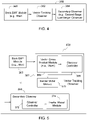
- FIG. 4 illustrates a block diagram of one embodiment of a position estimator (358 or 458) with a vector tracking observer 362 and a secondary observer 364.
- the estimator (358 or 458) (358 or 458) may incorporate or communicate with the back-EMF module 360 or a reference frame converter (e.g., an Inverse Park Transform) to convert between a rotating rotor d-q reference frame and a two-axis stationary reference frame (e.g., defined by V ⁇ and V ⁇ axes).
- the estimator (358 or 458) or electronic data processor 264 can derive the two-axis stationary reference frame directly from two or three phase voltage measurements or current measurements at the input to the machine (e.g., motor 117).
- the position/motion estimator (358 or 458) comprises a back-EMF module 360 coupled to or in communication with a vector-tracking observer.
- the vector tracking observer 362 is coupled to or communicates with a secondary observer 364.
- An estimator (358 or 458) or back-EMF module 360 is configured to estimate back-EMF vectors from the converted current vectors (e.g., via a current model, equations or a look-up tables).
- a vector tracking observer 362, a vector cross product module 366, or the electronic data processor 264 is adapted to mix (e.g., heterodyne or apply a vector cross product) the back-EMF vectors and to apply the mixed (e.g., heterodyned) back-EMF vectors to a preliminary inertial model managed by the inertial model module 370.
- a secondary observer 364 or the data processor 264 is operable to apply the output of the preliminary inertial model module 370 to a secondary inertial model of a secondary inertial model module 374 in the second speed range to estimate position or motion data for the rotor (e.g., a smoothed position of the rotor of the machine versus time, rotor velocity, or rotor acceleration).
- back-EMF tracking works on the principle that the back-EMF of the machine (e.g., motor 117) aligns with the q-axis in the synchronous d-q axis reference frame.
- the back-EMF magnitude and phase are known in the stationary reference frame, then the angular position is also known in the synchronous d-q frame.
- the back-EMF vector can be estimated using a state filter based stationary frame current observer.
- V ⁇ I ⁇ r s + pI ⁇ L s + E ⁇
- ⁇ e a back-electromotive force vector (associated with the ⁇ or ⁇ modeled phase of the stationary reference frame)
- ⁇ r is the angular rotor position
- V ⁇ is the complex voltage vector for the ⁇ and ⁇ components in the stationary reference frame
- I ⁇ is the complex current vector for the ⁇ and ⁇ components in the stationary reference frame
- r s is the stator resistance for one phase of the stator windings
- p is the differential operator
- L s is the stator inductance for one phase of windings
- ⁇ pm the flux linkage of the permanent magnets for the machine
- E ⁇ is a complex back-electromotive force
- V ⁇ k I ⁇ k * r s ⁇ L s T + I ⁇ k + 1 * L s T + E ⁇ k
- the back-EMF module 360 uses the above equation to implement, define or form a stationary frame state filter for back-EMF estimation based on stationary frame current observer in accordance with a discrete time model.
- the complex vector is decomposed into separate models for ⁇ and ⁇ scalar components. Because the back-EMF is not modeled, it is inherently estimated by the observer controller 368 within the bandwidth of the observer controller 368.
- the measured three phase currents are transformed into ⁇ and ⁇ components and is used as the tracking signal for the stationary frame current observer.
- the observer controller (368, 372) in this case is only a proportional gain.
- the observer controller (368, 372) provides the convergence dynamics for the estimated current in the presence of disturbance and parameter estimation errors.
- FIG. 5 illustrates a block diagram of another embodiment of a position estimator (358 or 458) featuring a vector cross product module 366, such as a mixer, a mixing module or a heterodyning module.
- the configuration of the position/motion estimator (358 or 458) of FIG. 5 is similar to the configuration of the position/motion estimator (358 or 458) of FIG. 4 , except FIG. 5 shows the vector tracking observer 362 and the secondary observer 364 in more detail.
- Like features, modules or elements in FIG. 4 and FIG. 5 are indicated by like reference numbers.
- H ⁇ is a filtering response vector for the ⁇ and ⁇ components in the stationary reference frame
- e j ⁇ e the composite real and imaginary filter response that is function of ⁇ e
- ⁇ e is the angular rotor position derived from back-EMF response.
- the vector-cross product module 366 or the mixer performs a vector cross product or vector dot product (scalar product) between the input to the vector tracking observer 362 and the estimated output from the observer vector tracking observer 362.
- the output after vector cross product of the observer input and estimated output of the observer will be the angular error ⁇ err which is passed to the standard or modified Luenberger observer.
- the vector tracking observer 362 which consists of the inertial model, observer controller 368 and command feedforward estimates the acceleration, instantaneous and average speeds, and rotor position.
- the instantaneous speed is fed to a secondary observer 364, such as a second stage Luenberger observer or modified Luenberger observer, for further filtering (lower bandwidth) of speed that could be used for closed loop speed control.
- a disturbance estimate from the secondary observer 364 is used to perform disturbance input decoupling to improve the dynamic stiffness of the closed loop motion controller
- a standard Luenberger Observer needs position as the outer state signal to estimate the inner states.
- the output of the back-EMF state filter could be directly used to determine the rotor position by using the arc-tangent function.
- the arc-tangent is a non-linear function and is sensitive to noise, hence the estimated position will be noisy.
- the estimator (358 or 458) avoids the arc-tangent operation for estimating rotor position (e.g., estimates illustrated in FIG. 7A ) by using the vector tracking observer 362, which further behaves like a zero-lag filter thus able to achieve cleaner position estimates and a lower accurate minimum speed for the second range.
- the raw estimated rotor position will be fed to a heterodyning Luenberger observer module which will estimate the rotor speed and position with zero lead/lag.
- the estimated position is used for field oriented control.
- a second stage Luenberger observer will be used to filter the noise from the speed estimated from the first stage, again with zero lead/lag.
- the filtered estimated speed is used for closed loop speed control.
- the estimated shaft torque will be used to perform disturbance input decoupling to improve the dynamic stiffness of the closed loop system.
- the vector cross product module 366 (e.g., heterodyning position tracking observer) can outperform the accuracy of a traditional, cascaded Luenberger observer with arc-tangent position determination (i.e., back EMF sliding mode observer followed by arc tangent determinations from EMF observer output), as is illustrated by comparing the rotor position estimates of FIG. 7A to FIG. 7B .
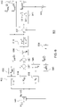
- FIG. 6 illustrates an illustrative discrete time model 600 for a vector tracking observer 362.
- the vector tracking of the back-EMF vectors facilitates tracking rotor position signals which output rotating vectors of two orthogonal signals.
- the block diagram of the vector tracking is shown in Figure 6 .
- a cross product module or mixer takes the vector cross product of the vector H ⁇ and feedback 613 from output 612 of the vector tracking observer 362 or the secondary observer 372 to produce an angular error ⁇ err .
- the feedback 613 is processed by amplifying, gain or attenuation in block 609 and averaging of rotor angle over one or more time periods in block 608.
- Block 603 represents a gain parameter K iso ;
- block 604 represents a gain parameter K SO ;
- block 605 represents a gain parameter b o .
- Block 606 represents a machine parameter value and T ⁇ em(Z) represents commanded torque for the machine or motor 117.
- the discrete time model is expressed as various Z-domain functions in blocks 602, 610, and 611 where Z represents a complex number that can indicate a frequency-domain response and where T represents a time period (e.g., related to the sampling frequency of current or voltage signals at the phase terminals of the machine or motor 117).
- the adding function is represented in circular blocks 607.
- the outputs 612 relate to time-averaged back-electromotive force vectors ( ⁇ rmL Z ⁇ and ⁇ rmR Z ⁇ ) (e.g., associated with the two-axis stationary reference frame) and the time-averaged rotor angular position ⁇ rm Z ⁇ .
- FIG. 7A illustrates a typical prior art arc tangent position estimation expressed a noisy saw-tooth waveform.
- the vertical axis 701 represents angular rotor position in electrical degrees
- the horizontal axis represents 702 time.
- the estimated or observed arc-tangent derived rotor position estimate 703 is shown in a solid line that is representative of a substantially triangular waveform.
- the ideal or actual angular rotor position 706 is illustrated as a dashed line that is representative of substantially triangular waveform.
- the derived rotor position estimate 703 varies about the actual angular rotor position because of noise associated with the observed arc-tangent derived rotor position estimate 703.
- Both the observed arc-tangent derived rotor position estimate 703 and the actual angular rotor position have a transition region or trailing edge 704 associated with a transition from a 360-degree angular position and a zero-degree angular position of the next rotation of the rotor.
- the variation, fluctuation or error in the respective waveforms for the arc-tangent derived rotor position estimate 703 and the derived rotor position estimate 707 is exaggerated for illustrative purposes and the actual variation, fluctuation or error may differ in practice in accordance with the applicable noise associated with the observed or measured phase signals of the input terminals of the machine (e.g., motor 117), among other factors.
- FIG. 7B illustrates a vector cross product or mixed (e.g., heterodyned) observer position estimation in accordance with this disclosure.
- the derived rotor position estimate 707 is based on the estimator (358 or 458), rather than the art-tangent derived method. Accordingly, the derived rotor position estimate 707 is associated with less noise as indicated by less variation in the solid line with respect to the actual angular rotor position 706.
- FIG. 8 is a flow chart of one embodiment of a method for controlling a permanent magnetic machine without a mechanical position sensor. The method of FIG. 8 begins in step S800.
- a state evaluator, estimator (358 or 458) or data processor 264 determines whether the machine is operating within a first speed range or a second speed range, where the second speed range is greater than the first speed range.
- a sensor is configured to sense current, or an equivalent voltage, of one or more output phases of an inverter, associated with back electromotive force (back EMF) of the machine.
- back EMF back electromotive force
- step S804 a back-EMF module 360, a converter or electronic data processor 264 is adapted to convert the derived or sensed current into current vectors associated with a stationary reference frame.
- a back-EMF module 360 an estimator (358 or 458) or an electronic data processor 264 is configured to estimate back-EMF vectors from the converted current vectors.
- the back-EMF module 360 comprises a back electromotive force filter module that filters the converted sensed current vectors to output filtered back EMF vectors.
- a vector tracking observer 362 or the electronic data processor 264 is adapted to mix (e.g., heterodyne or apply a vector cross product) the back-EMF vectors and applying the mixed (e.g., heterodyned) back-EMF vectors to a preliminary inertial model.
- the vector tracking observer 362 mixes or heterodynes the filtered sensed back-EMF vectors and an estimated initial current state output of the vector tracking observer 362 by taking a vector cross product of the filtered sensed back-EMF vectors and the estimated output of the vector tracking observer 362 to output a differential or final back-EMF state output (e.g., a cross-product indicative of error in the position).
- a secondary observer 364 or the data processor 264 is operable to apply the output of the preliminary inertial model to a secondary inertial model in the second speed range to estimate position or motion data for the rotor (e.g., a smoothed position of the rotor of the machine versus time, rotor velocity, or rotor acceleration).
- the vector tracking observer 362 applies the differential or final current state output to secondary observer 364, where the secondary observer 364 comprises a modified Luenberger observer that outputs a generally saw-tooth waveform indicative of the rotor position versus time, and where a noise level is less than a minimum threshold of signal-to-noise ratio of the saw-tooth waveform.
- the secondary observer 364 applies an inertial model to the differential or final current state to output a generally saw-tooth waveform indicative of the rotor position versus time, where a noise level is less than a minimum threshold of signal-to-noise ratio of the saw-tooth waveform.
- FIG. 9 is a flow chart of another embodiment of a method for controlling a permanent magnetic machine without a mechanical position sensor.
- the method of FIG. 9 is similar to the method of FIG. 8 except the method of FIG. 9 further includes the step S812.
- the pulse-width modulation generation module 112 or inverter switching circuit 188 applies a quadrature-axis voltage or quadrature-axis current (or commanded torque) to the machine to achieve a corresponding rotor speed based on machine parameters if the machine is operating within the first speed range.
- the machine parameters may comprise the machine inductance ( L s ) in the synchronous d-q reference frame (not the alpha-beta stationary reference frame), the resistance (R) per phase of the stator windings, and the flux linkage ( ⁇ PM ) of the permanent magnets (not between stator and the rotor).
- Step S812 may be carried out in accordance with various techniques for control of the machine in the first speed range, which may be applied separately or cumulatively.
- electronic data processing system supports a transition state in which a torque load on the machine less than a torque load threshold to effectuate a transition in which a rotational position of the rotor shaft is aligned based on a first position estimate associated with the first control mode (e.g., V/Hz in spec) and a second position estimate (e.g., in FOC or SVPWM with estimates based on position estimator (358 or 458) with vector tracking observer 362 and secondary observer 364) associated with the second control mode, the transition between the position between a first control mode in the first speed range and a second control mode in the second speed range.
- a first position estimate associated with the first control mode
- a second position estimate e.g., in FOC or SVPWM with estimates based on position estimator (358 or 458) with vector tracking observer 362 and secondary observer 36
- FIG. 10 is a flow chart of another embodiment of a method for controlling a permanent magnetic machine without a mechanical position sensor.
- the method of FIG. 10 is similar to the method of FIG. 8 except the method of FIG. 10 further includes the step S814.
- step S814 the pulse-width modulation generation module 112 or inverter switching circuit 188 applies a commanded voltage or current (or commanded torque) to the machine in accordance with a field-oriented control mode (e.g., space-vector-pulse-width modulation mode) to achieve a corresponding rotor speed if the machine is operating with the second speed range.
- a field-oriented control mode e.g., space-vector-pulse-width modulation mode
- the method may be carried out in accordance with various processes, which may be applied separately or cumulatively.
- the pulse width modulation generation module 112 or the inverter switching circuit 188 applies a commanded current or commanded voltage to the machine via the inverter switching module based on the sensed smoothed position of the rotor of the machine versus time or the smoothed, estimated rotor speed.
- the commended current or commanded current is consistent with a space-vector-pulse-width-modulation signal or field- oriented-control (FOC) command.
- FOC field- oriented-control
- electronic data processing system supports a transition state in which a torque load on the machine less than a torque load threshold to effectuate a transition in which a rotational position of the rotor shaft is aligned based on a first position estimate associated with the first control mode (e.g., V/Hz mode) and a second position estimate (e.g., in FOC or SVPWM) with estimates based on position estimator (358 or 458) with vector tracking observer 362 and secondary observer 364) associated with the second control mode, the transition between the position between a first control mode in the first speed range and a second control mode in the second speed range.
- a first position estimate associated with the first control mode e.g., V/Hz mode
- a second position estimate e.g., in FOC or SVPWM
Landscapes
- Engineering & Computer Science (AREA)
- Power Engineering (AREA)
- Control Of Ac Motors In General (AREA)
- Control Of Motors That Do Not Use Commutators (AREA)
Claims (15)
- Verfahren zur Steuerung einer Permanentmagnetmaschine, wobei das Verfahren aufweist:Bestimmen (S800), ob die Maschine innerhalb eines ersten Drehzahlbereichs oder eines zweiten Drehzahlbereichs betrieben wird, wobei der zweite Drehzahlbereich größer ist als der erste Drehzahlbereich;Erfassen (S802) von Strom von einer oder mehreren Ausgangsphasen des Wechselrichters, der mit einer gegenelektromotorischen Kraft der Maschine verbunden ist;Umwandeln (S804) des erfassten Stroms in mit einem stationären Referenzrahmen verbundene Stromvektoren;Schätzen (S806) von Vektoren der gegenelektromotorischen Kraft (EMK) anhand des umgewandelten erfassten Stroms zum Ableiten einer durchschnittlichen Rotorstellung über eine Abtastzeitspanne;in einem Vektorverfolgungsbeobachter Mischen (S808) eines Beobachterausgangs und eines Beobachtereingangs, wobei der Beobachterausgang die durchschnittliche Rotorstellung aufweist und wobei der Beobachtereingang eine von Gegen-EMK-Vektoren abgeleitete Rotorstellung ist, und Anwenden eines resultierenden Vektorprodukts oder eines Winkellagefehlers von dem Mischen auf ein vorläufiges Trägheitsmodell; gekennzeichnet durch,in einem sekundären Beobachter, Anwenden (S810) des Ausgangs des vorläufigen Trägheitsmodells auf ein sekundäres Trägheitsmodell in dem zweiten Drehzahlbereich zum Schätzen einer geglätteten Stellung des Rotors der Maschine gegenüber der Zeit oder einer geglätteten, geschätzten Rotordrehzahl.
- Verfahren nach Anspruch 1, das ferner aufweist:
Anwenden (S812) einer Spannung der Quadraturachse oder eines Stroms der Quadraturachse auf die Maschine, um eine entsprechende Rotordrehzahl auf Basis von Maschinenmotoren zu erzielen, wenn die Maschine innerhalb des ersten Drehzahlbereichs betrieben wird. - Verfahren nach Anspruch 2, wobei die Maschinenparameter die Maschineninduktanz, Ls, in dem synchronen d-q-Referenzrahmen, nicht dem stationären Alpha-Beta-Referenzrahmen, den Widerstand, R, pro Phase der Statorwicklung und die Flussverkettung, λPM, der Permanentmagneten nicht zwischen Stator und dem Rotor aufweisen.
- Verfahren nach Anspruch 1, wobei der/die angewendete Strom der Quadraturachse oder äquivalente Spannung der Quadraturachse in einem Spannungs-/Hertz-Steuermodus mit der folgenden Gleichung übereinstimmt:

- Verfahren nach Anspruch 1, das ferner aufweist:
Anwenden eines befohlenen Stroms oder einer befohlenen Spannung auf die Maschine über das Wechselrichterschaltmodul auf Basis der erfassten geglätteten Stellung des Rotors der Maschine gegenüber der Zeit oder der geglätteten geschätzten Rotordrehzahl. - Verfahren nach Anspruch 5, wobei der empfohlene Strom oder der befohlene Strom mit einem Raumzeiger-Pulsbreitenmodulation-Signal übereinstimmt.
- Verfahren nach Anspruch 1, das ferner aufweist:Filtern, durch das Filtermodul für die gegenelektromotorische Kraft, der umgewandelten erfassten Stromvektoren zum Ausgeben gefilterter Gegen-EMK-Vektoren;Anwenden des Vektorverfolgungsbeobachters zum Mischen oder Überlagern der gefilterten erfassten Gegen-EMK-Vektoren und eines geschätzten anfänglichen Stromzustandsausgangs eines Vektorverfolgungsbeobachters durch Nehmen eines Vektor-Kreuzprodukts der gefilterten erfassten Gegen-EMK-Vektoren und des geschätzten Ausgangs des Vektorverfolgungsbeobachters, um einen differentiellen oder endgültigen Gegen-EMK-Zustandsausgang auszugeben.
- Verfahren nach Anspruch 7, das ferner aufweist:
Anwenden des differentiellen oder endgültigen Stromzustandsausgangs an einen sekundären Beobachter. - Verfahren nach Anspruch 8, wobei der sekundäre Beobachter einen modifizierten Luenberger-Beobachter aufweist, der eine allgemein sägezahnförmige Wellenform ausgibt, die für die Rotorstellung gegenüber der Zeit bezeichnend ist, wobei ein Rauschpegel kleiner als ein Mindestschwellenwert des Signal-Rausch-Verhältnisses der Sägezahnwellenform ist.
- Verfahren nach Anspruch 8, wobei der sekundäre Beobachter ein Trägheitsmodell auf den differentiellen oder endgültigen Stromzustand anwendet, um eine allgemein sägezahnförmige Wellenform auszugeben, die für die Rotorstellung gegenüber der Zeit bezeichnend ist, wobei ein Rauschpegel kleiner als ein Mindestschwellenwert des Signal-Rausch-Verhältnisses der Sägezahnwellenform ist.
- Verfahren nach Anspruch 1, das ferner einen Übergangszustand aufweist, in dem eine Drehmomentbelastung der Maschine kleiner als ein Drehmomentbelastungsschwellenwert ist, um einen Übergang zu bewirken, bei dem eine Drehlage der Rotorwelle auf Basis einer mit dem ersten Steuermodus verbundenen ersten Stellungsschätzung und einer mit dem zweiten Steuermodus verbundenen zweiten Stellungsschätzung ausgerichtet wird, wobei der Übergang zwischen der Stellung zwischen einem ersten Steuermodus in dem ersten Drehzahlbereich und einem zweiten Steuermodus in dem zweiten Drehzahlbereich ist.
- System zum Steuern einer Permanentmagnetmaschine, wobei das System aufweist:einen Zustandsbewerter zum Ermitteln, ob die Maschine innerhalb eines ersten Drehzahlbereichs oder eines zweiten Drehzahlbereichs betrieben wird, wobei der zweite Drehzahlbereich größer als der erste Drehzahlbereich ist;mindestens einen Sensor zum Erfassen von Strom, von ein oder mehr Ausgangsphasen des Wechselrichters, der mit der gegenelektromotorischen Kraft der Maschine verbunden sind;einen Wandler zum Umwandeln des erfassten Stroms in Stromvektoren, die mit einem stationären Referenzrahmen verbunden sind;ein Gegenelektromotorische-Kraft-Modul zum Schätzen von Vektoren der gegenelektromotorischen Kraft (EMK) anhand des umgewandelten erfassten Stroms zum Ableiten einer durchschnittlichen Rotorstellung über eine Abtastzeitspanne;einen Vektorverfolgungsbeobachter, der einen elektronischen Datenprozessor oder einen Mischer aufweist, der zum Mischen eines Beobachterausgangs und eines Beobachtereingangs konfiguriert ist, wobei der Beobachterausgang die durchschnittliche Rotorstellung aufweist und wobei der Beobachtereingang eine von Gegen-EMK-Vektoren abgeleitete Rotorstellung ist, und ferner zum Anwenden eines resultierenden Vektorprodukts oder eines Winkellagefehlers von dem Mischen auf ein vorläufiges Trägheitsmodell konfiguriert ist; gekennzeichnet durcheinen sekundären Beobachter oder den elektronischen Datenprozessor, der zum Anwenden des Ausgangs des vorläufigen Trägheitsmodells auf ein sekundäres Trägheitsmodell in dem zweiten Drehzahlbereich zum Schätzen einer geglätteten Stellung des Rotors der Maschine gegenüber der Zeit oder einer geglätteten, geschätzten Rotordrehzahl konfiguriert ist.
- System nach Anspruch 12, das ferner aufweist:
ein erstes Modussteuermodul oder den elektronischen Datenprozessor zum Anwenden einer Spannung der Quadraturachse oder eines Stroms der Quadraturachse auf die Maschine, um eine entsprechende Rotordrehzahl auf Basis von Maschinenparametern zu erzielen, falls die Maschine innerhalb des ersten Drehzahlbereichs betrieben wird. - System nach Anspruch 13, wobei die Maschinenparameter die Maschineninduktanz, Ls, im synchronen d-q-Referenzrahmen, den Widerstand, R, pro Phase der Statorwicklung und die Flussverkettung, λPM, der Permanentmagneten aufweisen.
- System nach Anspruch 13, wobei der/die angewendete Strom der Quadraturachse oder äquivalente Spannung der Quadraturachse in einem Spannungs-/Hertz-Steuermodus mit der folgenden Gleichung übereinstimmt:

Applications Claiming Priority (2)
| Application Number | Priority Date | Filing Date | Title |
|---|---|---|---|
| US201962812368P | 2019-03-01 | 2019-03-01 | |
| US16/598,664 US11233473B2 (en) | 2019-03-01 | 2019-10-10 | Method and system for controlling a permanent magnet machine without a mechanical position sensor |
Publications (2)
| Publication Number | Publication Date |
|---|---|
| EP3703245A1 EP3703245A1 (de) | 2020-09-02 |
| EP3703245B1 true EP3703245B1 (de) | 2022-06-08 |
Family
ID=69591571
Family Applications (1)
| Application Number | Title | Priority Date | Filing Date |
|---|---|---|---|
| EP20157258.3A Active EP3703245B1 (de) | 2019-03-01 | 2020-02-13 | Verfahren und system zur steuerung einer permanentmagnetmaschine ohne einen mechanischen positionssensor |
Country Status (2)
| Country | Link |
|---|---|
| US (1) | US11233473B2 (de) |
| EP (1) | EP3703245B1 (de) |
Families Citing this family (17)
| Publication number | Priority date | Publication date | Assignee | Title |
|---|---|---|---|---|
| US11987132B2 (en) * | 2021-01-11 | 2024-05-21 | GM Global Technology Operations LLC | Linear time varying model predictive torque control |
| CN113965128B (zh) * | 2021-06-07 | 2024-10-15 | 深圳市维京驱动有限公司 | 一种永磁电机一体式驱动、检测系统及方法 |
| CN114465537B (zh) * | 2021-12-07 | 2024-02-27 | 北京国家新能源汽车技术创新中心有限公司 | 永磁同步电机高精度建模方法、设备及存储介质 |
| CN114337402B (zh) * | 2021-12-08 | 2023-09-22 | 燕山大学 | 一种同步磁阻电机电感参数辨识及转子位置混合估计方法 |
| CN114499324B (zh) * | 2022-01-17 | 2024-05-28 | 北京理工大学 | 一种基于位置传感器的pmsm三闭环矢量控制装置及方法 |
| US12348161B2 (en) | 2022-01-28 | 2025-07-01 | Tau Motors, Inc. | Motor control using piecewise affine model |
| CN114826054B (zh) * | 2022-03-01 | 2024-08-02 | 南京溧水电子研究所有限公司 | 电机控制方法 |
| CN114865977B (zh) * | 2022-06-08 | 2025-03-14 | 浙江大学先进电气装备创新中心 | 一种适用于双轴永磁伺服系统的非线性预测位置控制方法 |
| CN115425891B (zh) * | 2022-10-14 | 2025-04-11 | 哈尔滨理工大学 | 永磁开关磁链电机无位置传感器直接转矩控制系统及控制方法 |
| DE102022214075A1 (de) | 2022-12-20 | 2024-06-20 | Robert Bosch Gesellschaft mit beschränkter Haftung | Elektrische Maschine mit einer drehzahlabhängigen Rotorpositionserfassung |
| CN116317765B (zh) * | 2023-04-20 | 2025-08-01 | 西安理工大学 | 提高永磁同步电机无传感器控制观测精度的方法及相关装置 |
| KR20260046084A (ko) * | 2023-06-15 | 2026-04-06 | 타우 모터스, 인크. | 최적 효율 레퍼런스 생성을 이용한 모터 제어 |
| CN116599413B (zh) * | 2023-07-17 | 2023-09-22 | 南京信息工程大学 | 一种永磁同步电机的无位置传感器控制方法及装置 |
| WO2025122562A2 (en) * | 2023-12-05 | 2025-06-12 | Magna International Inc. | System and method for hybrid control of pmsm drive using two current sensors |
| CN118523678B (zh) * | 2024-05-13 | 2025-01-24 | 湖南大学 | 一种考虑交叉耦合电感的电机控制方法及系统 |
| CN118508514B (zh) * | 2024-07-22 | 2024-09-27 | 国网江苏省电力有限公司电力科学研究院 | 一种柴储联合发电系统及储能充电控制方法 |
| CN119891843B (zh) * | 2025-03-28 | 2025-07-15 | 中山格智美电器有限公司 | 一种永磁同步电机的控制方法 |
Family Cites Families (8)
| Publication number | Priority date | Publication date | Assignee | Title |
|---|---|---|---|---|
| US5585709A (en) * | 1993-12-22 | 1996-12-17 | Wisconsin Alumni Research Foundation | Method and apparatus for transducerless position and velocity estimation in drives for AC machines |
| US6894454B2 (en) * | 2002-10-10 | 2005-05-17 | General Motors Corporation | Position sensorless control algorithm for AC machine |
| US7495404B2 (en) | 2005-08-17 | 2009-02-24 | Honeywell International Inc. | Power factor control for floating frame controller for sensorless control of synchronous machines |
| US9548686B2 (en) * | 2013-05-03 | 2017-01-17 | Texas Instruments Incorporated | Angle/frequency selector in an electric motor controller architecture |
| JP2015080344A (ja) | 2013-10-17 | 2015-04-23 | 株式会社荏原製作所 | 電動機の駆動装置 |
| US10171019B1 (en) | 2017-06-29 | 2019-01-01 | Toshiba Mitsubishi-Electric Industrial Systems Corporation | Controller for power converter |
| CN108880377A (zh) * | 2018-06-20 | 2018-11-23 | 泉州装备制造研究所 | 一种基于新型锁相环的永磁同步电机的转速估计方法 |
| US10797629B2 (en) * | 2018-11-23 | 2020-10-06 | Texas Instruments Incorporated | Low speed sensorless rotor angle estimation |
-
2019
- 2019-10-10 US US16/598,664 patent/US11233473B2/en active Active
-
2020
- 2020-02-13 EP EP20157258.3A patent/EP3703245B1/de active Active
Also Published As
| Publication number | Publication date |
|---|---|
| US20200280276A1 (en) | 2020-09-03 |
| EP3703245A1 (de) | 2020-09-02 |
| US11233473B2 (en) | 2022-01-25 |
Similar Documents
| Publication | Publication Date | Title |
|---|---|---|
| EP3703245B1 (de) | Verfahren und system zur steuerung einer permanentmagnetmaschine ohne einen mechanischen positionssensor | |
| US8853979B2 (en) | Method and system for calibrating rotor position offset of an electric motor | |
| US8810169B2 (en) | Method and system for estimating rotor angle of an electric machine | |
| US6002234A (en) | System and method for controlling brushless permanent magnet motors | |
| EP2889999B1 (de) | Verfahren zur Drehmomentschätzung und -kompensation sowie Systeme dafür | |
| US8648555B2 (en) | Method and system for controlling an electric motor at or near stall conditions | |
| JP3411878B2 (ja) | 同期モータの回転子位置推定方法、位置センサレス制御方法及び制御装置 | |
| EP2678939B1 (de) | Verfahren und system zur steuerung eines elektromotors mit temperaturkompensation | |
| CN103051277B (zh) | 用于永磁同步电动机驱动系统的参数估计装置 | |
| US9071186B2 (en) | Method and apparatus for controlling an alternating current machine | |
| US20040007995A1 (en) | Vector control system for permanent magnet sychronous machines using an open-loop parameter observer | |
| US8723460B2 (en) | Method and system for controlling an electric motor with compensation for time delay in position determination | |
| CN102224672A (zh) | 用于高效能无铁心永磁电机的无传感器最优转矩控制 | |
| EP4152593B1 (de) | System und verfahren eines robusten anlauf- und auslaufschemas zur lagesensorlosen steuerung einer elektrischen maschine | |
| Bist et al. | Sensorless control based on sliding mode observer for pmsm drive | |
| Nishad et al. | Induction motor control using modified indirect field oriented control | |
| US9154070B2 (en) | Controller for AC motor | |
| US6777906B1 (en) | Method of controlling induction motor | |
| EP1681762B1 (de) | Synchronmotorantriebssystem und Verfahren | |
| US20250105770A1 (en) | Device and method for controlling a synchronous machine and for estimating rotor position, from start-up to a predetermined low speed | |
| US20240372494A1 (en) | Method for Controlling a Three-Phase Electric Machine and Control Unit and System Thereof | |
| US20240014757A1 (en) | Method and device for controlling three-phase motor | |
| CN115242141A (zh) | 电机的功率控制方法及控制装置、计算机存储介质 | |
| KR20240048351A (ko) | Ac 모터의 센서리스 구동 장치 및 방법 |
Legal Events
| Date | Code | Title | Description |
|---|---|---|---|
| PUAI | Public reference made under article 153(3) epc to a published international application that has entered the european phase |
Free format text: ORIGINAL CODE: 0009012 |
|
| STAA | Information on the status of an ep patent application or granted ep patent |
Free format text: STATUS: THE APPLICATION HAS BEEN PUBLISHED |
|
| AK | Designated contracting states |
Kind code of ref document: A1 Designated state(s): AL AT BE BG CH CY CZ DE DK EE ES FI FR GB GR HR HU IE IS IT LI LT LU LV MC MK MT NL NO PL PT RO RS SE SI SK SM TR |
|
| AX | Request for extension of the european patent |
Extension state: BA ME |
|
| STAA | Information on the status of an ep patent application or granted ep patent |
Free format text: STATUS: REQUEST FOR EXAMINATION WAS MADE |
|
| 17P | Request for examination filed |
Effective date: 20210302 |
|
| RBV | Designated contracting states (corrected) |
Designated state(s): AL AT BE BG CH CY CZ DE DK EE ES FI FR GB GR HR HU IE IS IT LI LT LU LV MC MK MT NL NO PL PT RO RS SE SI SK SM TR |
|
| GRAP | Despatch of communication of intention to grant a patent |
Free format text: ORIGINAL CODE: EPIDOSNIGR1 |
|
| STAA | Information on the status of an ep patent application or granted ep patent |
Free format text: STATUS: GRANT OF PATENT IS INTENDED |
|
| INTG | Intention to grant announced |
Effective date: 20220217 |
|
| GRAS | Grant fee paid |
Free format text: ORIGINAL CODE: EPIDOSNIGR3 |
|
| GRAA | (expected) grant |
Free format text: ORIGINAL CODE: 0009210 |
|
| STAA | Information on the status of an ep patent application or granted ep patent |
Free format text: STATUS: THE PATENT HAS BEEN GRANTED |
|
| AK | Designated contracting states |
Kind code of ref document: B1 Designated state(s): AL AT BE BG CH CY CZ DE DK EE ES FI FR GB GR HR HU IE IS IT LI LT LU LV MC MK MT NL NO PL PT RO RS SE SI SK SM TR |
|
| REG | Reference to a national code |
Ref country code: AT Ref legal event code: REF Ref document number: 1497614 Country of ref document: AT Kind code of ref document: T Effective date: 20220615 Ref country code: CH Ref legal event code: EP |
|
| REG | Reference to a national code |
Ref country code: DE Ref legal event code: R096 Ref document number: 602020003412 Country of ref document: DE |
|
| REG | Reference to a national code |
Ref country code: IE Ref legal event code: FG4D |
|
| REG | Reference to a national code |
Ref country code: LT Ref legal event code: MG9D |
|
| REG | Reference to a national code |
Ref country code: NL Ref legal event code: MP Effective date: 20220608 |
|
| PG25 | Lapsed in a contracting state [announced via postgrant information from national office to epo] |
Ref country code: SE Free format text: LAPSE BECAUSE OF FAILURE TO SUBMIT A TRANSLATION OF THE DESCRIPTION OR TO PAY THE FEE WITHIN THE PRESCRIBED TIME-LIMIT Effective date: 20220608 Ref country code: NO Free format text: LAPSE BECAUSE OF FAILURE TO SUBMIT A TRANSLATION OF THE DESCRIPTION OR TO PAY THE FEE WITHIN THE PRESCRIBED TIME-LIMIT Effective date: 20220908 Ref country code: LT Free format text: LAPSE BECAUSE OF FAILURE TO SUBMIT A TRANSLATION OF THE DESCRIPTION OR TO PAY THE FEE WITHIN THE PRESCRIBED TIME-LIMIT Effective date: 20220608 Ref country code: HR Free format text: LAPSE BECAUSE OF FAILURE TO SUBMIT A TRANSLATION OF THE DESCRIPTION OR TO PAY THE FEE WITHIN THE PRESCRIBED TIME-LIMIT Effective date: 20220608 Ref country code: GR Free format text: LAPSE BECAUSE OF FAILURE TO SUBMIT A TRANSLATION OF THE DESCRIPTION OR TO PAY THE FEE WITHIN THE PRESCRIBED TIME-LIMIT Effective date: 20220909 Ref country code: FI Free format text: LAPSE BECAUSE OF FAILURE TO SUBMIT A TRANSLATION OF THE DESCRIPTION OR TO PAY THE FEE WITHIN THE PRESCRIBED TIME-LIMIT Effective date: 20220608 Ref country code: ES Free format text: LAPSE BECAUSE OF FAILURE TO SUBMIT A TRANSLATION OF THE DESCRIPTION OR TO PAY THE FEE WITHIN THE PRESCRIBED TIME-LIMIT Effective date: 20220608 Ref country code: BG Free format text: LAPSE BECAUSE OF FAILURE TO SUBMIT A TRANSLATION OF THE DESCRIPTION OR TO PAY THE FEE WITHIN THE PRESCRIBED TIME-LIMIT Effective date: 20220908 |
|
| REG | Reference to a national code |
Ref country code: AT Ref legal event code: MK05 Ref document number: 1497614 Country of ref document: AT Kind code of ref document: T Effective date: 20220608 |
|
| PG25 | Lapsed in a contracting state [announced via postgrant information from national office to epo] |
Ref country code: RS Free format text: LAPSE BECAUSE OF FAILURE TO SUBMIT A TRANSLATION OF THE DESCRIPTION OR TO PAY THE FEE WITHIN THE PRESCRIBED TIME-LIMIT Effective date: 20220608 Ref country code: LV Free format text: LAPSE BECAUSE OF FAILURE TO SUBMIT A TRANSLATION OF THE DESCRIPTION OR TO PAY THE FEE WITHIN THE PRESCRIBED TIME-LIMIT Effective date: 20220608 |
|
| PG25 | Lapsed in a contracting state [announced via postgrant information from national office to epo] |
Ref country code: NL Free format text: LAPSE BECAUSE OF FAILURE TO SUBMIT A TRANSLATION OF THE DESCRIPTION OR TO PAY THE FEE WITHIN THE PRESCRIBED TIME-LIMIT Effective date: 20220608 |
|
| PG25 | Lapsed in a contracting state [announced via postgrant information from national office to epo] |
Ref country code: SM Free format text: LAPSE BECAUSE OF FAILURE TO SUBMIT A TRANSLATION OF THE DESCRIPTION OR TO PAY THE FEE WITHIN THE PRESCRIBED TIME-LIMIT Effective date: 20220608 Ref country code: SK Free format text: LAPSE BECAUSE OF FAILURE TO SUBMIT A TRANSLATION OF THE DESCRIPTION OR TO PAY THE FEE WITHIN THE PRESCRIBED TIME-LIMIT Effective date: 20220608 Ref country code: RO Free format text: LAPSE BECAUSE OF FAILURE TO SUBMIT A TRANSLATION OF THE DESCRIPTION OR TO PAY THE FEE WITHIN THE PRESCRIBED TIME-LIMIT Effective date: 20220608 Ref country code: PT Free format text: LAPSE BECAUSE OF FAILURE TO SUBMIT A TRANSLATION OF THE DESCRIPTION OR TO PAY THE FEE WITHIN THE PRESCRIBED TIME-LIMIT Effective date: 20221010 Ref country code: EE Free format text: LAPSE BECAUSE OF FAILURE TO SUBMIT A TRANSLATION OF THE DESCRIPTION OR TO PAY THE FEE WITHIN THE PRESCRIBED TIME-LIMIT Effective date: 20220608 Ref country code: CZ Free format text: LAPSE BECAUSE OF FAILURE TO SUBMIT A TRANSLATION OF THE DESCRIPTION OR TO PAY THE FEE WITHIN THE PRESCRIBED TIME-LIMIT Effective date: 20220608 Ref country code: AT Free format text: LAPSE BECAUSE OF FAILURE TO SUBMIT A TRANSLATION OF THE DESCRIPTION OR TO PAY THE FEE WITHIN THE PRESCRIBED TIME-LIMIT Effective date: 20220608 |
|
| PG25 | Lapsed in a contracting state [announced via postgrant information from national office to epo] |
Ref country code: PL Free format text: LAPSE BECAUSE OF FAILURE TO SUBMIT A TRANSLATION OF THE DESCRIPTION OR TO PAY THE FEE WITHIN THE PRESCRIBED TIME-LIMIT Effective date: 20220608 Ref country code: IS Free format text: LAPSE BECAUSE OF FAILURE TO SUBMIT A TRANSLATION OF THE DESCRIPTION OR TO PAY THE FEE WITHIN THE PRESCRIBED TIME-LIMIT Effective date: 20221008 |
|
| REG | Reference to a national code |
Ref country code: DE Ref legal event code: R097 Ref document number: 602020003412 Country of ref document: DE |
|
| PG25 | Lapsed in a contracting state [announced via postgrant information from national office to epo] |
Ref country code: AL Free format text: LAPSE BECAUSE OF FAILURE TO SUBMIT A TRANSLATION OF THE DESCRIPTION OR TO PAY THE FEE WITHIN THE PRESCRIBED TIME-LIMIT Effective date: 20220608 |
|
| PLBE | No opposition filed within time limit |
Free format text: ORIGINAL CODE: 0009261 |
|
| STAA | Information on the status of an ep patent application or granted ep patent |
Free format text: STATUS: NO OPPOSITION FILED WITHIN TIME LIMIT |
|
| PG25 | Lapsed in a contracting state [announced via postgrant information from national office to epo] |
Ref country code: DK Free format text: LAPSE BECAUSE OF FAILURE TO SUBMIT A TRANSLATION OF THE DESCRIPTION OR TO PAY THE FEE WITHIN THE PRESCRIBED TIME-LIMIT Effective date: 20220608 |
|
| 26N | No opposition filed |
Effective date: 20230310 |
|
| PG25 | Lapsed in a contracting state [announced via postgrant information from national office to epo] |
Ref country code: SI Free format text: LAPSE BECAUSE OF FAILURE TO SUBMIT A TRANSLATION OF THE DESCRIPTION OR TO PAY THE FEE WITHIN THE PRESCRIBED TIME-LIMIT Effective date: 20220608 |
|
| PG25 | Lapsed in a contracting state [announced via postgrant information from national office to epo] |
Ref country code: MC Free format text: LAPSE BECAUSE OF FAILURE TO SUBMIT A TRANSLATION OF THE DESCRIPTION OR TO PAY THE FEE WITHIN THE PRESCRIBED TIME-LIMIT Effective date: 20220608 |
|
| REG | Reference to a national code |
Ref country code: CH Ref legal event code: PL |
|
| REG | Reference to a national code |
Ref country code: BE Ref legal event code: MM Effective date: 20230228 |
|
| PG25 | Lapsed in a contracting state [announced via postgrant information from national office to epo] |
Ref country code: LU Free format text: LAPSE BECAUSE OF NON-PAYMENT OF DUE FEES Effective date: 20230213 Ref country code: LI Free format text: LAPSE BECAUSE OF NON-PAYMENT OF DUE FEES Effective date: 20230228 Ref country code: CH Free format text: LAPSE BECAUSE OF NON-PAYMENT OF DUE FEES Effective date: 20230228 |
|
| REG | Reference to a national code |
Ref country code: IE Ref legal event code: MM4A |
|
| PG25 | Lapsed in a contracting state [announced via postgrant information from national office to epo] |
Ref country code: IT Free format text: LAPSE BECAUSE OF FAILURE TO SUBMIT A TRANSLATION OF THE DESCRIPTION OR TO PAY THE FEE WITHIN THE PRESCRIBED TIME-LIMIT Effective date: 20220608 Ref country code: IE Free format text: LAPSE BECAUSE OF NON-PAYMENT OF DUE FEES Effective date: 20230213 |
|
| PG25 | Lapsed in a contracting state [announced via postgrant information from national office to epo] |
Ref country code: BE Free format text: LAPSE BECAUSE OF NON-PAYMENT OF DUE FEES Effective date: 20230228 |
|
| PG25 | Lapsed in a contracting state [announced via postgrant information from national office to epo] |
Ref country code: BG Free format text: LAPSE BECAUSE OF FAILURE TO SUBMIT A TRANSLATION OF THE DESCRIPTION OR TO PAY THE FEE WITHIN THE PRESCRIBED TIME-LIMIT Effective date: 20220608 |
|
| PG25 | Lapsed in a contracting state [announced via postgrant information from national office to epo] |
Ref country code: BG Free format text: LAPSE BECAUSE OF FAILURE TO SUBMIT A TRANSLATION OF THE DESCRIPTION OR TO PAY THE FEE WITHIN THE PRESCRIBED TIME-LIMIT Effective date: 20220608 |
|
| PG25 | Lapsed in a contracting state [announced via postgrant information from national office to epo] |
Ref country code: CY Free format text: LAPSE BECAUSE OF FAILURE TO SUBMIT A TRANSLATION OF THE DESCRIPTION OR TO PAY THE FEE WITHIN THE PRESCRIBED TIME-LIMIT; INVALID AB INITIO Effective date: 20200213 |
|
| PG25 | Lapsed in a contracting state [announced via postgrant information from national office to epo] |
Ref country code: HU Free format text: LAPSE BECAUSE OF FAILURE TO SUBMIT A TRANSLATION OF THE DESCRIPTION OR TO PAY THE FEE WITHIN THE PRESCRIBED TIME-LIMIT; INVALID AB INITIO Effective date: 20200213 |
|
| PG25 | Lapsed in a contracting state [announced via postgrant information from national office to epo] |
Ref country code: TR Free format text: LAPSE BECAUSE OF FAILURE TO SUBMIT A TRANSLATION OF THE DESCRIPTION OR TO PAY THE FEE WITHIN THE PRESCRIBED TIME-LIMIT Effective date: 20220608 |
|
| PGFP | Annual fee paid to national office [announced via postgrant information from national office to epo] |
Ref country code: GB Payment date: 20260227 Year of fee payment: 7 |
|
| PGFP | Annual fee paid to national office [announced via postgrant information from national office to epo] |
Ref country code: DE Payment date: 20260121 Year of fee payment: 7 |
|
| PGFP | Annual fee paid to national office [announced via postgrant information from national office to epo] |
Ref country code: FR Payment date: 20260225 Year of fee payment: 7 |