EP3704347B1 - Sicherer zündkopf für abgewandte bohrlöcher - Google Patents
Sicherer zündkopf für abgewandte bohrlöcher Download PDFInfo
- Publication number
- EP3704347B1 EP3704347B1 EP17808641.9A EP17808641A EP3704347B1 EP 3704347 B1 EP3704347 B1 EP 3704347B1 EP 17808641 A EP17808641 A EP 17808641A EP 3704347 B1 EP3704347 B1 EP 3704347B1
- Authority
- EP
- European Patent Office
- Prior art keywords
- stopper
- housing
- groove
- further characterized
- firing head
- Prior art date
- Legal status (The legal status is an assumption and is not a legal conclusion. Google has not performed a legal analysis and makes no representation as to the accuracy of the status listed.)
- Not-in-force
Links
- 238000010304 firing Methods 0.000 title claims description 68
- 230000005484 gravity Effects 0.000 claims description 26
- 239000003999 initiator Substances 0.000 claims description 25
- 238000000034 method Methods 0.000 claims description 9
- 230000003213 activating effect Effects 0.000 claims description 6
- 238000005096 rolling process Methods 0.000 claims 2
- 238000005474 detonation Methods 0.000 description 8
- 238000009527 percussion Methods 0.000 description 8
- 230000015572 biosynthetic process Effects 0.000 description 5
- 230000033001 locomotion Effects 0.000 description 4
- 239000004215 Carbon black (E152) Substances 0.000 description 3
- 229930195733 hydrocarbon Natural products 0.000 description 3
- 150000002430 hydrocarbons Chemical class 0.000 description 3
- XTFIVUDBNACUBN-UHFFFAOYSA-N 1,3,5-trinitro-1,3,5-triazinane Chemical compound [O-][N+](=O)N1CN([N+]([O-])=O)CN([N+]([O-])=O)C1 XTFIVUDBNACUBN-UHFFFAOYSA-N 0.000 description 2
- 238000004891 communication Methods 0.000 description 2
- 230000000694 effects Effects 0.000 description 2
- 239000012530 fluid Substances 0.000 description 2
- 239000000463 material Substances 0.000 description 2
- 238000012986 modification Methods 0.000 description 2
- 230000004048 modification Effects 0.000 description 2
- UZGLIIJVICEWHF-UHFFFAOYSA-N octogen Chemical compound [O-][N+](=O)N1CN([N+]([O-])=O)CN([N+]([O-])=O)CN([N+]([O-])=O)C1 UZGLIIJVICEWHF-UHFFFAOYSA-N 0.000 description 2
- 239000003129 oil well Substances 0.000 description 2
- 101100181504 Mus musculus Clc gene Proteins 0.000 description 1
- 230000001154 acute effect Effects 0.000 description 1
- 230000004888 barrier function Effects 0.000 description 1
- 230000005540 biological transmission Effects 0.000 description 1
- 239000000919 ceramic Substances 0.000 description 1
- 230000000295 complement effect Effects 0.000 description 1
- 238000010276 construction Methods 0.000 description 1
- 238000004880 explosion Methods 0.000 description 1
- 239000002360 explosive Substances 0.000 description 1
- 230000002706 hydrostatic effect Effects 0.000 description 1
- 239000002184 metal Substances 0.000 description 1
- 230000010399 physical interaction Effects 0.000 description 1
- 229920000642 polymer Polymers 0.000 description 1
- 238000011084 recovery Methods 0.000 description 1
- 239000011435 rock Substances 0.000 description 1
- 230000008054 signal transmission Effects 0.000 description 1
- 239000007787 solid Substances 0.000 description 1
Images



Classifications
-
- E—FIXED CONSTRUCTIONS
- E21—EARTH OR ROCK DRILLING; MINING
- E21B—EARTH OR ROCK DRILLING; OBTAINING OIL, GAS, WATER, SOLUBLE OR MELTABLE MATERIALS OR A SLURRY OF MINERALS FROM WELLS
- E21B43/00—Methods or apparatus for obtaining oil, gas, water, soluble or meltable materials or a slurry of minerals from wells
- E21B43/11—Perforators; Permeators
- E21B43/116—Gun or shaped-charge perforators
- E21B43/1185—Ignition systems
-
- E—FIXED CONSTRUCTIONS
- E21—EARTH OR ROCK DRILLING; MINING
- E21B—EARTH OR ROCK DRILLING; OBTAINING OIL, GAS, WATER, SOLUBLE OR MELTABLE MATERIALS OR A SLURRY OF MINERALS FROM WELLS
- E21B43/00—Methods or apparatus for obtaining oil, gas, water, soluble or meltable materials or a slurry of minerals from wells
- E21B43/11—Perforators; Permeators
- E21B43/116—Gun or shaped-charge perforators
- E21B43/1185—Ignition systems
- E21B43/11855—Ignition systems mechanically actuated, e.g. by movement of a wireline or a drop-bar
-
- F—MECHANICAL ENGINEERING; LIGHTING; HEATING; WEAPONS; BLASTING
- F42—AMMUNITION; BLASTING
- F42C—AMMUNITION FUZES; ARMING OR SAFETY MEANS THEREFOR
- F42C15/00—Arming-means in fuzes; Safety means for preventing premature detonation of fuzes or charges
- F42C15/34—Arming-means in fuzes; Safety means for preventing premature detonation of fuzes or charges wherein the safety or arming action is effected by a blocking-member in the pyrotechnic or explosive train between primer and main charge
Definitions
- the present disclosure relates to firing heads for actuating downhole tools.
- perforations such as passages or holes
- perforations are formed in the casing of the well to enable fluid communication between the wellbore and the hydrocarbon producing formation that is intersected by the well.
- These perforations are usually made with a perforating gun loaded with shaped charges.
- the gun is lowered into the wellbore on electric wireline, slickline or coiled tubing, or other means until it is at a desired target depth; e.g ., adjacent to a hydrocarbon producing formation.
- a surface signal actuates a firing head associated with the perforating gun, which then detonates the shaped charges. Projectiles or jets formed by the explosion of the shaped charges penetrate the casing to thereby allow formation fluids to flow from the formation through the perforations and into the production string for flowing to the surface.
- the firing head may include a housing, a pin, and a moveable stopper.
- the housing may have a bore and a radially enlarged chamber formed along the bore.
- the pin is disposed in the bore and has a circumferential groove formed on an outer surface of the shank.
- the moveable stopper is disposed in the radially enlarged chamber. The stopper is only partially disposed in the groove when the housing is in a vertical position. The stopper moves out of the groove when the housing has a predetermined minimum angular deviation from the vertical position.
- the present disclosure provides a method for selectively activating an initiator of a downhole tool using the above-described firing head.
- the method may include forming a downhole tool by positioning the firing head adjacent to the initiator; conveying the downhole tool into a wellbore, wherein the stopper prevents the pin from contacting the initiator unless the predetermined angular deviation is present; positioning the downhole tool at a desired location where the predetermined angular deviation is present; and activating the initiator using the firing head.
- the present disclosure relates to a firing head for detonating downhole tools.
- the present disclosure is susceptible to embodiments of different forms. There are shown in the drawings, and herein will be described in detail, specific embodiments of the present disclosure with the understanding that the present disclosure is to be considered an exemplification of the principles of the disclosure, and is not intended to limit the disclosure to that illustrated and described herein.
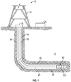
- the facility 10 can include known equipment and structures such as a rig 16, a wellhead 18, and cased or uncased pipe/tubing 20.
- a work string 22 is suspended within the wellbore 14 from the rig 16.
- the work string 22 can include drill pipe, jointed tubing, coiled tubing, wire line, slick line, or any other known conveyance means.
- the work string 22 can include telemetry lines or other signal/power transmission mediums that establish one-way or two-way telemetric communication.
- a telemetry system may have a surface controller (e.g., a power source) 24 adapted to transmit electrical signals via a cable or signal transmission line 26 disposed in the work string 22.
- a surface controller e.g., a power source
- the work string 22 may include a downhole tool 50 that is activated by a firing head 100.
- the downhole tool 50 is conveyed by the work string 22 along the various sections of the wellbore 14 until a desired target depth is reached.
- the wellbore 14 may have a complex geometry that includes one or more vertical sections 30 and one or more deviated sections 32. While shown as perfectly vertical and perfectly horizontal, the vertical sections 30 and the deviated sections 32 may vary in actual angular offset from a vertical datum, which is in the direction of gravity. In some instances, the target depth is in the deviated section 32 of the wellbore 14.
- firing heads according to the present disclosure are only operable after the downhole tool 50 is at a desired deviated orientation; e.g., horizontal.
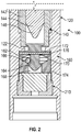
- the firing head 100 may include an outer housing 120, a percussion assembly 140, a pin assembly 160, and an initiator 210.
- the percussion assembly 140, the pin assembly 160, and the initiator 210 are serially, or an "end-to-end" arrangement, disposed in a bore 122 of the outer housing 120.
- the serial arrangement enables the transfer of kinetic energy that is used to impact and detonate the initiator 210, which may include one or more high-explosives, such as RDX (Hexogen, Cyclotrimethylenetrinltramine), HMX (Octagon, Cyclotetramethylenetetranitramine), CLCP, HNS, and PYX.
- the percussion assembly 140 uses an impact to transfer kinetic energy to the pin assembly 160.
- the percussion assembly 140 may include a sleeve or tube 142 that receives a sliding contact member 144.
- the contact member 144 may be shaped as a solid cylinder with a blunt nose 146 and an opposing end (not shown). Application of force to the opposing end (not shown) drives the contact member 144 toward the pin assembly 160.
- the force may be applied by a hydrostatic pressure in the wellbore, by an impact from a projectile, or a detonation.
- the pin assembly 160 selectively blocks the transfer of kinetic energy to the initiator 210 if a desired deviated orientation is not present.
- the stopper 166 prevents the pin assembly 160 from contacting the initiator 210, then the firing head 100 is in the "safe" position / condition.
- the pin assembly 160 may include a housing 162, a firing pin 164, and a free moving stopper 166.
- the housing 162 may be a cylindrical body through which a bore 168 is formed.
- the firing pin 164 can translate in a sliding fashion along the bore 168.
- the housing 162 also includes a medial chamber 170, which is a radial enlargement of the bore 168 in which the stopper 166 is positioned.
- the housing 162 may include an input face 172 facing the percussion assembly 120 and an output face 174 facing the initiator 210.
- the firing pin 164 is configured to travel in a direction from the input face 172 to the output face 174 upon impact of the contact member 144.
- a frangible element 176 such as a shear pin, holds the firing pin 164 stationary to the housing 162.
- the frangible element 176 is an element that is intentionally designed to break upon encountering a predetermined force. In one embodiment, the frangible element 176 is received into complementary transverse bore formed in the firing pin 164 and in the housing 162.
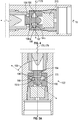
- FIG. 3A is an enlarged view of the pin assembly 160.
- the stopper 166 is configured to allow the firing pin 164 to have unimpeded axial motion to contact and detonate the initiator 210 ( Fig. 1 ) only after a longitudinal tool axis 178 of the pin assembly 160 has a predetermined angular deviation from a gravity vector, which defines a vertical direction. If the desired angular deviation is not present, then the stopper 166 stops the firing pin 164 from moving toward the initiator 210 ( Fig. 1 ). Thus, the firing head 100 is in the "safe" position / condition.
- the stopping action occurs through the physical interaction of a groove 190 formed on a shank 192 of the firing pin 164, the stopper 166, and the medial chamber 170.
- the groove 190 is partially defined by a ledge 198 that can be contacted by the stopper 166 under specific circumstances described below.
- the medial chamber 170 is defined by converging sloped surfaces 194a,b. Both surfaces 194a,b are non-orthogonal to the axis 178 and converge to one another in a radially outward direction. Both surfaces 194a,b have a slope sufficient to allow gravity to roll, slide, or pivot the stopper 166 into the groove 190 when the longitudinal axis 178 is parallel with gravity.
- the stopper 166 may be a freely moving body that can be moved ( e.g., slide, roll, rock, pivot, etc.) by gravity. By “freely moving” or “movable,” it is meant that the stopper 166 is not fixed, connected, or otherwise restricted from moving along a surface due to gravitational attraction.
- the stopper 166 may be formed as a sphere, a spheroid, ovoid, cylinder, etc.
- the stopper 166 is sized only to partially seat in the groove 190.
- the stopper 166 may be formed of a metal, ceramic, polymer, or any other material that will maintain structural integrity when compressed between the ledge 198 and the sloped surface 194a.
- the stopper 166 When part of the stopper 166 is in the groove 190 and the remainder of the stopper 166 is in the medial chamber 170, the stopper 166 prevents the firing pin 164 from moving a distance sufficient to strike and activate the initiator 210. Specifically, the stopper 166 acts as a physical barrier against which the ledge 198 strikes when then firing pin 164 slides toward the initiator 210. In the illustrated embodiment, the stopper 166 is shown radially offset from the longitudinal axis 178 and is smaller in size than the bore 168 of the housing 162. While one stopper 166 is shown, the stopper 166 may include two or more stopper elements.
- FIG. 3B is an enlarged view of another pin assembly 260 according to the present disclosure. Whereas the pin assembly 160 of Fig. 3A is shown in an "upright” position or orientation, the pin assembly 260 of Fig. 3B is shown in an "upside down” orientation. In the “upright” position, the pin 164 of Fig. 3A moves downward with gravity. In the “upright” position, the pin 164 of Fig. 3B moves upward against gravity.
- the pin assembly 260 is generally of the same configuration as the pin assembly 160 of Fig. 3A .
- the groove 290 formed on the shank 292 forms a recess that is radially wide enough to fit a majority of the stopper 166 or at least enough of the stopper 166 to have a center of gravity of the stopper 166 radially inward of an edge of a shoulder 298 on which the stopper 166 seats in the upside down orientation.
- the line 300 illustrates a line that intersects the center of gravity of the stopper 166.
- the shoulder 298 may have an undercut or sloped surface that is angled to have the stopper 166 move toward the shank 292.
- the stopper 166 In operation, if the pin assembly 260 is in an undesirable deviated orientation, then the stopper 166 is seated in the shoulder 298. If the pin 164 unintentionally moves, then the stopper 166 is lifted by the shoulder 298 until the stopper 166 contacts the surface 194b.
- the shoulder 298 may include a lip, projection, rim or other feature that presents a wall or other structure that retains the stopper 166 within the shoulder 298 during the lifting.
- the pin assembly 160 is shown in a horizontal orientation wherein the longitudinal axis 178 is roughly orthogonal to the gravity vector 179.
- the axial distances separating the surfaces 194a,b and the angle defined by the surfaces 194a,b form a recess 197.
- the recess 197 may be partial or complete annular space formed in the chamber 710.
- the recess 197 may be sized to seat the stopper 166 in the medial chamber 170 such that no portion of the stopper 166 protrudes into the groove 190 to a degree that interferes or blocks the sliding motion of the firing pin 164.
- the pin assembly 160 is shown in a vertical orientation relative to the gravity vector 179, which is co-linear with the longitudinal axis 178. This orientation may be indicative of a location in a wellbore where a detonation should not occur.
- the surface 194b has an angle 199 relative to the gravity vector 179 that enables gravity to keep the stopper 166 at least partially seated in the groove 190 in this vertical orientation.
- the stopper 166 has slid, rolled, or otherwise descended along the surface 194b to the "low point" in the chamber 170.
- the stopper 166 contacts and interferingly engages the firing pin 164 at the ledge 198 while being supported by surface 194b.
- the pin assembly 160 is shown in a deviated orientation relative to the gravity vector 179.
- This deviated orientation may be indicative of a location in a wellbore where a detonation also should not occur.
- the angle 200 relative to the longitudinal axis 178 continues to enable gravity to keep the stopper 166 at least partially seated in the groove 190 despite the deviated orientation.
- the stopper 166 contacts and interferingly engages the firing pin 164 at the ledge 198.
- the angular deviation from the gravity vector 179 after which the pin assembly 160 becomes fully functional can be readily adjusted by selecting an appropriate angle 200 for one or both of the surfaces 194a,b. That is, the more acute the angle, the greater the deviation required to have the stopper 166 completely out of the groove 190.
- firing head 100 One illustrative use of the firing head 100 will be discussed in connection with Figs. 1 - 7 . For clarity, the firing head 100 will be discussed with reference to perforating guns. It should be appreciated, however, that the firing head 100 is not limited to such use.
- the firing head 100 is incorporated into the tool 50.
- the downhole tool 50 may be conveyed along the vertical section 30 of the wellbore 14.
- the orientation of the firing head 100 may be less than the selected minimum value for a deviation. Therefore, if the firing pin 164 inadvertently slides toward the initiator 210 either due to being impacted by the contact member 144 or some other reason, the stopper 166 can obstruct movement of the firing pin 164 in the manner shown in Figs. 5A-B . Thus, no detonation or detonation train is created because the firing head 100 is in the "safe" position / condition.
- the orientation of the firing head 100 may be at or greater than the selected minimum angular value for a deviation.
- the selected value for the minimum angular deviation may be a 15 degree, 30 degree, 45 degree, 60 degree, 75 degree, a 90 degree, or another intervening value. Therefore, gravity allows the stopper 166 to move completely out of the groove 190. As shown in Fig. 6 , the stopper 166 is fully seated in the medial chamber 170. Therefore, upon contact by the contact pin 144, the firing pin 164 can travel axially unimpeded toward and strike the initiator 210.
- the firing head 100 may be considered to be in a "fire ready,” “ready” or “armed” position / condition.
- the percussion arrangement may include a booster charge 242 at a terminal end of a detonator cord 244.
- the booster charge 242 may include a quantity of energy material sufficient to generate a pressure wave with enough energy to break the frangible element 176 and propel the firing pin 164 into the initiator 210.
Landscapes
- Engineering & Computer Science (AREA)
- Geology (AREA)
- Life Sciences & Earth Sciences (AREA)
- Mining & Mineral Resources (AREA)
- Physics & Mathematics (AREA)
- Environmental & Geological Engineering (AREA)
- Fluid Mechanics (AREA)
- General Life Sciences & Earth Sciences (AREA)
- Geochemistry & Mineralogy (AREA)
- General Engineering & Computer Science (AREA)
- Portable Nailing Machines And Staplers (AREA)
- Processing Of Stones Or Stones Resemblance Materials (AREA)
- Automotive Seat Belt Assembly (AREA)
- Furnace Charging Or Discharging (AREA)
Claims (15)
- Zündkopf zum selektiven Aktivieren eines Zünders (210) von einem Untertagewerkzeug, gekennzeichnet durch:- ein Gehäuse (120) mit einer Bohrung (122) und einer radial vergrößerten Kammer (170), die entlang der Bohrung ausgebildet ist;- einen Zündstift (164), der in der Bohrung (122) angeordnet ist, wobei der Zündstift (164) einen Schaft (192) und eine Umfangsnut (190) aufweist, die auf einer Außenfläche des Schafts (192) ausgebildet ist; und- eine bewegliche Sperre (196), die in der radial vergrößerten Kammer (170) angeordnet ist, wobei die Sperre (196) nur teilweise in der Nut (190) angeordnet ist, wenn sich das Gehäuse (120) in einer senkrechten Lage befindet und sich die Sperre (196) aus der Nut (190) heraus bewegt, wenn das Gehäuse (120) eine vorgegebene Mindest-Winkelabweichung von der senkrechten Lage aufweist.
- Zündkopf nach Anspruch 1, außerdem dadurch gekennzeichnet, dass sich die Sperre (196) mindestens durch eines von Folgendem bewegt: (i) Rollen und (ii) Gleiten.
- Zündkopf nach einem der Ansprüche 1-2, außerdem dadurch gekennzeichnet, dass die Sperre (196) als eines von Folgendem ausgebildet ist: (i) eine Kugel, (ii) ein Sphäroid, (iii) ein Ovoid und (iv) ein Zylinder.
- Zündkopf nach einem der Ansprüche 1-3, außerdem dadurch gekennzeichnet, dass die Sperre (196) eine Vielzahl von Sperrenelemente umfasst.
- Zündkopf nach einem der Ansprüche 1-4, außerdem dadurch gekennzeichnet, dass die Sperre (196) einen Schwerpunkt aufweist, der von einer Kante eines Absatzes aus, in der die Sperre (196) sitzt, radial weiter innen liegt.
- Zündkopf nach einem der Ansprüche 1-5, außerdem dadurch gekennzeichnet, dass die Kammer (170) durch mindestens eine Fläche definiert ist, wobei die Fläche zu einer Längsachse des Gehäuses (120) geneigt ist, damit die Schwerkraft die Sperre (196) in der Nut (190) halten kann, wenn sich das Gehäuse (120) in der senkrechten Lage befindet.
- Zündkopf nach Anspruch 6, außerdem dadurch gekennzeichnet, dass die mindestens eine Fläche geneigt ist, damit die Schwerkraft die Sperre (196) in der Nut (190) halten kann, wenn das Gehäuse (120) um eine Winkelabweichung von nicht mehr als zehn Grad aus der senkrechten Lage gebracht wird.
- Zündkopf nach Anspruch 6, außerdem dadurch gekennzeichnet, dass die mindestens eine Fläche geneigt ist, damit die Schwerkraft die Sperre (196) in der Nut (190) halten kann, wenn das Gehäuse (120) um eine Winkelabweichung von nicht mehr als fünfundvierzig Grad aus der senkrechten Lage gebracht wird.
- Zündkopf nach einem der Ansprüche 1-8, außerdem dadurch gekennzeichnet, dass der Zündstift (164) ein erstes Ende aufweist, das dazu platziert ist, eine aufgebrachte Kraft aufzunehmen, sowie ein zweites Ende, das dazu konfiguriert ist, einen Zünder (210) zu berühren.
- Zündkopf nach einem der Ansprüche 1-9, außerdem dadurch gekennzeichnet, dass das Gehäuse (120) eine stehende Ausrichtung und eine auf den Kopf stehende Ausrichtung aufweist, wobei die Kammer durch eine erste Fläche und eine zweite Fläche definiert ist, wobei die erste Fläche zu einer Längsachse des Gehäuses (120) geneigt ist, damit die Schwerkraft die Sperre (196) in der Nut (190) halten kann, wenn sich das Gehäuse (120) in der stehenden Lage befindet, und wobei die zweite Fläche zu einer Längsachse des Gehäuses (120) geneigt ist, damit die Schwerkraft die Sperre (196) in der Nut (190) halten kann, wenn sich das Gehäuse (120) in der auf den Kopf stehenden Lage befindet.
- Verfahren zum selektiven Aktivieren eines Zünders (210) von einem Untertagewerkzeug, gekennzeichnet durch:Bilden eines Untertagewerkzeugs durch Platzieren eines Zündkopfs neben dem Zünder (210), wobei der Zündkopf gekennzeichnet ist durch:- ein Gehäuse (120) mit einer Bohrung (122) und einer radial vergrößerten Kammer (170), die entlang der Bohrung (122) ausgebildet ist;- einen Zündstift (164), der in der Bohrung (122) angeordnet ist, wobei der Zündstift (164) einen Schaft (192) und eine Umfangsnut (190) aufweist, die auf einer Außenfläche des Schafts (192) ausgebildet ist; und- eine Sperre (196), die in der radial vergrößerten Kammer (170) angeordnet ist, wobei die Sperre (196) nur teilweise in der Nut (190) angeordnet ist, wenn sich das Gehäuse (120) in einer senkrechten Lage befindet und sich die Sperre (196) aus der Nut (190) heraus bewegt, wenn das Gehäuse (120) eine vorgegebene Winkelabweichung von der senkrechten Lage aufweist;Leiten des Untertagewerkzeugs in ein Bohrloch, wobei die Sperre (196) verhindert, dass der Zündstift (164) den Zünder (210) berührt, sofern nicht die vorgegebene Winkelabweichung vorhanden ist.Platzieren des Untertagewerkzeugs an einem gewünschten Ort, wo die vorgegebene Winkelabweichung vorhanden ist; undAktivieren des Zünders (210) unter Verwendung des Zündkopfs.
- Verfahren nach Anspruch 11, außerdem dadurch gekennzeichnet, dass sich die Sperre (196) durch mindestens eines von Folgendem bewegt: (i) Rollen und (ii) Gleiten.
- Zündkopf nach einem der Ansprüche 11-12, außerdem dadurch gekennzeichnet, dass die Sperre (196) einen Schwerpunkt aufweist, der von einer Kante eines Absatzes aus, in der die Sperre (196) sitzt, radial weiter innen liegt.
- Zündkopf nach einem der Ansprüche 11-13, außerdem gekennzeichnet durch das Aufbringen einer Kraft auf das erste Ende des Zündstifts (164), wobei der Zündstift (164) sich als Reaktion auf die aufgebrachte Kraft bewegt und den Zünder (210) berührt.
- Zündkopf nach einem der Ansprüche 11-14, außerdem dadurch gekennzeichnet, dass das Gehäuse (120) eine stehende Ausrichtung und eine auf den Kopf stehende Ausrichtung aufweist, wobei die Kammer (170) durch eine erste Fläche und eine zweite Fläche definiert ist, wobei die erste Fläche zu einer Längsachse des Gehäuses (120) geneigt ist, damit die Schwerkraft die Sperre (196) in der Nut (190) halten kann, wenn sich das Gehäuse (120) in der stehenden Lage befindet, und wobei die zweite Fläche zu einer Längsachse des Gehäuses (120) geneigt ist, damit die Schwerkraft die Sperre (196) in der Nut (190) halten kann, wenn sich das Gehäuse (120) in der auf den Kopf stehenden Lage befindet.
Applications Claiming Priority (1)
| Application Number | Priority Date | Filing Date | Title |
|---|---|---|---|
| PCT/US2017/059350 WO2019089010A1 (en) | 2017-10-31 | 2017-10-31 | Safe firing head for deviated wellbores |
Publications (2)
| Publication Number | Publication Date |
|---|---|
| EP3704347A1 EP3704347A1 (de) | 2020-09-09 |
| EP3704347B1 true EP3704347B1 (de) | 2021-02-17 |
Family
ID=60570188
Family Applications (1)
| Application Number | Title | Priority Date | Filing Date |
|---|---|---|---|
| EP17808641.9A Not-in-force EP3704347B1 (de) | 2017-10-31 | 2017-10-31 | Sicherer zündkopf für abgewandte bohrlöcher |
Country Status (6)
| Country | Link |
|---|---|
| US (1) | US11162335B2 (de) |
| EP (1) | EP3704347B1 (de) |
| AU (1) | AU2017438059B2 (de) |
| CA (1) | CA3080886C (de) |
| MX (1) | MX2020004711A (de) |
| WO (1) | WO2019089010A1 (de) |
Family Cites Families (5)
| Publication number | Priority date | Publication date | Assignee | Title |
|---|---|---|---|---|
| US4862964A (en) * | 1987-04-20 | 1989-09-05 | Halliburton Company | Method and apparatus for perforating well bores using differential pressure |
| US5505261A (en) * | 1994-06-07 | 1996-04-09 | Schlumberger Technology Corporation | Firing head connected between a coiled tubing and a perforating gun adapted to move freely within a tubing string and actuated by fluid pressure in the coiled tubing |
| US5887654A (en) * | 1996-11-20 | 1999-03-30 | Schlumberger Technology Corporation | Method for performing downhole functions |
| US8596378B2 (en) * | 2010-12-01 | 2013-12-03 | Halliburton Energy Services, Inc. | Perforating safety system and assembly |
| US20150292850A1 (en) * | 2014-04-09 | 2015-10-15 | Owen Oil Tools Lp | Detonator output interrupter for downhole tools |
-
2017
- 2017-10-31 WO PCT/US2017/059350 patent/WO2019089010A1/en not_active Ceased
- 2017-10-31 CA CA3080886A patent/CA3080886C/en not_active Expired - Fee Related
- 2017-10-31 AU AU2017438059A patent/AU2017438059B2/en not_active Ceased
- 2017-10-31 MX MX2020004711A patent/MX2020004711A/es unknown
- 2017-10-31 US US16/760,337 patent/US11162335B2/en active Active
- 2017-10-31 EP EP17808641.9A patent/EP3704347B1/de not_active Not-in-force
Non-Patent Citations (1)
| Title |
|---|
| None * |
Also Published As
| Publication number | Publication date |
|---|---|
| AU2017438059A1 (en) | 2020-06-18 |
| EP3704347A1 (de) | 2020-09-09 |
| CA3080886A1 (en) | 2019-05-09 |
| MX2020004711A (es) | 2021-04-12 |
| US20210207460A1 (en) | 2021-07-08 |
| US11162335B2 (en) | 2021-11-02 |
| AU2017438059B2 (en) | 2020-08-20 |
| WO2019089010A1 (en) | 2019-05-09 |
| CA3080886C (en) | 2021-01-26 |
Similar Documents
| Publication | Publication Date | Title |
|---|---|---|
| CA3014081C (en) | Detonation transfer system | |
| EP3452684B1 (de) | Druckaktivierter selektiver perforierender schalterträger | |
| EP3452685B1 (de) | Direkt initiierte adressierbare stromladung | |
| US10174595B2 (en) | Perforating tool | |
| EP3663702B1 (de) | Auf eingangsöffnung abgestimmte geformte ladung | |
| US4830120A (en) | Methods and apparatus for perforating a deviated casing in a subterranean well | |
| US20190277103A1 (en) | Power cartridges for setting tools | |
| US20210108475A1 (en) | Impact Resistant Material in Setting Tool | |
| US11098563B1 (en) | Perforating gun connection system | |
| US20090050322A1 (en) | Wireless perforating gun initiation | |
| US10934794B2 (en) | Systems and methods for setting a downhole plug using a self damping setting tool | |
| US6684954B2 (en) | Bi-directional explosive transfer subassembly and method for use of same | |
| US10119349B2 (en) | Redundant drill string cutting system | |
| US10526876B2 (en) | Method and system for hydraulic communication with target well from relief well | |
| US11639637B2 (en) | System and method for centralizing a tool in a wellbore | |
| EP3105410B1 (de) | Zünderunterbrecher für bohrlochwerkzeuge | |
| US20210087897A1 (en) | Impact Resistant Material in Setting Tool | |
| US20150292850A1 (en) | Detonator output interrupter for downhole tools | |
| EP3704347B1 (de) | Sicherer zündkopf für abgewandte bohrlöcher | |
| WO2022271168A1 (en) | Pressure-actuated safety for well perforating | |
| US11566499B2 (en) | Pressure-actuated safety for well perforating |
Legal Events
| Date | Code | Title | Description |
|---|---|---|---|
| STAA | Information on the status of an ep patent application or granted ep patent |
Free format text: STATUS: UNKNOWN |
|
| STAA | Information on the status of an ep patent application or granted ep patent |
Free format text: STATUS: THE INTERNATIONAL PUBLICATION HAS BEEN MADE |
|
| PUAI | Public reference made under article 153(3) epc to a published international application that has entered the european phase |
Free format text: ORIGINAL CODE: 0009012 |
|
| STAA | Information on the status of an ep patent application or granted ep patent |
Free format text: STATUS: REQUEST FOR EXAMINATION WAS MADE |
|
| 17P | Request for examination filed |
Effective date: 20200526 |
|
| AK | Designated contracting states |
Kind code of ref document: A1 Designated state(s): AL AT BE BG CH CY CZ DE DK EE ES FI FR GB GR HR HU IE IS IT LI LT LU LV MC MK MT NL NO PL PT RO RS SE SI SK SM TR |
|
| AX | Request for extension of the european patent |
Extension state: BA ME |
|
| GRAP | Despatch of communication of intention to grant a patent |
Free format text: ORIGINAL CODE: EPIDOSNIGR1 |
|
| STAA | Information on the status of an ep patent application or granted ep patent |
Free format text: STATUS: GRANT OF PATENT IS INTENDED |
|
| DAV | Request for validation of the european patent (deleted) | ||
| DAX | Request for extension of the european patent (deleted) | ||
| INTG | Intention to grant announced |
Effective date: 20200915 |
|
| GRAJ | Information related to disapproval of communication of intention to grant by the applicant or resumption of examination proceedings by the epo deleted |
Free format text: ORIGINAL CODE: EPIDOSDIGR1 |
|
| STAA | Information on the status of an ep patent application or granted ep patent |
Free format text: STATUS: REQUEST FOR EXAMINATION WAS MADE |
|
| GRAP | Despatch of communication of intention to grant a patent |
Free format text: ORIGINAL CODE: EPIDOSNIGR1 |
|
| STAA | Information on the status of an ep patent application or granted ep patent |
Free format text: STATUS: GRANT OF PATENT IS INTENDED |
|
| INTC | Intention to grant announced (deleted) | ||
| GRAS | Grant fee paid |
Free format text: ORIGINAL CODE: EPIDOSNIGR3 |
|
| GRAA | (expected) grant |
Free format text: ORIGINAL CODE: 0009210 |
|
| STAA | Information on the status of an ep patent application or granted ep patent |
Free format text: STATUS: THE PATENT HAS BEEN GRANTED |
|
| INTG | Intention to grant announced |
Effective date: 20201221 |
|
| AK | Designated contracting states |
Kind code of ref document: B1 Designated state(s): AL AT BE BG CH CY CZ DE DK EE ES FI FR GB GR HR HU IE IS IT LI LT LU LV MC MK MT NL NO PL PT RO RS SE SI SK SM TR |
|
| REG | Reference to a national code |
Ref country code: GB Ref legal event code: FG4D |
|
| REG | Reference to a national code |
Ref country code: CH Ref legal event code: EP |
|
| REG | Reference to a national code |
Ref country code: DE Ref legal event code: R096 Ref document number: 602017032867 Country of ref document: DE |
|
| REG | Reference to a national code |
Ref country code: AT Ref legal event code: REF Ref document number: 1361707 Country of ref document: AT Kind code of ref document: T Effective date: 20210315 |
|
| REG | Reference to a national code |
Ref country code: IE Ref legal event code: FG4D |
|
| REG | Reference to a national code |
Ref country code: NO Ref legal event code: T2 Effective date: 20210217 |
|
| REG | Reference to a national code |
Ref country code: LT Ref legal event code: MG9D |
|
| REG | Reference to a national code |
Ref country code: NL Ref legal event code: MP Effective date: 20210217 |
|
| PG25 | Lapsed in a contracting state [announced via postgrant information from national office to epo] |
Ref country code: LT Free format text: LAPSE BECAUSE OF FAILURE TO SUBMIT A TRANSLATION OF THE DESCRIPTION OR TO PAY THE FEE WITHIN THE PRESCRIBED TIME-LIMIT Effective date: 20210217 Ref country code: BG Free format text: LAPSE BECAUSE OF FAILURE TO SUBMIT A TRANSLATION OF THE DESCRIPTION OR TO PAY THE FEE WITHIN THE PRESCRIBED TIME-LIMIT Effective date: 20210517 Ref country code: GR Free format text: LAPSE BECAUSE OF FAILURE TO SUBMIT A TRANSLATION OF THE DESCRIPTION OR TO PAY THE FEE WITHIN THE PRESCRIBED TIME-LIMIT Effective date: 20210518 Ref country code: FI Free format text: LAPSE BECAUSE OF FAILURE TO SUBMIT A TRANSLATION OF THE DESCRIPTION OR TO PAY THE FEE WITHIN THE PRESCRIBED TIME-LIMIT Effective date: 20210217 Ref country code: HR Free format text: LAPSE BECAUSE OF FAILURE TO SUBMIT A TRANSLATION OF THE DESCRIPTION OR TO PAY THE FEE WITHIN THE PRESCRIBED TIME-LIMIT Effective date: 20210217 Ref country code: PT Free format text: LAPSE BECAUSE OF FAILURE TO SUBMIT A TRANSLATION OF THE DESCRIPTION OR TO PAY THE FEE WITHIN THE PRESCRIBED TIME-LIMIT Effective date: 20210617 |
|
| REG | Reference to a national code |
Ref country code: AT Ref legal event code: MK05 Ref document number: 1361707 Country of ref document: AT Kind code of ref document: T Effective date: 20210217 |
|
| PG25 | Lapsed in a contracting state [announced via postgrant information from national office to epo] |
Ref country code: SE Free format text: LAPSE BECAUSE OF FAILURE TO SUBMIT A TRANSLATION OF THE DESCRIPTION OR TO PAY THE FEE WITHIN THE PRESCRIBED TIME-LIMIT Effective date: 20210217 Ref country code: LV Free format text: LAPSE BECAUSE OF FAILURE TO SUBMIT A TRANSLATION OF THE DESCRIPTION OR TO PAY THE FEE WITHIN THE PRESCRIBED TIME-LIMIT Effective date: 20210217 Ref country code: PL Free format text: LAPSE BECAUSE OF FAILURE TO SUBMIT A TRANSLATION OF THE DESCRIPTION OR TO PAY THE FEE WITHIN THE PRESCRIBED TIME-LIMIT Effective date: 20210217 Ref country code: NL Free format text: LAPSE BECAUSE OF FAILURE TO SUBMIT A TRANSLATION OF THE DESCRIPTION OR TO PAY THE FEE WITHIN THE PRESCRIBED TIME-LIMIT Effective date: 20210217 Ref country code: RS Free format text: LAPSE BECAUSE OF FAILURE TO SUBMIT A TRANSLATION OF THE DESCRIPTION OR TO PAY THE FEE WITHIN THE PRESCRIBED TIME-LIMIT Effective date: 20210217 |
|
| PG25 | Lapsed in a contracting state [announced via postgrant information from national office to epo] |
Ref country code: IS Free format text: LAPSE BECAUSE OF FAILURE TO SUBMIT A TRANSLATION OF THE DESCRIPTION OR TO PAY THE FEE WITHIN THE PRESCRIBED TIME-LIMIT Effective date: 20210617 |
|
| PG25 | Lapsed in a contracting state [announced via postgrant information from national office to epo] |
Ref country code: SM Free format text: LAPSE BECAUSE OF FAILURE TO SUBMIT A TRANSLATION OF THE DESCRIPTION OR TO PAY THE FEE WITHIN THE PRESCRIBED TIME-LIMIT Effective date: 20210217 Ref country code: AT Free format text: LAPSE BECAUSE OF FAILURE TO SUBMIT A TRANSLATION OF THE DESCRIPTION OR TO PAY THE FEE WITHIN THE PRESCRIBED TIME-LIMIT Effective date: 20210217 Ref country code: EE Free format text: LAPSE BECAUSE OF FAILURE TO SUBMIT A TRANSLATION OF THE DESCRIPTION OR TO PAY THE FEE WITHIN THE PRESCRIBED TIME-LIMIT Effective date: 20210217 Ref country code: CZ Free format text: LAPSE BECAUSE OF FAILURE TO SUBMIT A TRANSLATION OF THE DESCRIPTION OR TO PAY THE FEE WITHIN THE PRESCRIBED TIME-LIMIT Effective date: 20210217 |
|
| REG | Reference to a national code |
Ref country code: DE Ref legal event code: R097 Ref document number: 602017032867 Country of ref document: DE |
|
| PG25 | Lapsed in a contracting state [announced via postgrant information from national office to epo] |
Ref country code: RO Free format text: LAPSE BECAUSE OF FAILURE TO SUBMIT A TRANSLATION OF THE DESCRIPTION OR TO PAY THE FEE WITHIN THE PRESCRIBED TIME-LIMIT Effective date: 20210217 Ref country code: SK Free format text: LAPSE BECAUSE OF FAILURE TO SUBMIT A TRANSLATION OF THE DESCRIPTION OR TO PAY THE FEE WITHIN THE PRESCRIBED TIME-LIMIT Effective date: 20210217 Ref country code: DK Free format text: LAPSE BECAUSE OF FAILURE TO SUBMIT A TRANSLATION OF THE DESCRIPTION OR TO PAY THE FEE WITHIN THE PRESCRIBED TIME-LIMIT Effective date: 20210217 |
|
| PLBE | No opposition filed within time limit |
Free format text: ORIGINAL CODE: 0009261 |
|
| STAA | Information on the status of an ep patent application or granted ep patent |
Free format text: STATUS: NO OPPOSITION FILED WITHIN TIME LIMIT |
|
| 26N | No opposition filed |
Effective date: 20211118 |
|
| PG25 | Lapsed in a contracting state [announced via postgrant information from national office to epo] |
Ref country code: ES Free format text: LAPSE BECAUSE OF FAILURE TO SUBMIT A TRANSLATION OF THE DESCRIPTION OR TO PAY THE FEE WITHIN THE PRESCRIBED TIME-LIMIT Effective date: 20210217 Ref country code: AL Free format text: LAPSE BECAUSE OF FAILURE TO SUBMIT A TRANSLATION OF THE DESCRIPTION OR TO PAY THE FEE WITHIN THE PRESCRIBED TIME-LIMIT Effective date: 20210217 |
|
| PGFP | Annual fee paid to national office [announced via postgrant information from national office to epo] |
Ref country code: NO Payment date: 20211026 Year of fee payment: 5 Ref country code: DE Payment date: 20211027 Year of fee payment: 5 Ref country code: GB Payment date: 20211021 Year of fee payment: 5 |
|
| PGFP | Annual fee paid to national office [announced via postgrant information from national office to epo] |
Ref country code: IT Payment date: 20211027 Year of fee payment: 5 Ref country code: FR Payment date: 20211029 Year of fee payment: 5 |
|
| REG | Reference to a national code |
Ref country code: CH Ref legal event code: PL |
|
| PG25 | Lapsed in a contracting state [announced via postgrant information from national office to epo] |
Ref country code: IS Free format text: LAPSE BECAUSE OF FAILURE TO SUBMIT A TRANSLATION OF THE DESCRIPTION OR TO PAY THE FEE WITHIN THE PRESCRIBED TIME-LIMIT Effective date: 20210617 |
|
| REG | Reference to a national code |
Ref country code: BE Ref legal event code: MM Effective date: 20211031 |
|
| PG25 | Lapsed in a contracting state [announced via postgrant information from national office to epo] |
Ref country code: MC Free format text: LAPSE BECAUSE OF FAILURE TO SUBMIT A TRANSLATION OF THE DESCRIPTION OR TO PAY THE FEE WITHIN THE PRESCRIBED TIME-LIMIT Effective date: 20210217 |
|
| PG25 | Lapsed in a contracting state [announced via postgrant information from national office to epo] |
Ref country code: LU Free format text: LAPSE BECAUSE OF NON-PAYMENT OF DUE FEES Effective date: 20211031 Ref country code: BE Free format text: LAPSE BECAUSE OF NON-PAYMENT OF DUE FEES Effective date: 20211031 |
|
| PG25 | Lapsed in a contracting state [announced via postgrant information from national office to epo] |
Ref country code: LI Free format text: LAPSE BECAUSE OF NON-PAYMENT OF DUE FEES Effective date: 20211031 Ref country code: CH Free format text: LAPSE BECAUSE OF NON-PAYMENT OF DUE FEES Effective date: 20211031 |
|
| PG25 | Lapsed in a contracting state [announced via postgrant information from national office to epo] |
Ref country code: IE Free format text: LAPSE BECAUSE OF NON-PAYMENT OF DUE FEES Effective date: 20211031 |
|
| REG | Reference to a national code |
Ref country code: DE Ref legal event code: R119 Ref document number: 602017032867 Country of ref document: DE |
|
| REG | Reference to a national code |
Ref country code: NO Ref legal event code: MMEP |
|
| GBPC | Gb: european patent ceased through non-payment of renewal fee |
Effective date: 20221031 |
|
| PG25 | Lapsed in a contracting state [announced via postgrant information from national office to epo] |
Ref country code: CY Free format text: LAPSE BECAUSE OF FAILURE TO SUBMIT A TRANSLATION OF THE DESCRIPTION OR TO PAY THE FEE WITHIN THE PRESCRIBED TIME-LIMIT Effective date: 20210217 |
|
| PG25 | Lapsed in a contracting state [announced via postgrant information from national office to epo] |
Ref country code: NO Free format text: LAPSE BECAUSE OF NON-PAYMENT OF DUE FEES Effective date: 20221031 Ref country code: HU Free format text: LAPSE BECAUSE OF FAILURE TO SUBMIT A TRANSLATION OF THE DESCRIPTION OR TO PAY THE FEE WITHIN THE PRESCRIBED TIME-LIMIT; INVALID AB INITIO Effective date: 20171031 Ref country code: FR Free format text: LAPSE BECAUSE OF NON-PAYMENT OF DUE FEES Effective date: 20221031 Ref country code: DE Free format text: LAPSE BECAUSE OF NON-PAYMENT OF DUE FEES Effective date: 20230503 |
|
| PG25 | Lapsed in a contracting state [announced via postgrant information from national office to epo] |
Ref country code: SI Free format text: LAPSE BECAUSE OF FAILURE TO SUBMIT A TRANSLATION OF THE DESCRIPTION OR TO PAY THE FEE WITHIN THE PRESCRIBED TIME-LIMIT Effective date: 20210217 |
|
| PG25 | Lapsed in a contracting state [announced via postgrant information from national office to epo] |
Ref country code: IT Free format text: LAPSE BECAUSE OF NON-PAYMENT OF DUE FEES Effective date: 20221031 Ref country code: GB Free format text: LAPSE BECAUSE OF NON-PAYMENT OF DUE FEES Effective date: 20221031 |
|
| PG25 | Lapsed in a contracting state [announced via postgrant information from national office to epo] |
Ref country code: MK Free format text: LAPSE BECAUSE OF FAILURE TO SUBMIT A TRANSLATION OF THE DESCRIPTION OR TO PAY THE FEE WITHIN THE PRESCRIBED TIME-LIMIT Effective date: 20210217 |
|
| PG25 | Lapsed in a contracting state [announced via postgrant information from national office to epo] |
Ref country code: TR Free format text: LAPSE BECAUSE OF FAILURE TO SUBMIT A TRANSLATION OF THE DESCRIPTION OR TO PAY THE FEE WITHIN THE PRESCRIBED TIME-LIMIT Effective date: 20210217 |
|
| PG25 | Lapsed in a contracting state [announced via postgrant information from national office to epo] |
Ref country code: MT Free format text: LAPSE BECAUSE OF FAILURE TO SUBMIT A TRANSLATION OF THE DESCRIPTION OR TO PAY THE FEE WITHIN THE PRESCRIBED TIME-LIMIT Effective date: 20210217 |