EP3704922A1 - Agencement des socs et machine de distribution dotée d'un agencement des socs - Google Patents
Agencement des socs et machine de distribution dotée d'un agencement des socs Download PDFInfo
- Publication number
- EP3704922A1 EP3704922A1 EP20401005.2A EP20401005A EP3704922A1 EP 3704922 A1 EP3704922 A1 EP 3704922A1 EP 20401005 A EP20401005 A EP 20401005A EP 3704922 A1 EP3704922 A1 EP 3704922A1
- Authority
- EP
- European Patent Office
- Prior art keywords
- coulter
- support arm
- disc
- arrangement
- furrow former
- Prior art date
- Legal status (The legal status is an assumption and is not a legal conclusion. Google has not performed a legal analysis and makes no representation as to the accuracy of the status listed.)
- Granted
Links
Images


Classifications
-
- A—HUMAN NECESSITIES
- A01—AGRICULTURE; FORESTRY; ANIMAL HUSBANDRY; HUNTING; TRAPPING; FISHING
- A01C—PLANTING; SOWING; FERTILISING
- A01C5/00—Making or covering furrows or holes for sowing, planting or manuring
- A01C5/06—Machines for making or covering drills or furrows for sowing or planting
- A01C5/062—Devices for making drills or furrows
- A01C5/064—Devices for making drills or furrows with rotating tools
Definitions
- the invention relates to a coulter arrangement according to the preamble of patent claim 1 and a distributing machine with a coulter arrangement according to the preamble of claim 10.
- This coulter arrangement for a disc coulter designed as a fertilizer coulter comprises a support arm for fastening the coulter arrangement to a frame of the distributing machine. Furthermore, the coulter arrangement comprises a coulter disc rotatably mounted on the lower end of the support arm facing away from the attachment to the frame, and a furrow former. During operation, the coulter disc is guided through the ground at the desired working depth on the support arm, the furrow former being able to be arranged relative to the coulter disc at the lower end of the support arm by means of a holding device.
- the distribution machine further comprises a storage container for seed and / or fertilizer, which is connected via at least one application device by means of application lines to a plurality of disc coulters, in particular the furrow formers, arranged side by side transversely to the direction of travel.
- the distributor is thus set up to distribute seeds and / or fertilizer over the disc coulters.
- the holding device has a plate-like coulter carrier which is attached to the furrow former and thus supports it.
- the furrow former is releasably fastened to the support arm via the coulter carrier by means of two fastening bolts arranged at a distance from one another.
- the fastening bolts are designed as screw bolts and penetrate the support arm and the coulter carrier at the holes provided for this purpose.
- the coulter carrier is releasably secured to the support arm with the aid of two securing elements, which can be screwed onto the screw bolts and are designed as securing nuts, with associated washers to prevent the securing elements from being accidentally released.
- the disadvantage of this coulter arrangement is that the two fastening bolts form an axis about which the furrow former can pivot with respect to the support arm and in particular the coulter disc.
- the storage of the furrow former is thus under-determined in the axial direction, so that a secure arrangement of the furrow former relative to the coulter disc is not possible.
- This is particularly disadvantageous since the aim is to keep the furrow former at least approximately in contact with the coulter disc in order to create defined storage conditions for seeds and / or fertilizer for the distributor by means of the coulter arrangement.
- the object on which the invention is based is thus to create a simple and secure attachment for a defined assignment of the furrow former to the coulter disc.
- This object is achieved according to the invention in that at least three fastening bolts are provided, the at least three fastening bolts being arranged so as to form the corner points of a triangle.
- a tilt-proof fastening of the furrow former on the support arm is created.
- the three fastening bolts arranged in a triangle with respect to one another achieve a specific mounting of the furrow former on the support arm, so that a defined arrangement of the furrow former relative to the coulter disc is made possible.
- the invention makes use of the knowledge that the arrangement of at least one third fastening bolt, which is not on the axis between the other two fastening bolts, creates a secure fastening for the defined assignment of the furrow former to the coulter disc in a particularly simple and expedient manner.
- At least one elastic spring element is assigned to the at least three fastening bolts on the side of the coulter carrier facing away from the support arm and between the coulter carrier and the carrier arm, preferably in each case and / or on each side of the coulter carrier.
- the use of elastic spring elements allows the furrow former to move over the coulter carrier by means of the spring elements Can adapt the contour of the coulter disc. The assignment of the furrow former to the coulter disc is thus further improved in an advantageous manner.
- the spring elements can be designed as elastic, at least approximately ring-shaped rubber disks which have a recess for threading the spring element onto a fastening bolt.
- the spring elements can be designed as a mat-like disc element which has at least three recesses for threading onto the at least three fastening bolts.
- the coulter disc is rotatably mounted on the support arm at least approximately within the triangle spanned by the fastening bolts.
- the at least three fastening bolts which form the corner points of a triangle, penetrate the support arm and thus span a triangle on the support arm between them. Because the coulter disc is mounted at least approximately within this triangle, the axis of rotation of the coulter disc also lies within this triangle. Investigations have shown that an arrangement of this type is particularly robust against shocks and vibrations, so that the arrangement of the furrow former relative to the coulter disc is improved, especially in operation that engages the ground. This development is consequently characterized by a particularly secure and robust mounting of the coulter disc.
- the coulter carrier has at least two spaced apart recess images with at least three recesses penetrable by the fastening bolts, that the furrow former by means of the at least two recess images via the at least three fastening bolts in at least two different positions to the coulter disc is attachable.
- the recess images are preferably arranged at different distances from the center point of the coulter disc, so that the furrow former can be fastened to the support arm in different positions relative to the coulter disc.
- the coulter arrangement is also advantageously further developed in that the support arm has at least two spaced apart drilling patterns, each with at least three bores penetrable by the fastening bolts, the furrow former being attachable to the support arm in at least two different positions by means of the at least two drilling patterns via the at least three fastening bolts .
- the drilling patterns are preferably arranged in a circle around the center of the coulter disc, so that the furrow former is rotated in the different positions to the support arm relative to the axis of rotation of the coulter disc, so that the arrangement of the furrow former relative to the coulter disc hardly changes.
- the working depth of the coulter disc can be changed by pivoting the support arm.
- the frame is at least partially rotatable, so that the support arm can be pivoted by rotating the frame part to which it is attached.
- the furrow former can be fastened in an adapted position to the support arm by means of the at least two drilling patterns, the assignment to the coulter disc not changing at least approximately.
- the angle of the furrow former to the ground surface can be adjusted in that the furrow former is fastened in a different position to the support arm, the support arm not being pivoted.
- the support arm can have more than two drilling patterns arranged at a distance from one another.
- the spring elements can be pretensioned to act in the direction of the coulter disc, with at least one fastening bolt means which are set up to adjustably bias the spring elements assigned to the fastening bolt assigned.
- the force with which the furrow former is held to the coulter disc on the support arm can be adjusted by the bias of the spring elements. If a high bias of the spring elements is set by actuating the means, the fastening of the furrow former is particularly rigid. If the preload is low, the arrangement of the furrow former on the support arm is at least partially elastic.
- the means comprise at least one pressure disc and at least one clamping body, so that the pressure disc can be pressed against the coulter carrier and / or the support arm by means of the clamping body.
- the clamping body is preferably designed as a clamping nut that can be screwed onto a fastening bolt designed as a screw bolt.
- the pressure disk is preferably designed as a washer which can be pushed onto a fastening bolt.
- the thrust washer and the clamping body can be designed in one piece, that is, not detachably connected.
- the tensioning body can preferably be releasably fixed to a fastening bolt, so that the pretensioning of a spring element can be adjusted by fixing the tensioning body in a certain position, which causes a corresponding, preferably elastic, deformation of the spring element.
- the preload of the spring elements can be adjusted to the extent with which the pressure disk is pressed by means of the clamping body.
- the furrow former is at least approximately automatically held in contact with the coulter disc by means of the spring elements.
- the furrow former is attached to the support arm and guided through the ground and thus experiences abrasive wear.
- the advantage here is that, as a result of this measure, the attachment is further developed so that it automatically readjusts itself as the furrow former becomes worn, i.e. keeps the furrow former at least approximately in contact with the coulter disc as the material thickness decreases. This is particularly useful as it reduces the risk of blockages between the furrow former and the coulter disc due to plant residues.
- the coulter arrangement is also advantageously further developed in that the furrow former is at least partially resiliently attached to the support arm by means of the spring elements associated with the at least three fastening bolts, in particular in relation to the coulter disc.
- the furrow former of which is designed to perform evasive movements, in particular transverse to the direction of travel, so that damage is at least partially avoided when hitting obstacles in the ground.
- the holding device is designed in one piece with the furrow former, the holding device being at least partially designed as a distribution line.
- the holding device In order to deliver seeds and / or fertilizer directly into the intended furrow created by the furrow former, it is expedient for the holding device to be at least partially usable as a distribution line.
- the lower end of the holding device is preferably designed as a distribution line. The material can thus be delivered particularly close to the desired point and an additional distribution line can at least partially be omitted.
- the holding device can be used twice. It is further advantageous that by designing the holding device with the furrow former as one part, the furrow former is secured to the support arm so that it cannot be lost.
- the object on which the invention is based is also achieved by a distributing machine of the type mentioned at the outset, the distributing machine comprising at least one disc coulter arranged on a frame of the distributing machine via a coulter arrangement and the coulter arrangement being designed according to at least one of the embodiments described above.
- the distributing machine comprising at least one disc coulter arranged on a frame of the distributing machine via a coulter arrangement and the coulter arrangement being designed according to at least one of the embodiments described above.
- the working depth of the disc coulter can be adjusted by rotating the frame, the furrow former being able to be attached to the support arm via the at least two drilling patterns of the support arm, adapted to the working depth of the coulter disc.
- the furrow former can be attached to the support arm via the at least two drilling patterns in a position rotated around the center of the disk.
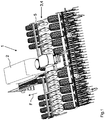
- a distribution machine 1 for spreading seeds and / or fertilizer on an agricultural area is shown in Fig.1 shown.
- the distribution machine 1 comprises a storage container 2, elongated in the direction of travel F, for the material to be dispensed.
- a concealed discharge device is arranged, which feeds material from the storage container 2 into a plurality of discharge lines, not shown.
- the distributing machine 2 further comprises a plurality of disc coulters 3.
- the disc coulters 3 are transverse to the direction of travel F arranged next to one another via a coulter arrangement 4 on a frame 5 of the distribution machine 1 and are thus moved through the soil of the agricultural area when the distribution machine 1 is in operation.
- the disc coulters 3 are each connected to the application device via one of the application lines (not shown).
- the frame 5 can be rotated so that the disc coulters 3 are carried at a different height in relation to the chassis of the distributing machine 1.
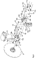
- FIG Fig. 2 One of the coulter arrangements 4 in the detached state from the distributor 1 is shown in FIG Fig. 2 shown.
- the coulter arrangement 4 for the disc coulter 3 designed as a fertilizer coulter is arranged via a bearing 6 on the frame 5 of the distributing machine 1 designed as a square tube and comprises, in addition to the coulter disk 3, a wedge-like furrow former 7.
- the bearing 6 has an upper bearing shell 6a and a lower bearing shell 6b , which are set up together to encompass the frame 5 so that the coulter arrangement 4 is carried on the frame 5.
- the upper and lower bearing shells 6a, b are releasably fastened to one another by means of fastening means designed as screw-nut connections and include elastic bearing elements 6c, which are designed as elongated round rubbers, for damping purposes.
- the lower bearing shell 6b is non-detachably connected to a support arm 8, at the lower end of which the coulter disk 3 is rotatably mounted about an axis of rotation R.
- the wedge-like furrow former 7 widens towards the rear in the direction of travel F, so that a furrow remains when moving through the ground, and is likewise fastened to the lower end of the support arm 8 by means of a holding device 9.
- the holding device 9 comprises a flange-like coulter carrier 10 which is not detachably connected to the furrow former 7.
- the furrow former 7 is fastened to the support arm 8 via the coulter carrier 10 by means of a total of three fastening bolts designed as screw bolts 11.
- the screw bolts 11 penetrate the support arm 8 at bores 8a and the coulter support 10 at recesses 10a brought into congruence with the bores 8a and are secured at their free end facing away from the coulter disk 3 with a nut 11a against unintentional shaking.
- the bolts 11 form in side view, transverse to Seen in the direction of travel, the corner points A, B, C of a triangle ABC.
- the attachment of the furrow former 7 to the support arm 8 is thus designed to be particularly tilt-proof and simple.
- the three screw bolts 11 arranged in the triangle ABC hold the furrow former 7 particularly reliably in contact with the coulter disc 3, so that the coulter arrangement 4 is characterized by a particularly reliable and constant quality of work.
- the coulter disc 3 is rotatably mounted on the support arm 8 within the triangle ABC, that is, the axis of rotation R lies within the triangle ABC and is at least approximately perpendicular to it.
- the furrow former 7 can be connected to the application lines (not shown) via the holding device 9, which is at least partially designed as a distribution line 12.
- the material discharged by the discharge device is then discharged at least partially via the pipe-like distribution line 12 to the furrow former 7, which is moved through the ground together with the coulter disc 3, and is thus worked into the ground via the furrow created.
- the holding device 9 is expediently made in one piece, that is to say not detachably connected, with the furrow former 7.
- the frame 5 of the distributing machine 1 can be rotated, as mentioned above. Due to the link-like connection of the coulter disc 3 and the furrow former 7 via the support arm 8 on the frame 5, these pivot upwards or downwards when the frame 5 is rotated, depending on the direction of rotation.
- the coulter disc 3 and the furrow former 7 are then carried at a different height in relation to the frame 5 or the chassis of the distributor 1, so that they have a different working depth. Since the furrow former 7 is rotated about the bearing 6 via the support arm 8 acting as a lever arm, the furrow former 7 is at a different angle to the ground.
- each of the drilling patterns 13a, 13b consists of three corresponding bores 8a, the bores 8a of the drilling pattern 13b running ahead of the drilling pattern 13a about the axis of rotation R clockwise in FIG Fig. 3 .
- the furrow former 7 can consequently be fastened to the support arm 8 in two different positions by means of the two drilling patterns 13a, 13b via the three screw bolts 11 by inserting the screw bolts 11 either through the bores 8a of one or the other drilling pattern 13a or 13b. In this way, an angle adjustment of the furrow former 7 to the support arm 8 or to the surface of the soil to be worked is realized.
- the furrow former 7 can consequently be attached to the support arm 8 via the drilling patterns 13a, 13b, adapted to the working depth of the coulter disc 3. With a given working depth of the coulter disc 3, the angle at which the support arm 8 stands to the ground via the bearing 6 on the frame 5 is known, so that the furrow former 7 can be aligned accordingly. In this way, the delivery angle of the seed and / or fertilizer supplied from the furrow former 7 via the tubular distribution line 12 can be adjusted, as can the shape of the furrow produced by the furrow former 7.
- the furrow former 7 can be fastened in a rotated position relative to the support arm 8 by means of the drilling patterns 13a, 13b.
- the arrangement of the drilling patterns 13a, 13b at a distance rotated about the axis of rotation R offers the advantage that the association between the furrow former 7 and the coulter disc 3 is hardly changed as a result.
- the support arm 8 has further drilling patterns 13a, 13b spaced apart in the vertical and / or horizontal direction.
- the coulter carrier 10 has three recess patterns 14a, 14b, 14c arranged at a distance from one another, such as Fig. 3 shows.
- Each of the recess images 14a, 14b, 14c is composed of three corresponding recesses 10a in the coulter carrier 10, the recesses 10a of the recess pattern 14a each being arranged in at least an approximately vertical direction above those of the recess patterns 14b, 14c, so that the furrow former 7 is carried on the coulter disc 3, offset radially outwards, when the Screw bolts 11 are guided through the recesses 10a of the recess pattern 14a.
- the recesses 10a of the recess pattern 14c are arranged corresponding to the opposite end position of the furrow former 7, near the axis of rotation R of the coulter disc 3, at the bottom of the coulter carrier 10, so that the furrow former 7 is offset radially inward on the coulter disc 3 from the support arm 8 or the screw bolts 11 is worn.
- the middle position of the furrow former 7 on the coulter disc 3 via the coulter carrier 10 attached to the support arm 8 is shown in FIG Fig. 4 shown in detail view.
- the screw bolts 11 reach through the support arm 8 in the drilling pattern 13b, which is brought into congruence with the recess pattern 14b in the coulter carrier 10, so that the furrow former 7 is supported on the coulter disc 3 at a medium distance from the axis of rotation R.
- the furrow former 7 can consequently be attached to the coulter disc in three different positions by means of the three recess patterns 14a-c via the screw bolts 11.
- the three positions of the furrow former 7 differ with regard to the distance at which it is carried to the axis of rotation R of the coulter disc 3 or the working depth at which the furrow former 7 operates relative to the coulter disc 3.
- the screw bolts 11 on both sides of the coulter support 10, that is, on the side of the coulter support 10 facing away from the support arm 8 and between the coulter support 10 and support arm 8, are each assigned an elastic spring element designed as a spring ring 15.
- the spring washers 15 are preferably made of an elastic plastic and are threaded onto the screw bolts 11 in the previously described arrangement in front of the nuts 11a so that the furrow former 7 is resiliently attached to the coulter disc 3 on the support arm 8.
- the spring washers 15 can be pre-tensioned in the direction of the coulter disk 3 by means of the nuts 11a, in that the nuts 11a are tightened onto the screw bolts 11 with a defined torque.
- the nuts 11a are integral with a Washer 11b executed.
- the washer 11b is pressed in the direction of the coulter support 10 or the support arm 8 by screwing on the nut 11a, since the screw bolts 11 are fixed on the opposite side of the support arm 8.
- the nut 11a acts as a tensioning body for the washer 11b, which serves as a pressure disk, in order to tension the spring washers 15.
- the spring washers 15 can consequently be impressed with a deformation defined via the tightening torque by the nuts 11a.
- the deformation is in turn a measure of the pretensioning force of the spring washers 15 in the direction of the coulter disc 3, so that the force with which the furrow former 7 is automatically held in contact with the coulter disc 3 via the spring washers 15 interacting with the screw bolts 11 can be set.
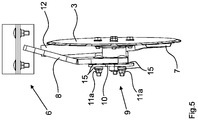
- Fig. 5 the coulter arrangement 4 can be seen in a front view against the direction of travel F.
- the furrow former 7 is held in contact with the coulter disc 3 via the holding device 9.
- the coulter disc 3 and the furrow former 7 are attached to the frame 5 of the distributing machine 1 via the bearing 6 and are moved together through the soil of the field to be worked.
- seed and / or fertilizer is discharged via the distribution line 12 into the furrow prepared by the furrow former 7 and thus worked into the soil.
- the arrangement of the furrow former 7 in relation to the support arm 8 can be adjusted by means of the drilling patterns 13a, 13b, so that the furrow former 7 can be carried at different angles to the ground.
- the distance between the furrow former 7 and the circumference of the coulter disc 3 by guiding the screw bolts 11 through one of the recess formers 14a-c.
- the working depth of the furrow former 7 is thus adjustable relative to the working depth of the coulter disc 3.
- the spring washers 15 By means of the spring washers 15, the furrow former 7 is automatically held in contact with the coulter disc 3 even with increasing wear.
- the furrow former 7 is set up by means of the spring rings 15 to give way in a springy manner when it hits obstacles in the ground, such as stones.
Landscapes
- Life Sciences & Earth Sciences (AREA)
- Soil Sciences (AREA)
- Environmental Sciences (AREA)
- Sowing (AREA)
Applications Claiming Priority (1)
| Application Number | Priority Date | Filing Date | Title |
|---|---|---|---|
| DE102019105624.1A DE102019105624A1 (de) | 2019-03-06 | 2019-03-06 | Scharanordnung und Verteilmaschine mit einer Scharanordnung |
Publications (3)
| Publication Number | Publication Date |
|---|---|
| EP3704922A1 true EP3704922A1 (fr) | 2020-09-09 |
| EP3704922C0 EP3704922C0 (fr) | 2024-08-14 |
| EP3704922B1 EP3704922B1 (fr) | 2024-08-14 |
Family
ID=69528742
Family Applications (1)
| Application Number | Title | Priority Date | Filing Date |
|---|---|---|---|
| EP20401005.2A Active EP3704922B1 (fr) | 2019-03-06 | 2020-01-22 | Agencement des socs et machine de distribution dotée d'un agencement des socs |
Country Status (2)
| Country | Link |
|---|---|
| EP (1) | EP3704922B1 (fr) |
| DE (1) | DE102019105624A1 (fr) |
Citations (4)
| Publication number | Priority date | Publication date | Assignee | Title |
|---|---|---|---|---|
| WO1988005997A1 (fr) * | 1987-02-19 | 1988-08-25 | Kurt Hansson | Distributeur combine pour l'agriculture |
| DE102006007624A1 (de) * | 2006-02-18 | 2007-08-23 | Rauch Landmaschinenfabrik Gmbh | Sämaschine zum reihenweisen Einbringen von Saatgut in den Boden |
| WO2010138068A1 (fr) * | 2009-05-29 | 2010-12-02 | Väderstad-Verken Aktiebolag | Disque pour un accessoire agricole |
| WO2014105560A2 (fr) * | 2012-12-27 | 2014-07-03 | Agco-Amity Jv, Llc | Montage de sabot de semence |
Family Cites Families (1)
| Publication number | Priority date | Publication date | Assignee | Title |
|---|---|---|---|---|
| US7357193B2 (en) * | 2005-09-19 | 2008-04-15 | Air Design, Inc. | Air seeder disc scraper |
-
2019
- 2019-03-06 DE DE102019105624.1A patent/DE102019105624A1/de active Pending
-
2020
- 2020-01-22 EP EP20401005.2A patent/EP3704922B1/fr active Active
Patent Citations (5)
| Publication number | Priority date | Publication date | Assignee | Title |
|---|---|---|---|---|
| WO1988005997A1 (fr) * | 1987-02-19 | 1988-08-25 | Kurt Hansson | Distributeur combine pour l'agriculture |
| DE102006007624A1 (de) * | 2006-02-18 | 2007-08-23 | Rauch Landmaschinenfabrik Gmbh | Sämaschine zum reihenweisen Einbringen von Saatgut in den Boden |
| WO2010138068A1 (fr) * | 2009-05-29 | 2010-12-02 | Väderstad-Verken Aktiebolag | Disque pour un accessoire agricole |
| EP2434860B1 (fr) | 2009-05-29 | 2018-10-10 | Väderstad Holding AB | Disque pour un accessoire agricole |
| WO2014105560A2 (fr) * | 2012-12-27 | 2014-07-03 | Agco-Amity Jv, Llc | Montage de sabot de semence |
Also Published As
| Publication number | Publication date |
|---|---|
| EP3704922C0 (fr) | 2024-08-14 |
| DE102019105624A1 (de) | 2020-09-10 |
| EP3704922B1 (fr) | 2024-08-14 |
Similar Documents
| Publication | Publication Date | Title |
|---|---|---|
| DE69813590T2 (de) | Pflanzeinheit | |
| DE69811822T2 (de) | Scheibenschar für Sämaschine | |
| DE3541638C2 (fr) | ||
| EP1647174B1 (fr) | Appareil agricole | |
| DE29605356U1 (de) | Sägerät, insbesondere für Mulchsaat | |
| DE2949224C2 (de) | Schleuderstreuer | |
| DE3587818T2 (de) | Bodenbearbeitungsgeräte. | |
| EP3704922B1 (fr) | Agencement des socs et machine de distribution dotée d'un agencement des socs | |
| EP0427935B1 (fr) | Procédé à l'usage d'un epandeur d'engrais centrifuge | |
| EP0738459B1 (fr) | Appareil agricole à contrôle de profondeur | |
| DE202017101979U1 (de) | Landwirtschaftliches Bodenbearbeitungsgerät | |
| DE102013014300A1 (de) | Zustreichvorrichtung für landwirtschaftliche Bodenbearbeitungs- und/oder Sämaschinen | |
| DE69610655T2 (de) | Sähmaschine | |
| DD295966A5 (de) | Zentrifugalduengerstreuer | |
| EP4074157B1 (fr) | Machine agricole pourvue d'au moins un bras | |
| EP3771317B1 (fr) | Porte-outil pour une machine de travail du sol | |
| EP2705739B1 (fr) | Charrue brabant | |
| EP3834595B1 (fr) | Disque de charrue | |
| DE3304911A1 (de) | Streugeraet fuer koerniges und/oder pulverfoermiges streugut | |
| EP3412124B1 (fr) | Houe rotative à pointes | |
| EP3649842B1 (fr) | Agencement pour un rang de semis d'un semoir, rang de semis et semoir | |
| DE2849868A1 (de) | Bodenbearbeitungsmaschine | |
| WO2024199583A1 (fr) | Machine d'épandage | |
| DE102006006574B4 (de) | Bindungseinheit | |
| DE102011080461B4 (de) | Landwirtschaftliche Maschine |
Legal Events
| Date | Code | Title | Description |
|---|---|---|---|
| PUAI | Public reference made under article 153(3) epc to a published international application that has entered the european phase |
Free format text: ORIGINAL CODE: 0009012 |
|
| STAA | Information on the status of an ep patent application or granted ep patent |
Free format text: STATUS: THE APPLICATION HAS BEEN PUBLISHED |
|
| AK | Designated contracting states |
Kind code of ref document: A1 Designated state(s): AL AT BE BG CH CY CZ DE DK EE ES FI FR GB GR HR HU IE IS IT LI LT LU LV MC MK MT NL NO PL PT RO RS SE SI SK SM TR |
|
| AX | Request for extension of the european patent |
Extension state: BA ME |
|
| STAA | Information on the status of an ep patent application or granted ep patent |
Free format text: STATUS: REQUEST FOR EXAMINATION WAS MADE |
|
| 17P | Request for examination filed |
Effective date: 20210302 |
|
| RBV | Designated contracting states (corrected) |
Designated state(s): AL AT BE BG CH CY CZ DE DK EE ES FI FR GB GR HR HU IE IS IT LI LT LU LV MC MK MT NL NO PL PT RO RS SE SI SK SM TR |
|
| RAP3 | Party data changed (applicant data changed or rights of an application transferred) |
Owner name: AMAZONEN-WERK H. DREYER SE & CO. KG |
|
| RAP3 | Party data changed (applicant data changed or rights of an application transferred) |
Owner name: AMAZONEN-WERKE H. DREYER SE & CO. KG |
|
| P01 | Opt-out of the competence of the unified patent court (upc) registered |
Effective date: 20230524 |
|
| STAA | Information on the status of an ep patent application or granted ep patent |
Free format text: STATUS: EXAMINATION IS IN PROGRESS |
|
| 17Q | First examination report despatched |
Effective date: 20231026 |
|
| GRAP | Despatch of communication of intention to grant a patent |
Free format text: ORIGINAL CODE: EPIDOSNIGR1 |
|
| STAA | Information on the status of an ep patent application or granted ep patent |
Free format text: STATUS: GRANT OF PATENT IS INTENDED |
|
| INTG | Intention to grant announced |
Effective date: 20240510 |
|
| GRAS | Grant fee paid |
Free format text: ORIGINAL CODE: EPIDOSNIGR3 |
|
| GRAA | (expected) grant |
Free format text: ORIGINAL CODE: 0009210 |
|
| STAA | Information on the status of an ep patent application or granted ep patent |
Free format text: STATUS: THE PATENT HAS BEEN GRANTED |
|
| AK | Designated contracting states |
Kind code of ref document: B1 Designated state(s): AL AT BE BG CH CY CZ DE DK EE ES FI FR GB GR HR HU IE IS IT LI LT LU LV MC MK MT NL NO PL PT RO RS SE SI SK SM TR |
|
| REG | Reference to a national code |
Ref country code: GB Ref legal event code: FG4D Free format text: NOT ENGLISH |
|
| REG | Reference to a national code |
Ref country code: CH Ref legal event code: EP |
|
| REG | Reference to a national code |
Ref country code: DE Ref legal event code: R096 Ref document number: 502020008864 Country of ref document: DE |
|
| REG | Reference to a national code |
Ref country code: IE Ref legal event code: FG4D Free format text: LANGUAGE OF EP DOCUMENT: GERMAN |
|
| U01 | Request for unitary effect filed |
Effective date: 20240909 |
|
| U07 | Unitary effect registered |
Designated state(s): AT BE BG DE DK EE FI FR IT LT LU LV MT NL PT RO SE SI Effective date: 20240925 |
|
| P04 | Withdrawal of opt-out of the competence of the unified patent court (upc) registered |
Free format text: CASE NUMBER: APP_52875/2024 Effective date: 20240921 |
|
| P05 | Withdrawal of opt-out of the competence of the unified patent court (upc) changed |
Free format text: CASE NUMBER: APP_52875/2024 Effective date: 20240925 |
|
| U20 | Renewal fee for the european patent with unitary effect paid |
Year of fee payment: 6 Effective date: 20241205 |
|
| PG25 | Lapsed in a contracting state [announced via postgrant information from national office to epo] |
Ref country code: NO Free format text: LAPSE BECAUSE OF FAILURE TO SUBMIT A TRANSLATION OF THE DESCRIPTION OR TO PAY THE FEE WITHIN THE PRESCRIBED TIME-LIMIT Effective date: 20241114 |
|
| PG25 | Lapsed in a contracting state [announced via postgrant information from national office to epo] |
Ref country code: GR Free format text: LAPSE BECAUSE OF FAILURE TO SUBMIT A TRANSLATION OF THE DESCRIPTION OR TO PAY THE FEE WITHIN THE PRESCRIBED TIME-LIMIT Effective date: 20241115 Ref country code: PL Free format text: LAPSE BECAUSE OF FAILURE TO SUBMIT A TRANSLATION OF THE DESCRIPTION OR TO PAY THE FEE WITHIN THE PRESCRIBED TIME-LIMIT Effective date: 20240814 |
|
| PG25 | Lapsed in a contracting state [announced via postgrant information from national office to epo] |
Ref country code: IS Free format text: LAPSE BECAUSE OF FAILURE TO SUBMIT A TRANSLATION OF THE DESCRIPTION OR TO PAY THE FEE WITHIN THE PRESCRIBED TIME-LIMIT Effective date: 20241214 |
|
| PG25 | Lapsed in a contracting state [announced via postgrant information from national office to epo] |
Ref country code: HR Free format text: LAPSE BECAUSE OF FAILURE TO SUBMIT A TRANSLATION OF THE DESCRIPTION OR TO PAY THE FEE WITHIN THE PRESCRIBED TIME-LIMIT Effective date: 20240814 |
|
| PG25 | Lapsed in a contracting state [announced via postgrant information from national office to epo] |
Ref country code: RS Free format text: LAPSE BECAUSE OF FAILURE TO SUBMIT A TRANSLATION OF THE DESCRIPTION OR TO PAY THE FEE WITHIN THE PRESCRIBED TIME-LIMIT Effective date: 20241114 Ref country code: ES Free format text: LAPSE BECAUSE OF FAILURE TO SUBMIT A TRANSLATION OF THE DESCRIPTION OR TO PAY THE FEE WITHIN THE PRESCRIBED TIME-LIMIT Effective date: 20240814 |
|
| PG25 | Lapsed in a contracting state [announced via postgrant information from national office to epo] |
Ref country code: RS Free format text: LAPSE BECAUSE OF FAILURE TO SUBMIT A TRANSLATION OF THE DESCRIPTION OR TO PAY THE FEE WITHIN THE PRESCRIBED TIME-LIMIT Effective date: 20241114 Ref country code: PL Free format text: LAPSE BECAUSE OF FAILURE TO SUBMIT A TRANSLATION OF THE DESCRIPTION OR TO PAY THE FEE WITHIN THE PRESCRIBED TIME-LIMIT Effective date: 20240814 Ref country code: NO Free format text: LAPSE BECAUSE OF FAILURE TO SUBMIT A TRANSLATION OF THE DESCRIPTION OR TO PAY THE FEE WITHIN THE PRESCRIBED TIME-LIMIT Effective date: 20241114 Ref country code: IS Free format text: LAPSE BECAUSE OF FAILURE TO SUBMIT A TRANSLATION OF THE DESCRIPTION OR TO PAY THE FEE WITHIN THE PRESCRIBED TIME-LIMIT Effective date: 20241214 Ref country code: HR Free format text: LAPSE BECAUSE OF FAILURE TO SUBMIT A TRANSLATION OF THE DESCRIPTION OR TO PAY THE FEE WITHIN THE PRESCRIBED TIME-LIMIT Effective date: 20240814 Ref country code: GR Free format text: LAPSE BECAUSE OF FAILURE TO SUBMIT A TRANSLATION OF THE DESCRIPTION OR TO PAY THE FEE WITHIN THE PRESCRIBED TIME-LIMIT Effective date: 20241115 Ref country code: ES Free format text: LAPSE BECAUSE OF FAILURE TO SUBMIT A TRANSLATION OF THE DESCRIPTION OR TO PAY THE FEE WITHIN THE PRESCRIBED TIME-LIMIT Effective date: 20240814 |
|
| PG25 | Lapsed in a contracting state [announced via postgrant information from national office to epo] |
Ref country code: SM Free format text: LAPSE BECAUSE OF FAILURE TO SUBMIT A TRANSLATION OF THE DESCRIPTION OR TO PAY THE FEE WITHIN THE PRESCRIBED TIME-LIMIT Effective date: 20240814 |
|
| PG25 | Lapsed in a contracting state [announced via postgrant information from national office to epo] |
Ref country code: SK Free format text: LAPSE BECAUSE OF FAILURE TO SUBMIT A TRANSLATION OF THE DESCRIPTION OR TO PAY THE FEE WITHIN THE PRESCRIBED TIME-LIMIT Effective date: 20240814 |
|
| PLBE | No opposition filed within time limit |
Free format text: ORIGINAL CODE: 0009261 |
|
| STAA | Information on the status of an ep patent application or granted ep patent |
Free format text: STATUS: NO OPPOSITION FILED WITHIN TIME LIMIT |
|
| 26N | No opposition filed |
Effective date: 20250515 |
|
| REG | Reference to a national code |
Ref country code: CH Ref legal event code: PL |
|
| PG25 | Lapsed in a contracting state [announced via postgrant information from national office to epo] |
Ref country code: MC Free format text: LAPSE BECAUSE OF FAILURE TO SUBMIT A TRANSLATION OF THE DESCRIPTION OR TO PAY THE FEE WITHIN THE PRESCRIBED TIME-LIMIT Effective date: 20240814 |
|
| GBPC | Gb: european patent ceased through non-payment of renewal fee |
Effective date: 20250122 |
|
| PG25 | Lapsed in a contracting state [announced via postgrant information from national office to epo] |
Ref country code: GB Free format text: LAPSE BECAUSE OF NON-PAYMENT OF DUE FEES Effective date: 20250122 |
|
| PG25 | Lapsed in a contracting state [announced via postgrant information from national office to epo] |
Ref country code: CH Free format text: LAPSE BECAUSE OF NON-PAYMENT OF DUE FEES Effective date: 20250131 |
|
| U20 | Renewal fee for the european patent with unitary effect paid |
Year of fee payment: 7 Effective date: 20251205 |
|
| PG25 | Lapsed in a contracting state [announced via postgrant information from national office to epo] |
Ref country code: IE Free format text: LAPSE BECAUSE OF NON-PAYMENT OF DUE FEES Effective date: 20250122 |
|
| PGFP | Annual fee paid to national office [announced via postgrant information from national office to epo] |
Ref country code: CZ Payment date: 20260109 Year of fee payment: 7 |