EP3704964B1 - Dispositif de génération d'aérosol - Google Patents
Dispositif de génération d'aérosol Download PDFInfo
- Publication number
- EP3704964B1 EP3704964B1 EP18872432.2A EP18872432A EP3704964B1 EP 3704964 B1 EP3704964 B1 EP 3704964B1 EP 18872432 A EP18872432 A EP 18872432A EP 3704964 B1 EP3704964 B1 EP 3704964B1
- Authority
- EP
- European Patent Office
- Prior art keywords
- pcb
- aerosol generating
- generating device
- heater
- rigid
- Prior art date
- Legal status (The legal status is an assumption and is not a legal conclusion. Google has not performed a legal analysis and makes no representation as to the accuracy of the status listed.)
- Active
Links
Images




Classifications
-
- A—HUMAN NECESSITIES
- A24—TOBACCO; CIGARS; CIGARETTES; SIMULATED SMOKING DEVICES; SMOKERS' REQUISITES
- A24F—SMOKERS' REQUISITES; MATCH BOXES; SIMULATED SMOKING DEVICES
- A24F40/00—Electrically operated smoking devices; Component parts thereof; Manufacture thereof; Maintenance or testing thereof; Charging means specially adapted therefor
- A24F40/40—Constructional details, e.g. connection of cartridges and battery parts
-
- A—HUMAN NECESSITIES
- A24—TOBACCO; CIGARS; CIGARETTES; SIMULATED SMOKING DEVICES; SMOKERS' REQUISITES
- A24F—SMOKERS' REQUISITES; MATCH BOXES; SIMULATED SMOKING DEVICES
- A24F47/00—Smokers' requisites not otherwise provided for
-
- A—HUMAN NECESSITIES
- A24—TOBACCO; CIGARS; CIGARETTES; SIMULATED SMOKING DEVICES; SMOKERS' REQUISITES
- A24B—MANUFACTURE OR PREPARATION OF TOBACCO FOR SMOKING OR CHEWING; TOBACCO; SNUFF
- A24B15/00—Chemical features or treatment of tobacco; Tobacco substitutes, e.g. in liquid form
- A24B15/10—Chemical features of tobacco products or tobacco substitutes
- A24B15/16—Chemical features of tobacco products or tobacco substitutes of tobacco substitutes
- A24B15/167—Chemical features of tobacco products or tobacco substitutes of tobacco substitutes in liquid or vaporisable form, e.g. liquid compositions for electronic cigarettes
-
- A—HUMAN NECESSITIES
- A24—TOBACCO; CIGARS; CIGARETTES; SIMULATED SMOKING DEVICES; SMOKERS' REQUISITES
- A24B—MANUFACTURE OR PREPARATION OF TOBACCO FOR SMOKING OR CHEWING; TOBACCO; SNUFF
- A24B15/00—Chemical features or treatment of tobacco; Tobacco substitutes, e.g. in liquid form
- A24B15/18—Treatment of tobacco products or tobacco substitutes
- A24B15/28—Treatment of tobacco products or tobacco substitutes by chemical substances
- A24B15/30—Treatment of tobacco products or tobacco substitutes by chemical substances by organic substances
- A24B15/302—Treatment of tobacco products or tobacco substitutes by chemical substances by organic substances by natural substances obtained from animals or plants
-
- A—HUMAN NECESSITIES
- A24—TOBACCO; CIGARS; CIGARETTES; SIMULATED SMOKING DEVICES; SMOKERS' REQUISITES
- A24D—CIGARS; CIGARETTES; TOBACCO SMOKE FILTERS; MOUTHPIECES OF CIGARS OR CIGARETTES; MANUFACTURE OF TOBACCO SMOKE FILTERS OR MOUTHPIECES
- A24D1/00—Cigars; Cigarettes
- A24D1/20—Cigarettes specially adapted for simulated smoking devices
-
- A—HUMAN NECESSITIES
- A24—TOBACCO; CIGARS; CIGARETTES; SIMULATED SMOKING DEVICES; SMOKERS' REQUISITES
- A24D—CIGARS; CIGARETTES; TOBACCO SMOKE FILTERS; MOUTHPIECES OF CIGARS OR CIGARETTES; MANUFACTURE OF TOBACCO SMOKE FILTERS OR MOUTHPIECES
- A24D3/00—Tobacco smoke filters, e.g. filter tips or filtering inserts; Filters specially adapted for simulated smoking devices; Mouthpieces of cigars or cigarettes
- A24D3/17—Filters specially adapted for simulated smoking devices
-
- A—HUMAN NECESSITIES
- A24—TOBACCO; CIGARS; CIGARETTES; SIMULATED SMOKING DEVICES; SMOKERS' REQUISITES
- A24F—SMOKERS' REQUISITES; MATCH BOXES; SIMULATED SMOKING DEVICES
- A24F15/00—Receptacles or boxes specially adapted for cigars, cigarettes, simulated smoking devices or cigarettes therefor
- A24F15/01—Receptacles or boxes specially adapted for cigars, cigarettes, simulated smoking devices or cigarettes therefor specially adapted for simulated smoking devices or cigarettes therefor
-
- A—HUMAN NECESSITIES
- A24—TOBACCO; CIGARS; CIGARETTES; SIMULATED SMOKING DEVICES; SMOKERS' REQUISITES
- A24F—SMOKERS' REQUISITES; MATCH BOXES; SIMULATED SMOKING DEVICES
- A24F40/00—Electrically operated smoking devices; Component parts thereof; Manufacture thereof; Maintenance or testing thereof; Charging means specially adapted therefor
- A24F40/10—Devices using liquid inhalable precursors
-
- A—HUMAN NECESSITIES
- A24—TOBACCO; CIGARS; CIGARETTES; SIMULATED SMOKING DEVICES; SMOKERS' REQUISITES
- A24F—SMOKERS' REQUISITES; MATCH BOXES; SIMULATED SMOKING DEVICES
- A24F40/00—Electrically operated smoking devices; Component parts thereof; Manufacture thereof; Maintenance or testing thereof; Charging means specially adapted therefor
- A24F40/30—Devices using two or more structurally separated inhalable precursors, e.g. using two liquid precursors in two cartridges
-
- A—HUMAN NECESSITIES
- A24—TOBACCO; CIGARS; CIGARETTES; SIMULATED SMOKING DEVICES; SMOKERS' REQUISITES
- A24F—SMOKERS' REQUISITES; MATCH BOXES; SIMULATED SMOKING DEVICES
- A24F40/00—Electrically operated smoking devices; Component parts thereof; Manufacture thereof; Maintenance or testing thereof; Charging means specially adapted therefor
- A24F40/40—Constructional details, e.g. connection of cartridges and battery parts
- A24F40/42—Cartridges or containers for inhalable precursors
-
- A—HUMAN NECESSITIES
- A24—TOBACCO; CIGARS; CIGARETTES; SIMULATED SMOKING DEVICES; SMOKERS' REQUISITES
- A24F—SMOKERS' REQUISITES; MATCH BOXES; SIMULATED SMOKING DEVICES
- A24F40/00—Electrically operated smoking devices; Component parts thereof; Manufacture thereof; Maintenance or testing thereof; Charging means specially adapted therefor
- A24F40/40—Constructional details, e.g. connection of cartridges and battery parts
- A24F40/44—Wicks
-
- A—HUMAN NECESSITIES
- A24—TOBACCO; CIGARS; CIGARETTES; SIMULATED SMOKING DEVICES; SMOKERS' REQUISITES
- A24F—SMOKERS' REQUISITES; MATCH BOXES; SIMULATED SMOKING DEVICES
- A24F40/00—Electrically operated smoking devices; Component parts thereof; Manufacture thereof; Maintenance or testing thereof; Charging means specially adapted therefor
- A24F40/40—Constructional details, e.g. connection of cartridges and battery parts
- A24F40/46—Shape or structure of electric heating means
-
- A—HUMAN NECESSITIES
- A24—TOBACCO; CIGARS; CIGARETTES; SIMULATED SMOKING DEVICES; SMOKERS' REQUISITES
- A24F—SMOKERS' REQUISITES; MATCH BOXES; SIMULATED SMOKING DEVICES
- A24F40/00—Electrically operated smoking devices; Component parts thereof; Manufacture thereof; Maintenance or testing thereof; Charging means specially adapted therefor
- A24F40/40—Constructional details, e.g. connection of cartridges and battery parts
- A24F40/48—Fluid transfer means, e.g. pumps
-
- A—HUMAN NECESSITIES
- A24—TOBACCO; CIGARS; CIGARETTES; SIMULATED SMOKING DEVICES; SMOKERS' REQUISITES
- A24F—SMOKERS' REQUISITES; MATCH BOXES; SIMULATED SMOKING DEVICES
- A24F40/00—Electrically operated smoking devices; Component parts thereof; Manufacture thereof; Maintenance or testing thereof; Charging means specially adapted therefor
- A24F40/40—Constructional details, e.g. connection of cartridges and battery parts
- A24F40/48—Fluid transfer means, e.g. pumps
- A24F40/485—Valves; Apertures
-
- A—HUMAN NECESSITIES
- A24—TOBACCO; CIGARS; CIGARETTES; SIMULATED SMOKING DEVICES; SMOKERS' REQUISITES
- A24F—SMOKERS' REQUISITES; MATCH BOXES; SIMULATED SMOKING DEVICES
- A24F40/00—Electrically operated smoking devices; Component parts thereof; Manufacture thereof; Maintenance or testing thereof; Charging means specially adapted therefor
- A24F40/50—Control or monitoring
-
- A—HUMAN NECESSITIES
- A24—TOBACCO; CIGARS; CIGARETTES; SIMULATED SMOKING DEVICES; SMOKERS' REQUISITES
- A24F—SMOKERS' REQUISITES; MATCH BOXES; SIMULATED SMOKING DEVICES
- A24F40/00—Electrically operated smoking devices; Component parts thereof; Manufacture thereof; Maintenance or testing thereof; Charging means specially adapted therefor
- A24F40/50—Control or monitoring
- A24F40/53—Monitoring, e.g. fault detection
-
- A—HUMAN NECESSITIES
- A24—TOBACCO; CIGARS; CIGARETTES; SIMULATED SMOKING DEVICES; SMOKERS' REQUISITES
- A24F—SMOKERS' REQUISITES; MATCH BOXES; SIMULATED SMOKING DEVICES
- A24F40/00—Electrically operated smoking devices; Component parts thereof; Manufacture thereof; Maintenance or testing thereof; Charging means specially adapted therefor
- A24F40/50—Control or monitoring
- A24F40/57—Temperature control
-
- A—HUMAN NECESSITIES
- A24—TOBACCO; CIGARS; CIGARETTES; SIMULATED SMOKING DEVICES; SMOKERS' REQUISITES
- A24F—SMOKERS' REQUISITES; MATCH BOXES; SIMULATED SMOKING DEVICES
- A24F40/00—Electrically operated smoking devices; Component parts thereof; Manufacture thereof; Maintenance or testing thereof; Charging means specially adapted therefor
- A24F40/90—Arrangements or methods specially adapted for charging batteries thereof
-
- A—HUMAN NECESSITIES
- A24—TOBACCO; CIGARS; CIGARETTES; SIMULATED SMOKING DEVICES; SMOKERS' REQUISITES
- A24F—SMOKERS' REQUISITES; MATCH BOXES; SIMULATED SMOKING DEVICES
- A24F40/00—Electrically operated smoking devices; Component parts thereof; Manufacture thereof; Maintenance or testing thereof; Charging means specially adapted therefor
- A24F40/90—Arrangements or methods specially adapted for charging batteries thereof
- A24F40/95—Arrangements or methods specially adapted for charging batteries thereof structurally associated with cases
-
- A—HUMAN NECESSITIES
- A61—MEDICAL OR VETERINARY SCIENCE; HYGIENE
- A61M—DEVICES FOR INTRODUCING MEDIA INTO, OR ONTO, THE BODY; DEVICES FOR TRANSDUCING BODY MEDIA OR FOR TAKING MEDIA FROM THE BODY; DEVICES FOR PRODUCING OR ENDING SLEEP OR STUPOR
- A61M15/00—Inhalators
- A61M15/06—Inhaling appliances shaped like cigars, cigarettes or pipes
-
- F—MECHANICAL ENGINEERING; LIGHTING; HEATING; WEAPONS; BLASTING
- F21—LIGHTING
- F21V—FUNCTIONAL FEATURES OR DETAILS OF LIGHTING DEVICES OR SYSTEMS THEREOF; STRUCTURAL COMBINATIONS OF LIGHTING DEVICES WITH OTHER ARTICLES, NOT OTHERWISE PROVIDED FOR
- F21V3/00—Globes; Bowls; Cover glasses
-
- F—MECHANICAL ENGINEERING; LIGHTING; HEATING; WEAPONS; BLASTING
- F21—LIGHTING
- F21V—FUNCTIONAL FEATURES OR DETAILS OF LIGHTING DEVICES OR SYSTEMS THEREOF; STRUCTURAL COMBINATIONS OF LIGHTING DEVICES WITH OTHER ARTICLES, NOT OTHERWISE PROVIDED FOR
- F21V5/00—Refractors for light sources
-
- G—PHYSICS
- G02—OPTICS
- G02B—OPTICAL ELEMENTS, SYSTEMS OR APPARATUS
- G02B19/00—Condensers, e.g. light collectors or similar non-imaging optics
- G02B19/0004—Condensers, e.g. light collectors or similar non-imaging optics characterised by the optical means employed
- G02B19/0009—Condensers, e.g. light collectors or similar non-imaging optics characterised by the optical means employed having refractive surfaces only
-
- G—PHYSICS
- G02—OPTICS
- G02B—OPTICAL ELEMENTS, SYSTEMS OR APPARATUS
- G02B19/00—Condensers, e.g. light collectors or similar non-imaging optics
- G02B19/0033—Condensers, e.g. light collectors or similar non-imaging optics characterised by the use
- G02B19/0047—Condensers, e.g. light collectors or similar non-imaging optics characterised by the use for use with a light source
- G02B19/0061—Condensers, e.g. light collectors or similar non-imaging optics characterised by the use for use with a light source the light source comprising a LED
-
- H—ELECTRICITY
- H05—ELECTRIC TECHNIQUES NOT OTHERWISE PROVIDED FOR
- H05B—ELECTRIC HEATING; ELECTRIC LIGHT SOURCES NOT OTHERWISE PROVIDED FOR; CIRCUIT ARRANGEMENTS FOR ELECTRIC LIGHT SOURCES, IN GENERAL
- H05B1/00—Details of electric heating devices
- H05B1/02—Automatic switching arrangements specially adapted to apparatus ; Control of heating devices
- H05B1/0227—Applications
-
- H—ELECTRICITY
- H05—ELECTRIC TECHNIQUES NOT OTHERWISE PROVIDED FOR
- H05B—ELECTRIC HEATING; ELECTRIC LIGHT SOURCES NOT OTHERWISE PROVIDED FOR; CIRCUIT ARRANGEMENTS FOR ELECTRIC LIGHT SOURCES, IN GENERAL
- H05B3/00—Ohmic-resistance heating
- H05B3/20—Heating elements having extended surface area substantially in a two-dimensional [2D] plane, e.g. plate-heater
-
- H—ELECTRICITY
- H05—ELECTRIC TECHNIQUES NOT OTHERWISE PROVIDED FOR
- H05B—ELECTRIC HEATING; ELECTRIC LIGHT SOURCES NOT OTHERWISE PROVIDED FOR; CIRCUIT ARRANGEMENTS FOR ELECTRIC LIGHT SOURCES, IN GENERAL
- H05B3/00—Ohmic-resistance heating
- H05B3/40—Heating elements having the shape of rods or tubes
- H05B3/54—Heating elements having the shape of rods or tubes flexible
-
- H—ELECTRICITY
- H05—ELECTRIC TECHNIQUES NOT OTHERWISE PROVIDED FOR
- H05B—ELECTRIC HEATING; ELECTRIC LIGHT SOURCES NOT OTHERWISE PROVIDED FOR; CIRCUIT ARRANGEMENTS FOR ELECTRIC LIGHT SOURCES, IN GENERAL
- H05B6/00—Heating by electric, magnetic or electromagnetic fields
- H05B6/02—Induction heating
- H05B6/06—Control, e.g. of temperature, of power
-
- H—ELECTRICITY
- H05—ELECTRIC TECHNIQUES NOT OTHERWISE PROVIDED FOR
- H05B—ELECTRIC HEATING; ELECTRIC LIGHT SOURCES NOT OTHERWISE PROVIDED FOR; CIRCUIT ARRANGEMENTS FOR ELECTRIC LIGHT SOURCES, IN GENERAL
- H05B6/00—Heating by electric, magnetic or electromagnetic fields
- H05B6/02—Induction heating
- H05B6/10—Induction heating apparatus, other than furnaces, for specific applications
- H05B6/105—Induction heating apparatus, other than furnaces, for specific applications using a susceptor
- H05B6/108—Induction heating apparatus, other than furnaces, for specific applications using a susceptor for heating a fluid
-
- H—ELECTRICITY
- H05—ELECTRIC TECHNIQUES NOT OTHERWISE PROVIDED FOR
- H05K—PRINTED CIRCUITS; CASINGS OR CONSTRUCTIONAL DETAILS OF ELECTRIC APPARATUS; MANUFACTURE OF ASSEMBLAGES OF ELECTRICAL COMPONENTS
- H05K1/00—Printed circuits
- H05K1/02—Details
- H05K1/0201—Thermal arrangements, e.g. for cooling, heating or preventing overheating
- H05K1/0203—Cooling of mounted components
-
- H—ELECTRICITY
- H05—ELECTRIC TECHNIQUES NOT OTHERWISE PROVIDED FOR
- H05K—PRINTED CIRCUITS; CASINGS OR CONSTRUCTIONAL DETAILS OF ELECTRIC APPARATUS; MANUFACTURE OF ASSEMBLAGES OF ELECTRICAL COMPONENTS
- H05K1/00—Printed circuits
- H05K1/02—Details
- H05K1/0277—Bendability or stretchability details
-
- H—ELECTRICITY
- H05—ELECTRIC TECHNIQUES NOT OTHERWISE PROVIDED FOR
- H05K—PRINTED CIRCUITS; CASINGS OR CONSTRUCTIONAL DETAILS OF ELECTRIC APPARATUS; MANUFACTURE OF ASSEMBLAGES OF ELECTRICAL COMPONENTS
- H05K1/00—Printed circuits
- H05K1/02—Details
- H05K1/14—Structural association of two or more printed circuits
- H05K1/148—Arrangements of two or more hingeably connected rigid printed circuit boards, i.e. connected by flexible means
-
- H—ELECTRICITY
- H05—ELECTRIC TECHNIQUES NOT OTHERWISE PROVIDED FOR
- H05K—PRINTED CIRCUITS; CASINGS OR CONSTRUCTIONAL DETAILS OF ELECTRIC APPARATUS; MANUFACTURE OF ASSEMBLAGES OF ELECTRICAL COMPONENTS
- H05K1/00—Printed circuits
- H05K1/18—Printed circuits structurally associated with non-printed electric components
- H05K1/181—Printed circuits structurally associated with non-printed electric components associated with surface mounted components
-
- A—HUMAN NECESSITIES
- A24—TOBACCO; CIGARS; CIGARETTES; SIMULATED SMOKING DEVICES; SMOKERS' REQUISITES
- A24F—SMOKERS' REQUISITES; MATCH BOXES; SIMULATED SMOKING DEVICES
- A24F40/00—Electrically operated smoking devices; Component parts thereof; Manufacture thereof; Maintenance or testing thereof; Charging means specially adapted therefor
- A24F40/20—Devices using solid inhalable precursors
-
- A—HUMAN NECESSITIES
- A24—TOBACCO; CIGARS; CIGARETTES; SIMULATED SMOKING DEVICES; SMOKERS' REQUISITES
- A24F—SMOKERS' REQUISITES; MATCH BOXES; SIMULATED SMOKING DEVICES
- A24F40/00—Electrically operated smoking devices; Component parts thereof; Manufacture thereof; Maintenance or testing thereof; Charging means specially adapted therefor
- A24F40/50—Control or monitoring
- A24F40/51—Arrangement of sensors
-
- A—HUMAN NECESSITIES
- A24—TOBACCO; CIGARS; CIGARETTES; SIMULATED SMOKING DEVICES; SMOKERS' REQUISITES
- A24F—SMOKERS' REQUISITES; MATCH BOXES; SIMULATED SMOKING DEVICES
- A24F40/00—Electrically operated smoking devices; Component parts thereof; Manufacture thereof; Maintenance or testing thereof; Charging means specially adapted therefor
- A24F40/60—Devices with integrated user interfaces
-
- A—HUMAN NECESSITIES
- A24—TOBACCO; CIGARS; CIGARETTES; SIMULATED SMOKING DEVICES; SMOKERS' REQUISITES
- A24F—SMOKERS' REQUISITES; MATCH BOXES; SIMULATED SMOKING DEVICES
- A24F40/00—Electrically operated smoking devices; Component parts thereof; Manufacture thereof; Maintenance or testing thereof; Charging means specially adapted therefor
- A24F40/65—Devices with integrated communication means, e.g. wireless communication means
-
- F—MECHANICAL ENGINEERING; LIGHTING; HEATING; WEAPONS; BLASTING
- F21—LIGHTING
- F21Y—INDEXING SCHEME ASSOCIATED WITH SUBCLASSES F21K, F21L, F21S and F21V, RELATING TO THE FORM OR THE KIND OF THE LIGHT SOURCES OR OF THE COLOUR OF THE LIGHT EMITTED
- F21Y2115/00—Light-generating elements of semiconductor light sources
- F21Y2115/10—Light-emitting diodes [LED]
-
- H—ELECTRICITY
- H05—ELECTRIC TECHNIQUES NOT OTHERWISE PROVIDED FOR
- H05K—PRINTED CIRCUITS; CASINGS OR CONSTRUCTIONAL DETAILS OF ELECTRIC APPARATUS; MANUFACTURE OF ASSEMBLAGES OF ELECTRICAL COMPONENTS
- H05K2201/00—Indexing scheme relating to printed circuits covered by H05K1/00
- H05K2201/01—Dielectrics
- H05K2201/0104—Properties and characteristics in general
- H05K2201/012—Flame-retardant; Preventing of inflammation
-
- H—ELECTRICITY
- H05—ELECTRIC TECHNIQUES NOT OTHERWISE PROVIDED FOR
- H05K—PRINTED CIRCUITS; CASINGS OR CONSTRUCTIONAL DETAILS OF ELECTRIC APPARATUS; MANUFACTURE OF ASSEMBLAGES OF ELECTRICAL COMPONENTS
- H05K2201/00—Indexing scheme relating to printed circuits covered by H05K1/00
- H05K2201/01—Dielectrics
- H05K2201/0137—Materials
- H05K2201/0154—Polyimide
-
- H—ELECTRICITY
- H05—ELECTRIC TECHNIQUES NOT OTHERWISE PROVIDED FOR
- H05K—PRINTED CIRCUITS; CASINGS OR CONSTRUCTIONAL DETAILS OF ELECTRIC APPARATUS; MANUFACTURE OF ASSEMBLAGES OF ELECTRICAL COMPONENTS
- H05K2201/00—Indexing scheme relating to printed circuits covered by H05K1/00
- H05K2201/10—Details of components or other objects attached to or integrated in a printed circuit board
- H05K2201/10007—Types of components
- H05K2201/10219—Thermoelectric component
Definitions
- the present disclosure provides an aerosol generating device.
- a plurality of components are included in an electronic cigarette provided with a heater for heating a cigarette based on electricity, and when the plurality of components are not appropriately arranged, a total size of the electronic cigarette may increase.
- EP 3 171 720 A1 relates to a pack for holding and re-charging an e-cigarette.
- the pack comprises a pack battery; a body portion including a tube for receiving an e-cigarette; a re-charging mechanism for re-charging the e-cigarette received into said tube using the pack battery, wherein the e-cigarette can be re-charged in the tube without disassembly of the e-cigarette; and a dual activation mechanism comprising two separate triggers for causing the re-charging mechanism to begin re-charging the e-cigarette received into said tube using the pack battery.
- the re-charging begins only in response to the direct activation by a user of both of the separate triggers.
- KR 20110008931 U shows another example of electronic cigarette wherein the circuitry is formed of a plurality of parts hinged to each other so that they can adopt an overlapped and compact configuration.
- a circuit inside an aerosol generating device is configured by using a rigid printed circuit board (RPCB) and a flexible PCB (FPCB) together or using a rigid-flexible PCB (RFPCB).
- RPCB rigid printed circuit board
- FPCB flexible PCB
- RFPCB rigid-flexible PCB
- An aerosol generating device includes at least one heater, a battery, and a controller, and generates aerosol by heating a cigarette.
- the aerosol generating device includes a main printed circuit board (PCB) and an auxiliary PCB formed out of a rigid material and a connecting PCB formed out of a flexible material, and the connecting PCB electrically connects the main PCB to the auxiliary PCB.
- the aerosol generating device includes a rigid-flexible PCB.
- a circuit inside an aerosol generating device may be configured by using a rigid printed circuit board (RPCB) and a flexible PCB (FPCB) together or using a rigid-flexible PCB (RFPCB), thereby reducing the size of the aerosol generating device.
- RPCB rigid printed circuit board
- FPCB flexible PCB
- RFPCB rigid-flexible PCB
- an aerosol generating device includes: at least one heater configured to generate aerosol by heating an aerosol generating material; a battery configured to supply power to heat the at least one heater; a controller; and a main printed circuit board (PCB) and an auxiliary PCB that are formed out of a rigid material, wherein the main PCB is located parallel to a longitudinal direction of the aerosol generating device, and the auxiliary PCB is located perpendicular to the longitudinal direction of the aerosol generating device, wherein the main PCB and the auxiliary PCB are electrically connected to each other via a connecting PCB formed out of a flexible material.
- PCB printed circuit board
- the main PCB is located parallel to the longitudinal direction of the aerosol generating device at a side of at least one of the battery and the controller, and the auxiliary PCB is located perpendicular to the longitudinal direction of the aerosol generating device between the at least one heater and the battery.
- the at least one heater may include: a heater configured to heat the aerosol generating material included in a cigarette; and a vaporizer configured to generate aerosol by heating a liquid composition, wherein the auxiliary PCB is electrically connected to the heater and the vaporizer.
- the aerosol generating device may further include a pressure sensor configured to detect inhalation pressure that is when a cigarette inserted into the aerosol generating device is inhaled, wherein the auxiliary PCB is electrically connected to the pressure sensor.
- the main PCB may be electrically connected to at least one of a temperature sensor for detecting a temperature of the at least one heater, an antenna for wireless communication with the outside, and an interface for indicating an operation state of the aerosol generating device.
- the rigid material of the main PCB and the auxiliary PCB may be Flame Retardant-4 (FR-4), and the flexible material of the connecting PCB may be polyimide.
- FR-4 Flame Retardant-4
- the flexible material of the connecting PCB may be polyimide.
- a heat dissipating plate may be attached to the auxiliary PCB in order to prevent the auxiliary PCB from being overheated by the at least one heater.
- the connecting PCB may include a first insulating layer, a conductive layer formed on the first insulating layer, and a second insulating layer stacked on the conductive layer, wherein the connecting PCB includes a connecting area for connecting the main PCB to the auxiliary PCB, and the connecting area includes a plating layer plated on the conductive layer exposed by peeling off the second insulating layer, wherein the main PCB and the auxiliary PCB are connected to the connecting PCB through the plating layer.
- each of the first insulating layer and the second insulating layer may include polyimide, the conductive layer may include copper, and the plating layer includes gold.
- a material of the first rigid portion and the second rigid portion of the rigid-flexible PCB may be Flame-Retardant 4 (FR-4), and a material of the flexible portion may be polyimide.
- FR-4 Flame-Retardant 4
- a material of the flexible portion may be polyimide.
- a heat dissipating plate may be attached to the rigid-flexible PCB in order to prevent the rigid-flexible PCB from being overheated by the at least one heater.
- a part when a part "includes” an element, it is to be understood that the part additionally includes other elements rather than excluding other elements as long as there is no particular opposing recitation.
- the terms such as “... unit,” “module,” or the like used in the present application indicate a unit, which processes at least one function or motion, and the unit may be implemented by hardware or software, or by a combination of hardware and software.
- FIGS. 1 and 2 are diagrams showing examples in which a cigarette is inserted into an aerosol generating device.
- an aerosol generating device 100 includes a battery 11000, a controller 12000, a heater 13000, and a vaporizer 14000. Also, a cigarette 20000 may be inserted into an inner space of the aerosol generating device 10000.
- FIGS. 1 and 2 only illustrate components of the aerosol generating device 10000, which are related to the present exemplary embodiment. Therefore, it will be understood by one of ordinary skill in the art that other general-purpose components may be further included in the aerosol generating device 10000, in addition to the components illustrated in FIG. 1 .
- FIGS. 1 and 2 illustrate that the aerosol generating device 10000 includes the heater 13000.
- FIG. 1 illustrates that the battery 11000, the controller 12000, the vaporizer 14000, and the heater 13000 are arranged in series.
- FIG. 2 illustrates that the vaporizer 14000 and the heater 13000 are arranged in parallel.
- the internal structure of the aerosol generating device 10000 is not limited to the structures illustrated in FIG. 1 or FIG. 2 . In other words, according to the design of the aerosol generating device 10000, the battery 11000, the controller 12000, the vaporizer 14000, and the heater 13000 may be differently arranged.
- the aerosol generating device 10000 may operate the vaporizer 14000 to generate aerosol.
- the aerosol generated by the vaporizer 14000 is delivered to the user by passing through the cigarette 20000.
- the vaporizer 14000 will be described in more detail later.
- the battery 11000 may supply power to be used for the aerosol generating device 10000 to operate.
- the battery 11000 may supply power to heat the heater 13000 or the vaporizer 14000 and may supply power for operating the controller 12000.
- the battery 11000 may supply power for operations of a display, a sensor, a motor, etc. mounted in the aerosol generating device 10000.
- the controller 12000 may generally control operations of the aerosol generating device 10000.
- the controller 12000 may control not only operations of the battery 11000, the heater 13000, and the vaporizer 14000, but also operations of other components included in the aerosol generating device 10000.
- the controller 12000 may check a state of each of the components of the aerosol generating device 10000 to determine whether or not the aerosol generating device 10000 is in an operable state.
- the controller 12000 may include at least one processor.
- a processor can be implemented as an array of a plurality of logic gates or can be implemented as a combination of a general-purpose microprocessor and a memory in which a program executable in the microprocessor is stored. It will be understood by one of ordinary skill in the art that the processor can be implemented in other forms of hardware.
- the heater 13000 may be heated by the power supplied from the battery 11000.
- the heater 13000 may be located outside the cigarette 20000 and increase a temperature of an aerosol generating material in the cigarette 20000.
- the heater 13000 may include an electro-resistive heater.
- the heater 13000 may include an electrically conductive track, and the heater 13000 may be heated when currents flow through the electrically conductive track.
- the heater 13000 is not limited to the example described above and may include any other heaters which may be heated to a desired temperature.
- the desired temperature may be pre-set in the aerosol generating device 10000 or may be set by a user.
- the heater 13000 may include an induction heater.
- the heater 13000 may include an electrically conductive coil for heating a cigarette in an induction heating method, and the cigarette may include a susceptor which may be heated by the induction heater.
- FIGS. 1 and 2 illustrate that the heater 13000 is positioned outside the cigarette 20000, but the position of the cigarette 20000 is not limited thereto.
- the heater 13000 may include a tube-type heating element, a plate-type heating element, a needle-type heating element, or a rod-type heating element, and may heat the inside or the outside of the cigarette 20000, according to the shape of the heating element.
- the aerosol generating device 10000 may include a plurality of heaters 13000.
- the plurality of heaters 13000 may be inserted into the cigarette 20000 or may be arranged outside the cigarette 20000.
- some of the plurality of heaters 13000 may be inserted into the cigarette 20000, and the others may be arranged outside the cigarette 20000.
- the shape of the heater 13000 is not limited to the shapes illustrated in FIGS. 1 and 2 and may include various shapes.
- the vaporizer 14000 may generate aerosol by heating a liquid composition and the generated aerosol may pass through the cigarette 20000 to be delivered to a user.
- the aerosol generated by the vaporizer 14000 may move along an air flow passage of the aerosol generating device 10000.
- the air flow passage may be configured such that the aerosol generated by the vaporizer 14000 passes through the cigarette 20000 to be delivered to the user.
- the vaporizer 14000 may include a liquid storage, a liquid delivery element, and a heating element, but it is not limited thereto.
- the liquid storage, the liquid delivery element, and the heating element may be included in the aerosol generating device 10000 as independent modules.
- the liquid storage may store a liquid composition.
- the liquid composition may be a liquid including a tobacco-containing material having a volatile tobacco flavor component, or a liquid including a non-tobacco material.
- the liquid storage may be formed to be detachable from the vaporizer 14000 or may be formed integrally with the vaporizer 14000.
- the liquid composition may include water, a solvent, ethanol, plant extract, spices, flavorings, or a vitamin mixture.
- the spices may include menthol, peppermint, spearmint oil, and various fruit-flavored ingredients, but are not limited thereto.
- the flavorings may include ingredients capable of providing various flavors or tastes to a user.
- Vitamin mixtures may be a mixture of at least one of vitamin A, vitamin B, vitamin C, and vitamin E, but are not limited thereto.
- the liquid composition may include an aerosol forming substance, such as glycerin and propylene glycol.
- the liquid delivery element may deliver the liquid composition of the liquid storage to the heating element.
- the liquid delivery element may be a wick such as cotton fiber, ceramic fiber, glass fiber, or porous ceramic, but is not limited thereto.
- the heating element is an element for heating the liquid composition delivered by the liquid delivery element.
- the heating element may be a metal heating wire, a metal hot plate, a ceramic heater, or the like, but is not limited thereto.
- the heating element may include a conductive filament such as nichrome wire and may be wound around the liquid delivery element. The heating element may be heated by electrical current and may transfer heat to the liquid composition in contact with the heating element, thereby heating the liquid composition. As a result, aerosol may be generated.
- the vaporizer 14000 may be referred to as a cartomizer or an atomizer, but it is not limited thereto.
- the aerosol generating device 10000 may further include general-purpose components in addition to the battery 11000, the controller 12000, and the heater 13000.
- the aerosol generating device 10000 may include a display capable of outputting visual information and/or a motor for outputting haptic information.
- the aerosol generating device 10000 may include at least one sensor (a puff detecting sensor, a temperature detecting sensor, a cigarette insertion detecting sensor, etc.).
- the aerosol generating device 10000 may be formed as a structure where, even when the cigarette 20000 is inserted into the aerosol generating device 10000, external air may be introduced or internal air may be discharged.
- a cradle may be used with the aerosol generating device 10000 and an additional cradle, forming a system.
- the cradle may be used to charge the battery 11000 of the aerosol generating device 10000.
- the heater 13000 may be heated when the cradle and the aerosol generating device 10000 are coupled to each other.
- the cigarette 20000 may be similar to a general combustive cigarette.
- the cigarette 20000 may be divided into a first portion including an aerosol generating material and a second portion including a filter, etc.
- the second portion of the cigarette 20000 may also include an aerosol generating material.
- an aerosol generating material made in the form of granules or capsules may be inserted into the second portion.
- the entire first portion may be inserted into the aerosol generating device 10000, and the second portion may be exposed to the outside. Alternatively, only a portion of the first portion may be inserted into the aerosol generating device 10000. Otherwise, the entire first portion and a portion of the second portion may be inserted into the aerosol generating device 10000.
- the user may puff aerosol while holding the second portion by the mouth of the user. In this case, the aerosol is generated by the external air passing through the first portion, and the generated aerosol passes through the second portion and is delivered to the user's mouth.
- the external air may flow into at least one air passage formed in the aerosol generating device 10000.
- opening and closing of the air passage and/or a size of the air passage may be adjusted by the user. Accordingly, the amount of smoke and smoking satisfaction may be adjusted by the user.
- the external air may flow into the cigarette 20000 through at least one hole formed in a surface of the cigarette 20000.
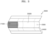
- the cigarette 20000 may include a tobacco rod 21000 and a filter rod 22000.
- the first portion described above with reference to FIGS. 1 and 2 may include the tobacco rod 21000, and the second portion may include the filter rod 22000.
- FIG. 3 illustrates that the filter rod 22000 includes a single segment.
- the filter rod 22000 is not limited thereto.
- the filter rod 22000 may include a plurality of segments.
- the filter rod 22000 may include a first segment configured to cool an aerosol and a second segment configured to filter a certain component included in the aerosol.
- the filter rod 22000 may further include at least one segment configured to perform other functions.
- the cigarette 2000 may be packaged using at least one wrapper 24000.
- the wrapper 24000 may have at least one hole through which external air may be introduced or internal air may be discharged.
- the cigarette 20000 may be packaged using one wrapper 24000.
- the cigarette 20000 may be doubly packaged using at least two wrappers 24000.
- the tobacco rod 21000 may be packaged using a first wrapper, and the filter rod 22000 may be packaged using a second wrapper.
- the tobacco rod 21000 and the filter rod 22000, which are respectively packaged using separate wrappers may be combined and packaged together using a third wrapper.
- each segment may be packaged using a separate wrapper.
- the entire cigarette 20000 including the plurality of segments, which are respectively packaged using the separate wrappers and which are coupled to each other may be re-packaged using another wrapper.
- the tobacco rod 21000 may include an aerosol generating material.
- the aerosol generating material may include at least one of glycerin, propylene glycol, ethylene glycol, dipropylene glycol, diethylene glycol, triethylene glycol, tetraethylene glycol, and oleyl alcohol, but it is not limited thereto.
- the tobacco rod 21000 may include other additives, such as flavors, a wetting agent, and/or organic acid.
- the tobacco rod 21000 may include a flavored liquid, such as menthol or a moisturizer, which is injected to the tobacco rod 21000.
- the tobacco rod 21000 may be manufactured in various forms.
- the tobacco rod 21000 may be formed as a sheet or a strand.
- the tobacco rod 21000 may be formed as a pipe tobacco, which is formed out of tiny bits cut from a tobacco sheet.
- the tobacco rod 21000 may be surrounded by a heat conductive material.
- the heat conductive material may be, but is not limited to, a metal foil such as aluminum foil.
- the heat conductive material surrounding the tobacco rod 21000 may uniformly distribute heat transmitted to the tobacco rod 21000, and thus, the heat conductivity applied to the tobacco rod may be increased and taste of the tobacco may be improved.
- the heat conductive material surrounding the tobacco rod 21000 may function as a susceptor heated by the induction heater.
- the tobacco rod 21000 may further include an additional susceptor, in addition to the heat conductive material surrounding the tobacco rod 21000.
- the filter rod 22000 may include a cellulose acetate filter. Shapes of the filter rod 22000 are not limited.
- the filter rod 22000 may include a cylinder-type rod or a tube-type rod having a hollow inside.
- the filter rod 22000 may include a recess-type rod.
- the filter rod 22000 includes a plurality of segments, at least one of the plurality of segments may have a different shape.
- the filter rod 22000 may be formed to generate flavors. For example, a flavoring liquid may be injected onto the filter rod 22000, or an additional fiber coated with a flavoring liquid may be inserted into the filter rod 22000.
- the filter rod 22000 may include at least one capsule 23000.
- the capsule 23000 may generate a flavor or aerosol.
- the capsule 23000 may have a configuration in which a liquid containing a flavoring material is wrapped with a film.
- the capsule 23000 may have a spherical or cylindrical shape, but is not limited thereto.
- the cooling segment may include a polymer material or a biodegradable polymer material.
- the cooling segment may include pure polylactic acid alone, but the material for forming the cooling segment is not limited thereto.
- the cooling segment may include a cellulose acetate filter having a plurality of holes.
- the cooling segment is not limited to the above-described example and is not limited as long as the cooling segment cools the aerosol.
- the cigarette 20000 may further include a front-end filter.
- the front-end filter may be located on a side of the tobacco rod 21000, which is the side not facing the filter rod 22000.
- the front-end filter may prevent the tobacco rod 21000 from being detached outwards and prevent a liquefied aerosol from flowing into the aerosol generating device 10000 ( FIGS. 1 and 2 ) from the tobacco rod 21000, during smoking.
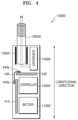
- FIG. 4 is a view illustrating an aerosol generating device including a rigid printed circuit board (PCB) and a flexible PCB according to an exemplary embodiment.
- PCB printed circuit board
- the aerosol generating device 10000 may include a plurality of PCBs.
- the aerosol generating device 10000 includes a main PCB 410, an auxiliary PCB 420, and a connecting PCB 430 that electrically connects the main PCB 410 to the auxiliary PCB 420.
- the main PCB 410 is located parallel to a longitudinal direction of the aerosol generating device 10000, and the auxiliary PCB 420 is located perpendicular to the longitudinal direction of the aerosol generating device 10000.
- the main PCB 410 is located parallel to the longitudinal direction of the aerosol generating device 10000 at a side of the battery 11000, and the auxiliary PCB 420 is located perpendicular to the longitudinal direction of the aerosol generating device 10000 between the heater 13000 (or the vaporizer 14000) and a battery 11000.
- the battery 11000 and the controller 12000 may be located in serial in the longitudinal direction of the aerosol generating device 10000, and the main PCB 410 may be located at a side of the battery 11000 and the controller 12000.
- the main PCB 410 may be located parallel to the longitudinal direction of the aerosol generating device 10000 over at least a part of the controller 12000 and the battery 11000.
- the heater 13000 and the vaporizer 14000 may be serially located in a direction perpendicular to the longitudinal direction of the aerosol generating device 10000.
- the auxiliary PCB 420 may be located facing at least one side of the heater 13000 and the vaporizer 14000.
- the auxiliary PCB 420 may be located perpendicular to the longitudinal direction of the aerosol generating device 10000 over at least a part of the vaporizer 14000 and the heater 13000.
- the auxiliary PCB 420 may be located between the controller 12000, and the heater 13000 and the vaporizer 14000.
- the connecting PCB 430 may be curved and may contact a portion of the main PCB 410 and a portion of the auxiliary PCB 420 to electrically connect the main PCB 410 to the auxiliary PCB 420.
- the connecting PCB 430 may contact a portion of a top surface or a bottom surface of each of the main PCB 410 and the auxiliary PCB 420.
- the connecting PCB 430 may contact an end portion of the main PCB 410 close to an insertion side and an end portion of the auxiliary PCB 420 adjacent to the end portion of the main PCB 410 close to the insertion side to electrically connect the main PCB 410 to the auxiliary PCB 420.
- the insertion side refers to a direction toward the portion of the aerosol generating device 10000 where the cigarette 2000 is inserted.
- the main PCB 410 and the auxiliary PCB 420 may be formed using a rigid material.
- the rigid material of the main PCB 410 and the auxiliary PCB 420 may be one of Flame Retardant-1 (FR-1), Flame Retardant-2 (FR-2), Flame Retardant-3 (FR-3), Flame Retardant-4 (FR-4), Composite Epoxy Material-1 (CEM-1), and Composite Epoxy Material-3 (CEM-3).
- FR-1 Flame Retardant-1
- FR-2 Flame Retardant-2
- FR-3 Flame Retardant-3
- FR-4 Flame Retardant-4
- CEM-1 Composite Epoxy Material-1
- CEM-3 Composite Epoxy Material-3
- Each of the main PCB 410 and the auxiliary PCB 420 may include an insulating layer and a conductive layer, and may be a build-up PCB in which the insulating layer and the conductive layer are alternately stacked.
- each of the main PCB 410 and the auxiliary PCB 420 may be a 6-layer PCB.
- the connecting PCB 430 is formed using a flexible material.
- the flexible material of the connecting PCB 430 may be polyimide. Because the connecting PCB 430 is located adjacent to the heater 13000 and/or the vaporizer 14000, a temperature of the connecting PCB 430 may increase to a high temperature during an operation of the aerosol generating device 10000. Because polyimide may withstand up to 400°C, degradation of reliability may be prevented when the connecting PCB 430 is made using polyimide. Also, PCB manufacturing costs may be reduced and assembly performance may be improved.
- the connecting PCB 430 may include a first insulating layer, a conductive layer formed on the first insulating layer, and a second insulating layer stacked on the conductive layer.
- the conductive layer may include copper and the first and second insulating layers may include polyimide, but the present disclosure is not limited thereto.
- the connecting PCB 430 includes a connecting area for connecting the main PCB 410 and the auxiliary PCB 420, and the connecting area may include a plating layer plated on the conductive layer exposed by peeling off the second insulating layer.
- the conductive layer formed out of copper may be exposed by peeling a portion of the second insulating layer formed out of polyimide, and the connecting area of the connecting PCB 430 may be formed by plating the exposed conductive layer with gold.
- the main PCB 410 and the auxiliary PCB 420 may be electrically connected to the connecting PCB 430 through the plating layer of the connecting area.
- the connecting area (i.e., the plating layer) of the connecting PCB 430 may be located on both end portions of the connecting PCB 430. That is, the end portions of the connecting PCB 430 may respectively contact the main PCB 410 and the auxiliary PCB 420, thereby electrically connecting the main PCB 410 to the auxiliary PCB 420.
- the heat capacity of the connecting PCB 430 may be increased by plating the copper layer exposed on both end portions of the connecting PCB 430 with gold, and thus, the connecting PCB 430 may be prevented from being overheated by the heater 13000 and/or the vaporizer 14000.
- a temperature of the auxiliary PCB 420 may increase to a high temperature during an operation of the aerosol generating device 10000.
- the auxiliary PCB 420 may be prevented from being overheated by attaching a heat dissipating plate to the auxiliary PCB 420 or using the auxiliary PCB 420 having a heat dissipating function.
- a heat dissipating material may include silicon, rubber, and gel.
- the single PCB may extend from one end to the other end in a longitudinal direction of the aerosol generating device 10000.
- FIG. 4 when a circuit of the aerosol generating device 10000 is configured by separating a PCB into the main PCB 410 and the auxiliary PCB 420, instead of configuring a circuit by using only a single PCB, an internal space of the aerosol generating device 10000 may be more efficiently used and thus a total size of the aerosol generating device 10000 may be reduced.
- the auxiliary PCB 420 may be a flexible PCB including a material such as polyimide.
- a material such as polyimide.
- FIG. 5 is a block diagram illustrating components connected to an auxiliary PCB according to an exemplary embodiment.
- an auxiliary PCB 500 may be electrically connected to a battery 510, a controller 520, a pressure sensor 530, a vaporizer 540, and a heater 550.
- the auxiliary PCB 500 may be electrically connected to other components in addition to the components (i.e., 510 through 550) of FIG. 5 .
- Some of the components (i.e., 510 through 550) of FIG. 5 may be omitted.
- the auxiliary PCB 500 may be electrically connected to the battery 510 and the controller 520.
- the controller 520 may be attached to, for example, the auxiliary PCB 500, and may be electrically connected to the auxiliary PCB 500.
- the battery 510 supplies power to operate components of an aerosol generating device, and the controller 520 is hardware for controlling an overall operation of the aerosol generating device.
- the pressure sensor 530 detects an inhalation pressure when a cigarette inserted into the aerosol generating device is inhaled.
- the pressure sensor 530 generates a signal by detecting an inhalation pressure that is the pressure of the air introduced from the outside during a user's operation (puff operation) of inhaling a cigarette.
- the pressure sensor 530 may be located in an airflow path in which the air introduced from the outside by the user's puff operation flows.
- the auxiliary PCB 500 may be electrically connected to the pressure sensor 530.
- Components of the vaporizer 540 may include, but are not limited to, a liquid storage, a liquid transmitting device, and a heating element.
- a liquid composition stored in the liquid storage may be a liquid including a tobacco-containing material and/or a non-tobacco material.
- the liquid transmitting device may include wicks such as porous ceramics and may transmit the liquid composition in the liquid storage to the heating element.
- the heating element heats the liquid composition transmitted by the liquid transmitting device.
- the auxiliary PCB 500 may be electrically connected to the vaporizer 540.
- the heater 550 may heat an aerosol generating material included in the cigarette.
- the heater 550 may be located outside or inside the cigarette.
- the heater 550 may include a tube-type heating element, a plate-type heating element, a needle-type heating element, or a rod-type heating element, and may heat the inside or the outside of the cigarette according to a shape of the heating element.
- the auxiliary PCB 500 may be electrically connected to the heater 550.
- FIG. 6 is a block diagram illustrating components connected to a main PCB according to an exemplary embodiment.
- a main PCB 600 may be electrically connected to a battery 610, a controller 620, a temperature sensor 630, an antenna 640, and an interface 650.
- the controller 620 may be attached to, for example, the main PCB 600 and may be electrically connected to the main PCB 600.
- the main PCB 600 may be electrically connected to other components in addition to the components (610 through 650) of FIG. 6 .
- Some of the components (610 through 650) of FIG. 6 may be omitted.
- the temperature sensor 630 may detect a temperature of a heater that heats a cigarette. In an exemplary embodiment, a temperature of the heater may be detected by measuring a resistance value of the temperature sensor 630.
- the temperature sensor 630 may be located on a side wall or a bottom wall of an accommodation passage in which the cigarette is accommodated. However, a temperature sensing method and a position of the temperature sensor 630 are not limited thereto.
- the main PCB 600 may be electrically connected to the temperature sensor 630.
- the antenna 640 may communicate with the outside.
- the antenna 640 may be a Bluetooth ® antenna for wireless communication.
- the main PCB 600 may be electrically connected to the antenna 640.
- the interface 650 may include a display or a lamp that outputs visual information, a motor that outputs tactile information, and a speaker that outputs sound information.
- the main PCB 600 may be electrically connected to the interface 650.
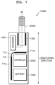
- FIG. 7 is a view illustrating an aerosol generating device including a rigid-flexible PCB according to a second aspect of the invention.
- the aerosol generating device 10000 includes a rigid-flexible PCB 720.
- the rigid-flexible PCB 720 is a single PCB.
- the rigid-flexible PCB 720 includes a first rigid portion 711a, a second rigid portion 711b, and a flexible portion 712.
- the first rigid portion 711a is located parallel to a longitudinal direction of the aerosol generating device 10000
- the second rigid portion 711b is located perpendicular to the longitudinal direction of the aerosol generating device 10000.
- the flexible portion 712 is curved and connects the first rigid portion 711a to the second rigid portion 711b.
- the first rigid portion 711a is located parallel to the longitudinal direction of the aerosol generating device 10000 at a side of the battery 11000, and the second rigid portion 711b is located perpendicular to the longitudinal direction of the aerosol generating device 10000 between the heater 13000 (or the vaporizer 14000) and the battery 11000.
- the battery 11000 and the controller 12000 may be serially arranged in the longitudinal direction of the aerosol generating device 10000, and the first rigid portion 711a may be located at a side of the battery 11000 and the controller 12000.
- the first rigid portion 711a may be located parallel to the longitudinal direction of the aerosol generating device 10000 over at least a part of the battery 11000 and the controller 12000.
- the heater 13000 and the vaporizer 14000 may be located parallel to a direction perpendicular to the longitudinal direction of the aerosol generating device 10000, and the second rigid portion 711b may be located at at least one side of the heater 13000 and the vaporizer 14000.
- the second rigid portion 711b may be located parallel to the longitudinal direction of the aerosol generating device 10000 over at least a part of the heater 13000 and the vaporizer 14000, and the second rigid portion 711b may be located between the heater 13000 and the vaporizer 14000, and the controller 12000.
- a rigid material for making the first rigid portion 711a and the second rigid portion 711b may include one of Flame Retardant-1 (FR-1), Flame Retardant-2 (FR-2), Flame Retardant-3 (FR-3), Flame Retardant-4 (FR-4), Composite Epoxy Material-1 (CEM-1), and Composite Epoxy Material-3 (CEM-3).
- FR-1 Flame Retardant-1
- FR-2 Flame Retardant-2
- FR-3 Flame Retardant-3
- FR-4 Flame Retardant-4
- CEM-1 Composite Epoxy Material-1
- CEM-3 Composite Epoxy Material-3
- a flexible material of the flexible portion 712 may be polyimide. Because the flexible portion 712 is located adjacent to the heater 13000 and/or the vaporizer 14000, a temperature of the flexible portion 712 may increase to a high temperature during an operation of the aerosol generating device 10000. Because polyimide may withstand up to 400°C, reliability degradation may be prevented when the flexible portion 712 is made using polyimide. Also, PCB manufacturing costs may be reduced and assembly performance may be improved.
- a temperature of the second rigid portion 711b may increase to a high temperature during an operation of the aerosol generating device 10000.
- a heat dissipating plate may include silicon, rubber, and gel.
- an internal space of the aerosol generating device 10000 may be more efficiently used and thus a total size of the aerosol generating device 10000 may be reduced.
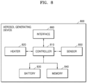
- FIG. 8 is a block diagram illustrating a hardware configuration of an aerosol generating device.
- an aerosol generating device 800 may include a controller 810, a heater 820, a battery 830, a memory 840, a sensor 850, and an interface 860.
- the heater 820 may be electrically heated by power supplied from the battery 830 under the control of the controller 810.
- the heater 820 may be located inside or outside the cigarette. Accordingly, the heater 820 that is heated may increase a temperature of an aerosol generating material in the cigarette.
- the heater 820 may be any heater as long as it may be inserted into the cigarette or may heat the outside of the cigarette. Also, the heater 820 may be heated partially.
- the heater 820 may be an electro-resistive heater.
- the heater 820 may include an electrically conductive track, and the heater 820 may be heated as current flows through the electrically conductive track.
- a surface temperature of the heater 820 may increase to 400°C or more.
- the surface temperature of the heater 820 may increase to about 350°C before 15 seconds after power supply to the heater 820 starts.
- a separate temperature detecting sensor may be provided around the heater 820 of the aerosol generating device.
- a temperature detecting sensor may not be provided around the heater 820, and the heater 820 may function as a temperature detecting sensor. Otherwise, the heater 820 functions as a temperature detecting sensor, and a separate temperature detecting sensor may be further provided around the heater 820.
- the heater 820 may include at least one electrically conductive track for emitting heat and detecting a temperature. Also, the heater 820 may include a first electrically conductive track for emitting heat and a second electrically conductive track for detecting a temperature.
- a resistance R may be determined.
- a temperature T of the second electrically conductive track may be determined by using Equation 1.
- Equation 1 R denotes a current resistance value of the second electrically conductive track
- R0 denotes a resistance value at a temperature of T0 (e.g., 0°C)
- ⁇ denotes a resistance temperature coefficient of the second electrically conductive track.
- a conductive material e.g., a metal
- ⁇ may be predetermined according to the conductive material included in the second electrically conductive track. Accordingly, when the resistance R of the second electrically conductive track is determined, the temperature T of the second electrically conductive track may be calculated by using Equation 1.
- the heater 820 may include at least one electrically conductive track (e.g., the first electrically conductive track and the second electrically conductive track).
- the heater 820 may include, but is not limited to, two first electrically conductive tracks and one or two second electrically conductive tracks.
- the electrically conductive track includes an electro-resistive material.
- the electrically conductive track may be formed out of a metal material.
- the electrically conductive track may be formed out of an electrically conductive ceramic material, carbon, a metal alloy, or a combination of a ceramic material and a metal.
- both the electrically conductive track and the temperature detecting sensor for functioning as a temperature detecting sensor may be provided around the heater 820.
- the controller 810 is hardware that controls an overall operation of the aerosol generating device 800.
- the controller 810 is an integrated circuit including a processing unit such as a microprocessor or a microcontroller.
- the controller 810 analyzes a result sensed by the sensor 850 and controls subsequent processes to be performed.
- the controller 810 may start or stop power supply from the battery 830 to the heater 820 according to the sensed result. Also, the controller 810 may control the amount of power supplied to the heater 820 and the time when power is supplied to the heater 820 so that the heater 820 is heated to a predetermined temperature or maintained at an appropriate temperature. Furthermore, the controller 810 may process various pieces of input information and output information of the interface 860.
- the controller 810 may count the number of times a user smokes by using the aerosol generating device 800 and may control related functions of the aerosol generating device 800 to limit the user's smoking according to a counting result.
- the memory 840 that is hardware for storing various pieces of data processed by the aerosol generating device 800 may store data processed and to be processed by the controller 810.
- the memory 840 may be any of various memories such as random-access memory (e.g., dynamic random-access memory (DRAM) or static random-access memory (SRAM)), read-only memory (ROM), or electrically erasable programmable read-only memory (EEPROM).
- DRAM dynamic random-access memory
- SRAM static random-access memory
- ROM read-only memory
- EEPROM electrically erasable programmable read-only memory
- the memory 840 may store data about the user's smoking patterns such as a smoking time and the number of times the user smokes. Also, data related to a change in a reference temperature value when the cigarette is accommodated in an accommodation passage may be stored in the memory 840.
- the battery 830 supplies power used for the aerosol generating device 800 to operate. That is, the battery 830 may supply power so that the heater 820 is heated. Also, the battery 830 may supply power required for operations of other hardware components provided in the aerosol generating device 800, such as the controller 810, the sensor 850, and the interface 860.
- the battery 830 may be a lithium iron phosphate (LiFePO4) battery, but the present disclosure is not limited thereto.
- the battery 830 may be a lithium cobalt oxide (LiCoO2) battery, or a lithium titanate battery.
- the battery 830 may be a rechargeable battery or a disposable battery.
- the sensor 850 may include various types of sensors such as a puff detecting sensor (a temperature detecting sensor, a flow detecting sensor, a position detecting sensor, etc.), a cigarette insertion detecting sensor, and a temperature detecting sensor of the heater 820.
- a result sensed by the sensor 850 may be transmitted to the controller 810, and the controller 810 may control, according to the sensed result, the aerosol generating device 800 to perform various functions such as controlling a temperature of the heater 820, limiting smoking, determining whether the cigarette is inserted, and displaying an alarm.
- the interface 860 may include various interfacing devices such as a display or a lamp for outputting visual information, a motor for outputting tactile information, a speaker for outputting sound information, terminals for receiving charging power or performing data communication with input/output (I/O) interfacing devices (e.g., buttons or a touchscreen) for receiving information input from the user or outputting information to the user, and a communication interfacing module for performing wireless communication (e.g., Wi-Fi, Wi-Fi Direct, Bluetooth, and Near-Field Communication (NFC)) with an external device.
- I/O input/output
- a communication interfacing module for performing wireless communication (e.g., Wi-Fi, Wi-Fi Direct, Bluetooth, and Near-Field Communication (NFC)) with an external device.
- the aerosol generating device 800 may be implemented by selecting only some of the various interfacing devices.
Landscapes
- Engineering & Computer Science (AREA)
- Physics & Mathematics (AREA)
- Microelectronics & Electronic Packaging (AREA)
- Chemical Kinetics & Catalysis (AREA)
- General Chemical & Material Sciences (AREA)
- Chemical & Material Sciences (AREA)
- Health & Medical Sciences (AREA)
- General Engineering & Computer Science (AREA)
- Optics & Photonics (AREA)
- General Physics & Mathematics (AREA)
- Electromagnetism (AREA)
- General Health & Medical Sciences (AREA)
- Life Sciences & Earth Sciences (AREA)
- Biomedical Technology (AREA)
- Toxicology (AREA)
- Hematology (AREA)
- Animal Behavior & Ethology (AREA)
- Public Health (AREA)
- Veterinary Medicine (AREA)
- Botany (AREA)
- Heart & Thoracic Surgery (AREA)
- Anesthesiology (AREA)
- Pulmonology (AREA)
- Bioinformatics & Cheminformatics (AREA)
- Agronomy & Crop Science (AREA)
- Resistance Heating (AREA)
- Human Computer Interaction (AREA)
- Computer Networks & Wireless Communication (AREA)
- Containers And Packaging Bodies Having A Special Means To Remove Contents (AREA)
Claims (11)
- Dispositif de production d'aérosol (10000) comportant :au moins un élément chauffant (13000) configuré pour produire un aérosol en chauffant une matière de production d'aérosol ;une batterie (11000) configurée pour fournir de l'énergie afin de chauffer le au moins un élément chauffant (13000) ;une commande (12000) ; etune carte à circuit imprimé, PCB, principale (410, 600) et une PCB auxiliaire (420, 500) qui sont formées d'un matériau rigide,dans lequel la PCB principale (410, 600) est placée parallèlement à une direction longitudinale du dispositif de production d'aérosol (10000), et la PCB auxiliaire (420, 500) est placée perpendiculairement à la direction longitudinale du dispositif de production d'aérosol (13000), etdans lequel la PCB principale (410, 600) et la PCB auxiliaire (420, 500) sont électriquement connectées l'une à l'autre via une PCB de connexion (430) formée d'un matériau souple,dans lequel la PCB principale (410, 600) est placée parallèlement à la direction longitudinale du dispositif de production d'aérosol (10000) sur un côté d'au moins un élément parmi la batterie (11000) et la commande (12000), etla PCB auxiliaire (420, 500) est placée perpendiculairement à la direction longitudinale du dispositif de production d'aérosol (10000) entre le au moins un élément chauffant (13000) et la batterie (11000).
- Dispositif de production d'aérosol selon la revendication 1, dans lequel le au moins un élément chauffant (13000) comporte :un élément chauffant (13000) configuré pour chauffer la matière de production d'aérosol incluse dans une cigarette (20000) ; etun vaporisateur (14000) configuré pour produire un aérosol en chauffant une composition liquide,dans lequel la PCB auxiliaire (4420, 500) est électriquement connectée à l'élément chauffant (13000) et au vaporisateur (14000).
- Dispositif de production d'aérosol selon la revendication 1, comportant en outre un capteur de pression (530) configuré pour détecter une pression d'inhalation qui est générée lorsqu'une cigarette (20000) insérée dans le dispositif de production d'aérosol (10000) est inhalée,
dans lequel la PCB auxiliaire (420, 500) est électriquement connectée au capteur de pression (530). - Dispositif de production d'aérosol selon la revendication 1, dans lequel la PCB principale (410, 600) est électriquement connectée à un au moins un élément parmi un capteur de température (630) destiné à détecter une température du au moins un élément chauffant (13000), une antenne (640) de communication sans fil, et une interface (650) destinée à indiquer un état de fonctionnement du dispositif de production d'aérosol (10000).
- Dispositif de production d'aérosol selon la revendication 1, dans lequel le matériau rigide de la PCB principale (410, 600) et de la PCB auxiliaire (420, 500) est l'ignifugeant FR-4 (Flame Retardant-4) et le matériau souple de la PCB de connexion est un polyimide.
- Dispositif de production d'aérosol selon la revendication 1, dans lequel une plaque de dissipation de chaleur est fixée à la PCB auxiliaire (420, 500) pour empêcher une mise en surchauffe de la PCB auxiliaire (420, 500) par le au moins un élément chauffant (13000).
- Dispositif de production d'aérosol selon la revendication 1, dans lequella PCB de connexion (430) comporte une première couche isolante, une couche conductrice formée sur la première couche isolante, et une seconde couche isolante empilée sur la couche conductrice,la PCB de connexion (430) comporte une zone de connexion pour connecter la PCB principale à la PCB auxiliaire, et la zone de connexion comporte une couche de placage plaquée sur la couche conductrice exposée en détachant par pelage la seconde couche isolante, etla PCB principale (410, 600) et la PCB auxiliaire (420, 500) sont connectées à la PCB de connexion (430) à travers la couche de placage.
- Dispositif de production d'aérosol selon la revendication 7, dans lequelchaque couche parmi la première couche isolante et la seconde couche isolante comporte un polyimide,la couche conductrice comporte du cuivre, etla couche de plaquage comporte de l'or.
- Dispositif de production d'aérosol (10000) comportant :au moins un élément chauffant (13000) configuré pour produire un aérosol en chauffant une matière de production d'aérosol ;une batterie (11000) configurée pour fournir de l'énergie afin de chauffer le au moins un élément chauffant (13000) ;une commande (12000) ; etune carte à circuit imprimé, PCB, rigide-souple (720),caractérisé en ce qu'une première partie rigide (711a) de la PCB rigide-souple (720) est placée parallèlement à une direction longitudinale du dispositif de production d'aérosol (10000), une seconde partie rigide (711b) est placée perpendiculairement à la direction longitudinale du dispositif de production d'aérosol (10000), et une partie souple (712) est incurvée et connecte la première partie rigide (711a) à la seconde partie rigide (711b),dans lequel la première partie rigide (711a) est placée parallèlement à la direction longitudinale du dispositif de production d'aérosol (10000) sur un côté de la batterie (11000), et la seconde partie rigide (711b) est placée perpendiculairement à la direction longitudinale du dispositif de production d'aérosol (10000) entre l'élément chauffant (13000) et la batterie (11000) ou entre un vaporisateur (14000) et la batterie (11000).
- Dispositif production d'aérosol selon la revendication 9, dans lequel un matériau de la première partie rigide (711a) et de la seconde partie rigide (711b) de la PCB rigide-souple (720) est l'ignifugeant FR-4 (Flame-Retardant 4) et un matériau de la partie souple (712) est un polyimide.
- Dispositif de production d'aérosol selon la revendication 9, dans lequel une plaque de dissipation de chaleur est fixée à la PCB rigide-souple (720) pour empêcher une mise en surchauffe de la PCB rigide-souple (720) par le au moins un élément chauffant (13000).
Applications Claiming Priority (3)
| Application Number | Priority Date | Filing Date | Title |
|---|---|---|---|
| KR20170142578 | 2017-10-30 | ||
| KR1020180059580A KR102074930B1 (ko) | 2017-10-30 | 2018-05-25 | 에어로졸 생성 장치 |
| PCT/KR2018/012676 WO2019088559A2 (fr) | 2017-10-30 | 2018-10-25 | Dispositif de génération d'aérosol |
Publications (3)
| Publication Number | Publication Date |
|---|---|
| EP3704964A2 EP3704964A2 (fr) | 2020-09-09 |
| EP3704964A4 EP3704964A4 (fr) | 2021-09-15 |
| EP3704964B1 true EP3704964B1 (fr) | 2025-06-18 |
Family
ID=66332896
Family Applications (1)
| Application Number | Title | Priority Date | Filing Date |
|---|---|---|---|
| EP18872432.2A Active EP3704964B1 (fr) | 2017-10-30 | 2018-10-25 | Dispositif de génération d'aérosol |
Country Status (5)
| Country | Link |
|---|---|
| US (1) | US11528936B2 (fr) |
| EP (1) | EP3704964B1 (fr) |
| JP (1) | JP6840289B2 (fr) |
| CN (1) | CN111050579B (fr) |
| WO (1) | WO2019088559A2 (fr) |
Families Citing this family (34)
| Publication number | Priority date | Publication date | Assignee | Title |
|---|---|---|---|---|
| EP4010053A1 (fr) * | 2019-08-06 | 2022-06-15 | Nicoventures Trading Limited | Système de fourniture d'aérosol hybride |
| CN114126430B (zh) | 2019-08-08 | 2025-02-18 | 日本烟草国际股份有限公司 | 气雾剂发生装置和制造方法 |
| KR20210039199A (ko) | 2019-10-01 | 2021-04-09 | 주식회사 케이티앤지 | 디스플레이를 포함하는 에어로졸 생성 장치 |
| JP7650875B2 (ja) | 2019-10-17 | 2025-03-25 | フィリップ・モーリス・プロダクツ・ソシエテ・アノニム | 改善された閉鎖手段を有する充電器およびエアロゾル発生システム |
| EP4044857B1 (fr) | 2019-10-17 | 2023-11-29 | Philip Morris Products S.A. | Chargeur et système de génération d'aérosols doté d'un couvercle à composants multiples |
| US12256787B2 (en) | 2019-10-17 | 2025-03-25 | Philip Morris Products S.A. | Charger and aerosol-generating system with rotatable cover |
| US11589610B2 (en) | 2019-12-15 | 2023-02-28 | Shaheen Innovations Holding Limited | Nicotine delivery device having a mist generator device and a driver device |
| KR102354965B1 (ko) | 2020-02-13 | 2022-01-24 | 주식회사 케이티앤지 | 에어로졸 생성 장치 및 그의 동작 방법 |
| JP6888138B1 (ja) * | 2020-02-25 | 2021-06-16 | 日本たばこ産業株式会社 | エアロゾル吸引器の電源ユニット |
| JP6888137B1 (ja) * | 2020-02-25 | 2021-06-16 | 日本たばこ産業株式会社 | エアロゾル吸引器の電源ユニット及びエアロゾル吸引器 |
| KR102538129B1 (ko) | 2020-07-03 | 2023-05-30 | 주식회사 케이티앤지 | 히터 조립체, 및 에어로졸 생성 시스템 |
| EP4192282A1 (fr) * | 2020-08-10 | 2023-06-14 | JT International SA | Absorption des chocs dans un dispositif de génération d'aérosol portatif |
| CA3185862A1 (fr) * | 2020-08-10 | 2022-02-17 | Kyle ADAIR | Dispositif de generation d'aerosol a carte de circuit imprime emboitee et flexible |
| JP6834053B1 (ja) * | 2020-09-30 | 2021-02-24 | 日本たばこ産業株式会社 | エアロゾル生成装置の電源ユニット |
| JP6890203B1 (ja) | 2020-09-30 | 2021-06-18 | 日本たばこ産業株式会社 | エアロゾル生成装置の電源ユニット |
| JP7019785B1 (ja) | 2020-11-20 | 2022-02-15 | 日本たばこ産業株式会社 | エアロゾル生成装置 |
| JP6915142B1 (ja) * | 2020-11-20 | 2021-08-04 | 日本たばこ産業株式会社 | エアロゾル生成装置の電源ユニット |
| JP6922062B1 (ja) * | 2020-11-20 | 2021-08-18 | 日本たばこ産業株式会社 | エアロゾル生成装置の電源ユニット |
| JP7159410B2 (ja) * | 2020-11-20 | 2022-10-24 | 日本たばこ産業株式会社 | エアロゾル生成装置 |
| JP6915143B1 (ja) * | 2020-11-20 | 2021-08-04 | 日本たばこ産業株式会社 | エアロゾル生成装置の電源ユニット |
| EP4017213A1 (fr) * | 2020-12-16 | 2022-06-22 | JT International SA | Carte de circuit imprimé pour dispositif de génération d'aérosol |
| EP4338623A4 (fr) * | 2021-05-10 | 2025-07-16 | Japan Tobacco Inc | Unité alimentation électrique pour dispositif de génération d'aérosol |
| JP7104262B1 (ja) | 2021-05-10 | 2022-07-20 | 日本たばこ産業株式会社 | エアロゾル発生装置の電源ユニット |
| JP7104868B1 (ja) | 2021-05-10 | 2022-07-21 | 日本たばこ産業株式会社 | エアロゾル発生装置 |
| WO2022239343A1 (fr) * | 2021-05-10 | 2022-11-17 | 日本たばこ産業株式会社 | Unité de circuit pour dispositif de génération d'aérosol, et dispositif de génération d'aérosol |
| JP7767025B2 (ja) | 2021-05-10 | 2025-11-11 | 日本たばこ産業株式会社 | エアロゾル生成装置の電源ユニット |
| KR102713417B1 (ko) * | 2021-05-14 | 2024-10-07 | 주식회사 케이티앤지 | 에어로졸 생성 물품 및 이를 포함하는 에어로졸 생성 장치 |
| KR102673338B1 (ko) * | 2021-08-06 | 2024-06-07 | 주식회사 케이티앤지 | 에어로졸 생성 장치 |
| KR102886544B1 (ko) * | 2021-11-25 | 2025-11-13 | 주식회사 케이티앤지 | 에어로졸 생성장치 |
| JP7389933B2 (ja) * | 2021-12-10 | 2023-11-30 | 日本たばこ産業株式会社 | エアロゾル生成装置 |
| WO2023105768A1 (fr) | 2021-12-10 | 2023-06-15 | 日本たばこ産業株式会社 | Unité alimentation électrique pour dispositif de génération d'aérosol |
| KR20240095355A (ko) * | 2021-12-10 | 2024-06-25 | 니뽄 다바코 산교 가부시키가이샤 | 에어로졸 생성 장치의 전원 유닛 |
| WO2023112182A1 (fr) * | 2021-12-15 | 2023-06-22 | 日本たばこ産業株式会社 | Inhalateur d'arôme |
| US12550942B2 (en) | 2022-09-19 | 2026-02-17 | Altria Client Services Llc | Session control system |
Family Cites Families (235)
| Publication number | Priority date | Publication date | Assignee | Title |
|---|---|---|---|---|
| JPS6215793A (ja) | 1985-07-10 | 1987-01-24 | 三菱油化株式会社 | 可撓性ヒ−タ |
| US5093894A (en) | 1989-12-01 | 1992-03-03 | Philip Morris Incorporated | Electrically-powered linear heating element |
| US5408574A (en) | 1989-12-01 | 1995-04-18 | Philip Morris Incorporated | Flat ceramic heater having discrete heating zones |
| US5348027A (en) | 1991-02-14 | 1994-09-20 | R. J. Reynolds Tobacco Company | Cigarette with improved substrate |
| US5665262A (en) | 1991-03-11 | 1997-09-09 | Philip Morris Incorporated | Tubular heater for use in an electrical smoking article |
| US5388594A (en) | 1991-03-11 | 1995-02-14 | Philip Morris Incorporated | Electrical smoking system for delivering flavors and method for making same |
| US5505214A (en) | 1991-03-11 | 1996-04-09 | Philip Morris Incorporated | Electrical smoking article and method for making same |
| US5692525A (en) | 1992-09-11 | 1997-12-02 | Philip Morris Incorporated | Cigarette for electrical smoking system |
| JPH0673784U (ja) | 1993-03-23 | 1994-10-18 | マルイ工業株式会社 | 表示パネル |
| US5555476A (en) | 1993-08-30 | 1996-09-10 | Toray Industries, Inc. | Microlens array sheet for a liquid crystal display, method for attaching the same and liquid crystal display equipped with the same |
| JPH0772809A (ja) | 1993-09-02 | 1995-03-17 | Toray Ind Inc | 液晶ディスプレイ用マイクロレンズアレイシート、およびそれを用いた液晶ディスプレイ |
| CR4906A (es) | 1993-09-10 | 1994-09-09 | Philip Morris Prod | Sistema electrico de fumar para distribuir sabores y metodopara su fabricacion |
| AR002035A1 (es) | 1995-04-20 | 1998-01-07 | Philip Morris Prod | Un cigarrillo, un cigarrillo y encendedor adaptados para cooperar entre si, un metodo para mejorar la entrega de aerosol de un cigarrillo, un material continuo de tabaco, un cigarrillo operativo, un metodo para manufacturar un material continuo, el material asi obtenido, un calentador, un metodo para formar un calentador y un sistema electrico para fumar |
| AU695608B2 (en) | 1995-06-07 | 1998-08-20 | Toyoda Gosei Co. Ltd. | Light-driven display device |
| JPH0975058A (ja) | 1995-09-18 | 1997-03-25 | Masaya Nagai | ニコチン喫気器 |
| JP3553245B2 (ja) | 1995-12-06 | 2004-08-11 | 本田技研工業株式会社 | 直接メタノール型燃料電池 |
| DE69632550T2 (de) | 1995-12-06 | 2005-05-25 | Honda Giken Kogyo K.K. | Direkte Methanol-Brennstoffzelle |
| JPH09228919A (ja) | 1996-02-22 | 1997-09-02 | Keehin:Kk | エアアシスト電磁式燃料噴射弁 |
| JPH1037781A (ja) | 1996-07-24 | 1998-02-10 | Suzuki Motor Corp | 内燃機関用吸気管圧力センサの取付構造 |
| US5878752A (en) | 1996-11-25 | 1999-03-09 | Philip Morris Incorporated | Method and apparatus for using, cleaning, and maintaining electrical heat sources and lighters useful in smoking systems and other apparatuses |
| US5902501A (en) | 1997-10-20 | 1999-05-11 | Philip Morris Incorporated | Lighter actuation system |
| BR0109685B1 (pt) | 2000-03-23 | 2013-07-23 | sistema de fumo elÉtrico e mÉtodo para fabricaÇço de cigarro para sistema de fumo elÉtrico | |
| KR200203233Y1 (ko) | 2000-06-19 | 2000-11-15 | 최성문 | 휴대용 권련 저장구 |
| US6615840B1 (en) | 2002-02-15 | 2003-09-09 | Philip Morris Incorporated | Electrical smoking system and method |
| US6803545B2 (en) | 2002-06-05 | 2004-10-12 | Philip Morris Incorporated | Electrically heated smoking system and methods for supplying electrical power from a lithium ion power source |
| US6810883B2 (en) | 2002-11-08 | 2004-11-02 | Philip Morris Usa Inc. | Electrically heated cigarette smoking system with internal manifolding for puff detection |
| JP3898118B2 (ja) | 2002-12-05 | 2007-03-28 | シンワ測定株式会社 | 温度検知機能を有する面状発熱装置の製造方法 |
| US7082825B2 (en) | 2002-12-27 | 2006-08-01 | Yamatake Corporation | Smoking device including a flowmeter |
| JP3975440B2 (ja) | 2002-12-27 | 2007-09-12 | 株式会社山武 | 流量計および喫煙装置 |
| US6803550B2 (en) | 2003-01-30 | 2004-10-12 | Philip Morris Usa Inc. | Inductive cleaning system for removing condensates from electronic smoking systems |
| KR100750586B1 (ko) | 2003-12-26 | 2007-08-20 | 한국전자통신연구원 | 미소유체 가열 시스템 |
| CA2552895A1 (fr) | 2004-01-16 | 2005-07-28 | Mitsubishi Cable Industries Ltd. | Prehension a manche presentant un element chauffant |
| JP4447929B2 (ja) | 2004-01-16 | 2010-04-07 | 三菱電線工業株式会社 | ハンドルグリップ用発熱体 |
| CN2719043Y (zh) | 2004-04-14 | 2005-08-24 | 韩力 | 雾化电子烟 |
| JP2006292620A (ja) | 2005-04-13 | 2006-10-26 | Shibaura Electronics Co Ltd | 傍熱形サーミスタ |
| US20060267614A1 (en) | 2005-05-24 | 2006-11-30 | Youn-Seob Lee | Ceramic heater |
| KR100782063B1 (ko) | 2005-05-24 | 2007-12-04 | 주식회사 스마텍 | 세라믹 히터 |
| KR100560332B1 (ko) | 2005-06-01 | 2006-03-14 | 삼성광주전자 주식회사 | 집진통 고정/분리 장치 및 이를 구비하는 사이클론집진장치 |
| US20070074734A1 (en) | 2005-09-30 | 2007-04-05 | Philip Morris Usa Inc. | Smokeless cigarette system |
| JP2007101639A (ja) | 2005-09-30 | 2007-04-19 | Dainippon Printing Co Ltd | 画像表示装置用フィルタおよびその製造方法 |
| CN100581398C (zh) | 2006-02-27 | 2010-01-20 | 何文天 | 可自动弹出烟支的环保型烟盒 |
| US7726320B2 (en) | 2006-10-18 | 2010-06-01 | R. J. Reynolds Tobacco Company | Tobacco-containing smoking article |
| CA2683884C (fr) | 2007-04-18 | 2012-10-30 | Japan Tobacco Inc. | Outil pour fumer |
| WO2009044716A1 (fr) | 2007-10-01 | 2009-04-09 | Koha Co., Ltd. | Dispositif d'émission de lumière |
| CN101324490B (zh) | 2008-07-25 | 2010-08-04 | 北京汇丰隆生物科技发展有限公司 | 一种大流量气溶胶采样装置 |
| TW201023769A (en) | 2008-10-23 | 2010-07-01 | Japan Tobacco Inc | Non-burning type flavor inhalation article |
| AT507187B1 (de) | 2008-10-23 | 2010-03-15 | Helmut Dr Buchberger | Inhalator |
| EP2201850A1 (fr) | 2008-12-24 | 2010-06-30 | Philip Morris Products S.A. | Article incluant des informations d'identification à utiliser dans un système de fumée chauffé thermiquement |
| CN101518361B (zh) | 2009-03-24 | 2010-10-06 | 北京格林世界科技发展有限公司 | 高仿真电子烟 |
| JP2010266425A (ja) | 2009-04-15 | 2010-11-25 | Toyota Motor Corp | 水素圧力センサ |
| EP2253233A1 (fr) | 2009-05-21 | 2010-11-24 | Philip Morris Products S.A. | Système de fumage chauffé électriquement |
| RU2529387C2 (ru) | 2009-08-07 | 2014-09-27 | Кайнд Консьюмер Лимитед | Ингалятор |
| KR200460461Y1 (ko) | 2009-09-30 | 2012-05-25 | 주식회사 손엔 | 기화 흡입 장치용 충전 장치 |
| EP2319334A1 (fr) | 2009-10-27 | 2011-05-11 | Philip Morris Products S.A. | Système de fumage ayant une partie de stockage de liquide |
| EP2316286A1 (fr) | 2009-10-29 | 2011-05-04 | Philip Morris Products S.A. | Système de fumage chauffé électriquement doté d'un chauffage amélioré |
| EP2327318A1 (fr) | 2009-11-27 | 2011-06-01 | Philip Morris Products S.A. | Système de fumage chauffé électriquement doté d'un chauffage interne ou externe |
| EP2340729A1 (fr) | 2009-12-30 | 2011-07-06 | Philip Morris Products S.A. | Chauffage amélioré pour système de génération d'aérosol chauffé électriquement |
| EP2340730A1 (fr) | 2009-12-30 | 2011-07-06 | Philip Morris Products S.A. | Chauffage formé pour système de génération d'aérosol |
| KR20110008931U (ko) * | 2010-03-12 | 2011-09-20 | 주식회사 손엔 | 기화 흡입 장치 |
| CN201657047U (zh) | 2010-03-23 | 2010-11-24 | 国基电子(上海)有限公司 | 移动电话 |
| CN102970885B (zh) | 2010-04-30 | 2015-05-20 | 洛艾克有限公司 | 电子吸烟设备 |
| KR101012472B1 (ko) | 2010-07-15 | 2011-02-08 | 양재성 | 집광 표지판 |
| KR101239080B1 (ko) | 2010-09-01 | 2013-03-06 | (주)제로스인터내셔널 | 음이온 발생기를 내장한 핸디형 네뷸라이져 |
| KR20120050568A (ko) | 2010-11-11 | 2012-05-21 | (주)데캉코리아 | 다기능 전자담배 |
| EP2460422A1 (fr) | 2010-12-03 | 2012-06-06 | Philip Morris Products S.A. | Système de génération d'aérosol avec prévention de fuite de condensats |
| EP2460423A1 (fr) * | 2010-12-03 | 2012-06-06 | Philip Morris Products S.A. | Système générateur d'aérosol à chauffage électrique avec une commande du chauffage améliorée |
| EP2460424A1 (fr) | 2010-12-03 | 2012-06-06 | Philip Morris Products S.A. | Système de génération d'aérosol doté de prévention de fuites |
| KR101057774B1 (ko) | 2010-12-13 | 2011-08-19 | 신종수 | 전자담배 |
| KR20120007263U (ko) | 2011-04-13 | 2012-10-23 | (주)데캉코리아 | 카트리지 일체형 전자담배 |
| US9347644B2 (en) | 2011-04-22 | 2016-05-24 | Sharp Kabushiki Kaisha | Lens and light source unit |
| KR20120008751U (ko) | 2011-06-13 | 2012-12-24 | 이영찬 | 전자담배 |
| KR101062248B1 (ko) | 2011-06-20 | 2011-09-05 | 신종수 | 전자담배 |
| US8528569B1 (en) | 2011-06-28 | 2013-09-10 | Kyle D. Newton | Electronic cigarette with liquid reservoir |
| WO2013007020A1 (fr) | 2011-07-12 | 2013-01-17 | Liu Qiuming | Système électronique pour tabac blond |
| CN103732280B (zh) | 2011-08-19 | 2016-01-06 | 日本烟草产业株式会社 | 气溶胶吸引器 |
| KR101289032B1 (ko) | 2011-09-20 | 2013-07-23 | 서울과학기술대학교 산학협력단 | 자동 점화장치가 구비된 담배 케이스 |
| AT511344B1 (de) | 2011-10-21 | 2012-11-15 | Helmut Dr Buchberger | Inhalatorkomponente |
| PT2770859T (pt) | 2011-10-27 | 2019-03-21 | Philip Morris Products Sa | Sistema gerador de aerossol com produção melhorada de aerossol |
| CN202385727U (zh) | 2011-11-03 | 2012-08-22 | 湖北中烟工业有限责任公司 | 一种可燃性雾化无害卷烟 |
| CN103997922B (zh) | 2011-11-21 | 2016-12-14 | 菲利普莫里斯生产公司 | 用于气雾产生装置的提取器 |
| KR102166921B1 (ko) | 2011-12-08 | 2020-10-19 | 필립모리스 프로덕츠 에스.에이. | 공기류를 조정하는 에어로졸 발생 장치 |
| KR101338073B1 (ko) | 2011-12-09 | 2013-12-06 | 기아자동차주식회사 | 멀티심볼 표시장치 |
| JP2015500647A (ja) | 2011-12-18 | 2015-01-08 | エスアイエス・リソーシズ・リミテッド | 充電式電子タバコ |
| UA114306C2 (uk) | 2011-12-30 | 2017-05-25 | Філіп Морріс Продактс С.А. | Пристрій для утворення аерозолю з виявленням потоку повітря |
| EP2609821A1 (fr) | 2011-12-30 | 2013-07-03 | Philip Morris Products S.A. | Procédé et appareil pour nettoyer un élément de chauffage d'un dispositif de génération d'aérosol |
| MX357545B (es) | 2011-12-30 | 2018-07-13 | Philip Morris Products Sa | Sistema generador de aerosol con monitoreo de consumo y retroalimentación. |
| PL2797445T3 (pl) | 2011-12-30 | 2016-11-30 | Urządzenie do tworzenia aerozolu z ulepszonym rozkładem temperatury | |
| PL3092909T3 (pl) | 2012-01-03 | 2021-09-20 | Philip Morris Products S.A. | Układ zasilający dla przenośnego urządzenia do wytwarzania aerozolu |
| BR112014016266B1 (pt) | 2012-01-03 | 2020-11-10 | Philip Morris Products S.A. | sistema elétrico |
| TWI584745B (zh) | 2012-01-03 | 2017-06-01 | 菲利浦莫里斯製品股份有限公司 | 防滾動之氣溶膠產生裝置及系統 |
| AU2012364360B2 (en) | 2012-01-03 | 2016-11-24 | Philip Morris Products S.A. | An aerosol generating device and system with improved airflow |
| KR20130084789A (ko) | 2012-01-18 | 2013-07-26 | 이영인 | 전자담배 |
| US9854839B2 (en) | 2012-01-31 | 2018-01-02 | Altria Client Services Llc | Electronic vaping device and method |
| US20130255675A1 (en) | 2012-04-01 | 2013-10-03 | Huizhou Kimree Technology Co., Ltd. | Electronic Cigarette and Mouthpiece Part Thereof |
| DE102012210037A1 (de) | 2012-06-14 | 2013-12-19 | Hauni Maschinenbau Ag | Messvorrichtung und Verfahren zur optischen Prüfung einer Stirnfläche eines queraxial geförderten stabförmigen Produkts der Tabak verarbeitenden Industrie |
| US8881737B2 (en) | 2012-09-04 | 2014-11-11 | R.J. Reynolds Tobacco Company | Electronic smoking article comprising one or more microheaters |
| ES2613050T3 (es) | 2012-09-10 | 2017-05-22 | Ght Global Heating Technologies Ag | Dispositivo de vaporización de líquido para inhalación |
| KR101619034B1 (ko) | 2012-09-11 | 2016-05-18 | 필립모리스 프로덕츠 에스.에이. | 온도 제어용 전기 히터 제어 장치 및 방법 |
| GB201216621D0 (en) | 2012-09-18 | 2012-10-31 | British American Tobacco Co | Heading smokeable material |
| CN202907797U (zh) | 2012-09-29 | 2013-05-01 | 吴昌明 | 一种电子吸烟装置 |
| KR101465846B1 (ko) | 2012-12-27 | 2014-11-26 | 주식회사 케이티앤지 | 액상저장부 및 그를 구비한 에어로졸 흡입장치 |
| US8910640B2 (en) | 2013-01-30 | 2014-12-16 | R.J. Reynolds Tobacco Company | Wick suitable for use in an electronic smoking article |
| CN203040065U (zh) | 2013-02-01 | 2013-07-03 | 青岛海信电子技术服务有限公司工业设计中心 | 具有新型卡扣锁紧装置的电子设备 |
| US9375034B2 (en) | 2013-02-05 | 2016-06-28 | Atmos Nation Llc | Combination electric lighter and portable vaporization device |
| CN103099319B (zh) | 2013-02-05 | 2015-07-08 | 广东精进能源有限公司 | 一种电子烟 |
| US20140261487A1 (en) | 2013-03-14 | 2014-09-18 | R. J. Reynolds Tobacco Company | Electronic smoking article with improved storage and transport of aerosol precursor compositions |
| JP2014216287A (ja) | 2013-04-30 | 2014-11-17 | 清水 和彦 | 無煙喫煙冶具用ヒーター |
| KR102048924B1 (ko) | 2013-05-16 | 2019-11-27 | 삼성디스플레이 주식회사 | 유기발광표시장치 |
| CN103271447A (zh) | 2013-05-23 | 2013-09-04 | 红云红河烟草(集团)有限责任公司 | 一种新型碳加热电子烟 |
| GB2514893B (en) | 2013-06-04 | 2017-12-06 | Nicoventures Holdings Ltd | Container |
| US9541820B2 (en) | 2013-08-29 | 2017-01-10 | Casio Computer Co., Ltd. | Light source unit including an area of luminescent material emitting luminescent light in green wavelength range on part of member situated on optical path of light in blue wavelength range and projector |
| GB2518598B (en) | 2013-08-30 | 2016-06-01 | Nicoventures Holdings Ltd | Apparatus with battery power control |
| CA2852318A1 (fr) | 2013-09-16 | 2015-03-16 | Cameron Lanning Cormack | Pile imprimee pour vaporisateur personnel electronique |
| ES2762171T3 (es) | 2013-09-30 | 2020-05-22 | Japan Tobacco Inc | Inhalador de aroma de tipo sin combustión |
| CN203492793U (zh) | 2013-10-17 | 2014-03-26 | 向智勇 | 电子烟 |
| KR101480423B1 (ko) | 2013-10-22 | 2015-01-13 | 주식회사 프로모파트너스 | 엘이디(led)를 이용한 광고 패널 |
| CN103519351B (zh) | 2013-10-31 | 2017-02-15 | 红塔烟草(集团)有限责任公司 | 一种电加热卷烟 |
| CN105722412B (zh) | 2013-11-13 | 2019-04-12 | 吉瑞高新科技股份有限公司 | 雾化装置、电子烟及其烟油调节方法 |
| CN103653258A (zh) | 2013-11-27 | 2014-03-26 | 浙江中烟工业有限责任公司 | 一种非燃烧烟的分段式加热装置 |
| CN103653257B (zh) | 2013-11-27 | 2015-12-09 | 浙江中烟工业有限责任公司 | 一种分段式加热非燃烧吸烟装置 |
| HUE071643T2 (hu) | 2013-12-03 | 2025-09-28 | Philip Morris Products Sa | Aeroszolfejlesztõ termék, valamint jelölõt magában foglaló, elektromosan mûködtetett rendszer |
| EA038916B1 (ru) | 2013-12-05 | 2021-11-09 | Филип Моррис Продактс С.А. | Изделие, генерирующее аэрозоль, с путем низкого сопротивления воздушному потоку |
| CN203723449U (zh) | 2014-02-12 | 2014-07-23 | 刘秋明 | 一种电子烟 |
| US9839238B2 (en) | 2014-02-28 | 2017-12-12 | Rai Strategic Holdings, Inc. | Control body for an electronic smoking article |
| MY179623A (en) | 2014-03-21 | 2020-11-11 | Nicoventures Trading Ltd | Apparatus for heating smokable material and article of smokable material |
| KR20150111021A (ko) | 2014-03-24 | 2015-10-05 | 삼성디스플레이 주식회사 | 광원 모듈, 이를 포함하는 백라이트 어셈블리 및 표시 장치 |
| GB2524736B (en) | 2014-03-31 | 2021-02-24 | Nicoventures Holdings Ltd | Re-charging pack for an e-cigarette |
| SG11201605638PA (en) | 2014-03-31 | 2016-08-30 | Philip Morris Products Sa | Electrically heated aerosol-generating system |
| US9877510B2 (en) | 2014-04-04 | 2018-01-30 | Rai Strategic Holdings, Inc. | Sensor for an aerosol delivery device |
| WO2015165747A1 (fr) | 2014-04-30 | 2015-11-05 | Philip Morris Products S.A. | Dispositif de génération d'aérosol doté d'une indication de batterie |
| KR101631286B1 (ko) | 2014-05-12 | 2016-06-16 | 신종수 | 전자담배 |
| PL3142506T3 (pl) | 2014-05-13 | 2019-07-31 | Fontem Holdings 4 B.V. | Elektroniczne urządzenie do palenia i aplikacje wymiany danych |
| TWI666992B (zh) | 2014-05-21 | 2019-08-01 | 瑞士商菲利浦莫里斯製品股份有限公司 | 氣溶膠產生系統及用在氣溶膠產生系統中之料匣 |
| DE102014108356A1 (de) | 2014-06-13 | 2015-12-17 | Innovative Sensor Technology Ist Ag | Planares Heizelement mit einer PTC-Widerstandsstruktur |
| KR102534659B1 (ko) | 2014-07-11 | 2023-05-19 | 필립모리스 프로덕츠 에스.에이. | 공기 흐름 제어가 개선된 에어로졸 발생 시스템 |
| CN204120226U (zh) | 2014-07-15 | 2015-01-28 | 刘水根 | 电子烟草蒸发器 |
| GB201412600D0 (en) | 2014-07-16 | 2014-08-27 | Strutt Benjamin J And Bititsios Stergios And Cane Michael R | Inhalation device with a touch or proximity sensitive user interface which controls the device functionality when specific gestures are performed by the user |
| RS58459B1 (sr) | 2014-07-24 | 2019-04-30 | Nicoventures Holdings Ltd | Ponovno punjivo pakovanje za e-cigarete |
| GB2559281B (en) * | 2014-07-29 | 2019-05-15 | Nicoventures Holdings Ltd | E-cigarette and re-charging pack |
| CN104146353B (zh) | 2014-07-30 | 2015-10-07 | 普维思信(北京)科技有限公司 | 一种低温加热型电子烟加热器 |
| CN104188110A (zh) | 2014-08-05 | 2014-12-10 | 深圳市合元科技有限公司 | 烘焙型电子烟 |
| CN116172269A (zh) | 2014-08-13 | 2023-05-30 | 菲利普莫里斯生产公司 | 包括多用途计算装置的气溶胶生成系统 |
| WO2016026810A1 (fr) * | 2014-08-21 | 2016-02-25 | Philip Morris Products S.A. | Dispositif et système de production d'aérosol |
| WO2016029471A1 (fr) | 2014-08-29 | 2016-03-03 | 深圳麦克韦尔股份有限公司 | Cigarette électronique et base de montage d'élément d'atomisation associée |
| KR101736445B1 (ko) | 2014-09-15 | 2017-05-31 | 주식회사 제이에프티 | 전자담배 |
| KR102185235B1 (ko) | 2014-10-10 | 2020-12-02 | 삼성디스플레이 주식회사 | 표시 장치 |
| CN204146340U (zh) | 2014-10-24 | 2015-02-11 | 深圳市杰仕博科技有限公司 | 易更换雾化芯的电子雾化装置 |
| KR101486294B1 (ko) | 2014-11-14 | 2015-01-27 | 전병철 | 전자 담배 |
| EP3229622B1 (fr) | 2014-12-11 | 2019-10-16 | Philip Morris Products S.a.s. | Dispositif d'inhalation à reconnaissance d'utilisateur sur la base du comportement d'inhalation |
| GB2533137A (en) * | 2014-12-11 | 2016-06-15 | Nicoventures Holdings Ltd | Electronic vapour provision system |
| TWI674071B (zh) | 2014-12-15 | 2019-10-11 | 瑞士商菲利浦莫里斯製品股份有限公司 | 氣溶膠產生系統及用於在電熱式氣溶膠產生系統內導引氣流的方法 |
| AR103016A1 (es) | 2014-12-15 | 2017-04-12 | Philip Morris Products Sa | Sistemas generadores de aerosol y métodos para dirigir un flujo de aire hacia dentro de un sistema generador de aerosol calentado eléctricamente |
| MX2017007760A (es) | 2014-12-15 | 2017-09-05 | Philip Morris Products Sa | Un sistema generador de aerosol que usa el efecto venturi para suministrar sustrato a un elemento de calentamiento. |
| WO2016096337A1 (fr) | 2014-12-18 | 2016-06-23 | Jt International Sa | Récipient pour dispositif générateur d'aérosol |
| CN204393344U (zh) | 2014-12-19 | 2015-06-17 | 上海烟草集团有限责任公司 | 烟草加热器 |
| PL3236789T3 (pl) | 2014-12-25 | 2021-03-22 | Fontem Ventures B.V. | Elektroniczne urządzenie do palenia z pomiarem aerozolu |
| KR20160082570A (ko) | 2014-12-30 | 2016-07-08 | 김한기 | 전자담배를 위한 니코틴 용액의 기화 구조 |
| JP6856545B2 (ja) | 2015-01-09 | 2021-04-07 | アドヒアリアム(エヌ・ズィー)リミテッドAdherium (NZ) Limited | 薬剤吸入器用モニター |
| KR20160086118A (ko) | 2015-01-09 | 2016-07-19 | 오재호 | 하나의 조작버튼이 구비된 전자담배 |
| KR20160088163A (ko) | 2015-01-15 | 2016-07-25 | 주식회사다모아캠 | 충전단자 보호부를 구비한 휴대용 전자담배 충전장치 |
| CA2973143A1 (fr) | 2015-01-28 | 2016-08-04 | Philip Morris Products S.A. | Article de generation d'aerosol avec element chauffant integre |
| WO2016123738A1 (fr) | 2015-02-02 | 2016-08-11 | 深圳麦克韦尔股份有限公司 | Appareil de chauffage de cigarette et ensemble de chauffage associé |
| JP6368866B2 (ja) | 2015-02-11 | 2018-08-01 | 雲南中煙工業有限責任公司 | 発煙器及びその組付方法 |
| KR102628155B1 (ko) | 2015-02-27 | 2024-01-23 | 필립모리스 프로덕츠 에스.에이. | 에어로졸 발생 장치에 대한 피드백 제어 rtd 조정 |
| WO2016138689A1 (fr) | 2015-03-03 | 2016-09-09 | 云南中烟工业有限责任公司 | Dispositif permettant de fumer une cigarette comprenant une fonction d'atomisation électronique et procédé d'amélioration de la qualité du tabagisme |
| KR101677547B1 (ko) | 2015-03-20 | 2016-11-18 | 주식회사 케이티앤지 | 향미 유지 무연화 가능 전자 담배 장치 |
| KR101733448B1 (ko) | 2015-03-31 | 2017-05-08 | 신종수 | 전자담배 및 전자담배 제조방법 |
| EP2921065A1 (fr) | 2015-03-31 | 2015-09-23 | Philip Morris Products S.a.s. | Ensemble de chauffage et de chauffage étendu pour un système de génération d'aérosol |
| CN104886776A (zh) | 2015-04-15 | 2015-09-09 | 广西中烟工业有限责任公司 | 一种混合型电子烟器具 |
| US20160321879A1 (en) | 2015-04-30 | 2016-11-03 | Taeyeon OH | Smoking signal transmitting apparatus and smoking pattern managing apparatus |
| JP6827424B2 (ja) | 2015-05-06 | 2021-02-10 | アルトリア クライアント サービシーズ エルエルシー | 非燃焼型喫煙デバイスおよびそのエレメント |
| US11000069B2 (en) | 2015-05-15 | 2021-05-11 | Rai Strategic Holdings, Inc. | Aerosol delivery device and methods of formation thereof |
| KR102600781B1 (ko) | 2015-06-12 | 2023-11-10 | 필립모리스 프로덕츠 에스.에이. | 에어로졸 발생 물품에서의 감지 |
| IL255490B (en) | 2015-06-12 | 2022-07-01 | Philip Morris Products Sa | Product recognition in aerosol generating devices |
| US11134717B2 (en) * | 2015-06-26 | 2021-10-05 | Nicoventures Trading Limited | Apparatus for heating smokable material |
| GB201511349D0 (en) | 2015-06-29 | 2015-08-12 | Nicoventures Holdings Ltd | Electronic aerosol provision systems |
| KR20170006253A (ko) | 2015-07-07 | 2017-01-17 | 주식회사 케이티앤지 | 전자담배 |
| KR101908058B1 (ko) | 2015-07-07 | 2018-10-15 | 주식회사 케이티앤지 | 전자담배 |
| KR102663840B1 (ko) | 2015-07-09 | 2024-05-07 | 필립모리스 프로덕츠 에스.에이. | 에어로졸 발생 시스템용 히터 조립체 |
| CN205072064U (zh) | 2015-07-20 | 2016-03-09 | 深圳麦克韦尔股份有限公司 | 烟草加热装置 |
| US20170020195A1 (en) | 2015-07-20 | 2017-01-26 | Lunatech, Llc | Electronic Vaporizer Testing |
| CN204838003U (zh) | 2015-07-23 | 2015-12-09 | 云南中烟工业有限责任公司 | 一种轴向分布的多温区加热电子烟 |
| US10492528B2 (en) | 2015-08-11 | 2019-12-03 | Altria Client Services Llc | Power supply section configuration for an electronic vaping device and electronic vaping device |
| MX2018001614A (es) | 2015-08-14 | 2018-05-22 | Philip Morris Products Sa | Dispositivo para fumar operado electricamente que incluye un sistema compacto para identificar articulos para fumar en el dispositivo. |
| US20170119051A1 (en) | 2015-10-30 | 2017-05-04 | British American Tobacco (Investments) Limited | Article for Use with Apparatus for Heating Smokable Material |
| US10201187B2 (en) | 2015-11-02 | 2019-02-12 | Rai Strategic Holdings, Inc. | User interface for an aerosol delivery device |
| CN205180371U (zh) | 2015-11-18 | 2016-04-27 | 卓尔悦(常州)电子科技有限公司 | 雾化器及其电子烟 |
| CN105326092B (zh) | 2015-11-28 | 2018-07-24 | 广东中烟工业有限责任公司 | 一种非燃烧低温极速加热装置以及其烟盒 |
| KR20160005323A (ko) | 2015-12-28 | 2016-01-14 | 김한기 | 기화 유닛의 교체가 가능한 전자담배의 카트리지 |
| JP6458749B2 (ja) | 2016-01-14 | 2019-01-30 | 清水 和彦 | 無煙喫煙具 |
| CN205358225U (zh) | 2016-01-14 | 2016-07-06 | 卓尔悦(常州)电子科技有限公司 | 雾化头、雾化器及其电子烟 |
| CN205456064U (zh) | 2016-01-29 | 2016-08-17 | 深圳市施美乐科技股份有限公司 | 双通道电子烟 |
| CN105559146B (zh) | 2016-02-01 | 2018-08-24 | 昂纳自动化技术(深圳)有限公司 | 一种设有多个发热组件的电子烟 |
| KR101635340B1 (ko) | 2016-02-19 | 2016-06-30 | 전병철 | 전자담배용 기화장치 |
| DE202016100917U1 (de) | 2016-02-22 | 2016-03-09 | Türk & Hillinger GmbH | Luft- und/oder Aerosolerhitzer |
| GB201605105D0 (en) | 2016-03-24 | 2016-05-11 | Nicoventures Holdings Ltd | Vapour provision apparatus |
| US10334882B2 (en) | 2016-04-13 | 2019-07-02 | Md&C Creative Masion Sa | Electronic cigarette |
| EP3445186B1 (fr) | 2016-04-20 | 2023-04-05 | Philip Morris Products S.A. | Élément de génération d'aérosol hybride et procédé de fabrication associé |
| CN205624474U (zh) | 2016-04-22 | 2016-10-12 | 深圳市合元科技有限公司 | 陶瓷发热雾化芯和应用该雾化芯的电子烟雾化器 |
| EP3188570B1 (fr) | 2016-04-22 | 2019-09-11 | Shenzhen First Union Technology Co., Ltd. | Atomiseur de cigarette électronique, noyau d'atomisation de chauffage en céramique et élément chauffant en céramique |
| CN205671480U (zh) | 2016-06-03 | 2016-11-09 | 湖南中烟工业有限责任公司 | 一种电子烟雾化器 |
| WO2017211600A1 (fr) | 2016-06-08 | 2017-12-14 | Philip Morris Products S.A. | Système de génération d'aérosol actionné par l'électricité comprenant un article de génération d'aérosol à éléments multiples |
| CN105852221B (zh) | 2016-06-08 | 2019-06-14 | 卓尔悦欧洲控股有限公司 | 电子烟 |
| CN205831079U (zh) | 2016-07-18 | 2016-12-28 | 深圳市新宜康科技有限公司 | 大容量肺吸电子烟雾化芯及雾化器 |
| US10729177B2 (en) | 2016-07-31 | 2020-08-04 | Altria Client Services Llc | Electronic vaping device, battery section, and charger |
| CN106136331A (zh) | 2016-08-09 | 2016-11-23 | 卓尔悦欧洲控股有限公司 | 一种雾化器及其电子烟 |
| CN206197012U (zh) | 2016-09-14 | 2017-05-31 | 深圳市合元科技有限公司 | 电子烟具 |
| CN106235419B (zh) | 2016-09-19 | 2023-10-27 | 深圳市康泓威科技有限公司 | 具有储液过渡腔的电子烟雾化器 |
| CN106490686B (zh) | 2016-11-23 | 2024-06-18 | 深圳市合元科技有限公司 | 烟雾生成器、电子烟及可拆卸安装的雾化装置 |
| RU2749137C2 (ru) | 2016-12-16 | 2021-06-04 | Кей Ти Энд Джи Корпорейшн | Устройство и способ генерирования аэрозоля |
| CN206443202U (zh) | 2016-12-19 | 2017-08-29 | 湖南中烟工业有限责任公司 | 混合烟弹及混合低温烟 |
| CN206314585U (zh) * | 2016-12-19 | 2017-07-11 | 深圳市富瑞灵珂实业有限公司 | 一体式底部发热电子烟 |
| CN106418729B (zh) | 2016-12-20 | 2023-12-26 | 惠州市吉瑞科技有限公司深圳分公司 | 一种雾化器套件 |
| CN106473232A (zh) | 2016-12-20 | 2017-03-08 | 惠州市吉瑞科技有限公司深圳分公司 | 一种雾化器吸嘴 |
| CN106473233A (zh) | 2016-12-29 | 2017-03-08 | 上海烟草集团有限责任公司 | 电子烟具及其过度抽吸指示方法 |
| CN206462413U (zh) | 2016-12-30 | 2017-09-05 | 惠州市吉瑞科技有限公司深圳分公司 | 一种雾化器 |
| CN106723379B (zh) | 2017-01-16 | 2023-07-28 | 常州市派腾电子技术服务有限公司 | 电子烟 |
| CN206442590U (zh) * | 2017-01-20 | 2017-08-25 | 奥斯比电子(深圳)有限公司 | 软硬结合板的改良结构 |
| CN206443214U (zh) | 2017-02-07 | 2017-08-29 | 湖南中烟工业有限责任公司 | 烘焙雾化混合烟具 |
| CN206547882U (zh) | 2017-02-28 | 2017-10-13 | 深圳市康泓威科技有限公司 | 防水雾的电子烟 |
| CN106690425B (zh) | 2017-02-28 | 2019-09-20 | 深圳市康泓威科技有限公司 | 防水雾的电子烟 |
| CN106690427B (zh) | 2017-03-30 | 2020-02-18 | 云南拓宝科技有限公司 | 一种通过热气流加热的低温烟草烟具 |
| US11197497B2 (en) | 2017-04-11 | 2021-12-14 | Kt&G Corporation | Aerosol generating device |
| AT519470B1 (de) | 2017-04-20 | 2018-07-15 | Von Erl Gmbh | Mundstück für einen Inhalator |
| CN106912985A (zh) | 2017-04-24 | 2017-07-04 | 云南中烟工业有限责任公司 | 一种兼具烟油雾化与低温烘烤功能的烟具 |
| KR102583037B1 (ko) | 2017-05-16 | 2023-09-27 | 이충언 | 에어로졸을 발생시키는 가열소자 및 이를 이용한 흡연장치 |
| WO2018209632A1 (fr) | 2017-05-18 | 2018-11-22 | 惠州市吉瑞科技有限公司深圳分公司 | Procédé de commande de cigarette électronique et cigarette électronique |
| KR102231228B1 (ko) | 2017-05-26 | 2021-03-24 | 주식회사 케이티앤지 | 궐련 삽입 감지 기능을 갖는 에어로졸 생성 장치 및 방법 |
| CN107173850B (zh) | 2017-06-16 | 2020-11-10 | 中国烟草总公司郑州烟草研究院 | 一种电加热蒸馏式非燃烧卷烟 |
| CN107183789A (zh) | 2017-07-21 | 2017-09-22 | 上海烟草集团有限责任公司 | 发热装置、加热不燃烧烟具及恒温烟气释放方法 |
| KR102116961B1 (ko) | 2017-07-21 | 2020-06-02 | 주식회사 아모센스 | 궐련형 전자담배용 히터조립체 및 이를 포함하는 궐련형 전자담배 |
| KR102124636B1 (ko) | 2017-08-09 | 2020-06-18 | 주식회사 케이티앤지 | 에어로졸 생성 장치용 히터 |
| WO2019088586A2 (fr) | 2017-10-30 | 2019-05-09 | 주식회사 케이티앤지 | Dispositif de génération d'aérosol |
| CN108013512A (zh) | 2017-12-29 | 2018-05-11 | 深圳市华诚达精密工业有限公司 | 一种柔性烟草加热组件及其生产工艺 |
| US11731792B2 (en) | 2018-09-26 | 2023-08-22 | Dexterity, Inc. | Kitting machine |
-
2018
- 2018-10-25 CN CN201880052855.5A patent/CN111050579B/zh active Active
- 2018-10-25 JP JP2020509429A patent/JP6840289B2/ja active Active
- 2018-10-25 WO PCT/KR2018/012676 patent/WO2019088559A2/fr not_active Ceased
- 2018-10-25 US US16/639,012 patent/US11528936B2/en active Active
- 2018-10-25 EP EP18872432.2A patent/EP3704964B1/fr active Active
Also Published As
| Publication number | Publication date |
|---|---|
| EP3704964A2 (fr) | 2020-09-09 |
| US20200359695A1 (en) | 2020-11-19 |
| WO2019088559A2 (fr) | 2019-05-09 |
| WO2019088559A3 (fr) | 2019-07-04 |
| JP6840289B2 (ja) | 2021-03-10 |
| JP2020531015A (ja) | 2020-11-05 |
| CN111050579B (zh) | 2023-03-17 |
| CN111050579A (zh) | 2020-04-21 |
| EP3704964A4 (fr) | 2021-09-15 |
| US11528936B2 (en) | 2022-12-20 |
Similar Documents
| Publication | Publication Date | Title |
|---|---|---|
| US11528936B2 (en) | Aerosol generating device | |
| KR102074930B1 (ko) | 에어로졸 생성 장치 | |
| CN111713754A (zh) | 气溶胶生成装置及其控制方法和计算机可读记录介质 | |
| JP7785928B2 (ja) | エアロゾル生成装置及びその動作方法 | |
| JP7749824B2 (ja) | エアロゾル生成装置 | |
| KR102870539B1 (ko) | 에어로졸 생성장치 및 그 동작방법 | |
| JP2026053770A (ja) | エアロゾル生成装置 | |
| KR20250049999A (ko) | 에어로졸 생성장치 및 그 동작방법 | |
| US20240365844A1 (en) | Aerosol generating article | |
| US20240389670A1 (en) | Aerosol-generating device and operation method thereof | |
| JP7785926B2 (ja) | エアロゾル生成装置 | |
| US20250000166A1 (en) | Aerosol-generating device and operation method thereof | |
| US20240381944A1 (en) | Aerosol generating device | |
| JP7781284B2 (ja) | エアロゾル生成装置 | |
| KR102862256B1 (ko) | 에어로졸 생성장치 | |
| JP7785958B2 (ja) | エアロゾル生成装置及びその動作方法 | |
| KR102793111B1 (ko) | 에어로졸 생성장치 및 그 동작방법 | |
| KR102786273B1 (ko) | 에어로졸 생성장치 | |
| CN118102914A (zh) | 气溶胶生成装置 | |
| CN118119311A (zh) | 气溶胶产生装置及其操作方法 | |
| CN118119313A (zh) | 气溶胶产生装置 | |
| CN119072252A (zh) | 气溶胶产生装置 | |
| CN118119314A (zh) | 气溶胶产生装置 | |
| CN118119308A (zh) | 气溶胶产生装置及其操作方法 | |
| CN118102924A (zh) | 气溶胶产生装置 |
Legal Events
| Date | Code | Title | Description |
|---|---|---|---|
| STAA | Information on the status of an ep patent application or granted ep patent |
Free format text: STATUS: THE INTERNATIONAL PUBLICATION HAS BEEN MADE |
|
| PUAI | Public reference made under article 153(3) epc to a published international application that has entered the european phase |
Free format text: ORIGINAL CODE: 0009012 |
|
| STAA | Information on the status of an ep patent application or granted ep patent |
Free format text: STATUS: REQUEST FOR EXAMINATION WAS MADE |
|
| 17P | Request for examination filed |
Effective date: 20200220 |
|
| AK | Designated contracting states |
Kind code of ref document: A2 Designated state(s): AL AT BE BG CH CY CZ DE DK EE ES FI FR GB GR HR HU IE IS IT LI LT LU LV MC MK MT NL NO PL PT RO RS SE SI SK SM TR |
|
| AX | Request for extension of the european patent |
Extension state: BA ME |
|
| DAV | Request for validation of the european patent (deleted) | ||
| DAX | Request for extension of the european patent (deleted) | ||
| REG | Reference to a national code |
Ref country code: DE Ref legal event code: R079 Free format text: PREVIOUS MAIN CLASS: A24F0047000000 Ipc: A24F0040400000 Ref country code: DE Ref legal event code: R079 Ref document number: 602018082766 Country of ref document: DE Free format text: PREVIOUS MAIN CLASS: A24F0047000000 Ipc: A24F0040400000 |
|
| A4 | Supplementary search report drawn up and despatched |
Effective date: 20210817 |
|
| RIC1 | Information provided on ipc code assigned before grant |
Ipc: H05B 6/10 20060101ALI20210811BHEP Ipc: H05B 6/06 20060101ALI20210811BHEP Ipc: H05B 3/20 20060101ALI20210811BHEP Ipc: H05B 1/02 20060101ALI20210811BHEP Ipc: A24F 40/30 20200101ALI20210811BHEP Ipc: A24F 40/50 20200101ALI20210811BHEP Ipc: A24F 40/40 20200101AFI20210811BHEP |
|
| P01 | Opt-out of the competence of the unified patent court (upc) registered |
Effective date: 20230526 |
|
| GRAP | Despatch of communication of intention to grant a patent |
Free format text: ORIGINAL CODE: EPIDOSNIGR1 |
|
| STAA | Information on the status of an ep patent application or granted ep patent |
Free format text: STATUS: GRANT OF PATENT IS INTENDED |
|
| RIC1 | Information provided on ipc code assigned before grant |
Ipc: A24F 40/65 20200101ALI20241216BHEP Ipc: A24F 40/60 20200101ALI20241216BHEP Ipc: A24F 40/53 20200101ALI20241216BHEP Ipc: A24F 40/51 20200101ALI20241216BHEP Ipc: A24F 40/10 20200101ALI20241216BHEP Ipc: A24F 40/20 20200101ALI20241216BHEP Ipc: H05B 6/10 20060101ALI20241216BHEP Ipc: H05B 6/06 20060101ALI20241216BHEP Ipc: H05B 3/20 20060101ALI20241216BHEP Ipc: H05B 1/02 20060101ALI20241216BHEP Ipc: A24F 40/30 20200101ALI20241216BHEP Ipc: A24F 40/50 20200101ALI20241216BHEP Ipc: A24F 40/40 20200101AFI20241216BHEP |
|
| INTG | Intention to grant announced |
Effective date: 20250115 |
|
| GRAS | Grant fee paid |
Free format text: ORIGINAL CODE: EPIDOSNIGR3 |
|
| GRAA | (expected) grant |
Free format text: ORIGINAL CODE: 0009210 |
|
| STAA | Information on the status of an ep patent application or granted ep patent |
Free format text: STATUS: THE PATENT HAS BEEN GRANTED |
|
| AK | Designated contracting states |
Kind code of ref document: B1 Designated state(s): AL AT BE BG CH CY CZ DE DK EE ES FI FR GB GR HR HU IE IS IT LI LT LU LV MC MK MT NL NO PL PT RO RS SE SI SK SM TR |
|
| REG | Reference to a national code |
Ref country code: GB Ref legal event code: FG4D |
|
| REG | Reference to a national code |
Ref country code: CH Ref legal event code: EP |
|
| REG | Reference to a national code |
Ref country code: DE Ref legal event code: R096 Ref document number: 602018082766 Country of ref document: DE |
|
| REG | Reference to a national code |
Ref country code: CH Ref legal event code: EP |
|
| REG | Reference to a national code |
Ref country code: IE Ref legal event code: FG4D |
|
| PG25 | Lapsed in a contracting state [announced via postgrant information from national office to epo] |
Ref country code: FI Free format text: LAPSE BECAUSE OF FAILURE TO SUBMIT A TRANSLATION OF THE DESCRIPTION OR TO PAY THE FEE WITHIN THE PRESCRIBED TIME-LIMIT Effective date: 20250618 |
|
| REG | Reference to a national code |
Ref country code: LT Ref legal event code: MG9D |
|
| PG25 | Lapsed in a contracting state [announced via postgrant information from national office to epo] |
Ref country code: NO Free format text: LAPSE BECAUSE OF FAILURE TO SUBMIT A TRANSLATION OF THE DESCRIPTION OR TO PAY THE FEE WITHIN THE PRESCRIBED TIME-LIMIT Effective date: 20250918 Ref country code: GR Free format text: LAPSE BECAUSE OF FAILURE TO SUBMIT A TRANSLATION OF THE DESCRIPTION OR TO PAY THE FEE WITHIN THE PRESCRIBED TIME-LIMIT Effective date: 20250919 |
|
| PGFP | Annual fee paid to national office [announced via postgrant information from national office to epo] |
Ref country code: IT Payment date: 20250925 Year of fee payment: 8 |
|
| PG25 | Lapsed in a contracting state [announced via postgrant information from national office to epo] |
Ref country code: BG Free format text: LAPSE BECAUSE OF FAILURE TO SUBMIT A TRANSLATION OF THE DESCRIPTION OR TO PAY THE FEE WITHIN THE PRESCRIBED TIME-LIMIT Effective date: 20250618 |
|
| PGFP | Annual fee paid to national office [announced via postgrant information from national office to epo] |
Ref country code: GB Payment date: 20250924 Year of fee payment: 8 |
|
| PG25 | Lapsed in a contracting state [announced via postgrant information from national office to epo] |
Ref country code: HR Free format text: LAPSE BECAUSE OF FAILURE TO SUBMIT A TRANSLATION OF THE DESCRIPTION OR TO PAY THE FEE WITHIN THE PRESCRIBED TIME-LIMIT Effective date: 20250618 |
|
| PGFP | Annual fee paid to national office [announced via postgrant information from national office to epo] |
Ref country code: FR Payment date: 20250924 Year of fee payment: 8 |
|
| PG25 | Lapsed in a contracting state [announced via postgrant information from national office to epo] |
Ref country code: RS Free format text: LAPSE BECAUSE OF FAILURE TO SUBMIT A TRANSLATION OF THE DESCRIPTION OR TO PAY THE FEE WITHIN THE PRESCRIBED TIME-LIMIT Effective date: 20250918 |
|
| REG | Reference to a national code |
Ref country code: NL Ref legal event code: MP Effective date: 20250618 |
|
| PG25 | Lapsed in a contracting state [announced via postgrant information from national office to epo] |
Ref country code: LV Free format text: LAPSE BECAUSE OF FAILURE TO SUBMIT A TRANSLATION OF THE DESCRIPTION OR TO PAY THE FEE WITHIN THE PRESCRIBED TIME-LIMIT Effective date: 20250618 |
|
| PG25 | Lapsed in a contracting state [announced via postgrant information from national office to epo] |
Ref country code: NL Free format text: LAPSE BECAUSE OF FAILURE TO SUBMIT A TRANSLATION OF THE DESCRIPTION OR TO PAY THE FEE WITHIN THE PRESCRIBED TIME-LIMIT Effective date: 20250618 |
|
| PG25 | Lapsed in a contracting state [announced via postgrant information from national office to epo] |
Ref country code: PT Free format text: LAPSE BECAUSE OF FAILURE TO SUBMIT A TRANSLATION OF THE DESCRIPTION OR TO PAY THE FEE WITHIN THE PRESCRIBED TIME-LIMIT Effective date: 20251020 |
|
| REG | Reference to a national code |
Ref country code: AT Ref legal event code: MK05 Ref document number: 1803368 Country of ref document: AT Kind code of ref document: T Effective date: 20250618 |
|
| PG25 | Lapsed in a contracting state [announced via postgrant information from national office to epo] |
Ref country code: IS Free format text: LAPSE BECAUSE OF FAILURE TO SUBMIT A TRANSLATION OF THE DESCRIPTION OR TO PAY THE FEE WITHIN THE PRESCRIBED TIME-LIMIT Effective date: 20251018 |
|
| PGFP | Annual fee paid to national office [announced via postgrant information from national office to epo] |
Ref country code: DE Payment date: 20250926 Year of fee payment: 8 |
|
| PG25 | Lapsed in a contracting state [announced via postgrant information from national office to epo] |
Ref country code: AT Free format text: LAPSE BECAUSE OF FAILURE TO SUBMIT A TRANSLATION OF THE DESCRIPTION OR TO PAY THE FEE WITHIN THE PRESCRIBED TIME-LIMIT Effective date: 20250618 Ref country code: SM Free format text: LAPSE BECAUSE OF FAILURE TO SUBMIT A TRANSLATION OF THE DESCRIPTION OR TO PAY THE FEE WITHIN THE PRESCRIBED TIME-LIMIT Effective date: 20250618 |
|
| PG25 | Lapsed in a contracting state [announced via postgrant information from national office to epo] |
Ref country code: CZ Free format text: LAPSE BECAUSE OF FAILURE TO SUBMIT A TRANSLATION OF THE DESCRIPTION OR TO PAY THE FEE WITHIN THE PRESCRIBED TIME-LIMIT Effective date: 20250618 |
|
| PG25 | Lapsed in a contracting state [announced via postgrant information from national office to epo] |
Ref country code: PL Free format text: LAPSE BECAUSE OF FAILURE TO SUBMIT A TRANSLATION OF THE DESCRIPTION OR TO PAY THE FEE WITHIN THE PRESCRIBED TIME-LIMIT Effective date: 20250618 |
|
| PG25 | Lapsed in a contracting state [announced via postgrant information from national office to epo] |
Ref country code: EE Free format text: LAPSE BECAUSE OF FAILURE TO SUBMIT A TRANSLATION OF THE DESCRIPTION OR TO PAY THE FEE WITHIN THE PRESCRIBED TIME-LIMIT Effective date: 20250618 |
|
| PG25 | Lapsed in a contracting state [announced via postgrant information from national office to epo] |
Ref country code: SK Free format text: LAPSE BECAUSE OF FAILURE TO SUBMIT A TRANSLATION OF THE DESCRIPTION OR TO PAY THE FEE WITHIN THE PRESCRIBED TIME-LIMIT Effective date: 20250618 Ref country code: RO Free format text: LAPSE BECAUSE OF FAILURE TO SUBMIT A TRANSLATION OF THE DESCRIPTION OR TO PAY THE FEE WITHIN THE PRESCRIBED TIME-LIMIT Effective date: 20250618 |
|
| PG25 | Lapsed in a contracting state [announced via postgrant information from national office to epo] |
Ref country code: ES Free format text: LAPSE BECAUSE OF FAILURE TO SUBMIT A TRANSLATION OF THE DESCRIPTION OR TO PAY THE FEE WITHIN THE PRESCRIBED TIME-LIMIT Effective date: 20250618 |
|
| REG | Reference to a national code |
Ref country code: DE Ref legal event code: R097 Ref document number: 602018082766 Country of ref document: DE |
|
| PG25 | Lapsed in a contracting state [announced via postgrant information from national office to epo] |
Ref country code: DK Free format text: LAPSE BECAUSE OF FAILURE TO SUBMIT A TRANSLATION OF THE DESCRIPTION OR TO PAY THE FEE WITHIN THE PRESCRIBED TIME-LIMIT Effective date: 20250618 |
|
| PLBE | No opposition filed within time limit |
Free format text: ORIGINAL CODE: 0009261 |
|
| STAA | Information on the status of an ep patent application or granted ep patent |
Free format text: STATUS: NO OPPOSITION FILED WITHIN TIME LIMIT |
|
| REG | Reference to a national code |
Ref country code: CH Ref legal event code: L10 Free format text: ST27 STATUS EVENT CODE: U-0-0-L10-L00 (AS PROVIDED BY THE NATIONAL OFFICE) Effective date: 20260430 |