EP3705663B2 - Commande à bras articulaire d'une pompe à béton - Google Patents
Commande à bras articulaire d'une pompe à béton Download PDFInfo
- Publication number
- EP3705663B2 EP3705663B2 EP20160939.3A EP20160939A EP3705663B2 EP 3705663 B2 EP3705663 B2 EP 3705663B2 EP 20160939 A EP20160939 A EP 20160939A EP 3705663 B2 EP3705663 B2 EP 3705663B2
- Authority
- EP
- European Patent Office
- Prior art keywords
- concrete pump
- control
- articulated arm
- tcp
- constraints
- Prior art date
- Legal status (The legal status is an assumption and is not a legal conclusion. Google has not performed a legal analysis and makes no representation as to the accuracy of the status listed.)
- Active
Links
Images


Classifications
-
- E—FIXED CONSTRUCTIONS
- E04—BUILDING
- E04G—SCAFFOLDING; FORMS; SHUTTERING; BUILDING IMPLEMENTS OR AIDS, OR THEIR USE; HANDLING BUILDING MATERIALS ON THE SITE; REPAIRING, BREAKING-UP OR OTHER WORK ON EXISTING BUILDINGS
- E04G21/00—Preparing, conveying, or working-up building materials or building elements in situ; Other devices or measures for constructional work
- E04G21/02—Conveying or working-up concrete or similar masses able to be heaped or cast
- E04G21/04—Devices for both conveying and distributing
- E04G21/0418—Devices for both conveying and distributing with distribution hose
- E04G21/0436—Devices for both conveying and distributing with distribution hose on a mobile support, e.g. truck
-
- B—PERFORMING OPERATIONS; TRANSPORTING
- B25—HAND TOOLS; PORTABLE POWER-DRIVEN TOOLS; MANIPULATORS
- B25J—MANIPULATORS; CHAMBERS PROVIDED WITH MANIPULATION DEVICES
- B25J9/00—Program-controlled manipulators
- B25J9/16—Program controls
- B25J9/1656—Program controls characterised by programming, planning systems for manipulators
- B25J9/1664—Program controls characterised by programming, planning systems for manipulators characterised by motion, path, trajectory planning
-
- E—FIXED CONSTRUCTIONS
- E04—BUILDING
- E04G—SCAFFOLDING; FORMS; SHUTTERING; BUILDING IMPLEMENTS OR AIDS, OR THEIR USE; HANDLING BUILDING MATERIALS ON THE SITE; REPAIRING, BREAKING-UP OR OTHER WORK ON EXISTING BUILDINGS
- E04G21/00—Preparing, conveying, or working-up building materials or building elements in situ; Other devices or measures for constructional work
- E04G21/02—Conveying or working-up concrete or similar masses able to be heaped or cast
- E04G21/04—Devices for both conveying and distributing
- E04G21/0418—Devices for both conveying and distributing with distribution hose
- E04G21/0445—Devices for both conveying and distributing with distribution hose with booms
- E04G21/0463—Devices for both conveying and distributing with distribution hose with booms with boom control mechanisms, e.g. to automate concrete distribution
-
- G—PHYSICS
- G05—CONTROLLING; REGULATING
- G05B—CONTROL OR REGULATING SYSTEMS IN GENERAL; FUNCTIONAL ELEMENTS OF SUCH SYSTEMS; MONITORING OR TESTING ARRANGEMENTS FOR SUCH SYSTEMS OR ELEMENTS
- G05B2219/00—Program-control systems
- G05B2219/30—Nc systems
- G05B2219/45—Nc applications
- G05B2219/45102—Concrete delivering manipulator with several links
Definitions
- the present invention relates to an articulated arm control system for the articulated arm of a concrete pump, wherein the articulated arm comprises a slewing block rotatable about a vertical axis and at least two segments pivotable about horizontal axes by means of joints.
- the slewing block is movable about the vertical axis via an actuator, and the segments are pivotable about the horizontal axes via actuators.
- Sensors are preferably provided for determining the angle of rotation of the slewing block and for determining the joint angles of the joints.
- the concrete pump is a truck-mounted concrete pump.
- Concrete pumps with placing booms represent the global standard for the effective placement and distribution of concrete in the construction industry. From the truck mixer, the concrete flows through the delivery pipe on the placing boom via the double-piston pump and is introduced into the structure through the end hose at the boom tip. The operator controls the concrete pump with a radio remote control and ensures the rough positioning of the boom tip. The multi-articulated boom enables fast and effective positioning in hard-to-reach areas. The end hose operator directs the concrete for fine positioning via the flexible hose to the final concreting point.
- an articulated arm controller is used to control the actuators.
- This controller includes a geometry controller that generates a trajectory with target values for the movement of the swivel bracket and/or the joints from input values for a target TCP movement.
- the geometry controller thus supports the operator in positioning the end hose and reduces the complexity of the single-axis control.
- EP0686224B2 Describes a TCP control system for a truck-mounted concrete pump.
- the control system includes forward and backward slewing at the same height and lifting and lowering at the same radial distance, each with a control lever. Furthermore, the static deflection of the boom is taken into account, and collision avoidance is provided for floors and ceilings.
- the measurement signals from distance sensors on the segments can optionally be processed in the control system.
- Various operating modes enable the use of variable TCP coordinate systems as well as the original single-axis control.
- EP1337727B1 Expands the functionality of the TCP controller.
- a selected joint can be moved while maintaining the position and movement of the mast tip.
- the pose of the manipulator thus changes without affecting the TCP.
- the angle of a joint or the inclination of a segment can also be kept constant in relative or absolute coordinates for the further movement of the TCP.
- An additional function is the limitation of the speed and acceleration of the actuators.
- WO2015/109975A1 Describes a TCP controller with an additional control loop in the task space. If the TCP deviates from the planned trajectory, this controller is activated to correct the error.
- WO2015/109976A1 Includes optimization-based TCP control that minimizes the required joint movement. Joint constraints are implemented retrospectively via check queries.
- WO2017/174714A1 proposes an estimation of static deflection based on measurement signals.
- the manipulator's joint angles are measured using rotary encoders and the inclination of the last segment is measured using a geodetic angle sensor. Assuming a rigid manipulator, correction angles for the joint angles are determined from the measurement signals.
- WO 2013/007121 A1 presents a method for calculating the position of the mast tip of a flexible manipulator. The method determines the length reduction of the segments due to static deformation for each segment and improves the position calculation of the manipulator based on this.
- WO2017/174714A1 is aimed at an optimized design to improve the performance of the hydraulics.
- WO 2013/007039 A1 also includes a method for improving the performance of hydraulic manipulators.
- WO 2015/101088 A1 describes an optimization-based TCP control with joint constraints. Based on the optimal solution, the required oil flow of the actuators is determined, and the joint speed is adjusted to the available flow using a proportional factor.
- EP 2 813 643 B1 proposes a stability monitoring system for truck-mounted concrete pumps.
- the overall center of gravity of the manipulator is calculated from measurement signals.
- Wildan Lalo "A Contribution to the Development of Assistance Systems for Serial and Parallel Robots Using Truck-Mounted Concrete Pumps and Rope-Based Storage and Retrieval Systems", January 1, 2014, Dissertation at the University of Duisburg-Essen , describes an articulated arm control according to the preamble of claim 1.
- DE102016125145 A1 describes a control device for a concrete pump, which autonomously moves the mast from a starting position to a predetermined target position.
- the object of the present invention is to provide a concrete pump with an improved articulated arm control.
- the present invention comprises a concrete pump, in particular a truck-mounted concrete pump, with an articulated arm along which a delivery line for the concrete is guided, according to claim 1 with an articulated arm control for the articulated arm of the concrete pump, wherein the articulated arm has a slewing block that can be rotated about a vertical axis and at least two segments that can be pivoted about horizontal axes by means of joints, wherein the slewing block can be moved about the vertical axis via an actuator and the segments can be pivoted about the horizontal axes via actuators, and wherein the articulated arm control serves to control the actuators and comprises a geometry control which generates a trajectory with target values for the movement of the slewing block and/or the joints from input values for a target TCP movement.
- the geometry control determines the trajectory by solving an optimization problem, wherein the optimization problem, as an objective function, minimizes a deviation between the desired TCP movement and a TCP movement resulting from the trajectory in a physical model of the articulated arm, wherein restrictions of the hydraulics and/or the working space are included in the optimization as a secondary condition.
- Determining the trajectory by solving an optimization problem allows for real-time geometry control that can be executed on the concrete pump's control unit and meets the associated strict requirements for the algorithm's required computing power.
- constraints on the hydraulics and/or the working space as constraints into the optimization, it is ensured that the resulting trajectory already takes these constraints into account and is optimally selected within the constraints. Subsequent consideration of constraints, however, would lead to suboptimal trajectories.
- the maximum available volume flow and/or the maximum available power of the hydraulic supply is included as a secondary condition in the optimization. This is of particular importance for the movement of the articulated arm of a concrete pump, since the maximum available volume flow and/or the maximum available power of the hydraulic supply is usually not sufficient to move all actuators of the articulated arm simultaneously at their maximum travel speed. However, if this limitation is only taken into account subsequently, this leads to an unnecessary reduction in the TCP speed. By taking this into account during the optimization, a trajectory is determined which optimally corresponds to the target TCP speed within the framework of the maximum available volume flow and/or the maximum available power of the hydraulic supply.
- the geometry control includes a function for avoiding collisions of the articulated arm with interfering contours, whereby the constraints on the workspace created by the interfering contours are incorporated into the optimization as a secondary condition.
- the interfering contours within the optimization problem offers significant advantages over considering them later.
- the function for avoiding collisions of the articulated arm with interfering contours limits a starting speed of the articulated arm towards an interfering contour to a Value that allows braking before reaching the interference contour. This ensures that a collision is safely avoided.
- the interfering contours can be entered into the articulated arm control as virtual walls and/or ceilings.
- the virtual simulation of obstacles can be done by entering a ceiling height and a distance to the building.
- interference contours can be entered by a teach-in method, in particular by a user defining a maximum position by approaching the position.
- the articulated arm control comprises an interface to a building data modeling system, via which the position of interfering contours from a virtual model of the building and/or the construction site can be read into the control system.
- the concrete pump is localized within a virtual model of the building and/or the construction site via satellite-based position detection.
- interfering contours are detected using a distance sensor on the distribution boom.
- Optical, mechanical, electromagnetic, and/or acoustic distance sensors can be used, for example.
- the collision avoidance function allows travel parallel to an interfering contour at full speed. Therefore, the travel speed is not generally reduced in the vicinity of an interfering contour, but only those travel speed components that would reduce the distance of the articulated arm from the interfering contour. This allows, for example, the articulated arm to travel along the edge of a building at high speed.
- the geometry control includes a stability function that determines the position of the center of gravity of the concrete pump.
- the requirement that the center of gravity of the concrete pump be within a safe range is incorporated into the optimization as a secondary condition. This allows the stability of the concrete pump to be taken into account during trajectory generation.
- a second stability function independent of the geometry control is additionally provided.
- self-collision restrictions are included in the optimization as a secondary condition to avoid collisions between the segments and/or with other elements of the concrete pump.
- the articulated arm control comprises a path planning module for automatically carrying out a movement of the articulated arm and/or the TCP, wherein a target value generated by the path planning module is input to the geometry control.
- the path planning module describes constraints of the workspace in a simplified manner with respect to the optimization problem or ignores them. This is possible according to the invention because such constraints of the workspace are taken into account by the geometry control. This significantly simplifies path planning.
- a target value of the TCP movement generated by the path planning module is input into the geometry control in the same way as a hand lever signal.
- sensors are provided for determining the angle of rotation of the swivel bracket and for determining the joint angles of the joints. These sensors can measure the angle of rotation or joint angle directly or indirectly. The angles of rotation or joint angles determined by the sensors are incorporated into the geometry control system.
- the geometry control is based solely on the rotation angle of the turntable and the joint angles of the joints. If additional sensors are described with regard to other possible embodiments of the present invention, their output signals can be incorporated into the geometry control in addition to those of the sensors for determining the rotation angle of the turntable and for determining the joint angles of the joints.
- the physical model of the articulated arm used in the optimization problem takes into account deformation of the articulated arm due to its own weight and/or the weight of the concrete being pumped. This improves the accuracy of the TCP control.
- the physical model of the articulated arm represents the flexibility of at least one segment by modeling a distributed deformation of the segment. Unlike in the prior art, therefore, the joint angle of the joint is not simply provided with a correction term, and the segment itself is still considered a rigid body, but a model is used that describes deformation distributed over the segment.
- the distributed deformation is approximated by discretization.
- a model is used that describes the flexibility of at least one segment by at least one virtual joint arranged within this segment.
- the physical model describes the static deformation of the articulated arm. Vibrations are therefore not taken into account in the geometry control.
- the articulated arm control can include vibration damping downstream of the geometry control.
- the physical model is a rigid-body model with actuated joints.
- the rigid-body model includes virtual joints within the segments, which describe the distributed deformation of the segments.
- the subsections of the segments connected by a virtual joint are again considered rigid bodies.
- the model describes several, and more preferably all, segments of the articulated arm, thus simultaneously representing the position of the articulated arm.
- each virtual joint is assigned a spring element.
- the spring constant is selected such that the virtual joint describes the magnitude of the deflection of the real segment.
- fewer than 10, more preferably fewer than 5, more preferably fewer than 3, and in one possible embodiment, exactly one virtual joint are provided within the segment. This reduces the complexity of the model.
- the articulated arm control has a function for determining the state of the concrete delivery from measured and/or control values, the output values of which are incorporated into the physical model of the articulated arm.
- the function for determining the state of the concrete conveying is simultaneously used by a vibration damping device which dampens vibrations of the articulated arm induced by the concrete conveying.
- the function for determining the concrete delivery status is based on a physical model of the concrete delivery process. In one possible embodiment of the present invention, the function estimates the concrete delivery status from measured values of the position and/or vibration state of the placing boom.
- the function for determining the condition of the concrete delivery determines the filling level of the delivery line based on the concrete pressure at the inlet of the delivery line.
- the optimization problem minimizes the deviation between the desired TCP movement and the TCP movement resulting from the trajectory in a physical model of the articulated arm as the first objective function, and a deviation of a configuration of the articulated arm from a desired configuration as the second objective function. This already implements configuration control within the optimization problem.
- the geometry controller comprises a numerical solver that solves the optimization problem anew at each time step. This enables implementation on the device controller.
- the optimization problem is formulated as a quadratic optimization problem.
- velocities perpendicular to a direction of the target TCP velocity are preferably weighted more heavily than velocities in the direction of the target TCP velocity. This ensures that the trajectory follows the direction of the target TCP velocity and, if necessary, reduces the magnitude of the velocity.
- the target TCP movement is input into the geometry control system by user specifications, which are preferably made via hand levers, and/or based on a predetermined trajectory of the mast tip, which is preferably generated automatically.
- the TCP Tool Central Point
- the mast tip can be selected as the TCP.
- the articulated arm control preferably comprises a microprocessor and a memory in which control software is stored, which, when executed by the microprocessor, implements the above-described structure and/or the above-described functionality of the articulated arm control according to the invention.
- the articulated arm control further comprises one or more inputs via which it can be connected to sensors, in particular connected to the sensors described above, and/or one or more outputs via which it controls the actuators described above.
- control software for an articulated arm controller as described above.
- the control software implements the articulated arm controller according to the invention.
- the control software can be stored in a memory and/or represent a computer program product.
- the present invention further comprises a method for controlling a concrete pump, wherein an articulated arm control as described above is used.
- the method is carried out as described above.
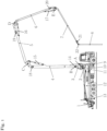
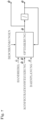
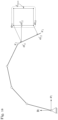
- FIG. 1 The relevant elements of an embodiment of a truck-mounted concrete pump according to the invention are shown. This has an undercarriage with a chassis with several tire-equipped axles, by means of which the truck-mounted concrete pump can be moved on the road.
- the undercarriage is provided with front and rear support cylinders 9 and 10, which are arranged on foldable and/or telescopic struts 10 and 12.
- a transfer case 11 is also shown.
- the undercarriage carries a pump group 1 at the rear and, via a mast block 2, an articulated arm along which a delivery line (not shown) is guided.
- the articulated arm also known as a boom or placing boom, consists of a slewing block 3 and four segments 4 to 7 (any number of segments is possible), which are connected via joints A to E.
- Joint A on the vehicle enables the rotation of the slewing block 3 around the vertical axis, while joints B to E enable the pivoting of segments 4 to 7 around horizontal tilting axes.
- the actuators of the concrete pump consist of hydraulic cylinders 14 to 17 at the respective joints B to E and a hydraulic motor for the swivel joint A of the slewing block.
- the hydraulic cylinders 14 to 17 enable the movement of the placing boom in the vertical plane.
- the hydraulic motor rotates the entire boom around the vertical axis.
- the mast tip 22 is the tip of the placing boom. This can be selected as the TCP for the geometry control.
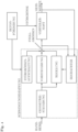
- the geometry control is used to generate the movement path for the placing boom, which is also referred to here as the trajectory.
- the movement path is a time function of the position, speed, acceleration and/or jerk of the joint axes of the placing boom. It is adapted to the dynamics of the system in the feedforward control and specified as a setpoint for the control system.
- the feedforward control is used to enable rapid movement of the placing boom without exciting its natural frequencies.
- the control system includes a control system for damping the natural vibrations of the articulated arm and a position control system. This is followed by an axis controller (not shown), which converts the target angular velocity of the joint into the actual actuator speed.
- the disturbance variable compensation is used to reduce vibrations in the placing boom induced by the concrete delivery.
- the present invention mainly relates to the structure and operation of the geometry control.
- the feedforward control, control, and disturbance compensation subsystems can be designed as described in the applications DE 10 2018 109 088 A1 , DE 10 2018 109 057 A1 and DE 10 2018 109 098 A1 is known. However, in possible alternative variants, other configurations of one or more of these subsystems can be used and/or one or more of these subsystems can be omitted.
- the geometry control can be Fig. 4 shown in the vibration damping system of the truck-mounted concrete pump.
- the trajectories of the geometry control are time functions for the position and speed of the articulated axes of the placing boom. They are adapted to the dynamics of the system in the feedforward control and specified as a setpoint for the control system.
- the resulting manipulated variables are used by the hydraulics of the concrete pump. converted into a movement. The control ensures that deviations from the target values are corrected.
- the inertial coordinate system (I) defines the task space of the manipulator.
- the pose x is described with respect to (I) and is generally composed of the position of a point and the orientation of the corresponding segment. Depending on the task description, however, the coordinate system (I) and thus the definition of x and the dimension m can change.
- the dimension n is equal to the number of independent joints and corresponds to the degrees of freedom of the system. For redundant manipulators, m ⁇ n applies.
- the Jacobian matrix from Eq. (3) is thus divided into a translational and a rotational part.
- J x J v x J ⁇ x .
- the Jacobian matrices J ⁇ x q and J ⁇ x q describe the influence of the actuated and elastic joint velocities ⁇ and ⁇ on the velocity ⁇ . They are each dependent on q , ie on the actuated and the elastic coordinates.
- the core of the geometry control is the solution of a quadratic optimization problem for inverting the kinematics under constraints.
- the optimization problem is solved anew at each time step.
- a general convex quadratic optimization problem is given by min x x T Wx + g T x under der Bd .
- Cx ⁇ b given, where x ⁇ R n the optimization variable, W ⁇ R n ⁇ n a positive definite weighting matrix, g ⁇ R n the linear part of the objective function, C ⁇ R p ⁇ n the matrix of linear inequality constraints and b ⁇ R p represents the constant offset of the constraints.
- Equation (12) is the objective function of the optimization. It consists of the individual objectives f 1 to f 3 .
- the function f 1 is the primary goal of the optimization.
- the speed ⁇ is chosen so that the target speed ⁇ ⁇ l with minimal error.
- the manipulator thus follows the desired target speed in the task space l.
- the definition of the task space l depends on the operating modes of the controller. They are presented below in Section 4.1.
- the positive definite matrix W ⁇ ⁇ ⁇ R m ⁇ m weights the entries of the primary target. This can influence the type of movement (see section 4.2).
- the function f 2 is the secondary goal of the optimization. It determines the configuration or pose of the manipulator by specifying the target speeds ⁇ ⁇ k influenced.
- the Matrix ⁇ ⁇ ⁇ k ⁇ J ⁇ k is a rotary Jacobian matrix defined according to Eq. (5).
- the positive definite matrix W ⁇ ⁇ ⁇ R n ⁇ n weights the differences of the objective function.
- the target speeds ⁇ ⁇ k are defined with respect to the coordinate system (k) . Depending on the task, relative or absolute velocities can be specified. Configuration control is discussed in Section 5.1.
- the function f 3 weights the joint velocities ⁇ and limits their magnitude. This is particularly necessary in the vicinity of singularities to avoid high velocities.
- the function f 3 thus represents a damping term of the optimization problem, the influence of which is determined via the weighting matrix W ⁇ ⁇ R n ⁇ n
- the approach is based on the damped least squares method. From a numerical perspective, this improves the stability of the problem.
- this is a multi-objective optimization. Normally, all objectives can be met through the manipulator's redundancy. If the number of objectives exceeds the redundant degrees of freedom, a Pareto-optimal compromise solution can still be found. This solution minimizes the error of all requirements in the least-squares sense.
- the available redundant degrees of freedom depend on the number of active constraints and change during operation.
- Constraint (16) represents component constraints of the optimization problem. These are direct constraints on the optimization variable ⁇ .
- the component constraints limit the position, velocity, and acceleration of the joints in the configuration space. They are explained in Section 6.
- Constraint (17) describes the constraints in the task space. For example, obstacles and walls are integrated into the problem.
- the Jacobian matrix J a ⁇ R p ⁇ n consists of the Jacobian matrices of individual points of the manipulator in different coordinate systems. The number of constraints p depends on the constraints in the task space (described in Section 7).
- the constraint (18) takes the hydraulic constraints into account. This results in a weighted L1-norm constraint that can be integrated into the optimization problem using various methods.
- the dimension of the matrix C h depends on the choice of method.
- the QP (12)-(18) is calculated at each discrete time (see Fig. 7 ) is solved again.
- a numerical solver calculates the optimal target velocity ⁇ k +1 while observing all constraints.
- a target position is calculated from the target velocity by integration.
- the variables ⁇ k +1 , ⁇ k +1 are the target values for the subsequent axis control, which converts the specified values into a movement on the real system.
- the basic structure of the algorithm is known as "Resolved Motion Rate Control.”
- the local approach keeps the computational requirements low compared to a global calculation.
- the algorithm can respond flexibly to changing environmental conditions or operating modes due to its iterative structure.
- ⁇ k + 1 ⁇ k + 1 + ⁇ ⁇ k ⁇ t .
- the task or the desired operating mode of the manipulator defines the task space and thus the target speed ⁇ ⁇ l and the Jacobian matrix J l in the primary single objective f 1 (12).
- the operating modes of the geometry control are joint angle control, cylinder coordinate control, 3D speed control, and fully automatic control.
- the meaning of the hand lever signals changes depending on the control mode.
- the control modes can be changed during operation.
- the joint angle control represents the original single-axis control, where the speeds of the joints are specified individually.
- constraints in the joint and task space such as maximum joint speeds or obstacles, can be taken into account.
- the target speed ⁇ cyl is composed of the coordinates of the TCP speed in the task space ⁇ ⁇ x cyl , ⁇ ⁇ y cyl and the joint velocity around the vertical axis ⁇ 0 .
- the Jacobian matrix J tcp only includes the kinematics of the planar manipulator, since ⁇ 0 is controlled directly. With the cylinder coordinate control, TCP movements can be performed with constant height or constant radial distance from the mast support.
- the fully automatic control no longer receives speed specifications from the operator, but rather position specifications from a higher-level path planning module.
- the advantage of this interconnection of path planning and geometry control is that only the basic movement needs to be specified.
- the geometry control handles the actual trajectory planning, taking into account the constraints of the system and the environment. This eliminates the time-consuming task of planning a permissible trajectory in the task space.
- the disadvantage of this approach is that local minima can occur in the solution. In this case, the manipulator cannot complete its movement and comes to a standstill despite all constraints being taken into account.
- the control modes are linked to a configuration control with which desired poses of the manipulator can be specified during the movement. This also applies to changing or locking the inclination of individual segments while maintaining the TCP movement.
- the TCP movement is determined by specifying a target velocity in the objective function (13).
- a target velocity in the objective function (13).
- Several operating modes of the manipulator are described in Section 4.1. In addition to the control mode, there are additional requirements for the TCP movement.
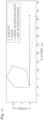
- the end effector should follow the target velocity as closely as possible, with the direction of the target velocity being more important than its magnitude.
- the manipulator cannot reach certain target speeds due to physical constraints. These constraints include, for example, the finite speed of the actuators or the obstacles in the environment. In this case, an error for the target value is introduced into the optimization problem. allowed to fulfill the constraints.
- the manipulator either keeps the velocity constant and deviates from the specified direction, or reduces the velocity and maintains the direction. From an usability perspective, the latter behavior is desirable because the manipulator moves in the specified direction at the maximum possible velocity. Due to the quadratic error term in the objective function, the optimization algorithm tends to maintain the velocity and yield in direction. This behavior can be changed by a suitable choice of the weighting matrix W ⁇ in Eq. (13).
- the error between the target and actual values in certain directions is reduced.
- the speed in the vertical direction can be given greater weight to prevent a deviation in that direction.
- this approach only works for movements in the vertical and horizontal directions. For oblique target speeds, there is no defined direction in the weighting matrix.
- the end effector coordinate system (e) is rotated by an angle ⁇ to the inertial coordinate system, so that the x e- axis points in the direction of the desired velocity (see Fig. 8 ). This is therefore determined by a single coordinate.
- ⁇ ⁇ e The objective function (13) expresses the actual velocity of the end effector with respect to (e).
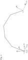
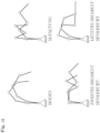
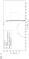
- Fig. 5 shows the rigid and the elastic manipulator under dead weight with the same angle values ⁇ .
- ⁇ i a significant deviation in the position of the mast tip is visible between the rigid and the elastic model.
- the elastic deflections accumulate up to the mast tip. To make matters worse, the deflection depends on the manipulator's posture. Therefore, compensation using a constant correction factor is not possible.
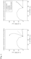
- Fig. 10 shows the same geometry control on a rigid and elastic manipulator. The position dependence of the static deflection is clearly visible.
- the model represents the arm elasticities of the segments through the elastic coordinates ⁇ .
- the proposed method applies not only to the discrete consideration of elasticities, but also to general flexible multibody modeling.
- appropriate discretization approaches such as the Ritz approach, the finite element method, and others, a finite-dimensional model of the distribution boom can be generated and converted into the form (26).
- the corrected Jacobian matrix J d replaces the original Jacobian matrix in the optimization problem (12)-(18).
- the advantage is that the static deformation is already taken into account in the optimization. This eliminates the need for subsequent correction and thus the potential violation of constraints. Furthermore, the problem retains the simple structure of Fig. 7 .
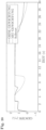
- the Fig. 11 shows the function of the geometry control with and without deformation compensation.
- the compensation prevents the mast tip from lowering due to elastic deflection and enables a straight-line movement.
- the concrete delivery acts as an additional force on the placing boom.
- the weight of the concrete in the delivery pipe increases the deformation in the segments and must therefore be taken into account in the deformation compensation.
- the inertial forces are calculated using the volume of the delivery pipe and the density of the concrete and incorporated into the model using Equation (30).
- the concrete density is determined either during runtime using the measured variables of the concrete delivery or a stored average density is used.
- the fill level of the delivery pipe can vary depending on the operating state of the pump and the boom position. The reason for this is that when the pump is idle or the pumping frequency is low, some of the concrete flows out due to gravity, thus reducing the fill level in the front area of the placing boom. This effect can also be taken into account depending on the boom position and the operating state of the pump.
- the iterative structure of the geometry control allows even strongly varying mass ratios over time to be compensated without difficulty.
- the exemplary embodiment of the present invention uses a damped least squares method to improve robustness against singularities.
- configuration control is incorporated as an additional task into the objective function of the optimization problem.
- the configuration is controlled by minimizing the squared error and is thus independent of the number of degrees of freedom.
- the priority of configuration control over the TCP target movement is determined via weightings in the objective function.
- the target movement is defined as the primary task and configuration control as the secondary task.
- the configuration control is independent of the number of Degrees of freedom of the manipulator. If the redundant degrees of freedom are smaller than the number of tasks due to active constraints, an optimal solution is calculated in terms of the least square error. This means that the priority of the TCP setpoint and configuration control must be determined by the weightings. A higher weighting of the TCP setpoint means preference in critical situations. The configuration is then abandoned in favor of the TCP movement, for example, to maximize the range or avoid an obstacle. Constant angles are suggested for the selection of the setpoint angles k ⁇ to determine the pose.
- the target position is an extreme position that only serves to fundamentally define the posture. The weighting is chosen so low that the posture is not completely controlled.
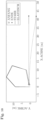
- Table 1 shows the target angles k ⁇ for the configurations in Fig. 12
- the target angles are defined so that the first three segments point vertically upwards and the last three vertically downwards. Due to a low weighting, this results in the primary goal of the sheet folding in Fig. 12 .
- the target angle of the first segment can be kept close to vertical, while the other joints execute the target movement of the TCP.
- Fig. 12 it is also possible for the operator to change the position of individual segments or to define their own configuration at any time.
- One scenario for example, is to hold a segment at a defined angle.
- the configuration control maintains this configuration for as long as possible and only releases it in critical situations, such as when an obstacle is encountered. If the configuration of one or more segments must be adhered to under all circumstances, a restriction in the configuration space (see section 6) is more suitable. This ensures that the specification is adhered to unconditionally. However, the configuration cannot then be given in critical situations.
- Specifying constant target angles has the disadvantage that the exact attitude only becomes apparent through optimization. This means that the configuration is not precisely defined from the outset.
- An alternative is to specify the target angles based on the position. To do this, a clear relationship is established between the TCP position and the target configuration, and a new target angle k ⁇ is calculated in each time step.
- configuration control can be used to optimize other secondary objectives. Examples include optimizing drive torques, drive torques with contact forces, end effector sensitivity, dexterity, kinetic energy, and reliability.
- the configuration control from the previous section allows for configuration control while specifying a target speed for the TCP. This requires continuous specification of the TCP speed by the operator. For fully automated movement, the operator is eliminated. Instead, a higher-level path planning module coordinates the movement sequence. A stored path is specified, which divides the movement into point-to-point movements.
- Equation (33) point-to-point movements can be easily implemented in the configuration space. This approach can be applied analogously to the task space.
- the path planning module coordinates the movement process and switches to the next setpoint upon reaching a defined environment. This results in smooth movement of the manipulator and avoids standstills at intermediate points.
- the typical application of autonomous operation is automatic folding and unfolding.
- the manipulator is automatically moved from the folded transport position to a working configuration or from any working configuration to the transport position.
- the manipulator's spatial requirements can also be controlled. This is an advantage over pure trajectory planning at the configuration or task space level. Furthermore, constraints such as actuator acceleration, hydraulic flow, or obstacles in the task space are already taken into account by the geometry control.
- the unfolding and folding process is carried out by specifying target configurations in combination with a slightly weighted TCP speed. To avoid collisions between the segments and the vehicle, a sequence of individual joint movements is necessary at the beginning of the unfolding process. As soon as the appropriate space is available, a combined movement into the target configuration is carried out. The slight weighting of the TCP speed prevents sweeping movements of the TCP in the workspace. The unfolding process does not have to be waited for completely. Instead, control can begin as soon as the TCP is free. The configuration control from Section 5.1 then takes over the control of the desired attitude during operation.
- the algorithm ensures that, in the case of a wall constraint (see Section 7.1), no segment point exceeds the maximum limit and the manipulator still reaches the final position. It is important that the desired movement is compatible with the selected constraints. This means that the unfolding process must be physically possible. Otherwise, the manipulator will only move up to the constraint limit.
- the folding process is analogous to the unfolding process in reverse.
- the folding process can be started from any initial position.
- a slightly weighted TCP velocity toward the final pose is also specified. This facilitates the folding process and reduces the required working space for the TCP. If the TCP is already in the desired position, it can easily perform evasive movements in the opposite direction due to the low weighting.
- Simultaneously specifying target configurations and TCP speeds improves the manageability of automatic unfolding and folding. This allows for easy specification of target positions at the configuration level while controlling the TCP position in the task space.
- the component constraints (16) of the optimization problem allow for constraints on the joint velocities ⁇ . To account for position or acceleration constraints, these must be converted to velocity. Joints with hydraulic cylinders also feature a coupling mechanism to convert the cylinder's translational motion into a rotational motion.
- the maximum permissible speed is calculated, which allows the vehicle to come to a stop at the position restriction with a maximum permissible, constant braking acceleration.
- the value 2 a _ d ⁇ ⁇ d the permissible speed. This speed is chosen so that when braking with acceleration ⁇ , a standstill after the distance d - d is reached. If the maximum position is exceeded, the maximum speed is set to zero. This means that movement in the positive direction is no longer possible.
- the quantities ⁇ , ⁇ are the minimum and maximum permissible cylinder speeds.
- the acceleration limits are determined by the difference quotient a _ ⁇ ⁇ ⁇ ⁇ old ⁇ t ⁇ a ⁇ , where ⁇ , ⁇ is the maximum or minimum acceleration, ⁇ old is the speed from the previous time step and ⁇ t is the step size.
- the constraint (69) is not continuously differentiable and therefore cannot be directly considered in the optimization problem.
- the L1-norm constraint (69) can be transformed into a set of linear constraints using relatively simple methods. Two possible approaches are presented below.
- the first method is based on the naive resolution of the absolute values in Eq. (69). This results in a linear constraint for every possible combination of signs of the optimization variables.
- the transformation of the L1-norm constraints with three optimization variables leads to the linear constraints + a 1 x 1 + a 2 x 2 + a 3 x 3 ⁇ b , ⁇ a 1 x 1 + a 2 x 2 + a 3 x 3 ⁇ b , + a 1 x 1 ⁇ a 2 x 2 + a 3 x 3 ⁇ b , + a 1 x 1 + a 2 x 2 ⁇ a 3 x 3 ⁇ b , ⁇ a 1 x 1 ⁇ a 2 x 2 + a 3 x 3 ⁇ b , ⁇ a 1 x 1 + a 2 x 2 ⁇ a 3 x 3 ⁇ b , + a 1 x 1 ⁇ a 2 x 2 ⁇ a 3
- the hydraulic power can also be limited.
- the flow rate of the individual actuators can also be restricted.
- Q ⁇ h , i ⁇ k h i ⁇ ⁇ i ⁇ Q ⁇ h , i , i 0 , ... , 5 , where Q h,i' Q h, i define the minimum and maximum permissible flow rate for actuator i.
- the hydraulics of the concrete pump use a load-sensing system.
- the flow rate of an actuator is proportional to its speed.
- the individual flow limitation per actuator is thus another form of speed limitation (110).
- constraints (17) allow the integration of constraints in the task space. This allows the velocity of any point on the manipulator to be kept within defined values with respect to a vehicle-fixed coordinate system. For example, a virtual wall represents a boundary in the task space that the manipulator must not exceed.
- position and acceleration constraints must be converted into corresponding requirements at the velocity level.
- the thus calculated permissible velocities are defined in the task space.
- the optimization variables are transformed into the task space using the Jacobian matrix and compared with the permissible velocities in a defined direction.
- the goal of collision avoidance is to prevent any point on the manipulator from colliding with an obstacle.
- the velocity of the critical point should be limited so that the manipulator or segment always comes to a stop before the obstacle with a defined braking acceleration. Velocities not pointing in the direction of the obstacle are not restricted.
- the approach is defined by general inequality constraints in the problem space. These are taken into account in the optimization problem through constraints.
- the inequality constraints have several advantages. For example, the constraint is only active when a collision course exists.
- the optimization algorithm ensures efficient management of active and inactive constraints.
- the redundant degrees of freedom of the manipulator are used to avoid collision with the obstacle without influencing the operator's speed specification. If the number of constraints exceeds the redundant degrees of freedom, an optimal solution is calculated in the sense of the least squared error while observing the constraints.
- the constraints are strictly adhered to. In critical situations, this means abandoning the operator's specifications in order to comply with the constraints. The manipulator may then come to a complete standstill in order to avoid colliding with the obstacle. This is an advantage over methods with collision avoidance in the objective function.
- the inequality constraint also enables travel along the edge of an obstacle. Since only the approach speed towards the obstacle is limited, movement along the edge is possible without restrictions using an orthogonal speed.
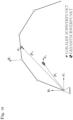
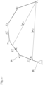
- the critical points on the manipulator and obstacle are obtained by double projection (see Fig. 14 ).
- the double projection calculates the critical manipulator points o' jk that are the shortest distances to the corner points of the obstacle j (for the calculation of the shortest distance from point to segment, see Appendix 9.5). From the set of points, the critical points o' jk with the shortest distance d ( o jk , o' jk ) are selected.
- the critical obstacle points o" jk are calculated using these points. They are the points on the edges of the obstacle that are the shortest distances to the critical manipulator points o' jk .
- the critical points o" jk with the shortest distance d ck ( o' jk , o" jk ) are again selected. This results in pairs of critical points on the segment and obstacle edge with the corresponding distances d ck .
- the first step results in the critical points o ' j 1 and o' j 2 .
- the original obstacle corner o j 2 is again obtained.
- the starting speed represents the speed of the critical manipulator points in the direction of the obstacles. It is thus determined by ⁇ a ik ⁇ ⁇ ⁇ ik d c k limited, with the maximum permissible speed ⁇ ik depends on the distance d ck . Inserting Eq. (77) into (79) yields a linear, scalar inequality restriction in the problem space J a ik ⁇ ⁇ ⁇ ⁇ ik d c k .
- the double projection has the advantage that speed restrictions on an obstacle corner are transformed into a restriction on the obstacle edge.
- Fig. 14 the direction o j 1 - o' j 2 towards the obstacle corner is converted into the direction o' j 1 - o" j 2. This allows unrestricted travel of the segment parallel to the obstacle edge. This is particularly relevant if the segment continues its parallel travel past the corner o j 1. The obstacle area is left without any speed restriction. If the direction towards an obstacle corner cannot be transformed due to the geometry, the double projection results in the original direction. This is in Fig. 14 for o j 2 can be seen.
- the maximum permitted speed ⁇ ik ( d ck ) is calculated analogously to Section 6. Instead of at the cylinder level, the velocities in the task space are defined as a function of the distance d ck . This allows for the implementation of position, velocity, and acceleration constraints in the task space.
- the safety distance d max is determined by the segment shape. Furthermore, uncertainties in the position and the space requirements of transient residual vibrations of the manipulator can be taken into account.
- the maximum permissible braking acceleration ⁇ must be set to be less than or equal to the physically possible deceleration acceleration. Due to the nonlinear kinematics, a transformation of the accelerations from the configuration space to the task space is not possible, as this does not guarantee a consistent deceleration process.
- velocity and acceleration constraints can be implemented for any manipulator point, analogous to Section 6.
- the Jacobian matrix must be adapted to the respective point.
- the velocity constraint can be used, for example, to comply with the legally prescribed maximum TCP velocity.
- Wall constraints are a special form of the position constraints described in the previous section. Their special form results in significant simplifications in the collision avoidance algorithm from Section 7.
- the virtual center of gravity of the manipulator is restricted in the x-direction of the vehicle-fixed coordinate system in order to maintain the stability of the vehicle (see Fig. 16 ).
- the position constraint of the center of gravity is a special form of the wall constraint from section 7.1. Since the constraint is only active in the direction of the x 0 -axis of the inertial coordinate system, the distance determination.
- the positions are defined with respect to a common coordinate system.
- the velocity of the total center of mass ⁇ s in the task space is calculated from the velocity of the individual center of mass ⁇ s i of the segments.
- the position and velocity of the center of mass of the complete manipulator are the weighted sum of the individual centers of mass of the bodies.
- Equation (90) the velocity of the total center of gravity is calculated from the Jacobian matrices of the joints i.
- Self-collision is the collision between segments.
- the risk of self-collision increases with the number of redundant degrees of freedom.
- the manipulator's joint kinematics determine the poses at which self-collision is at risk.
- the configuration space constraints in Section 6 prevent collisions between neighboring segments through positional constraints. However, this does not affect the collision of more distant segments.
- the relative position or speed must be limited.
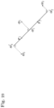
- the Fig. 17 shows the position vector 1 p 16 of the joint point r 6 to a point on segment 1 in the local coordinate system of segment 1.
- Equation (96) limits the starting speeds orthogonal to the segment.
- the permissible speed ⁇ ( d ck ) is obtained analogously to Eq. (81).
- the position d i is derived using a suitable filter.
- the relationship to the joint velocity ⁇ i is thus obtained from the time derivative of Eq. (101).
- the concrete pump has five rotary joints for moving the placing boom in the vertical plane.
- a hydraulic cylinder is located at each joint to actuate the boom. The translational movement of the cylinders is converted into rotation of the joints via a coupling gear.
Landscapes
- Engineering & Computer Science (AREA)
- Architecture (AREA)
- Mechanical Engineering (AREA)
- Civil Engineering (AREA)
- Structural Engineering (AREA)
- Robotics (AREA)
- On-Site Construction Work That Accompanies The Preparation And Application Of Concrete (AREA)
- Reciprocating Pumps (AREA)
- Control Of Non-Positive-Displacement Pumps (AREA)
- Structures Of Non-Positive Displacement Pumps (AREA)
Claims (14)
- Pompe à béton, en particulier pompe à béton automatique, comprenant un bras articulé le long duquel est guidé une conduite de transport pour le béton et comprenant une commande de bras articulé pour le bras articulé de la pompe à béton, le bras articulé présentant un support rotatif (3) pouvant tourner autour d'un axe vertical et au moins deux segments (4-7) pouvant pivoter autour d'axes horizontaux au moyen d'articulations (B-E), le support rotatif (3) pouvant être déplacé autour de l'axe vertical (A) par l'intermédiaire d'un actionneur et les segments (4-7) pouvant pivoter autour des axes horizontaux par l'intermédiaire d'actionneurs (14-17), des capteurs (18-21) étant de préférence prévus pour déterminer l'angle de rotation du support rotatif (3) et pour déterminer l'angle d'articulation des articulations (B-E),la commande de bras articulé servant à commander les actionneurs (14-17) et comprenant une commande géométrique, qui, à partir de valeurs d'entrée pour un mouvement TCP de consigne, génère une trajectoire avec des valeurs de consigne pour le mouvement du support rotatif (3) et/ou des articulations (B-E), la commande géométrique déterminant la trajectoire en résolvant un problème d'optimisation, le problème d'optimisation minimisant, en tant que fonction cible, un écart entre le mouvement TCP de consigne et un mouvement TCP résultant de la trajectoire dans un modèle physique du bras articulé,caractérisée en ce queles restrictions de l'hydraulique et/ou de l'espace de travail sont incluses dans l'optimisation en tant que condition secondaire.
- Pompe à béton selon la revendication 1, le débit volumique maximal disponible et/ou la puissance maximale disponible de l'alimentation hydraulique étant inclus dans l'optimisation en tant que condition secondaire.
- Pompe à béton selon la revendication 1 ou 2, la commande géométrique comprenant une fonction d'évitement des collisions du bras articulé avec des contours gênants, les restrictions de l'espace de travail formées par les contours gênants étant incluses dans l'optimisation en tant que condition secondaire.
- Pompe á béton selon la revendication 3, la fonction d'évitement des collisions du bras articulé avec des contours gênants limitant la vitesse d'approche du bras articulé vers un contour gênant à une valeur qui permet un freinage avant d'atteindre le contour gênant.
- Pompe à béton selon la revendication 3 ou 4, les contours gênants pouvant être entrés dans la commande de bras articulé en tant que murs et/ou plafonds virtuels, et/ou une reproduction virtuelle des obstacles étant effectuée par l'intermédiaire d'une interface utilisateur de préférence graphique, par exemple en entrant une hauteur de plafond et une distance par rapport au bâtiment, et/ou les contours gênants peuvent être entrés par un procédé d'apprentissage, en particulier par le fait qu'un utilisateur définit une position maximale en approchant de la position, et/ou une interface étant prévue pour une modélisation des données de l'ouvrage, par l'intermédiaire de laquelle la position de contours gênants peut être introduite dans la commande à partir d'un modèle virtuel du bâtiment et/ou du chantier, une localisation de la pompe à béton s'effectuant de préférence par l'intermédiaire d'une détection de position par satellite, et/ou une détection des contours gênants s'effectuant par l'intermédiaire d'un système de détection de distance sur le mât de distribution, en particulier d'un système de détection de distance optique, mécanique, électromagnétique et/ou acoustique.
- Pompe à béton selon l'une quelconque des revendications 3 à 5, la fonction d'évitement des collisions permettant un déplacement parallèlement à un contour gênant à pleine vitesse.
- Pompe à béton selon l'une quelconque des revendications précédentes, la commande géométrique comprenant une fonction de stabilité qui détermine la position du centre de gravité de la pompe à béton, l'exigence que le centre de gravité de la pompe à béton se trouve dans une zone sûre étant incluse dans l'optimisation en tant que condition secondaire.
- Pompe à béton selon l'une quelconque des revendications précédentes, les restrictions de collision propres pour éviter des collisions des segments (4-7) entre eux et/ou avec d'autres éléments de la pompe à béton étant incluses dans l'optimisation en tant que condition secondaire.
- Pompe à béton selon l'une quelconque des revendications précédentes, comprenant un module de planification de trajectoire pour la réalisation automatique d'un mouvement du bras articulé et/ou du TCP, une valeur de consigne générée par le module de planification de trajectoire étant incluse comme entrée dans la commande géométrique.
- Pompe à béton selon la revendication 9, le module de planification de trajectoire décrivant de manière simplifiée ou ne tenant pas compte de restrictions de l'espace de travail par rapport au problème d'optimisation et/ou une valeur de consigne générée par le module de planification de trajectoire étant incluse comme entrée dans la commande géométrique de la même manière qu'un signal de levier manuel.
- Pompe à béton selon l'une quelconque des revendications précédentes, le modèle physique du bras articulé utilisé dans le problème d'optimisation tenant compte d'une déformation du bras articulé due à son propre poids et/ou au poids du béton transporté.
- Pompe à béton selon l'une quelconque des revendications précédentes, le problème d'optimisation minimisant l'écart entre le mouvement TCP de consigne et le mouvement TCP résultant de la trajectoire dans un modèle physique du bras articulé en tant que première fonction cible et un écart d'une configuration du bras articulé par rapport à une configuration de consigne en tant que deuxième fonction cible.
- Pompe à béton selon l'une quelconque des revendications précédentes, la commande géométrique comprenant un solveur numérique qui résout de nouveau le problème d'optimisation à chaque pas de temps et/ou le problème d'optimisation étant formulé comme un problème d'optimisation quadratique, les vitesses perpendiculaires à une direction de la vitesse TCP de consigne étant de préférence plus fortement pondérées dans le problème d'optimisation que les vitesses dans la direction de la vitesse TCP de consigne.
- Procédé de commande d'une pompe à béton selon l'une quelconque des revendications précédentes, une commande de bras articulé étant utilisée.
Applications Claiming Priority (1)
| Application Number | Priority Date | Filing Date | Title |
|---|---|---|---|
| DE102019105817.1A DE102019105817A1 (de) | 2019-03-07 | 2019-03-07 | Gelenkarm-Steuerung einer Betonpumpe |
Publications (3)
| Publication Number | Publication Date |
|---|---|
| EP3705663A1 EP3705663A1 (fr) | 2020-09-09 |
| EP3705663B1 EP3705663B1 (fr) | 2022-08-24 |
| EP3705663B2 true EP3705663B2 (fr) | 2025-04-16 |
Family
ID=69770627
Family Applications (1)
| Application Number | Title | Priority Date | Filing Date |
|---|---|---|---|
| EP20160939.3A Active EP3705663B2 (fr) | 2019-03-07 | 2020-03-04 | Commande à bras articulaire d'une pompe à béton |
Country Status (3)
| Country | Link |
|---|---|
| EP (1) | EP3705663B2 (fr) |
| DE (1) | DE102019105817A1 (fr) |
| ES (1) | ES2930445T3 (fr) |
Families Citing this family (13)
| Publication number | Priority date | Publication date | Assignee | Title |
|---|---|---|---|---|
| DE102021107141A1 (de) | 2021-03-23 | 2022-09-29 | Putzmeister Engineering Gmbh | Standsicherheitsüberwachung für ein Dickstofffördersystem |
| DE102021107140A1 (de) | 2021-03-23 | 2022-09-29 | Putzmeister Engineering Gmbh | Ausfallsichere Standsicherheitsüberwachung für ein Dickstofffördersystem |
| CN113021408B (zh) | 2021-03-23 | 2022-08-05 | 中联重科股份有限公司 | 补偿臂架挠度的方法和装置及控制臂架的方法和装置 |
| DE102021207097A1 (de) | 2021-07-06 | 2023-01-12 | Putzmeister Engineering Gmbh | Verfahren und System zum Steuern einer Bewegung eines verstellbaren Verteilermasts und Verfahren zum Verteilen von Bau- und/oder Dickstoff mittels einer Bau- und/oder Dickstoffpumpenvorrichtung aufweisend einen verstellbaren Verteilermast |
| DE102021207092A1 (de) | 2021-07-06 | 2023-01-12 | Putzmeister Engineering Gmbh | Verfahren zum automatischen Einstellen einer veränderbaren Maststellung eines verstellbaren Verteilermasts einer Bau- und/oder Dickstoffpumpenvorrichtung und System |
| CN114562111B (zh) * | 2022-02-14 | 2023-09-08 | 三一汽车制造有限公司 | 臂架位置确定方法、装置、设备及作业机械 |
| CN115847403B (zh) * | 2022-11-28 | 2026-03-17 | 中联重科股份有限公司 | 工程机械臂架路径规划方法及装置 |
| DE102023121709A1 (de) * | 2023-08-14 | 2025-02-20 | Liebherr-Mischtechnik Gmbh | Vorrichtung mit Gelenkarm und Verfahren zum Steuern eines solchen |
| DE102023124619A1 (de) * | 2023-09-12 | 2025-03-13 | Schwing Gmbh | Großmanipulator und Verfahren zur Steuerung eines Großmanipulators |
| DE102024102463A1 (de) | 2024-01-29 | 2025-07-31 | Putzmeister Engineering Gmbh | Betonpumpe und Verfahren zum Betreiben einer Betonpumpe |
| EP4663355A1 (fr) * | 2024-06-12 | 2025-12-17 | Hilti Aktiengesellschaft | Robot de construction et procédé de commande d'un robot de construction |
| AT528683A1 (de) * | 2024-10-14 | 2026-04-15 | Schwing Gmbh F | Großmanipulator und Verfahren zum fortlaufenden Ableiten eines dreidimensionalen Umgebungsmodells der Umgebung eines Großmanipulators |
| CN119847009B (zh) * | 2024-11-12 | 2025-10-10 | 中国建筑第八工程局有限公司 | 一种混凝土自动浇注控制方法、系统及相关设备 |
Citations (8)
| Publication number | Priority date | Publication date | Assignee | Title |
|---|---|---|---|---|
| DE10060077A1 (de) † | 2000-12-01 | 2002-06-06 | Putzmeister Ag | Vorrichtung zur Betätigung des Knickmasts eines Großmanipulators |
| DE10101570A1 (de) † | 2001-01-15 | 2002-08-14 | Schwing Gmbh F | Großmanipulator mit Schwingungsdämpfung |
| EP1537282B1 (fr) † | 2002-08-27 | 2006-12-20 | PUTZMEISTER Aktiengesellschaft | Manipulateur de grande taille avec un mât articulé et avec un dispositif de réglage pour commander ledit mât |
| DE102009054160A1 (de) † | 2009-11-23 | 2011-05-26 | Wocken Industriepartner Gmbh & Co. Kg | Reinigungsanlage für eine Solaranlage |
| WO2015197708A1 (fr) † | 2014-06-25 | 2015-12-30 | Schwing Gmbh | Manipulateur de grande taille, mobile |
| DE102016106406A1 (de) † | 2016-04-07 | 2017-10-12 | Schwing Gmbh | Kartesische Steuerung einer Mastspitze eines Großmanipulators |
| DE102016122392A1 (de) † | 2016-11-21 | 2018-05-24 | Schwing Gmbh | Dickstoffpumpe mit einstellbarer Begrenzung des Förderdrucks |
| WO2018115248A1 (fr) † | 2016-12-21 | 2018-06-28 | Schwing Gmbh | Manipulateur de grande taille avec structure de mât automatisée |
Family Cites Families (17)
| Publication number | Priority date | Publication date | Assignee | Title |
|---|---|---|---|---|
| DE4306127C2 (de) * | 1993-02-27 | 2002-08-08 | Putzmeister Ag | Großmanipulator, insbesondere für Autobetonpumpen |
| DE4412643A1 (de) * | 1993-08-26 | 1995-03-02 | Putzmeister Maschf | Großmanipulator, insbesondere für Autobetonpumpen, sowie Verfahren zu dessen Handhabung |
| DE19503895A1 (de) * | 1995-02-07 | 1996-08-08 | Putzmeister Maschf | Betonpumpe mit Verteilermast |
| DE102006049487A1 (de) * | 2005-10-18 | 2007-04-26 | Putzmeister Ag | Arbeitsmast, insbesondere für Großmanipulatoren und fahrbare Betonpumpen |
| DE102006007623B4 (de) * | 2006-02-18 | 2015-06-25 | Kuka Laboratories Gmbh | Roboter mit einer Steuereinheit zum Steuern einer Bewegung zwischen einer Anfangspose und einer Endpose |
| ITMI20060818A1 (it) * | 2006-04-24 | 2007-10-25 | Cifa Spa | Sistema perfezionato per la sorveglianza e il controllo del funzionamento di macchinari semoventi a braccio articolato,quali pompe per calcestruzzo |
| DE102008055625A1 (de) * | 2008-11-03 | 2010-05-06 | Putzmeister Concrete Pumps Gmbh | Fahrbare Arbeitsmaschine mit Stützauslegern |
| CN102346025B (zh) * | 2011-07-12 | 2013-04-24 | 三一重工股份有限公司 | 获得臂架系统末端位置参数的方法、臂架系统及工程机械 |
| CN102385391B (zh) * | 2011-07-14 | 2014-09-10 | 中联重科股份有限公司 | 机械臂的控制方法与控制装置以及工程机械 |
| CN102561700B (zh) * | 2012-01-16 | 2014-05-21 | 三一重工股份有限公司 | 一种机械臂控制系统、方法及工程机械 |
| CN102588505B (zh) * | 2012-02-06 | 2014-01-15 | 三一汽车制造有限公司 | 泵车稳定性控制系统、控制方法及泵车 |
| CN103955231B (zh) * | 2013-12-31 | 2015-05-13 | 三一汽车制造有限公司 | 多关节机械臂智能控制方法、装置及系统 |
| CN103806666B (zh) * | 2014-01-26 | 2015-02-18 | 三一汽车制造有限公司 | 一种混凝土泵车和臂架控制方法 |
| CN103806667B (zh) * | 2014-01-26 | 2015-12-30 | 三一汽车制造有限公司 | 一种混凝土泵车及臂架控制方法与控制装置 |
| DE102018109088A1 (de) | 2018-04-17 | 2019-10-17 | Liebherr-Mischtechnik Gmbh | Großmanipulator, insbesondere für Betonpumpen |
| DE102018109098A1 (de) | 2018-04-17 | 2019-10-17 | Liebherr-Mischtechnik Gmbh | Betonpumpe |
| DE102018109057A1 (de) | 2018-04-17 | 2019-10-17 | Liebherr-Mischtechnik Gmbh | Betonpumpe |
-
2019
- 2019-03-07 DE DE102019105817.1A patent/DE102019105817A1/de active Pending
-
2020
- 2020-03-04 ES ES20160939T patent/ES2930445T3/es active Active
- 2020-03-04 EP EP20160939.3A patent/EP3705663B2/fr active Active
Patent Citations (8)
| Publication number | Priority date | Publication date | Assignee | Title |
|---|---|---|---|---|
| DE10060077A1 (de) † | 2000-12-01 | 2002-06-06 | Putzmeister Ag | Vorrichtung zur Betätigung des Knickmasts eines Großmanipulators |
| DE10101570A1 (de) † | 2001-01-15 | 2002-08-14 | Schwing Gmbh F | Großmanipulator mit Schwingungsdämpfung |
| EP1537282B1 (fr) † | 2002-08-27 | 2006-12-20 | PUTZMEISTER Aktiengesellschaft | Manipulateur de grande taille avec un mât articulé et avec un dispositif de réglage pour commander ledit mât |
| DE102009054160A1 (de) † | 2009-11-23 | 2011-05-26 | Wocken Industriepartner Gmbh & Co. Kg | Reinigungsanlage für eine Solaranlage |
| WO2015197708A1 (fr) † | 2014-06-25 | 2015-12-30 | Schwing Gmbh | Manipulateur de grande taille, mobile |
| DE102016106406A1 (de) † | 2016-04-07 | 2017-10-12 | Schwing Gmbh | Kartesische Steuerung einer Mastspitze eines Großmanipulators |
| DE102016122392A1 (de) † | 2016-11-21 | 2018-05-24 | Schwing Gmbh | Dickstoffpumpe mit einstellbarer Begrenzung des Förderdrucks |
| WO2018115248A1 (fr) † | 2016-12-21 | 2018-06-28 | Schwing Gmbh | Manipulateur de grande taille avec structure de mât automatisée |
Non-Patent Citations (12)
Also Published As
| Publication number | Publication date |
|---|---|
| EP3705663A1 (fr) | 2020-09-09 |
| ES2930445T3 (es) | 2022-12-13 |
| EP3705663B1 (fr) | 2022-08-24 |
| DE102019105817A1 (de) | 2020-09-10 |
Similar Documents
| Publication | Publication Date | Title |
|---|---|---|
| EP3705663B2 (fr) | Commande à bras articulaire d'une pompe à béton | |
| EP3705664B1 (fr) | Commande à bras articulaire d'une pompe à béton | |
| EP3705662B1 (fr) | Commande à bras articulaire d'une pompe à béton | |
| EP3556969B1 (fr) | Pompe à béton | |
| EP3559374B1 (fr) | Manipulateur de grande taille avec structure de mât automatisée | |
| DE112021001104T5 (de) | Bewegungsplanungsverfahren mit kollisionsvermeidung für industrieroboter | |
| DE102021107453A1 (de) | Schnelle roboterbewegungsoptimierung mit distanzfeld | |
| DE3853616T2 (de) | Verfahren und Gerät zur Wegplanung. | |
| DE112019006532B4 (de) | Steuersystem für baumaschinen, baumaschine und steuerverfahren für baumaschinen | |
| EP2954986B1 (fr) | Dispositif et procédé de commande et de réglage d'un système multi-corps | |
| DE102021100324A1 (de) | Steuern der Bewegung einer Maschine unter Verwendung von Sensorfusion | |
| EP3556967B1 (fr) | Manipulateur de grande taille, en particulier pour pompes à béton | |
| DE112017002603B4 (de) | Steuerungssystem für eine baumaschine, baumaschine und steuerverfahren für eine baumaschine | |
| DE10240180A1 (de) | Vorrichtung zur Betätigung eines Knickmasts | |
| DE112019006225B4 (de) | Steuersystem für baumaschinen, baumaschine und steuerverfahren für baumaschinen | |
| DE102004026814A1 (de) | Verfahren und Vorrichtung zum Verbessern der Positioniergenauigkeit eines Handhabungsgeräts | |
| DE19810341C2 (de) | Verfahren zur automatischen Kollisionsvermeidung eines Manipulators in einem durch Hindernisse beschränkten Arbeitsraum | |
| WO2022236346A1 (fr) | Procédé de commande en boucle ouverte et/ou en boucle fermée d'un engin de levage monté sur un véhicule | |
| EP3556968A1 (fr) | Pompe à béton | |
| DE102023117136A1 (de) | Prädiktives regelungsverfahren zum regeln der drehmomentänderungsrate und zur schwingungsunterdrückung | |
| DE102021125628B3 (de) | Geschwindigkeitsvorgaben zur Trajektorienbestimmung von Kinematiken | |
| DE102022107587A1 (de) | Verfahren zur Gangsteuerung eines Roboters, Regler, Computerprogramm und Robotersystem | |
| DE102023126559B3 (de) | Verfahren und System zum Planen und Steuern des Gleichgewichts- und der Fortbewegung eines humanoiden zweibeinigen Roboters | |
| DE102005025536A1 (de) | Mobile Arbeitsmaschinen, insbesondere hydraulisch angetriebene Erdbaumaschinen, und Verfahren zur Erd- und Schüttgutbewegung | |
| DE102021111237B3 (de) | Beschleunigung direkter und indirekter Kinematiken |
Legal Events
| Date | Code | Title | Description |
|---|---|---|---|
| PUAI | Public reference made under article 153(3) epc to a published international application that has entered the european phase |
Free format text: ORIGINAL CODE: 0009012 |
|
| STAA | Information on the status of an ep patent application or granted ep patent |
Free format text: STATUS: THE APPLICATION HAS BEEN PUBLISHED |
|
| AK | Designated contracting states |
Kind code of ref document: A1 Designated state(s): AL AT BE BG CH CY CZ DE DK EE ES FI FR GB GR HR HU IE IS IT LI LT LU LV MC MK MT NL NO PL PT RO RS SE SI SK SM TR |
|
| AX | Request for extension of the european patent |
Extension state: BA ME |
|
| STAA | Information on the status of an ep patent application or granted ep patent |
Free format text: STATUS: REQUEST FOR EXAMINATION WAS MADE |
|
| 17P | Request for examination filed |
Effective date: 20210309 |
|
| STAA | Information on the status of an ep patent application or granted ep patent |
Free format text: STATUS: EXAMINATION IS IN PROGRESS |
|
| 17Q | First examination report despatched |
Effective date: 20210715 |
|
| GRAP | Despatch of communication of intention to grant a patent |
Free format text: ORIGINAL CODE: EPIDOSNIGR1 |
|
| STAA | Information on the status of an ep patent application or granted ep patent |
Free format text: STATUS: GRANT OF PATENT IS INTENDED |
|
| INTG | Intention to grant announced |
Effective date: 20220513 |
|
| GRAS | Grant fee paid |
Free format text: ORIGINAL CODE: EPIDOSNIGR3 |
|
| GRAA | (expected) grant |
Free format text: ORIGINAL CODE: 0009210 |
|
| STAA | Information on the status of an ep patent application or granted ep patent |
Free format text: STATUS: THE PATENT HAS BEEN GRANTED |
|
| AK | Designated contracting states |
Kind code of ref document: B1 Designated state(s): AL AT BE BG CH CY CZ DE DK EE ES FI FR GB GR HR HU IE IS IT LI LT LU LV MC MK MT NL NO PL PT RO RS SE SI SK SM TR |
|
| REG | Reference to a national code |
Ref country code: CH Ref legal event code: EP |
|
| REG | Reference to a national code |
Ref country code: IE Ref legal event code: FG4D Free format text: LANGUAGE OF EP DOCUMENT: GERMAN |
|
| REG | Reference to a national code |
Ref country code: AT Ref legal event code: REF Ref document number: 1513749 Country of ref document: AT Kind code of ref document: T Effective date: 20220915 Ref country code: DE Ref legal event code: R096 Ref document number: 502020001560 Country of ref document: DE |
|
| REG | Reference to a national code |
Ref country code: LT Ref legal event code: MG9D |
|
| REG | Reference to a national code |
Ref country code: ES Ref legal event code: FG2A Ref document number: 2930445 Country of ref document: ES Kind code of ref document: T3 Effective date: 20221213 |
|
| REG | Reference to a national code |
Ref country code: NL Ref legal event code: MP Effective date: 20220824 |
|
| PG25 | Lapsed in a contracting state [announced via postgrant information from national office to epo] |
Ref country code: SE Free format text: LAPSE BECAUSE OF FAILURE TO SUBMIT A TRANSLATION OF THE DESCRIPTION OR TO PAY THE FEE WITHIN THE PRESCRIBED TIME-LIMIT Effective date: 20220824 Ref country code: RS Free format text: LAPSE BECAUSE OF FAILURE TO SUBMIT A TRANSLATION OF THE DESCRIPTION OR TO PAY THE FEE WITHIN THE PRESCRIBED TIME-LIMIT Effective date: 20220824 Ref country code: PT Free format text: LAPSE BECAUSE OF FAILURE TO SUBMIT A TRANSLATION OF THE DESCRIPTION OR TO PAY THE FEE WITHIN THE PRESCRIBED TIME-LIMIT Effective date: 20221226 Ref country code: NO Free format text: LAPSE BECAUSE OF FAILURE TO SUBMIT A TRANSLATION OF THE DESCRIPTION OR TO PAY THE FEE WITHIN THE PRESCRIBED TIME-LIMIT Effective date: 20221124 Ref country code: NL Free format text: LAPSE BECAUSE OF FAILURE TO SUBMIT A TRANSLATION OF THE DESCRIPTION OR TO PAY THE FEE WITHIN THE PRESCRIBED TIME-LIMIT Effective date: 20220824 Ref country code: LV Free format text: LAPSE BECAUSE OF FAILURE TO SUBMIT A TRANSLATION OF THE DESCRIPTION OR TO PAY THE FEE WITHIN THE PRESCRIBED TIME-LIMIT Effective date: 20220824 Ref country code: LT Free format text: LAPSE BECAUSE OF FAILURE TO SUBMIT A TRANSLATION OF THE DESCRIPTION OR TO PAY THE FEE WITHIN THE PRESCRIBED TIME-LIMIT Effective date: 20220824 Ref country code: FI Free format text: LAPSE BECAUSE OF FAILURE TO SUBMIT A TRANSLATION OF THE DESCRIPTION OR TO PAY THE FEE WITHIN THE PRESCRIBED TIME-LIMIT Effective date: 20220824 |
|
| PG25 | Lapsed in a contracting state [announced via postgrant information from national office to epo] |
Ref country code: PL Free format text: LAPSE BECAUSE OF FAILURE TO SUBMIT A TRANSLATION OF THE DESCRIPTION OR TO PAY THE FEE WITHIN THE PRESCRIBED TIME-LIMIT Effective date: 20220824 Ref country code: IS Free format text: LAPSE BECAUSE OF FAILURE TO SUBMIT A TRANSLATION OF THE DESCRIPTION OR TO PAY THE FEE WITHIN THE PRESCRIBED TIME-LIMIT Effective date: 20221224 Ref country code: HR Free format text: LAPSE BECAUSE OF FAILURE TO SUBMIT A TRANSLATION OF THE DESCRIPTION OR TO PAY THE FEE WITHIN THE PRESCRIBED TIME-LIMIT Effective date: 20220824 Ref country code: GR Free format text: LAPSE BECAUSE OF FAILURE TO SUBMIT A TRANSLATION OF THE DESCRIPTION OR TO PAY THE FEE WITHIN THE PRESCRIBED TIME-LIMIT Effective date: 20221125 |
|
| PG25 | Lapsed in a contracting state [announced via postgrant information from national office to epo] |
Ref country code: SM Free format text: LAPSE BECAUSE OF FAILURE TO SUBMIT A TRANSLATION OF THE DESCRIPTION OR TO PAY THE FEE WITHIN THE PRESCRIBED TIME-LIMIT Effective date: 20220824 Ref country code: RO Free format text: LAPSE BECAUSE OF FAILURE TO SUBMIT A TRANSLATION OF THE DESCRIPTION OR TO PAY THE FEE WITHIN THE PRESCRIBED TIME-LIMIT Effective date: 20220824 Ref country code: DK Free format text: LAPSE BECAUSE OF FAILURE TO SUBMIT A TRANSLATION OF THE DESCRIPTION OR TO PAY THE FEE WITHIN THE PRESCRIBED TIME-LIMIT Effective date: 20220824 Ref country code: CZ Free format text: LAPSE BECAUSE OF FAILURE TO SUBMIT A TRANSLATION OF THE DESCRIPTION OR TO PAY THE FEE WITHIN THE PRESCRIBED TIME-LIMIT Effective date: 20220824 |
|
| REG | Reference to a national code |
Ref country code: DE Ref legal event code: R026 Ref document number: 502020001560 Country of ref document: DE |
|
| PLBI | Opposition filed |
Free format text: ORIGINAL CODE: 0009260 |
|
| PG25 | Lapsed in a contracting state [announced via postgrant information from national office to epo] |
Ref country code: SK Free format text: LAPSE BECAUSE OF FAILURE TO SUBMIT A TRANSLATION OF THE DESCRIPTION OR TO PAY THE FEE WITHIN THE PRESCRIBED TIME-LIMIT Effective date: 20220824 Ref country code: EE Free format text: LAPSE BECAUSE OF FAILURE TO SUBMIT A TRANSLATION OF THE DESCRIPTION OR TO PAY THE FEE WITHIN THE PRESCRIBED TIME-LIMIT Effective date: 20220824 |
|
| PLAB | Opposition data, opponent's data or that of the opponent's representative modified |
Free format text: ORIGINAL CODE: 0009299OPPO |
|
| 26 | Opposition filed |
Opponent name: SCHWING GMBH Effective date: 20230524 |
|
| PLAX | Notice of opposition and request to file observation + time limit sent |
Free format text: ORIGINAL CODE: EPIDOSNOBS2 |
|
| PG25 | Lapsed in a contracting state [announced via postgrant information from national office to epo] |
Ref country code: AL Free format text: LAPSE BECAUSE OF FAILURE TO SUBMIT A TRANSLATION OF THE DESCRIPTION OR TO PAY THE FEE WITHIN THE PRESCRIBED TIME-LIMIT Effective date: 20220824 |
|
| R26 | Opposition filed (corrected) |
Opponent name: SCHWING GMBH Effective date: 20230524 |
|
| P01 | Opt-out of the competence of the unified patent court (upc) registered |
Effective date: 20230530 |
|
| PG25 | Lapsed in a contracting state [announced via postgrant information from national office to epo] |
Ref country code: SI Free format text: LAPSE BECAUSE OF FAILURE TO SUBMIT A TRANSLATION OF THE DESCRIPTION OR TO PAY THE FEE WITHIN THE PRESCRIBED TIME-LIMIT Effective date: 20220824 |
|
| PG25 | Lapsed in a contracting state [announced via postgrant information from national office to epo] |
Ref country code: MC Free format text: LAPSE BECAUSE OF FAILURE TO SUBMIT A TRANSLATION OF THE DESCRIPTION OR TO PAY THE FEE WITHIN THE PRESCRIBED TIME-LIMIT Effective date: 20220824 |
|
| PLBB | Reply of patent proprietor to notice(s) of opposition received |
Free format text: ORIGINAL CODE: EPIDOSNOBS3 |
|
| REG | Reference to a national code |
Ref country code: BE Ref legal event code: MM Effective date: 20230331 |
|
| PG25 | Lapsed in a contracting state [announced via postgrant information from national office to epo] |
Ref country code: LU Free format text: LAPSE BECAUSE OF NON-PAYMENT OF DUE FEES Effective date: 20230304 |
|
| REG | Reference to a national code |
Ref country code: IE Ref legal event code: MM4A |
|
| PG25 | Lapsed in a contracting state [announced via postgrant information from national office to epo] |
Ref country code: IE Free format text: LAPSE BECAUSE OF NON-PAYMENT OF DUE FEES Effective date: 20230304 |
|
| PG25 | Lapsed in a contracting state [announced via postgrant information from national office to epo] |
Ref country code: BE Free format text: LAPSE BECAUSE OF NON-PAYMENT OF DUE FEES Effective date: 20230331 |
|
| PGFP | Annual fee paid to national office [announced via postgrant information from national office to epo] |
Ref country code: TR Payment date: 20240226 Year of fee payment: 5 |
|
| PLAB | Opposition data, opponent's data or that of the opponent's representative modified |
Free format text: ORIGINAL CODE: 0009299OPPO |
|
| PGFP | Annual fee paid to national office [announced via postgrant information from national office to epo] |
Ref country code: ES Payment date: 20240401 Year of fee payment: 5 |
|
| R26 | Opposition filed (corrected) |
Opponent name: SCHWING GMBH Effective date: 20230524 |
|
| PG25 | Lapsed in a contracting state [announced via postgrant information from national office to epo] |
Ref country code: BG Free format text: LAPSE BECAUSE OF FAILURE TO SUBMIT A TRANSLATION OF THE DESCRIPTION OR TO PAY THE FEE WITHIN THE PRESCRIBED TIME-LIMIT Effective date: 20220824 |
|
| GBPC | Gb: european patent ceased through non-payment of renewal fee |
Effective date: 20240304 |
|
| PG25 | Lapsed in a contracting state [announced via postgrant information from national office to epo] |
Ref country code: BG Free format text: LAPSE BECAUSE OF FAILURE TO SUBMIT A TRANSLATION OF THE DESCRIPTION OR TO PAY THE FEE WITHIN THE PRESCRIBED TIME-LIMIT Effective date: 20220824 |
|
| PG25 | Lapsed in a contracting state [announced via postgrant information from national office to epo] |
Ref country code: GB Free format text: LAPSE BECAUSE OF NON-PAYMENT OF DUE FEES Effective date: 20240304 |
|
| PG25 | Lapsed in a contracting state [announced via postgrant information from national office to epo] |
Ref country code: GB Free format text: LAPSE BECAUSE OF NON-PAYMENT OF DUE FEES Effective date: 20240304 |
|
| PUAH | Patent maintained in amended form |
Free format text: ORIGINAL CODE: 0009272 |
|
| STAA | Information on the status of an ep patent application or granted ep patent |
Free format text: STATUS: PATENT MAINTAINED AS AMENDED |
|
| PGFP | Annual fee paid to national office [announced via postgrant information from national office to epo] |
Ref country code: DE Payment date: 20250331 Year of fee payment: 6 |
|
| 27A | Patent maintained in amended form |
Effective date: 20250416 |
|
| AK | Designated contracting states |
Kind code of ref document: B2 Designated state(s): AL AT BE BG CH CY CZ DE DK EE ES FI FR GB GR HR HU IE IS IT LI LT LU LV MC MK MT NL NO PL PT RO RS SE SI SK SM TR |
|
| REG | Reference to a national code |
Ref country code: DE Ref legal event code: R102 Ref document number: 502020001560 Country of ref document: DE |
|
| PGFP | Annual fee paid to national office [announced via postgrant information from national office to epo] |
Ref country code: IT Payment date: 20250327 Year of fee payment: 6 |
|
| PGFP | Annual fee paid to national office [announced via postgrant information from national office to epo] |
Ref country code: CH Payment date: 20250401 Year of fee payment: 6 |
|
| PG25 | Lapsed in a contracting state [announced via postgrant information from national office to epo] |
Ref country code: CY Free format text: LAPSE BECAUSE OF FAILURE TO SUBMIT A TRANSLATION OF THE DESCRIPTION OR TO PAY THE FEE WITHIN THE PRESCRIBED TIME-LIMIT; INVALID AB INITIO Effective date: 20200304 |
|
| PG25 | Lapsed in a contracting state [announced via postgrant information from national office to epo] |
Ref country code: HU Free format text: LAPSE BECAUSE OF FAILURE TO SUBMIT A TRANSLATION OF THE DESCRIPTION OR TO PAY THE FEE WITHIN THE PRESCRIBED TIME-LIMIT; INVALID AB INITIO Effective date: 20200304 |
|
| PG25 | Lapsed in a contracting state [announced via postgrant information from national office to epo] |
Ref country code: ES Free format text: LAPSE BECAUSE OF FAILURE TO SUBMIT A TRANSLATION OF THE DESCRIPTION OR TO PAY THE FEE WITHIN THE PRESCRIBED TIME-LIMIT Effective date: 20250416 |
|
| REG | Reference to a national code |
Ref country code: CH Ref legal event code: U11 Free format text: ST27 STATUS EVENT CODE: U-0-0-U10-U11 (AS PROVIDED BY THE NATIONAL OFFICE) Effective date: 20260401 |
|
| PGFP | Annual fee paid to national office [announced via postgrant information from national office to epo] |
Ref country code: AT Payment date: 20260319 Year of fee payment: 7 |
|
| PGFP | Annual fee paid to national office [announced via postgrant information from national office to epo] |
Ref country code: FR Payment date: 20260330 Year of fee payment: 7 |