EP3705973B1 - Systèmes de trajectoire de repli pour véhicules autonomes - Google Patents
Systèmes de trajectoire de repli pour véhicules autonomes Download PDFInfo
- Publication number
- EP3705973B1 EP3705973B1 EP20171529.9A EP20171529A EP3705973B1 EP 3705973 B1 EP3705973 B1 EP 3705973B1 EP 20171529 A EP20171529 A EP 20171529A EP 3705973 B1 EP3705973 B1 EP 3705973B1
- Authority
- EP
- European Patent Office
- Prior art keywords
- vehicle
- trajectory
- computing system
- fall back
- location
- Prior art date
- Legal status (The legal status is an assumption and is not a legal conclusion. Google has not performed a legal analysis and makes no representation as to the accuracy of the status listed.)
- Active
Links
Images







Classifications
-
- G—PHYSICS
- G05—CONTROLLING; REGULATING
- G05D—SYSTEMS FOR CONTROLLING OR REGULATING NON-ELECTRIC VARIABLES
- G05D1/00—Control of position, course, altitude or attitude of land, water, air or space vehicles, e.g. using automatic pilots
- G05D1/40—Control within particular dimensions
- G05D1/43—Control of position or course in two dimensions [2D]
-
- B—PERFORMING OPERATIONS; TRANSPORTING
- B60—VEHICLES IN GENERAL
- B60W—CONJOINT CONTROL OF VEHICLE SUB-UNITS OF DIFFERENT TYPE OR DIFFERENT FUNCTION; CONTROL SYSTEMS SPECIALLY ADAPTED FOR HYBRID VEHICLES; ROAD VEHICLE DRIVE CONTROL SYSTEMS FOR PURPOSES NOT RELATED TO THE CONTROL OF A PARTICULAR SUB-UNIT
- B60W30/00—Purposes of road vehicle drive control systems not related to the control of a particular sub-unit, e.g. of systems using conjoint control of vehicle sub-units
-
- B—PERFORMING OPERATIONS; TRANSPORTING
- B60—VEHICLES IN GENERAL
- B60W—CONJOINT CONTROL OF VEHICLE SUB-UNITS OF DIFFERENT TYPE OR DIFFERENT FUNCTION; CONTROL SYSTEMS SPECIALLY ADAPTED FOR HYBRID VEHICLES; ROAD VEHICLE DRIVE CONTROL SYSTEMS FOR PURPOSES NOT RELATED TO THE CONTROL OF A PARTICULAR SUB-UNIT
- B60W30/00—Purposes of road vehicle drive control systems not related to the control of a particular sub-unit, e.g. of systems using conjoint control of vehicle sub-units
- B60W30/08—Active safety systems predicting or avoiding probable or impending collision or attempting to minimise its consequences
- B60W30/095—Predicting travel path or likelihood of collision
- B60W30/0956—Predicting travel path or likelihood of collision the prediction being responsive to traffic or environmental parameters
-
- B—PERFORMING OPERATIONS; TRANSPORTING
- B60—VEHICLES IN GENERAL
- B60W—CONJOINT CONTROL OF VEHICLE SUB-UNITS OF DIFFERENT TYPE OR DIFFERENT FUNCTION; CONTROL SYSTEMS SPECIALLY ADAPTED FOR HYBRID VEHICLES; ROAD VEHICLE DRIVE CONTROL SYSTEMS FOR PURPOSES NOT RELATED TO THE CONTROL OF A PARTICULAR SUB-UNIT
- B60W30/00—Purposes of road vehicle drive control systems not related to the control of a particular sub-unit, e.g. of systems using conjoint control of vehicle sub-units
- B60W30/18—Propelling the vehicle
- B60W30/18009—Propelling the vehicle related to particular drive situations
- B60W30/18154—Approaching an intersection
-
- B—PERFORMING OPERATIONS; TRANSPORTING
- B60—VEHICLES IN GENERAL
- B60W—CONJOINT CONTROL OF VEHICLE SUB-UNITS OF DIFFERENT TYPE OR DIFFERENT FUNCTION; CONTROL SYSTEMS SPECIALLY ADAPTED FOR HYBRID VEHICLES; ROAD VEHICLE DRIVE CONTROL SYSTEMS FOR PURPOSES NOT RELATED TO THE CONTROL OF A PARTICULAR SUB-UNIT
- B60W60/00—Drive control systems specially adapted for autonomous road vehicles
- B60W60/001—Planning or execution of driving tasks
- B60W60/0011—Planning or execution of driving tasks involving control alternatives for a single driving scenario, e.g. planning several paths to avoid obstacles
-
- B—PERFORMING OPERATIONS; TRANSPORTING
- B60—VEHICLES IN GENERAL
- B60W—CONJOINT CONTROL OF VEHICLE SUB-UNITS OF DIFFERENT TYPE OR DIFFERENT FUNCTION; CONTROL SYSTEMS SPECIALLY ADAPTED FOR HYBRID VEHICLES; ROAD VEHICLE DRIVE CONTROL SYSTEMS FOR PURPOSES NOT RELATED TO THE CONTROL OF A PARTICULAR SUB-UNIT
- B60W60/00—Drive control systems specially adapted for autonomous road vehicles
- B60W60/001—Planning or execution of driving tasks
- B60W60/0015—Planning or execution of driving tasks specially adapted for safety
-
- B—PERFORMING OPERATIONS; TRANSPORTING
- B60—VEHICLES IN GENERAL
- B60W—CONJOINT CONTROL OF VEHICLE SUB-UNITS OF DIFFERENT TYPE OR DIFFERENT FUNCTION; CONTROL SYSTEMS SPECIALLY ADAPTED FOR HYBRID VEHICLES; ROAD VEHICLE DRIVE CONTROL SYSTEMS FOR PURPOSES NOT RELATED TO THE CONTROL OF A PARTICULAR SUB-UNIT
- B60W60/00—Drive control systems specially adapted for autonomous road vehicles
- B60W60/001—Planning or execution of driving tasks
- B60W60/0015—Planning or execution of driving tasks specially adapted for safety
- B60W60/0016—Planning or execution of driving tasks specially adapted for safety of the vehicle or its occupants
-
- B—PERFORMING OPERATIONS; TRANSPORTING
- B60—VEHICLES IN GENERAL
- B60W—CONJOINT CONTROL OF VEHICLE SUB-UNITS OF DIFFERENT TYPE OR DIFFERENT FUNCTION; CONTROL SYSTEMS SPECIALLY ADAPTED FOR HYBRID VEHICLES; ROAD VEHICLE DRIVE CONTROL SYSTEMS FOR PURPOSES NOT RELATED TO THE CONTROL OF A PARTICULAR SUB-UNIT
- B60W60/00—Drive control systems specially adapted for autonomous road vehicles
- B60W60/001—Planning or execution of driving tasks
- B60W60/0025—Planning or execution of driving tasks specially adapted for specific operations
- B60W60/00253—Taxi operations
-
- G—PHYSICS
- G01—MEASURING; TESTING
- G01C—MEASURING DISTANCES, LEVELS OR BEARINGS; SURVEYING; NAVIGATION; GYROSCOPIC INSTRUMENTS; PHOTOGRAMMETRY OR VIDEOGRAMMETRY
- G01C21/00—Navigation; Navigational instruments not provided for in groups G01C1/00 - G01C19/00
- G01C21/26—Navigation; Navigational instruments not provided for in groups G01C1/00 - G01C19/00 specially adapted for navigation in a road network
- G01C21/34—Route searching; Route guidance
- G01C21/3407—Route searching; Route guidance specially adapted for specific applications
- G01C21/3415—Dynamic re-routing, e.g. recalculating the route when the user deviates from calculated route or after detecting real-time traffic data or accidents
-
- G—PHYSICS
- G05—CONTROLLING; REGULATING
- G05D—SYSTEMS FOR CONTROLLING OR REGULATING NON-ELECTRIC VARIABLES
- G05D1/00—Control of position, course, altitude or attitude of land, water, air or space vehicles, e.g. using automatic pilots
- G05D1/0055—Control of position, course, altitude or attitude of land, water, air or space vehicles, e.g. using automatic pilots with safety arrangements
-
- G—PHYSICS
- G05—CONTROLLING; REGULATING
- G05D—SYSTEMS FOR CONTROLLING OR REGULATING NON-ELECTRIC VARIABLES
- G05D1/00—Control of position, course, altitude or attitude of land, water, air or space vehicles, e.g. using automatic pilots
- G05D1/0055—Control of position, course, altitude or attitude of land, water, air or space vehicles, e.g. using automatic pilots with safety arrangements
- G05D1/0077—Control of position, course, altitude or attitude of land, water, air or space vehicles, e.g. using automatic pilots with safety arrangements using redundant signals or controls
-
- G—PHYSICS
- G05—CONTROLLING; REGULATING
- G05D—SYSTEMS FOR CONTROLLING OR REGULATING NON-ELECTRIC VARIABLES
- G05D1/00—Control of position, course, altitude or attitude of land, water, air or space vehicles, e.g. using automatic pilots
- G05D1/0088—Control of position, course, altitude or attitude of land, water, air or space vehicles, e.g. using automatic pilots characterized by the autonomous decision making process, e.g. artificial intelligence, predefined behaviours
-
- G—PHYSICS
- G05—CONTROLLING; REGULATING
- G05D—SYSTEMS FOR CONTROLLING OR REGULATING NON-ELECTRIC VARIABLES
- G05D1/00—Control of position, course, altitude or attitude of land, water, air or space vehicles, e.g. using automatic pilots
- G05D1/02—Control of position or course in two dimensions
- G05D1/021—Control of position or course in two dimensions specially adapted to land vehicles
- G05D1/0212—Control of position or course in two dimensions specially adapted to land vehicles with means for defining a desired trajectory
-
- G—PHYSICS
- G05—CONTROLLING; REGULATING
- G05D—SYSTEMS FOR CONTROLLING OR REGULATING NON-ELECTRIC VARIABLES
- G05D1/00—Control of position, course, altitude or attitude of land, water, air or space vehicles, e.g. using automatic pilots
- G05D1/02—Control of position or course in two dimensions
- G05D1/021—Control of position or course in two dimensions specially adapted to land vehicles
- G05D1/0212—Control of position or course in two dimensions specially adapted to land vehicles with means for defining a desired trajectory
- G05D1/0214—Control of position or course in two dimensions specially adapted to land vehicles with means for defining a desired trajectory in accordance with safety or protection criteria, e.g. avoiding hazardous areas
-
- G—PHYSICS
- G05—CONTROLLING; REGULATING
- G05D—SYSTEMS FOR CONTROLLING OR REGULATING NON-ELECTRIC VARIABLES
- G05D1/00—Control of position, course, altitude or attitude of land, water, air or space vehicles, e.g. using automatic pilots
- G05D1/02—Control of position or course in two dimensions
- G05D1/021—Control of position or course in two dimensions specially adapted to land vehicles
- G05D1/0268—Control of position or course in two dimensions specially adapted to land vehicles using internal positioning means
- G05D1/0274—Control of position or course in two dimensions specially adapted to land vehicles using internal positioning means using mapping information stored in a memory device
-
- G—PHYSICS
- G05—CONTROLLING; REGULATING
- G05D—SYSTEMS FOR CONTROLLING OR REGULATING NON-ELECTRIC VARIABLES
- G05D1/00—Control of position, course, altitude or attitude of land, water, air or space vehicles, e.g. using automatic pilots
- G05D1/60—Intended control result
- G05D1/617—Safety or protection, e.g. defining protection zones around obstacles or avoiding hazards
-
- G—PHYSICS
- G05—CONTROLLING; REGULATING
- G05D—SYSTEMS FOR CONTROLLING OR REGULATING NON-ELECTRIC VARIABLES
- G05D1/00—Control of position, course, altitude or attitude of land, water, air or space vehicles, e.g. using automatic pilots
- G05D1/60—Intended control result
- G05D1/65—Following a desired speed profile
-
- B—PERFORMING OPERATIONS; TRANSPORTING
- B60—VEHICLES IN GENERAL
- B60W—CONJOINT CONTROL OF VEHICLE SUB-UNITS OF DIFFERENT TYPE OR DIFFERENT FUNCTION; CONTROL SYSTEMS SPECIALLY ADAPTED FOR HYBRID VEHICLES; ROAD VEHICLE DRIVE CONTROL SYSTEMS FOR PURPOSES NOT RELATED TO THE CONTROL OF A PARTICULAR SUB-UNIT
- B60W50/00—Details of control systems for road vehicle drive control not related to the control of a particular sub-unit, e.g. process diagnostic or vehicle driver interfaces
- B60W2050/0001—Details of the control system
- B60W2050/0002—Automatic control, details of type of controller or control system architecture
- B60W2050/0004—In digital systems, e.g. discrete-time systems involving sampling
- B60W2050/0006—Digital architecture hierarchy
-
- B—PERFORMING OPERATIONS; TRANSPORTING
- B60—VEHICLES IN GENERAL
- B60W—CONJOINT CONTROL OF VEHICLE SUB-UNITS OF DIFFERENT TYPE OR DIFFERENT FUNCTION; CONTROL SYSTEMS SPECIALLY ADAPTED FOR HYBRID VEHICLES; ROAD VEHICLE DRIVE CONTROL SYSTEMS FOR PURPOSES NOT RELATED TO THE CONTROL OF A PARTICULAR SUB-UNIT
- B60W50/00—Details of control systems for road vehicle drive control not related to the control of a particular sub-unit, e.g. process diagnostic or vehicle driver interfaces
- B60W50/02—Ensuring safety in case of control system failures, e.g. by diagnosing, circumventing or fixing failures
- B60W50/029—Adapting to failures or work around with other constraints, e.g. circumvention by avoiding use of failed parts
- B60W2050/0292—Fail-safe or redundant systems, e.g. limp-home or backup systems
-
- B—PERFORMING OPERATIONS; TRANSPORTING
- B60—VEHICLES IN GENERAL
- B60W—CONJOINT CONTROL OF VEHICLE SUB-UNITS OF DIFFERENT TYPE OR DIFFERENT FUNCTION; CONTROL SYSTEMS SPECIALLY ADAPTED FOR HYBRID VEHICLES; ROAD VEHICLE DRIVE CONTROL SYSTEMS FOR PURPOSES NOT RELATED TO THE CONTROL OF A PARTICULAR SUB-UNIT
- B60W50/00—Details of control systems for road vehicle drive control not related to the control of a particular sub-unit, e.g. process diagnostic or vehicle driver interfaces
- B60W50/02—Ensuring safety in case of control system failures, e.g. by diagnosing, circumventing or fixing failures
- B60W50/029—Adapting to failures or work around with other constraints, e.g. circumvention by avoiding use of failed parts
- B60W2050/0297—Control Giving priority to different actuators or systems
-
- B—PERFORMING OPERATIONS; TRANSPORTING
- B60—VEHICLES IN GENERAL
- B60W—CONJOINT CONTROL OF VEHICLE SUB-UNITS OF DIFFERENT TYPE OR DIFFERENT FUNCTION; CONTROL SYSTEMS SPECIALLY ADAPTED FOR HYBRID VEHICLES; ROAD VEHICLE DRIVE CONTROL SYSTEMS FOR PURPOSES NOT RELATED TO THE CONTROL OF A PARTICULAR SUB-UNIT
- B60W2420/00—Indexing codes relating to the type of sensors based on the principle of their operation
- B60W2420/40—Photo, light or radio wave sensitive means, e.g. infrared sensors
- B60W2420/408—Radar; Laser, e.g. lidar
-
- B—PERFORMING OPERATIONS; TRANSPORTING
- B60—VEHICLES IN GENERAL
- B60W—CONJOINT CONTROL OF VEHICLE SUB-UNITS OF DIFFERENT TYPE OR DIFFERENT FUNCTION; CONTROL SYSTEMS SPECIALLY ADAPTED FOR HYBRID VEHICLES; ROAD VEHICLE DRIVE CONTROL SYSTEMS FOR PURPOSES NOT RELATED TO THE CONTROL OF A PARTICULAR SUB-UNIT
- B60W2510/00—Input parameters relating to a particular sub-units
- B60W2510/20—Steering systems
-
- B—PERFORMING OPERATIONS; TRANSPORTING
- B60—VEHICLES IN GENERAL
- B60W—CONJOINT CONTROL OF VEHICLE SUB-UNITS OF DIFFERENT TYPE OR DIFFERENT FUNCTION; CONTROL SYSTEMS SPECIALLY ADAPTED FOR HYBRID VEHICLES; ROAD VEHICLE DRIVE CONTROL SYSTEMS FOR PURPOSES NOT RELATED TO THE CONTROL OF A PARTICULAR SUB-UNIT
- B60W2520/00—Input parameters relating to overall vehicle dynamics
- B60W2520/10—Longitudinal speed
-
- B—PERFORMING OPERATIONS; TRANSPORTING
- B60—VEHICLES IN GENERAL
- B60W—CONJOINT CONTROL OF VEHICLE SUB-UNITS OF DIFFERENT TYPE OR DIFFERENT FUNCTION; CONTROL SYSTEMS SPECIALLY ADAPTED FOR HYBRID VEHICLES; ROAD VEHICLE DRIVE CONTROL SYSTEMS FOR PURPOSES NOT RELATED TO THE CONTROL OF A PARTICULAR SUB-UNIT
- B60W2552/00—Input parameters relating to infrastructure
- B60W2552/45—Pedestrian sidewalk
-
- B—PERFORMING OPERATIONS; TRANSPORTING
- B60—VEHICLES IN GENERAL
- B60W—CONJOINT CONTROL OF VEHICLE SUB-UNITS OF DIFFERENT TYPE OR DIFFERENT FUNCTION; CONTROL SYSTEMS SPECIALLY ADAPTED FOR HYBRID VEHICLES; ROAD VEHICLE DRIVE CONTROL SYSTEMS FOR PURPOSES NOT RELATED TO THE CONTROL OF A PARTICULAR SUB-UNIT
- B60W2552/00—Input parameters relating to infrastructure
- B60W2552/53—Road markings, e.g. lane marker or crosswalk
-
- B—PERFORMING OPERATIONS; TRANSPORTING
- B60—VEHICLES IN GENERAL
- B60W—CONJOINT CONTROL OF VEHICLE SUB-UNITS OF DIFFERENT TYPE OR DIFFERENT FUNCTION; CONTROL SYSTEMS SPECIALLY ADAPTED FOR HYBRID VEHICLES; ROAD VEHICLE DRIVE CONTROL SYSTEMS FOR PURPOSES NOT RELATED TO THE CONTROL OF A PARTICULAR SUB-UNIT
- B60W2554/00—Input parameters relating to objects
-
- B—PERFORMING OPERATIONS; TRANSPORTING
- B60—VEHICLES IN GENERAL
- B60W—CONJOINT CONTROL OF VEHICLE SUB-UNITS OF DIFFERENT TYPE OR DIFFERENT FUNCTION; CONTROL SYSTEMS SPECIALLY ADAPTED FOR HYBRID VEHICLES; ROAD VEHICLE DRIVE CONTROL SYSTEMS FOR PURPOSES NOT RELATED TO THE CONTROL OF A PARTICULAR SUB-UNIT
- B60W2554/00—Input parameters relating to objects
- B60W2554/20—Static objects
-
- B—PERFORMING OPERATIONS; TRANSPORTING
- B60—VEHICLES IN GENERAL
- B60W—CONJOINT CONTROL OF VEHICLE SUB-UNITS OF DIFFERENT TYPE OR DIFFERENT FUNCTION; CONTROL SYSTEMS SPECIALLY ADAPTED FOR HYBRID VEHICLES; ROAD VEHICLE DRIVE CONTROL SYSTEMS FOR PURPOSES NOT RELATED TO THE CONTROL OF A PARTICULAR SUB-UNIT
- B60W2554/00—Input parameters relating to objects
- B60W2554/40—Dynamic objects, e.g. animals, windblown objects
- B60W2554/402—Type
- B60W2554/4029—Pedestrians
-
- B—PERFORMING OPERATIONS; TRANSPORTING
- B60—VEHICLES IN GENERAL
- B60W—CONJOINT CONTROL OF VEHICLE SUB-UNITS OF DIFFERENT TYPE OR DIFFERENT FUNCTION; CONTROL SYSTEMS SPECIALLY ADAPTED FOR HYBRID VEHICLES; ROAD VEHICLE DRIVE CONTROL SYSTEMS FOR PURPOSES NOT RELATED TO THE CONTROL OF A PARTICULAR SUB-UNIT
- B60W2554/00—Input parameters relating to objects
- B60W2554/80—Spatial relation or speed relative to objects
- B60W2554/802—Longitudinal distance
-
- B—PERFORMING OPERATIONS; TRANSPORTING
- B60—VEHICLES IN GENERAL
- B60W—CONJOINT CONTROL OF VEHICLE SUB-UNITS OF DIFFERENT TYPE OR DIFFERENT FUNCTION; CONTROL SYSTEMS SPECIALLY ADAPTED FOR HYBRID VEHICLES; ROAD VEHICLE DRIVE CONTROL SYSTEMS FOR PURPOSES NOT RELATED TO THE CONTROL OF A PARTICULAR SUB-UNIT
- B60W2556/00—Input parameters relating to data
- B60W2556/40—High definition maps
-
- G—PHYSICS
- G05—CONTROLLING; REGULATING
- G05D—SYSTEMS FOR CONTROLLING OR REGULATING NON-ELECTRIC VARIABLES
- G05D2101/00—Details of software or hardware architectures used for the control of position
- G05D2101/10—Details of software or hardware architectures used for the control of position using artificial intelligence [AI] techniques
-
- G—PHYSICS
- G05—CONTROLLING; REGULATING
- G05D—SYSTEMS FOR CONTROLLING OR REGULATING NON-ELECTRIC VARIABLES
- G05D2111/00—Details of signals used for control of position, course, altitude or attitude of land, water, air or space vehicles
- G05D2111/50—Internal signals, i.e. from sensors located in the vehicle, e.g. from compasses or angular sensors
Definitions
- Autonomous vehicles such as vehicles that do not require a human driver, can be used to aid in the transport of passengers or items from one location to another.
- Such vehicles may operate in a fully autonomous mode where passengers may provide some initial input, such as a pick up or destination location, and the vehicle maneuvers itself to that location. While doing so, safety of the passengers and the vehicle is an important consideration. Accordingly, often these vehicles have fallback systems which essentially cause the vehicle to apply the brakes as hard and as quickly as possible in an emergency.
- "Achievable Safety of Driverless Ground Vehicles" by Rodrigo Benenson, Thierry Fraichard and Michael Parent presents a discussion of how safety criteria apply when a robot uses its on board sensors to evolve in an environment populated with static and moving obstacles.
- US patent application publication number US 2015/0012166 A1 presents a method for operating a motor vehicle in an automated driving mode which includes identifying, using two devices, the current position, the objects and open spaces currently present in the vehicle surroundings; respectively identifying, by the two devices, a trajectory for independent vehicle guidance; and in two regulation devices, control signals for actuator devices are respectively identified and control is applied, in accordance with the previously calculated trajectory, to longitudinal-dynamics-influencing actuators and to transverse-dynamics-influencing actuators for vehicle control.
- Another aspect of the disclosure provides a system for controlling a vehicle in accordance with claim 4.
- aspects of the technology relate to autonomous vehicles which rely on secondary computing system in the event of a failure of a primary computing system. These vehicles can be highly complex and require a significant amount of software and sensors to function safely. In the event of a failure of these systems, the vehicle must be able to come to a safe position without human intervention.
- the vehicle may have primary and secondary computing systems.
- the primary computing system may be fairly complex, and include sophisticated perception and planning systems.
- the perception system may include a plurality of sensors configured to detect and identify objects in the vehicle's environment.
- the planning system may use data from the perception system in conjunction with detailed map information in order to generate a future path or trajectory for the vehicle to achieve a mission goal, for example, by reaching a particular destination location.
- the secondary computing system may be somewhat less complex. As an example, the secondary computing system may be sophisticated enough to maneuver the vehicle based on information received from the primary computing system, but may lack the sophisticated perception and planning systems of the primary computing system. In this regard, the secondary computing system may communicate and control the heading and speed of the vehicle. In order to do so, the secondary computing system may receive or access location information from the primary computing system and information from other systems related to the status of the vehicle, such as those which indicate the position of the wheels, what the brakes are doing, etc. This enables the secondary computing system to follow a particular trajectory as discussed below.
- the primary and secondary computing systems may work in conjunction in order to achieve the mission goal.
- the primary computing system may provide the secondary computing system with a trajectory for the vehicle.
- the secondary computing system may maneuver the vehicle according to the future path.
- the trajectory generated by the primary computing system and provided to the secondary computing system may be a fall back trajectory.
- the fall back trajectory may actually include the vehicle pulling over to a safe position and stopping the vehicle.
- the primary computing system may also generate the nominal trajectory that moves the vehicle towards the mission goal. For some brief period, the fall back and the nominal trajectory may be identical. After this brief period, the trajectories may quickly diverge from one another.
- the brief period of overlap may be selected based upon when the secondary computing system would expect to receive an update from the primary computing system and also how quickly the vehicle can actually make a real change to its heading or speed. For example, where the primary computing system may send trajectories to the secondary computing system at some predetermined interval, the nominal and fall back trajectories should correspond for at least this predetermined interval or even double this predetermined interval. By doing so, the secondary computing system may control the vehicle according to the nominal trajectory until at least some amount of time has passed where the secondary computing system would expect to receive an updated trajectory from the primary computing system. When an updated trajectory is received, the secondary computing system would then control the vehicle according to the updated trajectory until a new updated trajectory is received, and so on until the mission goal is achieved.
- the secondary computing system when the secondary computing system has not received an updated trajectory after the vehicle has reached a particular point along the fall back trajectory (for example in time or space), the secondary computing system would continue to control the vehicle according to the fall back trajectory.
- This threshold point may correspond to a point in time or space on the fall back trajectory where it would begin to diverge from the nominal trajectory.
- the threshold point may be sometime before or even a short time after the point of divergence between the fall back and nominal trajectories.
- the secondary computing system even when the primary computing system has failed, the secondary computing system would not need to switch to a new trajectory, but would simply continue controlling the vehicle using the last received trajectory. As this trajectory is a fall back trajectory, the secondary computing system would therefore maneuver the vehicle to stop safely.
- the secondary computing system can be configured not to trust this updated trajectory and simply ignore it. This prevents the secondary computing system from acting on bad data received from a failing primary computing system or from attempting to follow an unfeasible or unsafe trajectory where the vehicle has already moved off of the nominal trajectory, such as when the vehicle is beginning to pull over according to the fall back trajectory.
- the secondary computing system may include a rudimentary perception system.
- This perception system may include one of the sensors of the primary computing system's perception system or a dedicated sensor for the secondary computing system.
- a forward radar could be used to monitor objects directly in front of the vehicle.
- this sensor may simply be used by the vehicle simply as a last resort option to apply the brakes as much as possible where an object is detected within a certain distance of the vehicle.
- the sensor may be configured to filter many different types of objects, for example, based on distance and speed of the object and/or vehicle.
- the transition from achieving a mission goal to safely navigating the vehicle to a stop in an appropriate location when the primary computing system has failed is entirely seamless. Because only one trajectory is sent, the systems are dramatically simplified. There is no switching between trajectories or need for the secondary computing system to be complex enough to handle divergences between trajectories where a switch is made. This also avoids the need to have both the primary and secondary computing systems have separate control interfaces for controlling the speed and heading of the vehicle.
- a vehicle 100 in accordance with one aspect of the disclosure includes various components. While certain aspects of the disclosure are particularly useful in connection with specific types of vehicles, the vehicle may be any type of vehicle including, but not limited to, cars, trucks, motorcycles, busses, recreational vehicles, etc.
- the vehicle may have one or more computing devices, including a primary computing system 110 and a secondary computing system 210.
- Primary computing system includes a computing device, such as computing device 112 containing one or more processors 120, memory 130 and other components typically present in general purpose computing devices.
- secondary computing system includes computing device 212 containing one or more processors 220, memory 230, and other components typically present in a general purpose computer.
- the memories 130, 230 stores information accessible by the one or more processors including instructions 132, 232 and data 134, 234 that may be executed or otherwise used by the processors 120, 220.
- the memories 130, 230 may be of any type capable of storing information accessible by the processor, including a computing device-readable medium, or other medium that stores data that may be read with the aid of an electronic device, such as a hard-drive, memory card, ROM, RAM, DVD or other optical disks, as well as other write-capable and read-only memories.
- Systems and methods may include different combinations of the foregoing, whereby different portions of the instructions and data are stored on different types of media.
- the instructions 132, 232 may be any set of instructions to be executed directly (such as machine code) or indirectly (such as scripts) by the processor.
- the instructions may be stored as computing device code on the computing device-readable medium.
- the terms "instructions” and “programs” may be used interchangeably herein.
- the instructions may be stored in object code format for direct processing by the processor, or in any other computing device language including scripts or collections of independent source code modules that are interpreted on demand or compiled in advance. Functions, methods and routines of the instructions are explained in more detail below.
- the data 134, 234 may be retrieved, stored or modified by the processors 120, 220 in accordance with the instructions 132, 232.
- the data may be stored in computing device registers, in a relational database as a table having a plurality of different fields and records, XML documents or flat files.
- the data may also be formatted in any computing device-readable format.
- the one or more processors 120, 220 may be any conventional processors, such as commercially available CPUs. Alternatively, the one or more processors may be a dedicated device such as an ASIC or other hardware-based processor.
- FIGURE 1 functionally illustrates the processor, memory, and other elements of computing device 112 (and computing device 212 )as being within the same block, the processor, computing device, or memory may actually include multiple processors, computing devices, or memories that may or may not be stored within the same physical housing.
- internal electronic display 152 may be controlled by a dedicated computing device having its own processor or central processing unit (CPU), memory, etc. which may interface with the computing device 110 via a high-bandwidth or other network connection.
- CPU central processing unit
- this computing device may be a user interface computing device which can communicate with a user's client device.
- the memory 130 may be a hard drive or other storage media located in a housing different from that of computing device 112 (or 212). Accordingly, references to a processor or computing device will be understood to include references to a collection of processors or computing devices or memories that may or may not operate in parallel.
- Computing device 112 may all of the components normally used in connection with a computing device such as the processor and memory described above as well as a user input 150 (e.g., a mouse, keyboard, touch screen and/or microphone) and various electronic displays (e.g., a monitor having a screen or any other electrical device that is operable to display information).
- a user input 150 e.g., a mouse, keyboard, touch screen and/or microphone
- various electronic displays e.g., a monitor having a screen or any other electrical device that is operable to display information
- the vehicle includes an internal electronic display 152 as well as one or more speakers 154 to provide information or audio visual experiences.
- internal electronic display 152 may be located within a cabin of vehicle 100 and may be used by computing device 110 to provide information to passengers within the vehicle 100.
- computing system 110 may be part of an autonomous driving computing system incorporated into vehicle 100.
- the computing system 110 by way of computing device 112, may be or include a planning system 168 that generates plans or trajectories to navigate the vehicle to a location or around objects.
- computing system 110 may include a positioning system 170 (for determining the position of the vehicle) and a perception system 172 (for detecting objects in the vehicle's environment).
- positioning system 170 for determining the position of the vehicle
- perception system 172 for detecting objects in the vehicle's environment.
- these systems may distinct from computing system 110.
- the positioning system may be entirely distinct from the computing system 110. In this case, this may allow the secondary computing system to use the output of the positioning system to follow a trajectory as discussed below.
- computing device 112 may determine how to navigate the vehicle to a destination location completely autonomously using data from detailed map information.
- data 132 may store map information, e.g., highly detailed maps identifying the shape and elevation of roadways, lane markers, intersections, crosswalks, speed limits, traffic signal lights, buildings, signs, real time traffic information, vegetation, or other such objects and information.
- the lane markers may include features such as solid or broken double or single lane lines, solid or broken lane lines, reflectors, etc.
- a given lane may be associated with left and right lane lines or other lane markers that define the boundary of the lane. Thus, most lanes may be bounded by a left edge of one lane line and a right edge of another lane line.
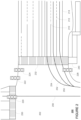
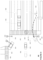
- FIGURE 2 is an example of detailed map information 200 for a section of roadway including an intersection 202.
- the detailed map information 200 includes information identifying the shape, location, and other characteristics of lane lines 210, 212, 214, traffic signal lights 220, 222, 224, 226, crosswalks 230, 232, and sidewalks 240.
- Each lane may be associated with a rail 250, 252, 254, 256 which indicates the direction in which a vehicle should generally travel in the respective lane. For example, a vehicle may follow rail 252 when driving in the lane between lane lines 210 and 212.
- the map information need not be entirely image based (for example, raster).
- the detailed map information may include one or more roadgraphs or graph networks of information such as roads, lanes, intersections, and the connections between these features.
- Each feature may be stored as graph data and may be associated with information such as a geographic location and whether or not it is linked to other related features, for example, a stop sign may be linked to a road and an intersection, etc.
- the associated data may include grid-based indices of a roadgraph to allow for efficient lookup of certain roadgraph features.
- the computing device 112 may use data from the positioning system 170, perception system 172, and the detailed map information in order to generate a future path or trajectory for the vehicle to achieve a mission goal, for example, by reaching a particular destination location.
- These trajectories may include specific locations or waypoints that should be reached by the vehicle at specific times into the future, but may include a set of waypoints without times, a set of directions (turn left, turn right, go straight, etc.), a set of images depicting what the system should see, etc. Together, these locations form a future trajectory for the vehicle.
- the computing device 112 may generate corresponding instructions for controlling various systems of the vehicle in order to maneuver the vehicle according to the trajectory, or rather in order to reach the specific locations at the specific times in the future.
- the computing system 110 may then send the trajectory and corresponding instructions to computing system 210.
- computing system 210 may also be a part of the autonomous driving computing system incorporated into vehicle 100, but may also be somewhat less complex than computing system 110.
- the computing system 210 may be sophisticated enough to maneuver the vehicle based on trajectories and corresponding instructions received from the computing system 110, but may lack the sophisticated perception and planning systems of the computing system 110.
- the computing system 210 may communicate with various other systems of the vehicle in order to control the heading and speed of the vehicle.
- the secondary computing system may receive or access location information from the positioning system 170 of computing system 110 as well as information from other systems related to the status of the vehicle, such as those which indicate the position of the wheels, what the brakes are doing, etc. This enables the computing system 210 to follow a particular trajectory as discussed below.
- computing device 210 may send to and receive information from a deceleration system 160 (for controlling braking of the vehicle or in some cases may simply include the brakes of the vehicle), acceleration system 162 (for controlling acceleration of the vehicle or in some cases may simply include controlling power to the engine), steering system 164 (for controlling the orientation of the wheels and direction of the vehicle), signaling system 166 (for controlling turn signals), and power system 174 (for example, a battery and/or gas or diesel powered engine) in order to control the movement, speed, etc. of vehicle 100 in accordance with the instructions 234 of memory 230 as well as other received input autonomously.
- the computing system 210 can control the vehicle without the need continuous or periodic input from a passenger of the vehicle.
- these systems are shown as external to computing device 210, in actuality, these systems may also be incorporated into computing device 210, again as an autonomous driving computing system for controlling vehicle 100.
- the computing device 210 may control the direction and speed of the vehicle by controlling various components according to the corresponding instructions of a given trajectory received from the computing system 110.
- computer 110 may cause the vehicle to accelerate (e.g., by increasing fuel or other energy provided to the engine by acceleration system 162), decelerate (e.g., by decreasing the fuel supplied to the engine, changing gears, and/or by applying brakes by deceleration system 160), change direction (e.g., by turning the front or rear wheels of vehicle 100 by steering system 164), and signal such changes (e.g., by lighting turn signals of signaling system 166).
- accelerate e.g., by increasing fuel or other energy provided to the engine by acceleration system 162
- decelerate e.g., by decreasing the fuel supplied to the engine, changing gears, and/or by applying brakes by deceleration system 160
- change direction e.g., by turning the front or rear wheels of vehicle 100 by steering system 164
- signal such changes e.g., by lighting turn signals
- the acceleration system 162 and deceleration system 162 may be a part of a drivetrain that includes various components between an engine of the vehicle and the wheels of the vehicle.
- computer 212 may also control the drivetrain of the vehicle in order to maneuver the vehicle autonomously.
- computing device 212 may interact with deceleration system 160 and acceleration system 162 in order to control the speed of the vehicle.
- steering system 164 may be used by computing device 110 in order to control the direction of vehicle 100.
- the steering system may include components to control the angle of wheels to turn the vehicle.
- Signaling system 166 may be used by computing device 212 in order to signal the vehicle's intent to other drivers or vehicles, for example, by lighting turn signals or brake lights when needed.
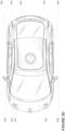
- FIGURES 3A-3D are examples of external views of vehicle 100.
- vehicle 100 includes many features of a typical vehicle such as headlights 302, windshield 303, taillights/turn signal lights 304, rear windshield 305, doors 306, side view mirrors 308, tires and wheels 310, and turn signal/parking lights 312.
- Headlights 302, taillights/turn signal lights 304, and turn signal/parking lights 312 may be associated the signaling system 166.
- Light bar 307 may also be associated with the signaling system 166.
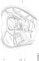
- FIGURE 4 is an example internal view of vehicle 100 through the opening of door 306.
- vehicle 100 does not include a steering wheel, gas (acceleration) pedal, or brake (deceleration) pedal which would allow for a semiautonomous or manual driving mode where a passenger would directly control the steering, acceleration and/or deceleration of the vehicle via the drivetrain.
- user input is limited to a microphone of the user input 150 (not shown), features of the console 404, and, if available, wireless network connections 156.
- internal electronic display 152 may merely provide information to the passenger and need not include a touch screen or other interface for user input.
- the internal electronic display 152 may include a touch screen or other user input device for entering information by a passenger such as a destination, etc.
- the vehicle may include a steering, acceleration and braking input that a passenger can use to control the vehicle in a manual or semi-autonomous driving mode.
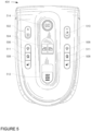
- FIGURE 5 is a top down view of the console 404.
- Console 404 includes various buttons for controlling features of vehicle 100.
- console 404 includes buttons that may be found in a typical vehicle such as buttons 502 for locking and unlocking the doors 306, buttons 504 for raising or lowering the windows of doors 306, buttons 506 for turning on internal lights of the vehicle, buttons 508 for controlling a heating function of seats 402, as well as buttons 510 for controlling the volume of speakers 154.
- console 404 also includes buttons 511 for initiating communication with a remote concierge via a wireless network connection if available.
- Buttons 512 and 514 may also be a part of user input 150 and in this regard, allow a passenger to communicate with computer 110, for example, to initiate or end a trip in the vehicle.
- button 512 may act as an emergency stopping button that, when pushed, causes vehicle 100 to stop in a short amount of time. Because the passenger does not have direct control of the acceleration or deceleration of vehicle 100 by way of a gas or brake pedal, button 512 may be an emergency stop button that is critical to allowing a passenger to feel safe and act quickly in case of an immediate emergency.
- Button 514 may be a multi-function button.
- button 514 may have three different states. In the first state, button 514 may be inactive, that is, if pressed, the vehicle's computer 110 would not respond by taking any particular action with regard to controlling the movement of the vehicle. In the second state, when the vehicle is ready to begin a trip, the button 514 may change to a "GO" button which a passenger uses to initiate a trip to a destination or drop off location. Once vehicle 100 is moving, button 514 may change to a third state, where the button 514 is a "PULL OVER" button which a passenger users to initiate a non-emergency stop. In this regard, computer 110 may respond by determining a reasonable place to pull the vehicle over, rather than coming to a more sudden stop as with the emergency stop button 512.
- passenger communication with computer 110 for navigation purposes may be limited to button 514, emergency stopping button 512, a short range wireless communication system (such as Bluetooth LE) with the passenger's client computing device, and by sending information from the passenger's client computing device to a remote server which then relays that information to the vehicle's computer.
- a passenger may provide information to the vehicle's computer 110 via voice commands though the microphone as discussed above.
- the passenger may communicate with the concierge via a phone call, an application on the passenger's client computing device, a microphone, and/or the concierge button 511 and in turn, the concierge may provide instructions control certain aspects of a vehicle via a concierge work station.
- FIGURES 6 and 7 are pictorial and functional diagrams, respectively, of an example system 600 that includes a plurality of computing devices 610, 620, 630, 640 and a storage system 650 connected via a network 660.
- System 600 also includes vehicle 100, and vehicle 100A which may be configured similarly to vehicle 100. Although only a few vehicles and computing devices are depicted for simplicity, a typical system may include significantly more.
- each of computing devices 610, 620, 630, 640 may include one or more processors, memory, data and instructions. Such processors, memories, data and instructions may be configured similarly to one or more processors 120, memory 130, data 132, and instructions 134 of computing device 110.
- the network 660 may include various configurations and protocols including short range communication protocols such as Bluetooth, Bluetooth LE, the Internet, World Wide Web, intranets, virtual private networks, wide area networks, local networks, private networks using communication protocols proprietary to one or more companies, Ethernet, WiFi and HTTP, and various combinations of the foregoing.
- short range communication protocols such as Bluetooth, Bluetooth LE, the Internet, World Wide Web, intranets, virtual private networks, wide area networks, local networks, private networks using communication protocols proprietary to one or more companies, Ethernet, WiFi and HTTP, and various combinations of the foregoing.
- Such communication may be facilitated by any device capable of transmitting data to and from other computing devices, such as modems and wireless interfaces.
- one or more computing devices 110 may include a server having a plurality of computing devices, e.g., a load balanced server farm, that exchange information with different nodes of a network for the purpose of receiving, processing and transmitting the data to and from other computing devices.
- one or more computing devices 210 may include one or more server computing devices that are capable of communicating with one or more computing devices 110 of vehicle 100 or a similar computing device of vehicle 100A as well as client computing devices 620, 630, 640 via the network 660.
- vehicles 100 and 100A may be a part of a fleet of vehicles that can be dispatched by server computing devices to various locations. In this regard, the vehicles of the fleet may periodically send the server computing devices location information provided by the vehicle's respective positioning systems and the one or more server computing devices may track the locations of the vehicles.
- server computing devices 610 may use network 660 to transmit and present information to a user, such as user 622, 632, 642 on a display, such as displays 624, 634, 644 of computing devices 620, 630, 640.
- computing devices 620, 630, 640 may be considered client computing devices.
- each client computing device 620, 630, 640 may be a personal computing device intended for use by a user 622, 632, 642, and have all of the components normally used in connection with a personal computing device including a one or more processors (e.g., a central processing unit (CPU)), memory (e.g., RAM and internal hard drives) storing data and instructions, a display such as displays 624, 634, 644 (e.g., a monitor having a screen, a touch-screen, a projector, a television, or other device that is operable to display information), and user input devices 626, 636, 646 (e.g., a mouse, keyboard, touch-screen or microphone).
- the client computing devices may also include a camera for recording video streams, speakers, a network interface device, and all of the components used for connecting these elements to one another.
- client computing devices 620, 630, and 640 may each comprise a full-sized personal computing device, they may alternatively comprise mobile computing devices capable of wirelessly exchanging data with a server over a network such as the Internet.
- client computing device 620 may be a mobile phone or a device such as a wireless-enabled PDA, a tablet PC, a wearable computing device or system, or a netbook that is capable of obtaining information via the Internet or other networks.
- client computing device 630 may be a wearable computing system, shown as a head-mounted computing system in FIGURE 7 .
- the user may input information using a small keyboard, a keypad, microphone, using visual signals with a camera, or a touch screen.
- client computing device 640 may be concierge work station used by an administrator to provide concierge services to users such as users 622 and 632.
- a concierge 642 may use the concierge work station 640 to communicate via a telephone call or audio connection with users through their respective client computing devices or vehicles 100 or 100A in order to ensure the safe operation of vehicles 100 and 100A and the safety of the users as described in further detail below.
- FIGURES 6 and 7 any number of such work stations may be included in a typical system.
- the storage system 650 may also store routing data for generating and evaluating routes between locations.
- the routing information may be used to estimate how long it would take a vehicle at a first location to reach a second location.
- the routing information may include map information, not necessarily as particular as the detailed map information described above, but including roads, as well as information about those road such as direction (one way, two way, etc.), orientation (North, South, etc.), speed limits, as well as traffic information identifying expected traffic conditions, etc.
- storage system 250 can be of any type of computerized storage capable of storing information accessible by the server computing devices 610, such as a hard-drive, memory card, ROM, RAM, DVD, CD-ROM, write-capable, and read-only memories.
- storage system 650 may include a distributed storage system where data is stored on a plurality of different storage devices which may be physically located at the same or different geographic locations.
- Storage system 650 may be connected to the computing devices via the network 660 as shown in FIGURE 6 and/or may be directly connected to or incorporated into any of the computing devices 110, 610, 620, 630, 640, etc.
- a user may download an application for requesting a vehicle to a client computing device.
- users 622 and 632 may download the application via a link in an email, directly from a website, or an application store to client computing devices 620 and 630.
- client computing device may transmit a request for the application over the network, for example, to one or more server computing devices 610, and in response, receive the application.
- the application may be installed locally at the client computing device.
- Sensors associated with the seats, doors, and seatbelts may be used to determine if the passenger has complied. Once the passenger has complied with the instructions, he or she may press or otherwise activate button 514. In response, the computer 110 may initiate the necessary systems to control the vehicle autonomously along a route to the destination location.
- this may include communicating with the deceleration system 160, acceleration system 162, steering system 164, signaling system 166 (for controlling turn signals), and power system 174 in order to control the movement, speed, etc. of vehicle 100 in accordance with the instructions 234 of memory 230 as well as the corresponding instructions.
- the computing system 210 would then control the vehicle according to the updated trajectory and corresponding instructions until a new updated trajectory and corresponding instructions are received, and so on until the mission goal is achieved.
- This threshold point may be determined by measuring a predetermined threshold period of time from the time when the fall back trajectory was received by the computing system 210. Similarly, the threshold point may be determined by measuring a predetermined threshold distance from the location of the vehicle when the fall back trajectory was received by the computing system 210. The threshold point may also correspond to a point in time or space on the fall back trajectory where it would begin to diverge from the nominal trajectory, or, in the example 900 of FIGURE 9 , at point 940.
- the threshold point may be determined dynamically by the computing systems 110 and/or 210, for instance, based on the vehicle's speed or steering angle. For instance, the threshold point may occur sooner when the vehicle is driving straight as opposed to when the vehicle is turning its wheels in the direction of where the vehicle would need to stop according to the fall back trajectory. Similarly, the threshold point may occur sooner when the vehicle is driving at 32 km (20 miles) per hour than if the vehicle were traveling at 8 km (5 miles) per hour as it would take less time to stop the vehicle at 8 km (5 miles) per hour. Of course, the threshold point may thus be dependent not only on the vehicle's speed and steering angle, but also the characteristics of the roadway as identified from the detailed map information or sensor data from the perception system.
- threshold point may also correspond to a point (in time or space) on the fall back trajectory that is after the point of divergence between the fall back and nominal trajectories.
- the computing system 210 may tolerate a small amount of divergence between the trajectories and still return to the primary trajectory when an updated trajectory is received. However, after a significant amount of divergence, it could be unsafe to return to the primary trajectory (or a new updated fall back trajectory).
- the computing system 210 would not need to switch to a new trajectory and new corresponding instructions, but would simply continue controlling the vehicle using the last received fall back trajectory and corresponding instructions as discussed above. As this trajectory is a fall back trajectory, the computing system 210 would therefore maneuver the vehicle to stop safely.
- the secondary computing system may include a rudimentary perception system.
- This perception system may include one of the sensors of the primary computing system's perception system or a dedicated sensor for the secondary computing system.
- a forward-facing radar could be used to monitor objects directly in front of the vehicle.
- this sensor may simply be used by the vehicle simply as a last resort option to apply the brakes as much as possible where an object is detected within a certain distance of the vehicle.
- the sensor may be configured to filter many different types of objects, for example, based on distance and speed of the object and/or vehicle.
- FIGURE 11 is an example flow diagram 1100 of various of the aspects described above which may be performed by one or more processors of a secondary computing system such as computing system 210.
- a fall back trajectory from a location of the vehicle in order to safely stop the vehicle is received by the one or more processors of the secondary computing system.
- a portion of the fall back trajectory from the location of the vehicle to a divergent location is identical to a portion of a nominal trajectory from the location of the vehicle to the divergent location.
- the nominal trajectory allows the vehicle to achieve a mission goal, and the nominal trajectory and the fall back trajectory diverge after the divergent location.
- the vehicle is controlled by the one or more processors of the secondary computing system, according to the portion of the fall back trajectory in order to achieve the mission goal.
- the one or more processors of the secondary computing system wait for an updated trajectory from the primary computing system while controlling the vehicle at block 1106.
- the vehicle reaches a threshold point on the fall back trajectory and an updated trajectory has not yet been received by the one or more processors of the secondary computing system
- the one or more processors of the secondary computing system continue to control the vehicle according to the fall back trajectory in order to safely stop the vehicle at block 1108.
- the one or more processors of the secondary computing system ignore the updated trajectory.
Landscapes
- Engineering & Computer Science (AREA)
- Automation & Control Theory (AREA)
- Radar, Positioning & Navigation (AREA)
- Remote Sensing (AREA)
- Physics & Mathematics (AREA)
- General Physics & Mathematics (AREA)
- Aviation & Aerospace Engineering (AREA)
- Transportation (AREA)
- Mechanical Engineering (AREA)
- Human Computer Interaction (AREA)
- Business, Economics & Management (AREA)
- Health & Medical Sciences (AREA)
- Artificial Intelligence (AREA)
- Evolutionary Computation (AREA)
- Game Theory and Decision Science (AREA)
- Medical Informatics (AREA)
- Traffic Control Systems (AREA)
- Control Of Driving Devices And Active Controlling Of Vehicle (AREA)
- Control Of Position, Course, Altitude, Or Attitude Of Moving Bodies (AREA)
- Navigation (AREA)
- Regulating Braking Force (AREA)
- Electric Propulsion And Braking For Vehicles (AREA)
Claims (5)
- Procédé comprenant :la réception, par un ou plusieurs processeurs (220) d'un système informatique secondaire (210) à partir d'un système informatique primaire (110), d'une trajectoire de repli à partir d'un emplacement d'un véhicule (100) afin d'arrêter le véhicule en toute sécurité, dans lequel une partie de la trajectoire de repli depuis l'emplacement du véhicule jusqu'à un emplacement divergent est identique à une partie d'une trajectoire nominale depuis l'emplacement du véhicule jusqu'à l'emplacement divergent, la trajectoire nominale permet au véhicule d'atteindre un objectif de mission, et la trajectoire nominale et la trajectoire de repli divergent après l'emplacement divergent ;la commande, par les un ou plusieurs processeurs du système informatique secondaire, du véhicule selon la partie de la trajectoire de repli afin d'atteindre l'objectif de mission ;l'attente, par les un ou plusieurs processeurs du système informatique secondaire, d'une trajectoire actualisée à partir du système informatique primaire tout en commandant le véhicule ; etlorsqu'une trajectoire actualisée n'a pas été reçue par les un ou plusieurs processeurs du système informatique secondaire et le véhicule atteint un point seuil de la trajectoire de repli, la poursuite, par les un ou plusieurs processeurs du système informatique secondaire, de la commande du véhicule selon la trajectoire de repli afin d'arrêter le véhicule en toute sécurité.
- Procédé selon la revendication 1, comprenant en outre, lorsqu'une trajectoire actualisée est reçue après que le point de seuil est atteint, la poursuite, par les un ou plusieurs processeurs du système informatique secondaire, de la commande du véhicule selon la trajectoire de repli.
- Support non transitoire lisible par ordinateur incluant des instructions qui, lorsqu'elles sont exécutées par les un ou plusieurs processeurs du système informatique secondaire, amènent les un ou plusieurs processeurs à réaliser le procédé de la revendication 1 ou 2.
- Système de commande d'un véhicule (100), le système comprenant :
un ou plusieurs processeurs (220) d'un système informatique secondaire (210) configurés pour :recevoir, à partir d'un système informatique primaire (110), une trajectoire de repli à partir d'un emplacement d'un véhicule afin d'arrêter le véhicule en toute sécurité, dans lequel une partie de la trajectoire de repli depuis l'emplacement du véhicule jusqu'à un emplacement divergent est identique à une partie d'une trajectoire nominale depuis l'emplacement du véhicule jusqu'à l'emplacement divergent, la trajectoire nominale permet au véhicule d'atteindre un objectif de mission, et la trajectoire nominale et la trajectoire de repli divergent après l'emplacement divergent ;commander le véhicule selon la partie de la trajectoire de repli afin d'atteindre l'objectif de mission ;attendre une trajectoire actualisée à partir du système informatique primaire tout en commandant le véhicule ; etlorsqu'une trajectoire actualisée n'a pas été reçue par les un ou plusieurs processeurs et le véhicule atteint un point seuil de la trajectoire de repli, poursuivre la commande du véhicule selon la trajectoire de repli afin d'arrêter le véhicule en toute sécurité. - Système selon la revendication 4, dans lequel les uns ou plusieurs processeurs sont en outre configurés pour, lorsqu'une trajectoire actualisée est reçue après que le point de seuil est atteint, poursuivre la commande du véhicule selon la trajectoire de repli.
Applications Claiming Priority (4)
| Application Number | Priority Date | Filing Date | Title |
|---|---|---|---|
| US14/991,150 US9551992B1 (en) | 2016-01-08 | 2016-01-08 | Fall back trajectory systems for autonomous vehicles |
| US15/371,595 US9740202B2 (en) | 2016-01-08 | 2016-12-07 | Fall back trajectory systems for autonomous vehicles |
| PCT/US2016/068233 WO2017120057A1 (fr) | 2016-01-08 | 2016-12-22 | Systèmes de trajectoire de repli pour véhicules autonomes |
| EP16884203.7A EP3380904B1 (fr) | 2016-01-08 | 2016-12-22 | Systèmes de trajectoire de repli pour véhicules autonomes |
Related Parent Applications (2)
| Application Number | Title | Priority Date | Filing Date |
|---|---|---|---|
| EP16884203.7A Division-Into EP3380904B1 (fr) | 2016-01-08 | 2016-12-22 | Systèmes de trajectoire de repli pour véhicules autonomes |
| EP16884203.7A Division EP3380904B1 (fr) | 2016-01-08 | 2016-12-22 | Systèmes de trajectoire de repli pour véhicules autonomes |
Publications (2)
| Publication Number | Publication Date |
|---|---|
| EP3705973A1 EP3705973A1 (fr) | 2020-09-09 |
| EP3705973B1 true EP3705973B1 (fr) | 2025-03-26 |
Family
ID=59274374
Family Applications (2)
| Application Number | Title | Priority Date | Filing Date |
|---|---|---|---|
| EP16884203.7A Active EP3380904B1 (fr) | 2016-01-08 | 2016-12-22 | Systèmes de trajectoire de repli pour véhicules autonomes |
| EP20171529.9A Active EP3705973B1 (fr) | 2016-01-08 | 2016-12-22 | Systèmes de trajectoire de repli pour véhicules autonomes |
Family Applications Before (1)
| Application Number | Title | Priority Date | Filing Date |
|---|---|---|---|
| EP16884203.7A Active EP3380904B1 (fr) | 2016-01-08 | 2016-12-22 | Systèmes de trajectoire de repli pour véhicules autonomes |
Country Status (9)
| Country | Link |
|---|---|
| US (1) | US9740202B2 (fr) |
| EP (2) | EP3380904B1 (fr) |
| JP (2) | JP6488428B1 (fr) |
| KR (2) | KR101958430B1 (fr) |
| CN (2) | CN108475055B (fr) |
| AU (2) | AU2016384627B2 (fr) |
| CA (1) | CA3010882C (fr) |
| SG (1) | SG11201805625YA (fr) |
| WO (1) | WO2017120057A1 (fr) |
Families Citing this family (68)
| Publication number | Priority date | Publication date | Assignee | Title |
|---|---|---|---|---|
| KR101745161B1 (ko) * | 2015-10-28 | 2017-06-08 | 현대자동차주식회사 | 목적지 유형에 따른 차량의 제어 방법 |
| CN108604419B (zh) * | 2016-01-29 | 2021-02-09 | 日产自动车株式会社 | 车辆的行驶控制方法及车辆的行驶控制装置 |
| US9990846B1 (en) * | 2017-02-07 | 2018-06-05 | NoTraffic Ltd. | Device, system and method for traffic management |
| US10156849B1 (en) * | 2017-06-30 | 2018-12-18 | Uber Technologies, Inc. | Human supervision of an automated driving system |
| DE112017007756T5 (de) * | 2017-08-16 | 2020-04-09 | Ford Global Technologies, Llc | Bestätigung des Einstiegs in ein Fahrzeug |
| US10620634B2 (en) * | 2017-08-23 | 2020-04-14 | Uatc, Llc | Vehicle interface for autonomous vehicle |
| US10569784B2 (en) * | 2017-09-28 | 2020-02-25 | Waymo Llc | Detecting and responding to propulsion and steering system errors for autonomous vehicles |
| US20190129413A1 (en) * | 2017-10-26 | 2019-05-02 | GM Global Technology Operations LLC | Flexible remote vehicle control |
| JP6525413B1 (ja) * | 2017-12-28 | 2019-06-05 | マツダ株式会社 | 車両制御装置 |
| US10583839B2 (en) * | 2017-12-28 | 2020-03-10 | Automotive Research & Testing Center | Method of lane change decision-making and path planning |
| US10585434B2 (en) * | 2018-01-10 | 2020-03-10 | GM Global Technology Operations LLC | Relaxable turn boundaries for autonomous vehicles |
| US10816977B2 (en) | 2018-01-26 | 2020-10-27 | Baidu Usa Llc | Path and speed optimization fallback mechanism for autonomous vehicles |
| WO2019201412A1 (fr) * | 2018-04-16 | 2019-10-24 | Volvo Truck Corporation | Procédé pour une chaîne de véhicules |
| US11511746B2 (en) * | 2018-05-11 | 2022-11-29 | Volvo Truck Corporation | Method for establishing a path for a vehicle |
| EP3865822B1 (fr) * | 2018-05-15 | 2024-10-02 | Mobileye Vision Technologies Ltd. | Systèmes et procédés de navigation de véhicule autonome |
| EP3794571A4 (fr) | 2018-05-16 | 2022-01-26 | Notraffic Ltd. | Système et procédé d'utilisation d'une communication v2x et de données de capteurs |
| US11022452B2 (en) * | 2018-05-21 | 2021-06-01 | Waymo Llc | Inconvenience for passenger pickups and drop offs for autonomous vehicles |
| US10564641B2 (en) | 2018-07-20 | 2020-02-18 | May Mobility, Inc. | Multi-perspective system and method for behavioral policy selection by an autonomous agent |
| US10614709B2 (en) | 2018-07-24 | 2020-04-07 | May Mobility, Inc. | Systems and methods for implementing multimodal safety operations with an autonomous agent |
| JP7073987B2 (ja) | 2018-08-31 | 2022-05-24 | トヨタ自動車株式会社 | 同行車両選択システム |
| US11543824B2 (en) * | 2018-10-09 | 2023-01-03 | Waymo Llc | Queueing into pickup and drop-off locations |
| US10969470B2 (en) | 2019-02-15 | 2021-04-06 | May Mobility, Inc. | Systems and methods for intelligently calibrating infrastructure devices using onboard sensors of an autonomous agent |
| CN110243368A (zh) * | 2019-04-29 | 2019-09-17 | 丰疆智能科技研究院(常州)有限公司 | 智能农机的行驶轨迹建立系统及其应用 |
| WO2020240274A1 (fr) * | 2019-05-28 | 2020-12-03 | Mobileye Vision Technologies Ltd. | Systèmes et procédés de navigation de véhicule |
| TWI710489B (zh) | 2019-07-08 | 2020-11-21 | 宏碁股份有限公司 | 車輛及車輛控制方法 |
| CN112298197B (zh) * | 2019-07-26 | 2022-05-31 | 宏碁股份有限公司 | 车辆及车辆控制方法 |
| US11292457B2 (en) | 2019-07-31 | 2022-04-05 | Toyota Research Institute, Inc. | Autonomous vehicle user interface with predicted trajectories |
| US11292458B2 (en) | 2019-07-31 | 2022-04-05 | Toyota Research Institute, Inc. | Autonomous vehicle user interface with predicted trajectories |
| US11328593B2 (en) | 2019-07-31 | 2022-05-10 | Toyota Research Institute, Inc. | Autonomous vehicle user interface with predicted trajectories |
| EP3792125B1 (fr) * | 2019-09-13 | 2023-12-06 | Zenuity AB | Suivi de trajectoire sécurisé dans des environnements incertains |
| JP7230777B2 (ja) * | 2019-11-11 | 2023-03-01 | トヨタ自動車株式会社 | 車両制御システム |
| US11345360B1 (en) * | 2019-12-12 | 2022-05-31 | Zoox, Inc. | Localization error handling |
| JP7258737B2 (ja) * | 2019-12-18 | 2023-04-17 | 株式会社クボタ | 作業車両 |
| US20210200211A1 (en) * | 2019-12-31 | 2021-07-01 | Baidu Usa Llc | Method of generating back-up trajectories for self-driving vehicles during emergency |
| CN115023380B (zh) | 2020-01-31 | 2026-02-24 | 采埃孚商用车系统全球有限公司 | 非对称性的故障安全的系统结构 |
| JP7318576B2 (ja) * | 2020-03-18 | 2023-08-01 | トヨタ自動車株式会社 | 情報処理装置、情報処理システム、プログラム、及び車両 |
| EP3885226B1 (fr) * | 2020-03-25 | 2024-08-14 | Aptiv Technologies AG | Procédé et système de planification du mouvement d'un véhicule |
| KR102176483B1 (ko) * | 2020-03-30 | 2020-11-09 | 한양대학교 산학협력단 | 차선 정보를 래스터화하여 활용하는 딥러닝 기반 차량 경로 예측 방법 및 장치 |
| US11181917B2 (en) * | 2020-04-15 | 2021-11-23 | Baidu Usa Llc | Path planning system based on steering wheel self zeroing for autonomous vehicles |
| WO2022006418A1 (fr) | 2020-07-01 | 2022-01-06 | May Mobility, Inc. | Procédé et système de gestion dynamique d'interventions de véhicule autonome |
| CN112224186B (zh) * | 2020-09-18 | 2025-03-21 | 珠海广通汽车有限公司 | 车辆的控制方法、装置、计算机可读存储介质和处理器 |
| US12204335B2 (en) * | 2020-11-30 | 2025-01-21 | Y.E. Hub Armenia LLC | Systems and methods for controlling a robotic vehicle |
| US11807266B2 (en) * | 2020-12-04 | 2023-11-07 | Mitsubishi Electric Corporation | Driving system for distribution of planning and control functionality between vehicle device and cloud computing device, vehicle computing device, and cloud computing device |
| JP7405067B2 (ja) * | 2020-12-11 | 2023-12-26 | トヨタ自動車株式会社 | 車両の制御装置、及び車両の制御方法 |
| EP4260009A4 (fr) * | 2020-12-14 | 2024-11-20 | May Mobility, Inc. | Système et procédé de plateforme de sécurité de véhicule autonome |
| EP4264181A4 (fr) | 2020-12-17 | 2024-10-30 | May Mobility, Inc. | Procédé et système de mise à jour dynamique d'une représentation environnementale d'un agent autonome |
| US11654932B2 (en) | 2020-12-28 | 2023-05-23 | Waymo Llc | Architecture for variable motion control envelope |
| US12032378B2 (en) * | 2021-01-12 | 2024-07-09 | Apple Inc. | Automation control using stop trajectories |
| US20220266862A1 (en) * | 2021-02-25 | 2022-08-25 | Autonomous Solutions, Inc. | Intelligent urgent stop system for an autonomous vehicle |
| EP4314708A4 (fr) | 2021-04-02 | 2024-12-25 | May Mobility, Inc. | Procédé et système pour faire fonctionner un agent autonome avec des informations environnementales incomplètes |
| WO2022256249A1 (fr) | 2021-06-02 | 2022-12-08 | May Mobility, Inc. | Procédé et système d'assistance à distance d'un agent autonome |
| US11891078B1 (en) | 2021-09-29 | 2024-02-06 | Zoox, Inc. | Vehicle operating constraints |
| US12017668B1 (en) | 2021-09-29 | 2024-06-25 | Zoox, Inc. | Limited vehicular operation with a faulted component |
| US11891076B1 (en) * | 2021-09-29 | 2024-02-06 | Zoox, Inc. | Manual operation vehicle constraints |
| WO2023102098A1 (fr) | 2021-12-01 | 2023-06-08 | May Mobility, Inc. | Procédé et système pour le fonctionnement basé sur l'impact d'un agent autonome |
| US12296849B2 (en) | 2021-12-02 | 2025-05-13 | May Mobility, Inc. | Method and system for feasibility-based operation of an autonomous agent |
| JP7698060B2 (ja) * | 2021-12-07 | 2025-06-24 | Astemo株式会社 | 車両制御装置、車両制御方法、及び車両制御システム |
| KR102418566B1 (ko) * | 2021-12-22 | 2022-07-08 | 재단법인 지능형자동차부품진흥원 | 엣지 인프라 기반의 자율 주행 안전 제어 시스템 및 방법 |
| JP7851524B2 (ja) | 2022-02-14 | 2026-04-27 | メイ モビリティー,インコーポレイテッド | 自律エージェントの条件付き動作のための方法及びシステム |
| US11673565B1 (en) * | 2022-06-30 | 2023-06-13 | Plusai, Inc. | Recoverable fail-safe trajectory |
| US20240011781A1 (en) * | 2022-07-08 | 2024-01-11 | Argo AI, LLC | Method and system for asynchronous negotiation of autonomous vehicle stop locations |
| US20240017738A1 (en) * | 2022-07-12 | 2024-01-18 | Waymo Llc | Planning trajectories for controlling autonomous vehicles |
| JP2026500243A (ja) | 2022-12-13 | 2026-01-06 | メイ モビリティー,インコーポレイテッド | 自律車両が遭遇し得るリスクを評価し軽減するための方法およびシステム |
| US20250002047A1 (en) * | 2023-06-30 | 2025-01-02 | Zoox, Inc. | Trajectory selection in response to triggering events |
| EP4575797A4 (fr) * | 2023-10-23 | 2026-02-25 | Lg Electronics Inc | Dispositif de traitement de signal et dispositif d'affichage de véhicule le comprenant |
| JP7845331B2 (ja) * | 2023-10-24 | 2026-04-14 | トヨタ自動車株式会社 | 車両制御装置及びプログラム |
| CN118907131A (zh) * | 2024-08-20 | 2024-11-08 | Xg科技私人有限公司 | 车辆控制方法、装置、存储介质及电子设备 |
| CN119773794B (zh) * | 2025-01-17 | 2025-10-17 | 上海友道智途科技有限公司 | 一种汽车自动驾驶系统及行为安全方法 |
Family Cites Families (35)
| Publication number | Priority date | Publication date | Assignee | Title |
|---|---|---|---|---|
| JPH07120202B2 (ja) * | 1987-03-14 | 1995-12-20 | 株式会社豊田自動織機製作所 | 無人車の運行制御装置 |
| US6393362B1 (en) * | 2000-03-07 | 2002-05-21 | Modular Mining Systems, Inc. | Dynamic safety envelope for autonomous-vehicle collision avoidance system |
| US6442456B2 (en) * | 2000-03-07 | 2002-08-27 | Modular Mining Systems, Inc. | Anti-rut system for autonomous-vehicle guidance |
| JP2006126107A (ja) * | 2004-11-01 | 2006-05-18 | Nissan Motor Co Ltd | ナビゲーションシステムを用いた退避誘導システム |
| US8126642B2 (en) * | 2008-10-24 | 2012-02-28 | Gray & Company, Inc. | Control and systems for autonomously driven vehicles |
| JP5218667B2 (ja) * | 2009-10-22 | 2013-06-26 | トヨタ自動車株式会社 | 走行制御装置 |
| US8700327B2 (en) | 2010-04-27 | 2014-04-15 | Honda Motor Co., Ltd. | Method of determining routes for use in navigation |
| US8260482B1 (en) * | 2010-04-28 | 2012-09-04 | Google Inc. | User interface for displaying internal state of autonomous driving system |
| JP2011240816A (ja) * | 2010-05-18 | 2011-12-01 | Denso Corp | 自律走行制御装置 |
| US8509982B2 (en) * | 2010-10-05 | 2013-08-13 | Google Inc. | Zone driving |
| US9601020B2 (en) * | 2010-10-05 | 2017-03-21 | Toyota Jidosha Kabushiki Kaisha | Collision determination device |
| AU2012302054B2 (en) | 2011-08-29 | 2014-11-13 | Crown Equipment Corporation | Vehicular navigation control interface |
| DE102011083944A1 (de) * | 2011-10-04 | 2013-04-04 | Robert Bosch Gmbh | Verfahren zum Aktivieren eines Fahrerassistenzsystems |
| DE102011086336A1 (de) * | 2011-11-15 | 2013-05-16 | Robert Bosch Gmbh | Vorrichtung und verfahren zum betreiben eines fahrzeugs |
| US8855847B2 (en) | 2012-01-20 | 2014-10-07 | Toyota Motor Engineering & Manufacturing North America, Inc. | Intelligent navigation system |
| JP5446055B2 (ja) * | 2012-01-27 | 2014-03-19 | 村田機械株式会社 | 台車システム |
| US9180890B2 (en) * | 2012-02-27 | 2015-11-10 | Ford Global Technologies | Smart adaptive cruise control |
| US8880272B1 (en) * | 2012-03-16 | 2014-11-04 | Google Inc. | Approach for estimating the geometry of roads and lanes by using vehicle trajectories |
| US9495874B1 (en) * | 2012-04-13 | 2016-11-15 | Google Inc. | Automated system and method for modeling the behavior of vehicles and other agents |
| US9020757B2 (en) * | 2012-05-11 | 2015-04-28 | Trimble Navigation Limited | Path planning autopilot |
| US9120485B1 (en) * | 2012-09-14 | 2015-09-01 | Google Inc. | Methods and systems for smooth trajectory generation for a self-driving vehicle |
| DE102012217002A1 (de) * | 2012-09-21 | 2014-03-27 | Robert Bosch Gmbh | Verfahren und Vorrichtung zum Betreiben eines Kraftfahrzeugs in einem automatisierten Fahrbetrieb |
| EP2722687B1 (fr) | 2012-10-22 | 2015-04-29 | Sick Ag | Dispositif de sécurité pour un véhicule |
| US8825258B2 (en) * | 2012-11-30 | 2014-09-02 | Google Inc. | Engaging and disengaging for autonomous driving |
| DE102013213171A1 (de) * | 2013-07-04 | 2015-01-08 | Robert Bosch Gmbh | Verfahren und Vorrichtung zum Betreiben eines Kraftfahrzeugs in einem automatisierten Fahrbetrieb |
| DE102013213169A1 (de) * | 2013-07-04 | 2015-01-08 | Robert Bosch Gmbh | Verfahren und Vorrichtung zum Betreiben eines Kraftfahrzeugs in einem automatisierten Fahrbetrieb |
| KR101470190B1 (ko) * | 2013-07-09 | 2014-12-05 | 현대자동차주식회사 | 자율주행 시스템의 고장 처리 장치 및 그 방법 |
| DE102013013867A1 (de) * | 2013-08-20 | 2015-03-12 | Audi Ag | Kraftfahrzeug und Verfahren zur Steuerung eines Kraftfahrzeugs |
| EP2848488B2 (fr) * | 2013-09-12 | 2022-04-13 | Volvo Car Corporation | Procédé et agencement pour avertissement de transfert de commande dans un véhicule possédant des capacités de conduite autonome |
| US9212926B2 (en) * | 2013-11-22 | 2015-12-15 | Ford Global Technologies, Llc | In-vehicle path verification |
| US9405293B2 (en) * | 2014-05-30 | 2016-08-02 | Nissan North America, Inc | Vehicle trajectory optimization for autonomous vehicles |
| ES2879962T3 (es) * | 2014-12-10 | 2021-11-23 | Gogoro Inc | Sistemas y métodos de frenado regenerativo adaptativo y prevención de colisiones para vehículos accionados eléctricamente |
| CN104843000B (zh) * | 2015-02-14 | 2017-05-17 | 黄华 | 一种车辆自动驾驶系统及方法 |
| CN204679856U (zh) * | 2015-02-14 | 2015-09-30 | 黄华 | 一种车辆自动驾驶系统 |
| EP3232286B1 (fr) * | 2016-04-15 | 2018-12-26 | Volvo Car Corporation | Dispositif et procédé d'arrêt de sécurité d'un véhicule routier autonome |
-
2016
- 2016-12-07 US US15/371,595 patent/US9740202B2/en active Active
- 2016-12-22 KR KR1020187022507A patent/KR101958430B1/ko not_active Expired - Fee Related
- 2016-12-22 EP EP16884203.7A patent/EP3380904B1/fr active Active
- 2016-12-22 KR KR1020197006924A patent/KR102114199B1/ko active Active
- 2016-12-22 CN CN201680078191.0A patent/CN108475055B/zh active Active
- 2016-12-22 WO PCT/US2016/068233 patent/WO2017120057A1/fr not_active Ceased
- 2016-12-22 SG SG11201805625YA patent/SG11201805625YA/en unknown
- 2016-12-22 JP JP2018535290A patent/JP6488428B1/ja not_active Expired - Fee Related
- 2016-12-22 AU AU2016384627A patent/AU2016384627B2/en not_active Ceased
- 2016-12-22 CN CN202110576128.2A patent/CN113212457B/zh active Active
- 2016-12-22 CA CA3010882A patent/CA3010882C/fr active Active
- 2016-12-22 EP EP20171529.9A patent/EP3705973B1/fr active Active
-
2019
- 2019-02-25 JP JP2019031358A patent/JP6775046B2/ja active Active
-
2020
- 2020-01-15 AU AU2020200302A patent/AU2020200302B2/en active Active
Also Published As
| Publication number | Publication date |
|---|---|
| EP3380904B1 (fr) | 2020-06-03 |
| CN108475055A (zh) | 2018-08-31 |
| SG11201805625YA (en) | 2018-07-30 |
| KR20190027966A (ko) | 2019-03-15 |
| EP3705973A1 (fr) | 2020-09-09 |
| AU2016384627B2 (en) | 2019-11-21 |
| CA3010882C (fr) | 2019-11-12 |
| JP6775046B2 (ja) | 2020-10-28 |
| JP2019510285A (ja) | 2019-04-11 |
| EP3380904A4 (fr) | 2018-12-05 |
| CN113212457B (zh) | 2024-08-02 |
| CA3010882A1 (fr) | 2017-07-13 |
| JP2019096354A (ja) | 2019-06-20 |
| WO2017120057A1 (fr) | 2017-07-13 |
| US20170199523A1 (en) | 2017-07-13 |
| CN108475055B (zh) | 2021-06-11 |
| AU2016384627A1 (en) | 2018-07-19 |
| US9740202B2 (en) | 2017-08-22 |
| KR101958430B1 (ko) | 2019-03-14 |
| AU2020200302B2 (en) | 2020-10-08 |
| AU2020200302A1 (en) | 2020-02-06 |
| JP6488428B1 (ja) | 2019-03-20 |
| CN113212457A (zh) | 2021-08-06 |
| KR20180091951A (ko) | 2018-08-16 |
| KR102114199B1 (ko) | 2020-05-25 |
| EP3380904A1 (fr) | 2018-10-03 |
Similar Documents
| Publication | Publication Date | Title |
|---|---|---|
| AU2020200302B2 (en) | Fall back trajectory systems for autonomous vehicles | |
| US9551992B1 (en) | Fall back trajectory systems for autonomous vehicles | |
| US11914377B1 (en) | Autonomous vehicle behavior when waiting for passengers | |
| US11634134B2 (en) | Using discomfort for speed planning in responding to tailgating vehicles for autonomous vehicles | |
| KR102379392B1 (ko) | 자율 차량들을 위한 다수의 주행 모드들 | |
| EP3673339B1 (fr) | Arrêt sensible au contexte pour véhicules autonomes | |
| EP3649026B1 (fr) | Identification de passagers non affectés pour véhicules autonomes | |
| US10627825B2 (en) | Using discomfort for speed planning in autonomous vehicles | |
| US10640111B1 (en) | Speed planning for autonomous vehicles | |
| US20190155283A1 (en) | Determining pullover locations for autonomous vehicles | |
| JP2019537530A (ja) | 自律走行車の停車位置のプランニング | |
| CA3094795C (fr) | Utilisation d'inconfort pour une programmation de vitesse de vehicules autonomes |
Legal Events
| Date | Code | Title | Description |
|---|---|---|---|
| PUAI | Public reference made under article 153(3) epc to a published international application that has entered the european phase |
Free format text: ORIGINAL CODE: 0009012 |
|
| STAA | Information on the status of an ep patent application or granted ep patent |
Free format text: STATUS: THE APPLICATION HAS BEEN PUBLISHED |
|
| AC | Divisional application: reference to earlier application |
Ref document number: 3380904 Country of ref document: EP Kind code of ref document: P |
|
| AK | Designated contracting states |
Kind code of ref document: A1 Designated state(s): AL AT BE BG CH CY CZ DE DK EE ES FI FR GB GR HR HU IE IS IT LI LT LU LV MC MK MT NL NO PL PT RO RS SE SI SK SM TR |
|
| STAA | Information on the status of an ep patent application or granted ep patent |
Free format text: STATUS: REQUEST FOR EXAMINATION WAS MADE |
|
| 17P | Request for examination filed |
Effective date: 20210225 |
|
| RBV | Designated contracting states (corrected) |
Designated state(s): AL AT BE BG CH CY CZ DE DK EE ES FI FR GB GR HR HU IE IS IT LI LT LU LV MC MK MT NL NO PL PT RO RS SE SI SK SM TR |
|
| STAA | Information on the status of an ep patent application or granted ep patent |
Free format text: STATUS: EXAMINATION IS IN PROGRESS |
|
| 17Q | First examination report despatched |
Effective date: 20210802 |
|
| REG | Reference to a national code |
Ref country code: DE Ref legal event code: R079 Free format text: PREVIOUS MAIN CLASS: G05D0001020000 Ipc: G01C0021340000 Ref document number: 602016091728 Country of ref document: DE |
|
| GRAP | Despatch of communication of intention to grant a patent |
Free format text: ORIGINAL CODE: EPIDOSNIGR1 |
|
| STAA | Information on the status of an ep patent application or granted ep patent |
Free format text: STATUS: GRANT OF PATENT IS INTENDED |
|
| RIC1 | Information provided on ipc code assigned before grant |
Ipc: B60W 60/00 20200101ALI20241007BHEP Ipc: B60W 30/095 20120101ALI20241007BHEP Ipc: G05D 1/00 20060101ALI20241007BHEP Ipc: G01C 21/34 20060101AFI20241007BHEP |
|
| INTG | Intention to grant announced |
Effective date: 20241030 |
|
| GRAS | Grant fee paid |
Free format text: ORIGINAL CODE: EPIDOSNIGR3 |
|
| GRAA | (expected) grant |
Free format text: ORIGINAL CODE: 0009210 |
|
| STAA | Information on the status of an ep patent application or granted ep patent |
Free format text: STATUS: THE PATENT HAS BEEN GRANTED |
|
| AC | Divisional application: reference to earlier application |
Ref document number: 3380904 Country of ref document: EP Kind code of ref document: P |
|
| AK | Designated contracting states |
Kind code of ref document: B1 Designated state(s): AL AT BE BG CH CY CZ DE DK EE ES FI FR GB GR HR HU IE IS IT LI LT LU LV MC MK MT NL NO PL PT RO RS SE SI SK SM TR |
|
| P01 | Opt-out of the competence of the unified patent court (upc) registered |
Free format text: CASE NUMBER: APP_8526/2025 Effective date: 20250219 |
|
| REG | Reference to a national code |
Ref country code: GB Ref legal event code: FG4D |
|
| REG | Reference to a national code |
Ref country code: CH Ref legal event code: EP |
|
| REG | Reference to a national code |
Ref country code: DE Ref legal event code: R096 Ref document number: 602016091728 Country of ref document: DE |
|
| REG | Reference to a national code |
Ref country code: IE Ref legal event code: FG4D |
|
| PG25 | Lapsed in a contracting state [announced via postgrant information from national office to epo] |
Ref country code: RS Free format text: LAPSE BECAUSE OF FAILURE TO SUBMIT A TRANSLATION OF THE DESCRIPTION OR TO PAY THE FEE WITHIN THE PRESCRIBED TIME-LIMIT Effective date: 20250626 |
|
| PG25 | Lapsed in a contracting state [announced via postgrant information from national office to epo] |
Ref country code: FI Free format text: LAPSE BECAUSE OF FAILURE TO SUBMIT A TRANSLATION OF THE DESCRIPTION OR TO PAY THE FEE WITHIN THE PRESCRIBED TIME-LIMIT Effective date: 20250326 |
|
| REG | Reference to a national code |
Ref country code: LT Ref legal event code: MG9D |
|
| PG25 | Lapsed in a contracting state [announced via postgrant information from national office to epo] |
Ref country code: NO Free format text: LAPSE BECAUSE OF FAILURE TO SUBMIT A TRANSLATION OF THE DESCRIPTION OR TO PAY THE FEE WITHIN THE PRESCRIBED TIME-LIMIT Effective date: 20250626 |
|
| PG25 | Lapsed in a contracting state [announced via postgrant information from national office to epo] |
Ref country code: HR Free format text: LAPSE BECAUSE OF FAILURE TO SUBMIT A TRANSLATION OF THE DESCRIPTION OR TO PAY THE FEE WITHIN THE PRESCRIBED TIME-LIMIT Effective date: 20250326 |
|
| PG25 | Lapsed in a contracting state [announced via postgrant information from national office to epo] |
Ref country code: LV Free format text: LAPSE BECAUSE OF FAILURE TO SUBMIT A TRANSLATION OF THE DESCRIPTION OR TO PAY THE FEE WITHIN THE PRESCRIBED TIME-LIMIT Effective date: 20250326 |
|
| PG25 | Lapsed in a contracting state [announced via postgrant information from national office to epo] |
Ref country code: BG Free format text: LAPSE BECAUSE OF FAILURE TO SUBMIT A TRANSLATION OF THE DESCRIPTION OR TO PAY THE FEE WITHIN THE PRESCRIBED TIME-LIMIT Effective date: 20250326 Ref country code: GR Free format text: LAPSE BECAUSE OF FAILURE TO SUBMIT A TRANSLATION OF THE DESCRIPTION OR TO PAY THE FEE WITHIN THE PRESCRIBED TIME-LIMIT Effective date: 20250627 |
|
| REG | Reference to a national code |
Ref country code: NL Ref legal event code: MP Effective date: 20250326 |
|
| PG25 | Lapsed in a contracting state [announced via postgrant information from national office to epo] |
Ref country code: NL Free format text: LAPSE BECAUSE OF FAILURE TO SUBMIT A TRANSLATION OF THE DESCRIPTION OR TO PAY THE FEE WITHIN THE PRESCRIBED TIME-LIMIT Effective date: 20250326 |
|
| PG25 | Lapsed in a contracting state [announced via postgrant information from national office to epo] |
Ref country code: SE Free format text: LAPSE BECAUSE OF FAILURE TO SUBMIT A TRANSLATION OF THE DESCRIPTION OR TO PAY THE FEE WITHIN THE PRESCRIBED TIME-LIMIT Effective date: 20250326 |
|
| REG | Reference to a national code |
Ref country code: AT Ref legal event code: MK05 Ref document number: 1779358 Country of ref document: AT Kind code of ref document: T Effective date: 20250326 |
|
| PG25 | Lapsed in a contracting state [announced via postgrant information from national office to epo] |
Ref country code: SM Free format text: LAPSE BECAUSE OF FAILURE TO SUBMIT A TRANSLATION OF THE DESCRIPTION OR TO PAY THE FEE WITHIN THE PRESCRIBED TIME-LIMIT Effective date: 20250326 |
|
| PG25 | Lapsed in a contracting state [announced via postgrant information from national office to epo] |
Ref country code: ES Free format text: LAPSE BECAUSE OF FAILURE TO SUBMIT A TRANSLATION OF THE DESCRIPTION OR TO PAY THE FEE WITHIN THE PRESCRIBED TIME-LIMIT Effective date: 20250326 Ref country code: PT Free format text: LAPSE BECAUSE OF FAILURE TO SUBMIT A TRANSLATION OF THE DESCRIPTION OR TO PAY THE FEE WITHIN THE PRESCRIBED TIME-LIMIT Effective date: 20250728 |
|
| PG25 | Lapsed in a contracting state [announced via postgrant information from national office to epo] |
Ref country code: PL Free format text: LAPSE BECAUSE OF FAILURE TO SUBMIT A TRANSLATION OF THE DESCRIPTION OR TO PAY THE FEE WITHIN THE PRESCRIBED TIME-LIMIT Effective date: 20250326 Ref country code: IT Free format text: LAPSE BECAUSE OF FAILURE TO SUBMIT A TRANSLATION OF THE DESCRIPTION OR TO PAY THE FEE WITHIN THE PRESCRIBED TIME-LIMIT Effective date: 20250326 |
|
| PG25 | Lapsed in a contracting state [announced via postgrant information from national office to epo] |
Ref country code: AT Free format text: LAPSE BECAUSE OF FAILURE TO SUBMIT A TRANSLATION OF THE DESCRIPTION OR TO PAY THE FEE WITHIN THE PRESCRIBED TIME-LIMIT Effective date: 20250326 |
|
| PG25 | Lapsed in a contracting state [announced via postgrant information from national office to epo] |
Ref country code: EE Free format text: LAPSE BECAUSE OF FAILURE TO SUBMIT A TRANSLATION OF THE DESCRIPTION OR TO PAY THE FEE WITHIN THE PRESCRIBED TIME-LIMIT Effective date: 20250326 |
|
| PG25 | Lapsed in a contracting state [announced via postgrant information from national office to epo] |
Ref country code: RO Free format text: LAPSE BECAUSE OF FAILURE TO SUBMIT A TRANSLATION OF THE DESCRIPTION OR TO PAY THE FEE WITHIN THE PRESCRIBED TIME-LIMIT Effective date: 20250326 |
|
| PG25 | Lapsed in a contracting state [announced via postgrant information from national office to epo] |
Ref country code: SK Free format text: LAPSE BECAUSE OF FAILURE TO SUBMIT A TRANSLATION OF THE DESCRIPTION OR TO PAY THE FEE WITHIN THE PRESCRIBED TIME-LIMIT Effective date: 20250326 |
|
| PG25 | Lapsed in a contracting state [announced via postgrant information from national office to epo] |
Ref country code: IS Free format text: LAPSE BECAUSE OF FAILURE TO SUBMIT A TRANSLATION OF THE DESCRIPTION OR TO PAY THE FEE WITHIN THE PRESCRIBED TIME-LIMIT Effective date: 20250726 |
|
| REG | Reference to a national code |
Ref country code: DE Ref legal event code: R097 Ref document number: 602016091728 Country of ref document: DE |
|
| PGFP | Annual fee paid to national office [announced via postgrant information from national office to epo] |
Ref country code: GB Payment date: 20251223 Year of fee payment: 10 |
|
| PG25 | Lapsed in a contracting state [announced via postgrant information from national office to epo] |
Ref country code: DK Free format text: LAPSE BECAUSE OF FAILURE TO SUBMIT A TRANSLATION OF THE DESCRIPTION OR TO PAY THE FEE WITHIN THE PRESCRIBED TIME-LIMIT Effective date: 20250326 |
|
| PGFP | Annual fee paid to national office [announced via postgrant information from national office to epo] |
Ref country code: FR Payment date: 20251223 Year of fee payment: 10 |
|
| PG25 | Lapsed in a contracting state [announced via postgrant information from national office to epo] |
Ref country code: CZ Free format text: LAPSE BECAUSE OF FAILURE TO SUBMIT A TRANSLATION OF THE DESCRIPTION OR TO PAY THE FEE WITHIN THE PRESCRIBED TIME-LIMIT Effective date: 20250326 |
|
| PLBE | No opposition filed within time limit |
Free format text: ORIGINAL CODE: 0009261 |
|
| STAA | Information on the status of an ep patent application or granted ep patent |
Free format text: STATUS: NO OPPOSITION FILED WITHIN TIME LIMIT |
|
| REG | Reference to a national code |
Ref country code: CH Ref legal event code: L10 Free format text: ST27 STATUS EVENT CODE: U-0-0-L10-L00 (AS PROVIDED BY THE NATIONAL OFFICE) Effective date: 20260211 |
|
| 26N | No opposition filed |
Effective date: 20260105 |
|
| PGFP | Annual fee paid to national office [announced via postgrant information from national office to epo] |
Ref country code: DE Payment date: 20251229 Year of fee payment: 10 |