EP3706076B1 - Procédé et dispositif pour déterminer les dimensions et la distance d'un certain nombre d'objets dans un environnement - Google Patents
Procédé et dispositif pour déterminer les dimensions et la distance d'un certain nombre d'objets dans un environnement Download PDFInfo
- Publication number
- EP3706076B1 EP3706076B1 EP19161318.1A EP19161318A EP3706076B1 EP 3706076 B1 EP3706076 B1 EP 3706076B1 EP 19161318 A EP19161318 A EP 19161318A EP 3706076 B1 EP3706076 B1 EP 3706076B1
- Authority
- EP
- European Patent Office
- Prior art keywords
- image
- dimensions
- marking element
- objects
- camera
- Prior art date
- Legal status (The legal status is an assumption and is not a legal conclusion. Google has not performed a legal analysis and makes no representation as to the accuracy of the status listed.)
- Active
Links
Images

Classifications
-
- G—PHYSICS
- G06—COMPUTING OR CALCULATING; COUNTING
- G06T—IMAGE DATA PROCESSING OR GENERATION, IN GENERAL
- G06T7/00—Image analysis
- G06T7/70—Determining position or orientation of objects or cameras
- G06T7/73—Determining position or orientation of objects or cameras using feature-based methods
- G06T7/74—Determining position or orientation of objects or cameras using feature-based methods involving reference images or patches
-
- G—PHYSICS
- G06—COMPUTING OR CALCULATING; COUNTING
- G06F—ELECTRIC DIGITAL DATA PROCESSING
- G06F18/00—Pattern recognition
- G06F18/20—Analysing
- G06F18/22—Matching criteria, e.g. proximity measures
-
- G—PHYSICS
- G06—COMPUTING OR CALCULATING; COUNTING
- G06T—IMAGE DATA PROCESSING OR GENERATION, IN GENERAL
- G06T19/00—Manipulating three-dimensional [3D] models or images for computer graphics
- G06T19/006—Mixed reality
-
- G—PHYSICS
- G06—COMPUTING OR CALCULATING; COUNTING
- G06T—IMAGE DATA PROCESSING OR GENERATION, IN GENERAL
- G06T7/00—Image analysis
- G06T7/50—Depth or shape recovery
- G06T7/55—Depth or shape recovery from multiple images
- G06T7/571—Depth or shape recovery from multiple images from focus
-
- G—PHYSICS
- G06—COMPUTING OR CALCULATING; COUNTING
- G06T—IMAGE DATA PROCESSING OR GENERATION, IN GENERAL
- G06T7/00—Image analysis
- G06T7/50—Depth or shape recovery
- G06T7/55—Depth or shape recovery from multiple images
- G06T7/593—Depth or shape recovery from multiple images from stereo images
-
- G—PHYSICS
- G06—COMPUTING OR CALCULATING; COUNTING
- G06T—IMAGE DATA PROCESSING OR GENERATION, IN GENERAL
- G06T7/00—Image analysis
- G06T7/60—Analysis of geometric attributes
-
- H—ELECTRICITY
- H04—ELECTRIC COMMUNICATION TECHNIQUE
- H04W—WIRELESS COMMUNICATION NETWORKS
- H04W4/00—Services specially adapted for wireless communication networks; Facilities therefor
- H04W4/80—Services using short range communication, e.g. near-field communication [NFC], radio-frequency identification [RFID] or low energy communication
-
- G—PHYSICS
- G06—COMPUTING OR CALCULATING; COUNTING
- G06T—IMAGE DATA PROCESSING OR GENERATION, IN GENERAL
- G06T2207/00—Indexing scheme for image analysis or image enhancement
- G06T2207/10—Image acquisition modality
- G06T2207/10004—Still image; Photographic image
- G06T2207/10012—Stereo images
-
- G—PHYSICS
- G06—COMPUTING OR CALCULATING; COUNTING
- G06T—IMAGE DATA PROCESSING OR GENERATION, IN GENERAL
- G06T2207/00—Indexing scheme for image analysis or image enhancement
- G06T2207/10—Image acquisition modality
- G06T2207/10016—Video; Image sequence
-
- G—PHYSICS
- G06—COMPUTING OR CALCULATING; COUNTING
- G06T—IMAGE DATA PROCESSING OR GENERATION, IN GENERAL
- G06T2207/00—Indexing scheme for image analysis or image enhancement
- G06T2207/30—Subject of image; Context of image processing
- G06T2207/30204—Marker
-
- G—PHYSICS
- G06—COMPUTING OR CALCULATING; COUNTING
- G06T—IMAGE DATA PROCESSING OR GENERATION, IN GENERAL
- G06T2207/00—Indexing scheme for image analysis or image enhancement
- G06T2207/30—Subject of image; Context of image processing
- G06T2207/30244—Camera pose
-
- G—PHYSICS
- G06—COMPUTING OR CALCULATING; COUNTING
- G06V—IMAGE OR VIDEO RECOGNITION OR UNDERSTANDING
- G06V2201/00—Indexing scheme relating to image or video recognition or understanding
- G06V2201/12—Acquisition of 3D measurements of objects
- G06V2201/121—Acquisition of 3D measurements of objects using special illumination
Definitions
- the invention pertains to a method and a device to determine the dimensions and distance of a number of objects in an environment, especially for implementing data of the objects in a virtual reality, a system, especially for medical use and a control unit suitable for virtual reality.
- VR virtual reality
- a virtual reality unit should have the ability to scan the environment, track objects or persons in this environment and create virtual objects or avatars in the virtual reality at a position equivalent to the reality.
- a VR-unit has to be trained to achieve this goal.
- VR trainings are achieved by tracking humans and afterwards mapping in virtual reality.
- tracking the objects e.g. a C-arm of an X-ray system
- humans can be tracked to avoid the time-consuming construction of a virtual training.
- EP2546806 discloses augmented Reality for furniture replacement /virtual handling by attaching a marker on each piece of furniture and detection the camera pose in view of the marker using the acquired image of the marker.
- a method according to the invention to determine the dimensions and distance of a number of objects in an environment comprises the following steps:
- a device to record a number of objects in an environment, wherein a number of objects is provided with a marking element, comprises the following components:
- a system according to the invention suitable to record a number of objects in an environment, especially for medical use, comprises a device according to the invention and a number of objects, preferably medical objects, particularly preferably medical devices. Each of these objects comprises a marking element.
- a control unit according to the invention for a virtual reality system comprises a device according to the invention.
- Some units or modules of the device or the control unit mentioned above can be completely or partially realized as software modules running on a processor of a device or a control unit.
- a realization largely in the form of software modules can have the advantage that applications already installed on an existing system can be updated, with relatively little effort, to install and run these units of the present application.
- the object of the invention is also achieved by a computer program product with a computer program that is directly loadable into the memory of a device or a control unit of an MRI-system, and which comprises program units to perform the steps of the inventive method when the program is executed by the control unit or the device.
- such a computer program product can also comprise further parts such as documentation and/or additional components, also hardware components such as a hardware key (dongle etc.) to facilitate access to the software.
- a computer readable medium such as a memory stick, a hard-disk or other transportable or permanently-installed carrier can serve to transport and/or to store the executable parts of the computer program product so that these can be read from a processor unit of a control unit or a device.
- a processor unit can comprise one or more microprocessors or their equivalents.
- a number of objects comprise a marking element actively sending electromagnetic signals with a distance-dependent signal shape.
- the signal could be a Bluetooth signal or another electromagnetic signal with a distance dependent intensity. The dependence of intensity and distance can easily be measured or calculated.
- the signal of the marking element could be measured with a senor of the camera or an additional sensor arranged at the location of the camera.
- the marking element sends or shows an individual identification code. This is independent of the type of marking element. This could be achieved by printing an individual code or pattern on the marking element or in that the marking element sends a signal with an individual encoding.
- the information of the marking element, especially its identification, are preferably stored together with the image-dataset.
- the signal element is a Bluetooth marker, preferably a Bluetooth low energy tag, also called "BLE-Beacon”.
- the relative position of an object in relation to the camera is calculated based on the distance of the object and the position of the object in the image-dataset, wherein preferably also the dimensions of the object are considered in this calculation.
- a coordinate system is assigned to an object at the end of this calculation and/or a relative distance between two objects is derived from this calculation.
- the relative position of the camera in relation to an object is determined via Bluetooth low energy indoor navigation, the principle of Simultaneous Localization and Mapping ("SLAM”) or inertial sensors.
- SLAM Simultaneous Localization and Mapping
- sensors could e.g. be found in a smartphone, tablet computer or notebook, wherein the onboard camera of such device is preferably used as camera to take the image-dataset.
- a marking element is a visual marker with a defined dimension and is applied at a surface of an object. There it could be seen by the camera.
- the determined parameter value needed to calculate the distance is preferably the image of the marker.
- the relative distance between the object and the camera and/or the dimensions of the object are preferably calculated from the image of the marker and the known values of a focusing optics of the camera.
- the marking elements have to appear on a picture of the image-dataset and their size has to be known. To get a good result in praxis, several marking elements should be applied at different surfaces so that there can be seen at least one marking element from any position in the environment.
- a stereo-image is recorded, wherein a relative distance between an object and the camera is calculated using triangulation based on the stereo-image of the marking element.
- a high dynamic range image and/or an image with different focus points is recorded. This provides image data with a good contrast and a good luminosity.
- the distance and/or dimension of an object is determined by
- the slices are the pictures (of the HDR-dataset) with different focal points. On every picture, there is one sharp plane of the environment and other areas are diffuse. Since the focus "moves" in the image-dataset, there is a series of pictures with different sharp areas.
- the focal point of the picture, where one surface or edge of an object is pictured sharp is taken as distance, wherein dimensions of the object can be calculated from the set of pictures where other surfaces or edges of the object are sharp.
- By moving through the images while shifting the focal point one can scan "along the object”. It is also possible to first determine a set of dimensions of the image of the object, then determine the distance to a defined point of the object (e.g. a surface or the center of mass) and then calculate the real dimensions of the object by scaling the set of dimensions depending on the distance.
- an object is identified in the image-dataset. Then there could preferably be built a bounding box around the identified object.
- the size of a marking element is related to the (contour lines of the) bounding box around the object to determine the dimensions of the object. This is preferably achieved by calculating how many times the marker fits in the area of the bounding box. This bounding box makes it easier to arrange an object in a virtual reality environment.
- the additional step of creating a virtual object within a virtual reality having the same distance and dimensions as the object is performed. It is preferred to provide an identification mark connected with the virtual object, particularly preferably wherein the identification mark of the virtual object corresponds to an identification code of a marking element of the object. For example, when the marking element of the (real) object sends or shows a certain code, this code could be used as an identification mark for the respective virtual object.
- a preferred device comprises a virtual reality display, wherein the device comprises a virtual reality calculating unit designed to create a virtual object having the same distance and dimensions as an object of the environment and display virtual objects on the virtual reality display. It is preferred that the housing of the virtual reality display comprises the camera, since then it is guaranteed that the view of the camera corresponds to the viewing direction of the virtual reality display. The same is valid for the distance to an object.
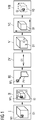
- Figure 1 shows a block diagram of the process flow of a preferred method according to the invention.
- Figures 2 to 4 see Figures 2 to 4 .
- a number of objects 01 is provided in the environment, each comprising a marking element M1.
- the marking element M1 here could comprise an individual identification code that is indicated with a pattern on the marking element M1.
- the marking element M1 is a visual marker with a defined dimension and is applied at a surface of the object 01.
- step II a visual image-dataset ID of the object O1 is recorded with a camera 2 such that an image of the marking element M1 i is visible in the image-dataset ID.
- a parameter value PV based on the marking element M1 here the size of the image of the marking element M1 i in the image-dataset ID, is determined. Also a beacon could be used as marking element M1 and its signal intensity could be measured as parameter value PV.
- the size of the image of the marking element M1 i depends on the distance between the object 01 and the camera 2.
- step IV the relative distance D1 between the object 01 and the camera 2 is calculated from the parameter value PV (the size of the image of the marking element M1 i ), e.g. by using the known size of the marking element M1 and the known distance of the image from the optic of the camera 2 or the focus of the optics of the camera 2.
- PV the size of the image of the marking element M1 i
- step V the dimensions a, b, c of the object 01 are calculated from at least a part of the image of the object 01 in the image-dataset ID and the calculated distance D1.
- step VI the relative position of the object 01 in the environment as seen by the camera 2 is calculated based on the calculated distance D1 and the position of the object 01 in the image-dataset ID.
- a virtual object VO is created within a virtual reality environment having the same distance and dimensions as the object 01 in the virtual reality environment, preferably providing an identification mark GI connected with the virtual object VO, particularly preferably wherein the identification mark GI of the virtual object VO corresponds to the pattern, i.e. the identification code, of the marking element M1 of the object O1.
- the identification mark GI of the virtual object VO corresponds to the pattern, i.e. the identification code, of the marking element M1 of the object O1.
- it is a virtual marker.
- a label could be applied to the virtual object VO.
- Figure 2 shows a preferred scheme for an acquisition of an image-dataset ID as well as a preferred device 1 and a preferred system 6.
- the preferred device 1 comprises:
- the device also comprises a virtual reality display 5, here a head-up display 5, to display virtual objects VO (see e.g. figure 1 ) for a user in a virtual reality environment.
- a virtual reality display here a head-up display 5
- virtual objects VO see e.g. figure 1
- the shown device 1 together with the virtual reality display 5 could serve as control unit according to the invention.
- the preferred system 6 comprises the device 1 and the number of objects O1, O2 each comprising a marking element M1, M2.
- Two objects O1, O2 are recorded with the camera 2.
- the method as described above and shown in figure 1 is applied, wherein the distances D1, D2 between the objects O1, O2 and the camera 2 are calculated as well as the dimensions a, b, c of the objects O1, O2 and the positions of the objects O1, O2 relative to a coordinate system X, Y, Z.
- This coordinate system X, Y, Z could be originate anywhere in the environment.
- the relative distance D3 between the objects O1, O2 is derived from these calculations.
- any point of an object O1, O2 can serve as origin for the calculation of a distance D1, D2.
- the marking elements M1, M2 are important features of the objects O1, O2, it is preferred to define them as origin.
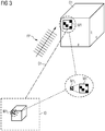
- Figure 3 shows another preferred scheme for an acquisition of an image-dataset ID.
- a high dynamic range image (HDR-image) with a series of focal points FP is recorded as image-dataset ID.
- the distance D1 and dimensions a, b, c of the object 01 can be calculated.
- the ratio of the sizes of the marking element M1 and the image of the marking element M1 i is used to calculate the dimensions a, b, c.
- the calculation is preferably achieved by slicing the area around a marking element M1 and/or the object 01, wherein the slices comprise images recorded with different focal points FP, wherein in each slice a higher amount of sharp spots are detected as plane/line.
- the depth of the recorded light field and/or the sharpness of the image is observed in the slices and image-dimensions of the image of the object 01 are calculated based on the depth of the recorded light field and/or the sharpness of the image.
- the distance D1 and/or dimension a, b, c of the object 01 is determined based on the image dimensions, preferably the dimensions of the marking element M1 and the known values of a focusing optics of the camera 2.
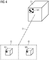
- Figure 4 shows another preferred scheme for an acquisition of an image-dataset ID.
- a stereo-image is recorded, wherein a relative distance D1 between an object 01 and the camera 2 is calculated using triangulation based on the (stereo-)image of the marking element M1 i .
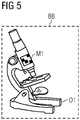
- Figure 5 shows an object 01 with a bounding box BB.
- This object 01 here a microscope
- This bounding box BB could be used.
- the bounding box BB could be designed by identifying the object 01 in the image-dataset ID and building a bounding box BB around the identified object.
Landscapes
- Engineering & Computer Science (AREA)
- Physics & Mathematics (AREA)
- Theoretical Computer Science (AREA)
- General Physics & Mathematics (AREA)
- Computer Vision & Pattern Recognition (AREA)
- General Engineering & Computer Science (AREA)
- Geometry (AREA)
- Data Mining & Analysis (AREA)
- Software Systems (AREA)
- Computer Hardware Design (AREA)
- Computer Graphics (AREA)
- Signal Processing (AREA)
- Computer Networks & Wireless Communication (AREA)
- Life Sciences & Earth Sciences (AREA)
- Evolutionary Biology (AREA)
- Evolutionary Computation (AREA)
- Bioinformatics & Computational Biology (AREA)
- Bioinformatics & Cheminformatics (AREA)
- Artificial Intelligence (AREA)
- Image Analysis (AREA)
- Length Measuring Devices By Optical Means (AREA)
- Processing Or Creating Images (AREA)
Claims (15)
- Procédé mis en œuvre par ordinateur pour déterminer les dimensions (a, b, c) et la distance (D1, D2) d'un nombre d'objets (O1, O2) dans leur environnement, comprenant les stades :- on prévoit un certain nombre d'objets (O1, O2), chacun comprenant un élément (M1, M2) de repérage, dans l'environnement,- on enregistre un ensemble (ID) de données d'image visuelles d'au moins l'un du nombre d'objets (01, O2) par un appareil (2) photographique, dans lequel, au cours de l'enregistrement d'un ensemble (ID) de données d'image visuelles, on enregistre une image avec des points de foyer différents,- on détermine une valeur (V) de paramètre à partir de l'image d'un élément (M1i, M2i) de repérage dans l'ensemble (ID) de données d'image, la valeur (PV) de paramètre étant d'une valeur dépendant de la distance (D1, D2) d'un objet du nombre d'objets (O1, O2), comprenant chacun un élément (M1, M2) de repérage, à l'appareil (2) photographique,- on calcule la distance relative entre l'objet (O1, O2) et l'appareil (2) photographique sur la base de cette valeur (PV) de paramètre,- on calcule des dimensions (a, b, c) de l'objet (O1, O2) à partir d'au moins une partie de l'image de l'objet (O1, O2) dans l'ensemble (ID) de données d'image et de la distance (D1, D2) calculée,dans lequel les dimensions (a,b,c ) de l'objet (O1, O2) sont déterminées en- découpant en tranches la région autour d'un élément (M1, M2) de repérage, les tranches comprenant des images enregistrées avec des points (FP) de foyer différents, et- observant la profondeur du champ lumineux enregistré et/ou la netteté de l'image dans les tranches et calculant des dimensions de l'image de l'objet (O1, O2) sur la base de la profondeur du champ lumineux enregistré et/ou de la netteté de l'image,- déterminant les dimensions (a, b, c) de l'objet (O1, O2) sur la base des dimensions de l'image de l'objet (O1, O2), des dimensions de l'élément (M1, M2) de repérage et des valeurs connues d'une optique de focalisation de l'appareil (2) photographique.
- Procédé suivant la revendication 1, dans lequel on calcule une position relative d'un objet (O1, O2) par rapport à l'appareil photographique sur la base de la distance (D1, D2) de l'objet et de la position de l'objet dans l'ensemble (ID) de données d'image, les dimensions (a, b, c) de l'objet (O1, O2) étant, de préférence, prises aussi en considération dans ce calcul.
- Procédé suivant l'une des revendications précédentes, dans lequel un certain nombre d'objets (O1, O2) comprennent un élément (M1, M2) de repérage, de préférence une étiquette Bluetooth de basse énergie, envoyant activement des signaux électromagnétiques ayant une forme de signal, qui dépend de la distance,
dans lequel l'élément (M1, M2) de repérage envoie et/ou expose de préférence un code individuel d'identification,
dans lequel on mesure le signal de l'élément de repérage par un capteur de l'appareil photographique ou par un capteur supplémentaire placé à l'endroit de l'appareil photographique. - Procédé suivant l'une des revendications précédentes, dans lequel on détermine la position relative de l'appareil (2) photographique par rapport à un objet (O1, O2) par une navigation d'intérieur Bluetooth de basse énergie, une localisation et une cartographie simultanées ou des capteurs inertiels.
- Procédé suivant l'une quelconque des revendications précédentes, dans lequel un élément (M1, M2) de repérage est un marqueur visuel d'une dimension définie et est appliqué à une surface d'un objet (O1, O2), la valeur (V) de paramètre déterminée étant l'image de l'élément (M1, M2) de repérage.
- Procédé suivant l'une des revendications précédentes, dans lequel, dans le cours de l'enregistrement d'un ensemble (ID ) de données d'image visuelles, on enregistre une image stéréo, une distance (D1, D2) relative, entre un objet (O1, O2) et l'appareil (2) photographique, étant calculée en utilisant une triangulisation reposant sur l'image stéréo de l'élément (M1i, M2i) de repérage.
- Procédé suivant l'une quelconque des revendications précédentes, dans lequel, au cours de l'enregistrement d'un ensemble (ID) de données d'image visuelles, on enregistre une image avec des points de foyer différents, la distance (D1, D2) étant déterminée en- découpant en tranches la région autour d'un élément (M1, M2) de repérage, les tranches comprenant des images à enregistrer avec des points (FP) de foyer différents, dans lequel, dans chaque tranche, on détecte une quantité assez grande de points nets sous la forme d'un plan/d'une ligne, et- observant la profondeur du champ lumineux enregistré et/ou la netteté de l'image dans les tranches et calculant des dimensions de l'image de l'objet (O1, O2) sur la base de la profondeur du champ lumineux enregistré et/ou de la netteté de l'image,- déterminant les dimensions (a, b, c) de l'objet (O1, O2) sur la base des dimensions de l'image de l'objet (O1, O2), des dimensions de l'élément (M1, M2) de repérage et des valeurs connues d'une optique de focalisation de l'appareil (2) photographique.
- Procédé suivant l'une quelconque des revendications précédentes, dans lequel on identifie un objet (O1, O2) dans l'ensemble (ID) de données d'image, dans lequel on forme de préférence une boîte (BB) de délimitation autour de l'objet (01, 02) identifié et on met la dimension d'un élément (M1, M2) de repérage en relation avec la boîte (BB) de délimitation autour de l'objet (O1, O2) pour déterminer les dimensions (a, b, c) de l'objet (O1, O2), en calculant, de préférence, combien de fois l'élément (M1, M2) de repérage s'ajuste dans la région de la boîte (BB) de délimitation.
- Procédé suivant l'une des revendications précédentes, comprenant le stade supplémentaire :- on crée un objet virtuel au sein d'une réalité virtuelle ayant la même distance et les même dimensions que l'objet (O1, O2), en prévoyant, de préférence, un repère d'identification relié à l'objet virtuel, dans lequel, d'une manière particulièrement préférée, le repère d'identification de l'objet virtuel correspond à un code d'identification d'un élément (M1, M2) de repérage de l'objet (O1, O2).
- Dispositif pour enregistrer un certain nombre d'objets (O1, O2) dans leur environnement, dans lequel un certain nombre d'objets (O1, O2) est pourvu d'un élément (M1, M2) de repérage, comprenant :- un appareil (2) photographique, conçu pour enregistrer un ensemble (ID) de données d'image visuelles, sous la forme d'une image avec des points de foyer différents, d'au moins l'un des objets (O1, O2),- un dispositif (3) de détermination, conçu pour déterminer une valeur de paramètre à partir d'une image d'un élément (M1i, M2i) de repérage dans le jeu (ID) de données d'image, la valeur (V) de paramètre dépendant de la distance (D1, D2) d'un objet du nombre d'objets (O1, O2), chacun comprenant un élément (M1, M2) de repérage, à l'appareil (2) photographique,- une unité (4) de calcul, conçue pourdans lequel les dimensions (a, b, c) de l'objet (O1, O2) sont déterminées ena) calculer la distance (D1, D2) relative entre l'objet (O1, O2) et l'appareil (2) photographique sur la base de cette valeur (V) de paramètre,b) calculer des dimensions (a, b, c) de l'objet (O1, O2) à partir d'au moins une partie de l'image de l'objet (O1, O2) dans le jeu (ID) de données d'image et de la distance (D1, D2) calculée,- découpant en tranches la région autour d'un élément (M1, M2) de repérage, les tranches comprenant des images enregistrées avec des points (FP) de foyer différents, et- observant la profondeur du champ lumineux enregistré et/ou la netteté de l'image dans les tranches et calculant des dimensions de l'image de l'objet (O1,O2) sur la base de la profondeur du champ lumineux enregistré et/ou de la netteté de l'image,- déterminant les dimensions (a, b, c) d'un objet (O1, O2) sur la base des dimensions de l'image de l'objet (O1, O2), des dimensions de l'élément (M1, M2) de repérage et des valeurs connues d'une optique de focalisation de l'appareil (2) photographique.
- Dispositif (1) suivant la revendication 10, comprenant un affichage (5) de réalité virtuelle, dans lequel le dispositif (1) comprend une unité de calcul de réalité virtuelle, conçue pour créer un objet virtuel ayant la même distance et les mêmes dimensions qu'un objet (O1, O2) de l'environnement et des objets virtuels d'affichage sur l'affichage (5) de réalité virtuelle.
- Système pour enregistrer un certain nombre d'objets (O1, O2) dans leur environnement, comprenant un dispositif (1) suivant la revendication 10 ou 11 et un certain nombre d'objets (O1, O2), de préférence des objets médicaux, d'une manière particulièrement préférée des dispositifs médicaux, comprenant chacun un élément (M1, M2) de repérage.
- Unité de commande d'un système de réalité virtuelle, comprenant un dispositif (1) suivant la revendication 10 ou 11.
- Produit de programme d'ordinateur, comprenant des instructions, qui, lorsque le programme est exécuté par un ordinateur, font que l'ordinateur effectue des stades du procédé suivant l'une quelconque des revendications 1 à 9.
- Support déchiffrable par ordinateur, comprenant des instructions, qui, lorsqu'elles sont exécutées par un ordinateur, font que l'ordinateur effectue les stades du procédé suivant l'une quelconque des revendications 1 à 9.
Priority Applications (3)
| Application Number | Priority Date | Filing Date | Title |
|---|---|---|---|
| EP19161318.1A EP3706076B1 (fr) | 2019-03-07 | 2019-03-07 | Procédé et dispositif pour déterminer les dimensions et la distance d'un certain nombre d'objets dans un environnement |
| US16/807,456 US11043037B2 (en) | 2019-03-07 | 2020-03-03 | Method and device to determine the dimensions and distance of a number of objects in an environment |
| CN202010150530.XA CN111667526B (zh) | 2019-03-07 | 2020-03-06 | 用于确定环境中的多个对象的尺寸和距离的方法和设备 |
Applications Claiming Priority (1)
| Application Number | Priority Date | Filing Date | Title |
|---|---|---|---|
| EP19161318.1A EP3706076B1 (fr) | 2019-03-07 | 2019-03-07 | Procédé et dispositif pour déterminer les dimensions et la distance d'un certain nombre d'objets dans un environnement |
Publications (2)
| Publication Number | Publication Date |
|---|---|
| EP3706076A1 EP3706076A1 (fr) | 2020-09-09 |
| EP3706076B1 true EP3706076B1 (fr) | 2021-02-24 |
Family
ID=65763264
Family Applications (1)
| Application Number | Title | Priority Date | Filing Date |
|---|---|---|---|
| EP19161318.1A Active EP3706076B1 (fr) | 2019-03-07 | 2019-03-07 | Procédé et dispositif pour déterminer les dimensions et la distance d'un certain nombre d'objets dans un environnement |
Country Status (3)
| Country | Link |
|---|---|
| US (1) | US11043037B2 (fr) |
| EP (1) | EP3706076B1 (fr) |
| CN (1) | CN111667526B (fr) |
Families Citing this family (10)
| Publication number | Priority date | Publication date | Assignee | Title |
|---|---|---|---|---|
| USD959447S1 (en) | 2019-12-20 | 2022-08-02 | Sap Se | Display system or portion thereof with a virtual three-dimensional animated graphical user interface |
| USD959476S1 (en) | 2019-12-20 | 2022-08-02 | Sap Se | Display system or portion thereof with a virtual three-dimensional animated graphical user interface |
| US11205296B2 (en) * | 2019-12-20 | 2021-12-21 | Sap Se | 3D data exploration using interactive cuboids |
| USD959477S1 (en) | 2019-12-20 | 2022-08-02 | Sap Se | Display system or portion thereof with a virtual three-dimensional animated graphical user interface |
| DE102020129792B4 (de) * | 2020-11-11 | 2023-03-09 | Volume Graphics Gmbh | Computerimplementiertes Verfahren zum Ermitteln eines Werts eines geometrischen Parameters |
| DE102021200676A1 (de) * | 2021-01-26 | 2022-07-28 | Robert Bosch Gmbh | Verfahren zu einem Erkennen und einem Darstellen von Oberflächenveränderungen an einem Objekt, Gerät und System aus mehreren Geräten zu einer Durchführung des Verfahrens |
| TW202237359A (zh) * | 2021-03-24 | 2022-10-01 | 日商發那科股份有限公司 | 三維測量系統 |
| KR102696176B1 (ko) * | 2022-01-28 | 2024-08-19 | 하드콘 주식회사 | 머신 좌표계와 영상 좌표계의 정합 방법 및 장치 |
| CN114565719B (zh) * | 2022-02-25 | 2025-07-08 | 上海微创医疗机器人(集团)股份有限公司 | 图像数据处理方法、图像平台、计算机设备和存储介质 |
| CN115375881A (zh) * | 2022-09-15 | 2022-11-22 | 未石互动科技股份有限公司 | 一种虚拟现实社交方法及系统 |
Family Cites Families (29)
| Publication number | Priority date | Publication date | Assignee | Title |
|---|---|---|---|---|
| US6396397B1 (en) * | 1993-02-26 | 2002-05-28 | Donnelly Corporation | Vehicle imaging system with stereo imaging |
| US20040106868A1 (en) * | 2002-09-16 | 2004-06-03 | Siau-Way Liew | Novel imaging markers in musculoskeletal disease |
| CN100538741C (zh) * | 2004-08-31 | 2009-09-09 | 美国西门子医疗解决公司 | 肺结节检测的候选项集产生 |
| US7863763B2 (en) * | 2005-11-22 | 2011-01-04 | Asml Netherlands B.V. | Binary sinusoidal sub-wavelength gratings as alignment marks |
| JP4424364B2 (ja) * | 2007-03-19 | 2010-03-03 | ソニー株式会社 | 画像処理装置、画像処理方法 |
| DE102007033486B4 (de) * | 2007-07-18 | 2010-06-17 | Metaio Gmbh | Verfahren und System zur Vermischung eines virtuellen Datenmodells mit einem von einer Kamera oder einer Darstellungsvorrichtung generierten Abbild |
| US20100321640A1 (en) * | 2009-06-22 | 2010-12-23 | Industrial Technology Research Institute | Projection display chip |
| EP2507615A2 (fr) * | 2009-12-22 | 2012-10-10 | New York University | Tri de particules colloïdales dans de multiples canaux avec des forces optiques : fractionnement optique prismatique |
| CN102192727A (zh) * | 2010-03-19 | 2011-09-21 | 阿尔卡特朗讯 | 移动手持设备和方法 |
| US9959595B2 (en) * | 2010-09-21 | 2018-05-01 | Mobileye Vision Technologies Ltd. | Dense structure from motion |
| EP2546806B1 (fr) * | 2011-07-11 | 2019-05-08 | Deutsche Telekom AG | Rendu à base d'image pour ar - permettant à l'utilisateur la génération d'un contenu en 3d |
| US9025252B2 (en) * | 2011-08-30 | 2015-05-05 | Microsoft Technology Licensing, Llc | Adjustment of a mixed reality display for inter-pupillary distance alignment |
| JP2014528347A (ja) * | 2011-10-10 | 2014-10-27 | トラクトゥス・コーポレーション | ハンドヘルドイメージングデバイスを用いて組織を完全に検査するための方法、装置、およびシステム |
| EP2608153A1 (fr) * | 2011-12-21 | 2013-06-26 | Harman Becker Automotive Systems GmbH | Procédé et système pour jouer une jeu avec réalité augmentée dans un véhicule à moteur |
| JP2015522959A (ja) * | 2012-04-26 | 2015-08-06 | ザ・トラスティーズ・オブ・コロンビア・ユニバーシティ・イン・ザ・シティ・オブ・ニューヨーク | 画像において対話式再合焦を提供するためのシステム、方法、及び媒体 |
| US9182812B2 (en) * | 2013-01-08 | 2015-11-10 | Ayotle | Virtual sensor systems and methods |
| CN104077746B (zh) * | 2013-03-29 | 2017-03-01 | 富士通株式会社 | 灰度图像处理方法及其装置 |
| CN103557859B (zh) * | 2013-10-10 | 2015-12-23 | 北京智谷睿拓技术服务有限公司 | 图像采集定位方法及图像采集定位系统 |
| JP6264834B2 (ja) * | 2013-10-24 | 2018-01-24 | 富士通株式会社 | ガイド方法、情報処理装置およびガイドプログラム |
| CN103591943A (zh) * | 2013-11-17 | 2014-02-19 | 罗建刚 | 图像指引放线的方法 |
| US20160125638A1 (en) * | 2014-11-04 | 2016-05-05 | Dassault Systemes | Automated Texturing Mapping and Animation from Images |
| CN104572967B (zh) * | 2014-12-30 | 2018-01-19 | 北京奇虎科技有限公司 | 一种在页面绘制图形的方法和装置 |
| CN106327449B (zh) * | 2016-09-12 | 2019-05-03 | 厦门美图之家科技有限公司 | 一种图像修复方法、装置和计算设备 |
| US10366263B2 (en) * | 2016-12-30 | 2019-07-30 | Accenture Global Solutions Limited | Object detection for video camera self-calibration |
| CA3009798A1 (fr) * | 2017-07-12 | 2019-01-12 | General Electric Company | Superposition graphique servant a mesurer les dimensions des caracteristiques au moyen d'un appareil d'inspection video |
| DE102017215074A1 (de) * | 2017-08-29 | 2019-02-28 | Siemens Healthcare Gmbh | Verfahren und Auswahleinheit zum Auswählen eines virtuellen Objekts oder eines Bildparameterwerts |
| WO2019097456A1 (fr) * | 2017-11-17 | 2019-05-23 | C 3 Limited | Système de mesure d'objet |
| CN108765338A (zh) * | 2018-05-28 | 2018-11-06 | 西华大学 | 基于卷积自编码卷积神经网络的空间目标图像复原方法 |
| US11010919B2 (en) * | 2018-09-20 | 2021-05-18 | Ford Global Technologies, Llc | Object locator with fiducial marker |
-
2019
- 2019-03-07 EP EP19161318.1A patent/EP3706076B1/fr active Active
-
2020
- 2020-03-03 US US16/807,456 patent/US11043037B2/en active Active
- 2020-03-06 CN CN202010150530.XA patent/CN111667526B/zh active Active
Non-Patent Citations (1)
| Title |
|---|
| None * |
Also Published As
| Publication number | Publication date |
|---|---|
| EP3706076A1 (fr) | 2020-09-09 |
| US11043037B2 (en) | 2021-06-22 |
| US20200286291A1 (en) | 2020-09-10 |
| CN111667526A (zh) | 2020-09-15 |
| CN111667526B (zh) | 2023-07-28 |
Similar Documents
| Publication | Publication Date | Title |
|---|---|---|
| EP3706076B1 (fr) | Procédé et dispositif pour déterminer les dimensions et la distance d'un certain nombre d'objets dans un environnement | |
| US9448758B2 (en) | Projecting airplane location specific maintenance history using optical reference points | |
| Wasenmüller et al. | Comparison of kinect v1 and v2 depth images in terms of accuracy and precision | |
| CN110009682B (zh) | 一种基于单目视觉的目标识别定位方法 | |
| TWI496108B (zh) | AR image processing apparatus and method | |
| US20170132806A1 (en) | System and method for augmented reality and virtual reality applications | |
| US8086026B2 (en) | Method and system for the determination of object positions in a volume | |
| CN107014378A (zh) | 一种视线跟踪瞄准操控系统及方法 | |
| RU2720076C1 (ru) | Способ оценивания по реперным точкам угловых и пространственных координат объекта в оптико-электронной системе позиционирования | |
| JP2009538487A (ja) | 拡張現実を使用して装置の保守命令および動作命令を表示するシステムおよび方法 | |
| US11259000B2 (en) | Spatiotemporal calibration of RGB-D and displacement sensors | |
| CN113884081B (zh) | 测定定位点三维坐标的方法及设备 | |
| KR20240056516A (ko) | 카메라 교정을 위한 카메라 모델을 생성하는 방법 및 시스템 | |
| CN107478172A (zh) | 基于双目视觉的激光三维曲线轮廓定位投影方法 | |
| CN108257177A (zh) | 基于空间标识的定位系统与方法 | |
| Sun et al. | High-accuracy three-dimensional measurement based on multi-directional cooperative target with weighted SfM algorithm | |
| Thabit et al. | Evaluation of marker tracking using mono and stereo vision in Microsoft HoloLens for surgical navigation | |
| Feng et al. | Unmanned aerial vehicle-aided stereo camera calibration for outdoor applications | |
| CN107014293A (zh) | 一种相机扫描成像的摄影测量方法 | |
| Knyaz et al. | Robust object tracking techniques for vision-based 3D motion analysis applications | |
| CN208314856U (zh) | 一种用于单目机载目标检测的系统 | |
| JP7640427B2 (ja) | 注視位置分析システム及び注視位置分析方法 | |
| Xu et al. | Multi-target indoor tracking and recognition system with infrared markers for virtual reality | |
| Rezzoug et al. | A Vision Based Optical Measurement Technique With Augmented Reality Concepts | |
| Yuan et al. | A vision-based method for autonomous landing of a rotor-craft unmanned aerial vehicle |
Legal Events
| Date | Code | Title | Description |
|---|---|---|---|
| STAA | Information on the status of an ep patent application or granted ep patent |
Free format text: STATUS: EXAMINATION IS IN PROGRESS |
|
| PUAI | Public reference made under article 153(3) epc to a published international application that has entered the european phase |
Free format text: ORIGINAL CODE: 0009012 |
|
| 17P | Request for examination filed |
Effective date: 20191219 |
|
| AK | Designated contracting states |
Kind code of ref document: A1 Designated state(s): AL AT BE BG CH CY CZ DE DK EE ES FI FR GB GR HR HU IE IS IT LI LT LU LV MC MK MT NL NO PL PT RO RS SE SI SK SM TR |
|
| AX | Request for extension of the european patent |
Extension state: BA ME |
|
| GRAP | Despatch of communication of intention to grant a patent |
Free format text: ORIGINAL CODE: EPIDOSNIGR1 |
|
| STAA | Information on the status of an ep patent application or granted ep patent |
Free format text: STATUS: GRANT OF PATENT IS INTENDED |
|
| INTG | Intention to grant announced |
Effective date: 20200924 |
|
| GRAS | Grant fee paid |
Free format text: ORIGINAL CODE: EPIDOSNIGR3 |
|
| GRAA | (expected) grant |
Free format text: ORIGINAL CODE: 0009210 |
|
| STAA | Information on the status of an ep patent application or granted ep patent |
Free format text: STATUS: THE PATENT HAS BEEN GRANTED |
|
| AK | Designated contracting states |
Kind code of ref document: B1 Designated state(s): AL AT BE BG CH CY CZ DE DK EE ES FI FR GB GR HR HU IE IS IT LI LT LU LV MC MK MT NL NO PL PT RO RS SE SI SK SM TR |
|
| REG | Reference to a national code |
Ref country code: CH Ref legal event code: EP |
|
| REG | Reference to a national code |
Ref country code: DE Ref legal event code: R096 Ref document number: 602019002649 Country of ref document: DE |
|
| REG | Reference to a national code |
Ref country code: AT Ref legal event code: REF Ref document number: 1365441 Country of ref document: AT Kind code of ref document: T Effective date: 20210315 |
|
| REG | Reference to a national code |
Ref country code: IE Ref legal event code: FG4D |
|
| REG | Reference to a national code |
Ref country code: LT Ref legal event code: MG9D |
|
| REG | Reference to a national code |
Ref country code: NL Ref legal event code: MP Effective date: 20210224 |
|
| PG25 | Lapsed in a contracting state [announced via postgrant information from national office to epo] |
Ref country code: BG Free format text: LAPSE BECAUSE OF FAILURE TO SUBMIT A TRANSLATION OF THE DESCRIPTION OR TO PAY THE FEE WITHIN THE PRESCRIBED TIME-LIMIT Effective date: 20210524 Ref country code: GR Free format text: LAPSE BECAUSE OF FAILURE TO SUBMIT A TRANSLATION OF THE DESCRIPTION OR TO PAY THE FEE WITHIN THE PRESCRIBED TIME-LIMIT Effective date: 20210525 Ref country code: FI Free format text: LAPSE BECAUSE OF FAILURE TO SUBMIT A TRANSLATION OF THE DESCRIPTION OR TO PAY THE FEE WITHIN THE PRESCRIBED TIME-LIMIT Effective date: 20210224 Ref country code: HR Free format text: LAPSE BECAUSE OF FAILURE TO SUBMIT A TRANSLATION OF THE DESCRIPTION OR TO PAY THE FEE WITHIN THE PRESCRIBED TIME-LIMIT Effective date: 20210224 Ref country code: LT Free format text: LAPSE BECAUSE OF FAILURE TO SUBMIT A TRANSLATION OF THE DESCRIPTION OR TO PAY THE FEE WITHIN THE PRESCRIBED TIME-LIMIT Effective date: 20210224 Ref country code: PT Free format text: LAPSE BECAUSE OF FAILURE TO SUBMIT A TRANSLATION OF THE DESCRIPTION OR TO PAY THE FEE WITHIN THE PRESCRIBED TIME-LIMIT Effective date: 20210624 Ref country code: NO Free format text: LAPSE BECAUSE OF FAILURE TO SUBMIT A TRANSLATION OF THE DESCRIPTION OR TO PAY THE FEE WITHIN THE PRESCRIBED TIME-LIMIT Effective date: 20210524 |
|
| REG | Reference to a national code |
Ref country code: AT Ref legal event code: MK05 Ref document number: 1365441 Country of ref document: AT Kind code of ref document: T Effective date: 20210224 |
|
| PG25 | Lapsed in a contracting state [announced via postgrant information from national office to epo] |
Ref country code: SE Free format text: LAPSE BECAUSE OF FAILURE TO SUBMIT A TRANSLATION OF THE DESCRIPTION OR TO PAY THE FEE WITHIN THE PRESCRIBED TIME-LIMIT Effective date: 20210224 Ref country code: PL Free format text: LAPSE BECAUSE OF FAILURE TO SUBMIT A TRANSLATION OF THE DESCRIPTION OR TO PAY THE FEE WITHIN THE PRESCRIBED TIME-LIMIT Effective date: 20210224 Ref country code: NL Free format text: LAPSE BECAUSE OF FAILURE TO SUBMIT A TRANSLATION OF THE DESCRIPTION OR TO PAY THE FEE WITHIN THE PRESCRIBED TIME-LIMIT Effective date: 20210224 Ref country code: LV Free format text: LAPSE BECAUSE OF FAILURE TO SUBMIT A TRANSLATION OF THE DESCRIPTION OR TO PAY THE FEE WITHIN THE PRESCRIBED TIME-LIMIT Effective date: 20210224 Ref country code: RS Free format text: LAPSE BECAUSE OF FAILURE TO SUBMIT A TRANSLATION OF THE DESCRIPTION OR TO PAY THE FEE WITHIN THE PRESCRIBED TIME-LIMIT Effective date: 20210224 |
|
| PG25 | Lapsed in a contracting state [announced via postgrant information from national office to epo] |
Ref country code: IS Free format text: LAPSE BECAUSE OF FAILURE TO SUBMIT A TRANSLATION OF THE DESCRIPTION OR TO PAY THE FEE WITHIN THE PRESCRIBED TIME-LIMIT Effective date: 20210624 |
|
| PG25 | Lapsed in a contracting state [announced via postgrant information from national office to epo] |
Ref country code: SM Free format text: LAPSE BECAUSE OF FAILURE TO SUBMIT A TRANSLATION OF THE DESCRIPTION OR TO PAY THE FEE WITHIN THE PRESCRIBED TIME-LIMIT Effective date: 20210224 Ref country code: AT Free format text: LAPSE BECAUSE OF FAILURE TO SUBMIT A TRANSLATION OF THE DESCRIPTION OR TO PAY THE FEE WITHIN THE PRESCRIBED TIME-LIMIT Effective date: 20210224 Ref country code: EE Free format text: LAPSE BECAUSE OF FAILURE TO SUBMIT A TRANSLATION OF THE DESCRIPTION OR TO PAY THE FEE WITHIN THE PRESCRIBED TIME-LIMIT Effective date: 20210224 Ref country code: CZ Free format text: LAPSE BECAUSE OF FAILURE TO SUBMIT A TRANSLATION OF THE DESCRIPTION OR TO PAY THE FEE WITHIN THE PRESCRIBED TIME-LIMIT Effective date: 20210224 |
|
| REG | Reference to a national code |
Ref country code: DE Ref legal event code: R097 Ref document number: 602019002649 Country of ref document: DE |
|
| PG25 | Lapsed in a contracting state [announced via postgrant information from national office to epo] |
Ref country code: DK Free format text: LAPSE BECAUSE OF FAILURE TO SUBMIT A TRANSLATION OF THE DESCRIPTION OR TO PAY THE FEE WITHIN THE PRESCRIBED TIME-LIMIT Effective date: 20210224 Ref country code: SK Free format text: LAPSE BECAUSE OF FAILURE TO SUBMIT A TRANSLATION OF THE DESCRIPTION OR TO PAY THE FEE WITHIN THE PRESCRIBED TIME-LIMIT Effective date: 20210224 Ref country code: RO Free format text: LAPSE BECAUSE OF FAILURE TO SUBMIT A TRANSLATION OF THE DESCRIPTION OR TO PAY THE FEE WITHIN THE PRESCRIBED TIME-LIMIT Effective date: 20210224 Ref country code: MC Free format text: LAPSE BECAUSE OF FAILURE TO SUBMIT A TRANSLATION OF THE DESCRIPTION OR TO PAY THE FEE WITHIN THE PRESCRIBED TIME-LIMIT Effective date: 20210224 |
|
| REG | Reference to a national code |
Ref country code: BE Ref legal event code: MM Effective date: 20210331 |
|
| PLBE | No opposition filed within time limit |
Free format text: ORIGINAL CODE: 0009261 |
|
| STAA | Information on the status of an ep patent application or granted ep patent |
Free format text: STATUS: NO OPPOSITION FILED WITHIN TIME LIMIT |
|
| PG25 | Lapsed in a contracting state [announced via postgrant information from national office to epo] |
Ref country code: LU Free format text: LAPSE BECAUSE OF NON-PAYMENT OF DUE FEES Effective date: 20210307 Ref country code: IE Free format text: LAPSE BECAUSE OF NON-PAYMENT OF DUE FEES Effective date: 20210307 Ref country code: AL Free format text: LAPSE BECAUSE OF FAILURE TO SUBMIT A TRANSLATION OF THE DESCRIPTION OR TO PAY THE FEE WITHIN THE PRESCRIBED TIME-LIMIT Effective date: 20210224 Ref country code: ES Free format text: LAPSE BECAUSE OF FAILURE TO SUBMIT A TRANSLATION OF THE DESCRIPTION OR TO PAY THE FEE WITHIN THE PRESCRIBED TIME-LIMIT Effective date: 20210224 |
|
| 26N | No opposition filed |
Effective date: 20211125 |
|
| PG25 | Lapsed in a contracting state [announced via postgrant information from national office to epo] |
Ref country code: IT Free format text: LAPSE BECAUSE OF FAILURE TO SUBMIT A TRANSLATION OF THE DESCRIPTION OR TO PAY THE FEE WITHIN THE PRESCRIBED TIME-LIMIT Effective date: 20210224 |
|
| PG25 | Lapsed in a contracting state [announced via postgrant information from national office to epo] |
Ref country code: IS Free format text: LAPSE BECAUSE OF FAILURE TO SUBMIT A TRANSLATION OF THE DESCRIPTION OR TO PAY THE FEE WITHIN THE PRESCRIBED TIME-LIMIT Effective date: 20210624 |
|
| PG25 | Lapsed in a contracting state [announced via postgrant information from national office to epo] |
Ref country code: BE Free format text: LAPSE BECAUSE OF NON-PAYMENT OF DUE FEES Effective date: 20210331 |
|
| REG | Reference to a national code |
Ref country code: CH Ref legal event code: PL |
|
| PG25 | Lapsed in a contracting state [announced via postgrant information from national office to epo] |
Ref country code: LI Free format text: LAPSE BECAUSE OF NON-PAYMENT OF DUE FEES Effective date: 20220331 Ref country code: CH Free format text: LAPSE BECAUSE OF NON-PAYMENT OF DUE FEES Effective date: 20220331 |
|
| PG25 | Lapsed in a contracting state [announced via postgrant information from national office to epo] |
Ref country code: CY Free format text: LAPSE BECAUSE OF FAILURE TO SUBMIT A TRANSLATION OF THE DESCRIPTION OR TO PAY THE FEE WITHIN THE PRESCRIBED TIME-LIMIT Effective date: 20210224 |
|
| PG25 | Lapsed in a contracting state [announced via postgrant information from national office to epo] |
Ref country code: SI Free format text: LAPSE BECAUSE OF FAILURE TO SUBMIT A TRANSLATION OF THE DESCRIPTION OR TO PAY THE FEE WITHIN THE PRESCRIBED TIME-LIMIT Effective date: 20210224 Ref country code: HU Free format text: LAPSE BECAUSE OF FAILURE TO SUBMIT A TRANSLATION OF THE DESCRIPTION OR TO PAY THE FEE WITHIN THE PRESCRIBED TIME-LIMIT; INVALID AB INITIO Effective date: 20190307 |
|
| REG | Reference to a national code |
Ref country code: DE Ref legal event code: R081 Ref document number: 602019002649 Country of ref document: DE Owner name: SIEMENS HEALTHINEERS AG, DE Free format text: FORMER OWNER: SIEMENS HEALTHCARE GMBH, MUENCHEN, DE |
|
| PG25 | Lapsed in a contracting state [announced via postgrant information from national office to epo] |
Ref country code: MK Free format text: LAPSE BECAUSE OF FAILURE TO SUBMIT A TRANSLATION OF THE DESCRIPTION OR TO PAY THE FEE WITHIN THE PRESCRIBED TIME-LIMIT Effective date: 20210224 |
|
| PG25 | Lapsed in a contracting state [announced via postgrant information from national office to epo] |
Ref country code: MT Free format text: LAPSE BECAUSE OF FAILURE TO SUBMIT A TRANSLATION OF THE DESCRIPTION OR TO PAY THE FEE WITHIN THE PRESCRIBED TIME-LIMIT Effective date: 20210224 |
|
| PGFP | Annual fee paid to national office [announced via postgrant information from national office to epo] |
Ref country code: DE Payment date: 20250520 Year of fee payment: 7 |
|
| PGFP | Annual fee paid to national office [announced via postgrant information from national office to epo] |
Ref country code: GB Payment date: 20250403 Year of fee payment: 7 |
|
| PG25 | Lapsed in a contracting state [announced via postgrant information from national office to epo] |
Ref country code: TR Free format text: LAPSE BECAUSE OF FAILURE TO SUBMIT A TRANSLATION OF THE DESCRIPTION OR TO PAY THE FEE WITHIN THE PRESCRIBED TIME-LIMIT Effective date: 20210224 |
|
| PGFP | Annual fee paid to national office [announced via postgrant information from national office to epo] |
Ref country code: FR Payment date: 20260316 Year of fee payment: 8 |