EP3706284A1 - Bloc-batterie - Google Patents
Bloc-batterie Download PDFInfo
- Publication number
- EP3706284A1 EP3706284A1 EP20161605.9A EP20161605A EP3706284A1 EP 3706284 A1 EP3706284 A1 EP 3706284A1 EP 20161605 A EP20161605 A EP 20161605A EP 3706284 A1 EP3706284 A1 EP 3706284A1
- Authority
- EP
- European Patent Office
- Prior art keywords
- battery cells
- terminal
- battery pack
- output interface
- power output
- Prior art date
- Legal status (The legal status is an assumption and is not a legal conclusion. Google has not performed a legal analysis and makes no representation as to the accuracy of the status listed.)
- Granted
Links
Images


Classifications
-
- H—ELECTRICITY
- H02—GENERATION; CONVERSION OR DISTRIBUTION OF ELECTRIC POWER
- H02J—ELECTRIC POWER NETWORKS; CIRCUIT ARRANGEMENTS OR SYSTEMS FOR SUPPLYING OR DISTRIBUTING ELECTRIC POWER; SYSTEMS FOR STORING ELECTRIC ENERGY
- H02J7/00—Circuit arrangements for charging or discharging batteries or for supplying loads from batteries
- H02J7/50—Circuit arrangements for charging or discharging batteries or for supplying loads from batteries acting upon multiple batteries simultaneously or sequentially
- H02J7/575—Parallel/serial switching of connection of batteries to charge or load circuit
-
- H—ELECTRICITY
- H01—ELECTRIC ELEMENTS
- H01M—PROCESSES OR MEANS, e.g. BATTERIES, FOR THE DIRECT CONVERSION OF CHEMICAL ENERGY INTO ELECTRICAL ENERGY
- H01M50/00—Constructional details or processes of manufacture of the non-active parts of electrochemical cells other than fuel cells, e.g. hybrid cells
- H01M50/20—Mountings; Secondary casings or frames; Racks, modules or packs; Suspension devices; Shock absorbers; Transport or carrying devices; Holders
- H01M50/204—Racks, modules or packs for multiple batteries or multiple cells
- H01M50/207—Racks, modules or packs for multiple batteries or multiple cells characterised by their shape
- H01M50/213—Racks, modules or packs for multiple batteries or multiple cells characterised by their shape adapted for cells having curved cross-section, e.g. round or elliptic
-
- H—ELECTRICITY
- H01—ELECTRIC ELEMENTS
- H01M—PROCESSES OR MEANS, e.g. BATTERIES, FOR THE DIRECT CONVERSION OF CHEMICAL ENERGY INTO ELECTRICAL ENERGY
- H01M10/00—Secondary cells; Manufacture thereof
- H01M10/42—Methods or arrangements for servicing or maintenance of secondary cells or secondary half-cells
- H01M10/4207—Methods or arrangements for servicing or maintenance of secondary cells or secondary half-cells for several batteries or cells simultaneously or sequentially
-
- H—ELECTRICITY
- H01—ELECTRIC ELEMENTS
- H01M—PROCESSES OR MEANS, e.g. BATTERIES, FOR THE DIRECT CONVERSION OF CHEMICAL ENERGY INTO ELECTRICAL ENERGY
- H01M10/00—Secondary cells; Manufacture thereof
- H01M10/42—Methods or arrangements for servicing or maintenance of secondary cells or secondary half-cells
- H01M10/425—Structural combination with electronic components, e.g. electronic circuits integrated to the outside of the casing
-
- H—ELECTRICITY
- H01—ELECTRIC ELEMENTS
- H01M—PROCESSES OR MEANS, e.g. BATTERIES, FOR THE DIRECT CONVERSION OF CHEMICAL ENERGY INTO ELECTRICAL ENERGY
- H01M50/00—Constructional details or processes of manufacture of the non-active parts of electrochemical cells other than fuel cells, e.g. hybrid cells
- H01M50/20—Mountings; Secondary casings or frames; Racks, modules or packs; Suspension devices; Shock absorbers; Transport or carrying devices; Holders
- H01M50/204—Racks, modules or packs for multiple batteries or multiple cells
-
- H—ELECTRICITY
- H01—ELECTRIC ELEMENTS
- H01M—PROCESSES OR MEANS, e.g. BATTERIES, FOR THE DIRECT CONVERSION OF CHEMICAL ENERGY INTO ELECTRICAL ENERGY
- H01M50/00—Constructional details or processes of manufacture of the non-active parts of electrochemical cells other than fuel cells, e.g. hybrid cells
- H01M50/20—Mountings; Secondary casings or frames; Racks, modules or packs; Suspension devices; Shock absorbers; Transport or carrying devices; Holders
- H01M50/247—Mountings; Secondary casings or frames; Racks, modules or packs; Suspension devices; Shock absorbers; Transport or carrying devices; Holders specially adapted for portable devices, e.g. mobile phones, computers, hand tools or pacemakers
-
- H—ELECTRICITY
- H01—ELECTRIC ELEMENTS
- H01M—PROCESSES OR MEANS, e.g. BATTERIES, FOR THE DIRECT CONVERSION OF CHEMICAL ENERGY INTO ELECTRICAL ENERGY
- H01M50/00—Constructional details or processes of manufacture of the non-active parts of electrochemical cells other than fuel cells, e.g. hybrid cells
- H01M50/20—Mountings; Secondary casings or frames; Racks, modules or packs; Suspension devices; Shock absorbers; Transport or carrying devices; Holders
- H01M50/271—Lids or covers for the racks or secondary casings
-
- H—ELECTRICITY
- H01—ELECTRIC ELEMENTS
- H01M—PROCESSES OR MEANS, e.g. BATTERIES, FOR THE DIRECT CONVERSION OF CHEMICAL ENERGY INTO ELECTRICAL ENERGY
- H01M50/00—Constructional details or processes of manufacture of the non-active parts of electrochemical cells other than fuel cells, e.g. hybrid cells
- H01M50/20—Mountings; Secondary casings or frames; Racks, modules or packs; Suspension devices; Shock absorbers; Transport or carrying devices; Holders
- H01M50/284—Mountings; Secondary casings or frames; Racks, modules or packs; Suspension devices; Shock absorbers; Transport or carrying devices; Holders with incorporated circuit boards, e.g. printed circuit boards [PCB]
-
- H—ELECTRICITY
- H01—ELECTRIC ELEMENTS
- H01M—PROCESSES OR MEANS, e.g. BATTERIES, FOR THE DIRECT CONVERSION OF CHEMICAL ENERGY INTO ELECTRICAL ENERGY
- H01M50/00—Constructional details or processes of manufacture of the non-active parts of electrochemical cells other than fuel cells, e.g. hybrid cells
- H01M50/20—Mountings; Secondary casings or frames; Racks, modules or packs; Suspension devices; Shock absorbers; Transport or carrying devices; Holders
- H01M50/296—Mountings; Secondary casings or frames; Racks, modules or packs; Suspension devices; Shock absorbers; Transport or carrying devices; Holders characterised by terminals of battery packs
-
- H—ELECTRICITY
- H02—GENERATION; CONVERSION OR DISTRIBUTION OF ELECTRIC POWER
- H02J—ELECTRIC POWER NETWORKS; CIRCUIT ARRANGEMENTS OR SYSTEMS FOR SUPPLYING OR DISTRIBUTING ELECTRIC POWER; SYSTEMS FOR STORING ELECTRIC ENERGY
- H02J7/00—Circuit arrangements for charging or discharging batteries or for supplying loads from batteries
- H02J7/855—Circuit arrangements for charging or discharging batteries or for supplying loads from batteries with circuits adapted for supplying loads from the battery
-
- H—ELECTRICITY
- H01—ELECTRIC ELEMENTS
- H01M—PROCESSES OR MEANS, e.g. BATTERIES, FOR THE DIRECT CONVERSION OF CHEMICAL ENERGY INTO ELECTRICAL ENERGY
- H01M10/00—Secondary cells; Manufacture thereof
- H01M10/42—Methods or arrangements for servicing or maintenance of secondary cells or secondary half-cells
- H01M10/425—Structural combination with electronic components, e.g. electronic circuits integrated to the outside of the casing
- H01M2010/4271—Battery management systems including electronic circuits, e.g. control of current or voltage to keep battery in healthy state, cell balancing
-
- H—ELECTRICITY
- H01—ELECTRIC ELEMENTS
- H01M—PROCESSES OR MEANS, e.g. BATTERIES, FOR THE DIRECT CONVERSION OF CHEMICAL ENERGY INTO ELECTRICAL ENERGY
- H01M2220/00—Batteries for particular applications
- H01M2220/30—Batteries in portable systems, e.g. mobile phone, laptop
-
- H—ELECTRICITY
- H01—ELECTRIC ELEMENTS
- H01R—ELECTRICALLY-CONDUCTIVE CONNECTIONS; STRUCTURAL ASSOCIATIONS OF A PLURALITY OF MUTUALLY-INSULATED ELECTRICAL CONNECTING ELEMENTS; COUPLING DEVICES; CURRENT COLLECTORS
- H01R13/00—Details of coupling devices of the kinds covered by groups H01R12/70 or H01R24/00 - H01R33/00
- H01R13/44—Means for preventing access to live contacts
- H01R13/447—Shutter or cover plate
- H01R13/453—Shutter or cover plate opened by engagement of counterpart
- H01R13/4534—Laterally sliding shutter
-
- H—ELECTRICITY
- H01—ELECTRIC ELEMENTS
- H01R—ELECTRICALLY-CONDUCTIVE CONNECTIONS; STRUCTURAL ASSOCIATIONS OF A PLURALITY OF MUTUALLY-INSULATED ELECTRICAL CONNECTING ELEMENTS; COUPLING DEVICES; CURRENT COLLECTORS
- H01R13/00—Details of coupling devices of the kinds covered by groups H01R12/70 or H01R24/00 - H01R33/00
- H01R13/66—Structural association with built-in electrical component
- H01R13/70—Structural association with built-in electrical component with built-in switch
- H01R13/701—Structural association with built-in electrical component with built-in switch the switch being actuated by an accessory, e.g. cover, locking member
-
- H—ELECTRICITY
- H02—GENERATION; CONVERSION OR DISTRIBUTION OF ELECTRIC POWER
- H02J—ELECTRIC POWER NETWORKS; CIRCUIT ARRANGEMENTS OR SYSTEMS FOR SUPPLYING OR DISTRIBUTING ELECTRIC POWER; SYSTEMS FOR STORING ELECTRIC ENERGY
- H02J7/00—Circuit arrangements for charging or discharging batteries or for supplying loads from batteries
- H02J7/70—Circuit arrangements for charging or discharging batteries or for supplying loads from batteries characterised by the mechanical construction
-
- Y—GENERAL TAGGING OF NEW TECHNOLOGICAL DEVELOPMENTS; GENERAL TAGGING OF CROSS-SECTIONAL TECHNOLOGIES SPANNING OVER SEVERAL SECTIONS OF THE IPC; TECHNICAL SUBJECTS COVERED BY FORMER USPC CROSS-REFERENCE ART COLLECTIONS [XRACs] AND DIGESTS
- Y02—TECHNOLOGIES OR APPLICATIONS FOR MITIGATION OR ADAPTATION AGAINST CLIMATE CHANGE
- Y02E—REDUCTION OF GREENHOUSE GAS [GHG] EMISSIONS, RELATED TO ENERGY GENERATION, TRANSMISSION OR DISTRIBUTION
- Y02E60/00—Enabling technologies; Technologies with a potential or indirect contribution to GHG emissions mitigation
- Y02E60/10—Energy storage using batteries
-
- Y—GENERAL TAGGING OF NEW TECHNOLOGICAL DEVELOPMENTS; GENERAL TAGGING OF CROSS-SECTIONAL TECHNOLOGIES SPANNING OVER SEVERAL SECTIONS OF THE IPC; TECHNICAL SUBJECTS COVERED BY FORMER USPC CROSS-REFERENCE ART COLLECTIONS [XRACs] AND DIGESTS
- Y02—TECHNOLOGIES OR APPLICATIONS FOR MITIGATION OR ADAPTATION AGAINST CLIMATE CHANGE
- Y02T—CLIMATE CHANGE MITIGATION TECHNOLOGIES RELATED TO TRANSPORTATION
- Y02T10/00—Road transport of goods or passengers
- Y02T10/60—Other road transportation technologies with climate change mitigation effect
- Y02T10/70—Energy storage systems for electromobility, e.g. batteries
Definitions
- the present invention generally relates to a battery pack, and more particularly to a battery pack which can output at three different voltages.
- the output of multiple voltages on battery packs has become a new trend in the electrical tool industry.
- the present dual-voltage battery packs include two sets of batteries that can output two sets of voltages. It is necessary to add a charging port (usually a USB interface) to recharge the phones and other devices. When using the USB interface, the USB circuit cannot take power from one set of battery alone, because this will cause the battery voltage on both sides to be unbalanced and there is a risk of use.
- the aim of the present invention is to provide a safe and reliable battery pack which can supply power for mobile phones or other external devices.
- a battery pack comprises a case, a first set of battery cells and a second set of battery cells received in the case, a circuit board, a main power output interface, a switch provided between the first set of battery cells and the second set of battery cells, and an extended power output interface.
- the first set of battery cells and the second set of battery cells can be connected in series or in parallel, and output two kinds of working voltages through the main power output interface.
- the battery pack can output a third voltage for an external device through the extended power output interface when the first set of battery cells is connected to the second set of battery cells in series through the switch.
- a battery pack comprises a case, a first set of battery cells and a second set of battery cells received in the case, a main power output interface connecting to the first set of battery cells and the second set of battery cells via a first circuit, and an extended power output interface connecting to the first set of battery cells and the second set of battery cells via a second circuit.
- the main power output interface outputs two kinds of working voltages for power tools through connecting the first and second sets of battery cells in series or in parallel.
- the second circuit comprises a switch connecting the first set of battery cells and the second set of battery cells in series, and the extended power output interface outputs a third voltage for an external device when the first and second sets of battery cells are connected in series through the switch. The third voltage is different from that for power tools.
- a battery pack 100 includes a case 1, a battery set 2 received in the case 1, a circuit board 3 electrically connected to the battery set 2, a main power output interface 6 electrically connected to the circuit board 3, and an extended power output interface 4.
- the case 1 has an upper case 11 and a lower case 12.
- the battery set 2 includes a first set of battery cells 21 and a second set of battery cells 22.
- a switch 5 located between the first set of battery cells 21 and the second set of battery cells 22 is used for connecting or disconnecting the first set of battery cells 21 to the second set of battery cells 22.
- the first set of battery cells 21 and the second set of battery cells 22 can be connected in series or in parallel, and output two kinds of working voltages through the main power output interface 6 in order to supply electricity for power tools with different requirements.
- Two kinds of working voltages include one low voltage and one high voltage.
- the first set of battery cells 21 and the second set of battery cells 22 can be connected in series and can supply power to a mobile phone or other external devices through the extended power output interface 4.
- the mobile phone or other external devices have working voltages different from two kinds of voltages supplied to power tools.
- a circuit of the battery pack 100 for supplying power to the external device 4 includes the first set of battery cells 21, the second set of battery cells 22, the switch 5, a conversion circuit 7, and the extended power output interface 4.
- the switch 5 is arranged between two electrodes having different polarities, and one electrode is from the first set of battery cells 21, the other electrode is from the second set of battery cells 22.
- the first set of the battery cells 21 and the second battery cells 22 are connected in series through the switch 5, so as to supply power for an external devices through the extended power output interface 4.
- the conversion circuit 7 is used to convert the high voltage of the battery pack 100 to a voltage required by the external device through the extended power output interface 4.
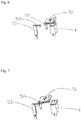
- the switch 5 includes a cover plate 51 shielding the extended power output interface 4, and a first terminal 52 connected to one electrode of the first set of battery cells 21 and a second terminal 53 connected to one electrode of the second set of the battery cells 22 which has different polarities with the electrode of the first set of battery cells 21.
- the connection and disconnection between the first terminal 52 and the second terminal 53 can be achieved through sliding the cover plate 51 to connect or disconnect the first terminal 52 to the second terminal 53.
- the first terminal 52 and the second terminal 53 are both connected to the circuit board 3.
- the first terminal 52 is connected to one electrode of the first battery cells 21 through the circuit board 3.
- the second terminal 53 is connected to one electrode of the second battery cells 22 though the circuit board 3.
- the electrode of the second battery cell 22 which is connected to the second terminal 53 has polarity different from the electrode of the first battery cell 21 which is connected to the first battery cell 21.
- the second terminal 53 includes a body portion (not labeled) and a clamping portion 531 extending from the body portion.
- the first terminal 52 is an insert piece disposed under the cover plate 51.
- the cover plate 51 is capable of sliding along a front to back direction of the battery pack 100.
- the first terminal 52 inserts into the clamping portion 531 of the second terminal 53 to establish the contact between the first terminal 52 and the second terminal 53.
- the first terminal 52 is provided with a terminal section (not labeled) at a lower end thereof to electrically connected with the circuit board 3 through a wire (not shown).
- the first terminal 52 and the second terminal 53 may be provided in other matching shapes, as long as the connection between the first terminal 52 and the second terminal 53 can be achieved.
- the case 1 is provided with an opening (not labeled) at a top surface thereof for receiving the extended power output interface 4.
- a stop block 8 is installed in the opening, as shown in Fig. 4 .
- the stop block 8 includes a main body 81, a groove 82 provided on the main body 81 for accommodating the cover plate 51, and a through hole 83 located below the groove 82 for mating with the extended power output interface 4.
- the cover plate 51 is moved horizontally on the stop block 8 to expose or cover the extended power output interface 4.
- An elastic element 9 is further provided between the cover plate 51 and the stop block 8. One end of the elastic element 9 is connected to the cover plate 51 and the other end of the elastic element 9 is connected to the stop block 8.
- the cover plate 51 is pushed by an external force so that the extended power output interface 4 is exposed.
- the cover plate 51 is reset under the action of the elastic element 9 in order to cover the extended power output interface 4.
- the elastic element 9 is preferably a torsion spring.
- the cover plate 51 When the battery pack 100 is supplying power for the external device, the cover plate 51 is pushed to be open by the external force to expose the extended power output interface 4 for supplying power to the external device When the external device is finished charging, the elastic element 9 resets the cover plate 51 to cover the extended power output interface 4.
- the extended power output interface 4 is not limited to the position shown in Fig. 1 , and it may be disposed at any appropriate position of the battery pack 100.
- the number of the extended power output interfaces 4 is not limited and could be one or multiple.
- the extended power output interface 4 may be a USB interface or other charging interfaces, which is not limited herein.
- a switch of a battery pack according to a second embodiment of the present invention is shown.
- the circuit board 3', the extended power output interface 4', the stop block 8', the elastic element 9' and other structures of the battery pack is substantially similar to the battery pack 100 in the first embodiment.
- the difference between the two embodiments is the structure of the switches. The following description will mainly describe the distinguishing features in detail, and the same features will not be described.
- the switch includes a cover plate 51', a conductive terminal 54' provided on the cover plate 51', and a first terminal 52' and a second terminal 53' which are electrically connected to the circuit board 3', respectively.
- the first terminal 52' and the second terminal 53' are provided separately from each other and connect to electrodes of different polarities of the first and second set of battery cells 21, 22 through the circuit board 3', respectively.
- the distance between the first terminal 52' and the second terminal 53' is not greater than the thickness of the conductive terminal 54', so that the conductive terminal 54' can contact the first terminal 52' and the second terminal 53' at the same time.
- the conductive terminal 54' is formed with conductive material.
- the conductive terminal 54' can be inserted into and clamped by the first and second terminals 52', 53' when the cover plate 51' is moved under the external force, so that the extended power output interface 4 can be exposed and the battery pack can supply power to the external device through the extended power output interface.
- the conductive terminal 54' may be provided in other shapes, as long as the connection between the first terminal 52' and the second terminal 53' can be achieved.
- a battery pack according to a third embodiment of the present invention is shown.
- the circuit board 3", the extended power output interface 4", the stop block 8", the elastic member 9", and other structures of the battery pack are substantially the same as the battery pack 100 described in the first embodiment.
- the difference in the first and third embodiment is the structure of the switches. The following description will mainly describe the distinguishing features in detail, and the same features will not be described.
- the switch includes a cover plate 51", a trigger terminal 54" provided on the cover plate 51", and a micro switch 55" electrically connected to the circuit board 3".
- the micro switch 55" includes a switch body, and a first terminal (not labeled) and a second terminal (not labeled) received in the switch body and electrically connected to the circuit board 3". The first terminal and the second terminal connect to the electrodes of different polarities of the first and second set of battery cells 21, 22 through the circuit board 3", respectively.
- the micro switch 55" further includes a contact point (not labeled) and a rectangular contact tab (not labeled) provided on the switch body. One end of the contact tab is fixed to the switch body and the other end is free.
- the contact point is located on the inner side of the contact tab and close to the fixed end of the contact tab.
- the contact tab repeatedly touches the contact point of the micro switch 55" by means of a lever.
- An elastic element (not shown) is provided between the contact tab and the switch body.
- the contact tab is actuated by the trigger terminal 54" to press the contact point and electrically connects the first terminal and the second terminal.
- the contact tab leaves the contact point under the action of the elastic element so that the contact point returns to an untriggered state, and the first terminal and the second terminal are disconnected.
- the trigger terminal 54" is preferably a plate which facilitates to push the contact tab to rotate.
- the beneficial effects of the present invention include: applying a switch in the battery pack to replace the single-chip microcomputer control switch to control the circuit which prevents the short circuit caused by the single-chip microcomputer misjudgment, and improves the safety of the battery pack when supplying power to the external devices.
Landscapes
- Chemical & Material Sciences (AREA)
- Chemical Kinetics & Catalysis (AREA)
- Electrochemistry (AREA)
- General Chemical & Material Sciences (AREA)
- Engineering & Computer Science (AREA)
- Manufacturing & Machinery (AREA)
- Power Engineering (AREA)
- Microelectronics & Electronic Packaging (AREA)
- Life Sciences & Earth Sciences (AREA)
- Biophysics (AREA)
- Computer Hardware Design (AREA)
- Battery Mounting, Suspending (AREA)
Priority Applications (1)
| Application Number | Priority Date | Filing Date | Title |
|---|---|---|---|
| EP22150957.3A EP4007118A1 (fr) | 2019-03-06 | 2020-03-06 | Bloc-batterie |
Applications Claiming Priority (1)
| Application Number | Priority Date | Filing Date | Title |
|---|---|---|---|
| CN201910167018.3A CN109713764B (zh) | 2019-03-06 | 2019-03-06 | 电池包 |
Related Child Applications (1)
| Application Number | Title | Priority Date | Filing Date |
|---|---|---|---|
| EP22150957.3A Division EP4007118A1 (fr) | 2019-03-06 | 2020-03-06 | Bloc-batterie |
Publications (2)
| Publication Number | Publication Date |
|---|---|
| EP3706284A1 true EP3706284A1 (fr) | 2020-09-09 |
| EP3706284B1 EP3706284B1 (fr) | 2022-01-12 |
Family
ID=66266219
Family Applications (2)
| Application Number | Title | Priority Date | Filing Date |
|---|---|---|---|
| EP20161605.9A Active EP3706284B1 (fr) | 2019-03-06 | 2020-03-06 | Bloc-batterie |
| EP22150957.3A Pending EP4007118A1 (fr) | 2019-03-06 | 2020-03-06 | Bloc-batterie |
Family Applications After (1)
| Application Number | Title | Priority Date | Filing Date |
|---|---|---|---|
| EP22150957.3A Pending EP4007118A1 (fr) | 2019-03-06 | 2020-03-06 | Bloc-batterie |
Country Status (4)
| Country | Link |
|---|---|
| US (2) | US11211665B2 (fr) |
| EP (2) | EP3706284B1 (fr) |
| CN (1) | CN109713764B (fr) |
| ES (1) | ES2907051T3 (fr) |
Families Citing this family (16)
| Publication number | Priority date | Publication date | Assignee | Title |
|---|---|---|---|---|
| USD894120S1 (en) * | 2018-11-21 | 2020-08-25 | Wurth International Ag | Battery |
| USD924793S1 (en) * | 2019-02-13 | 2021-07-13 | Globe (jiangsu) Co., Ltd. | Battery |
| US11424504B2 (en) | 2019-08-09 | 2022-08-23 | Techtronic Cordless Gp | Battery pack support portion configured to accommodate multiple different device interfaces |
| CN117477067A (zh) * | 2020-06-09 | 2024-01-30 | 格力博(江苏)股份有限公司 | 电池包 |
| CN111682615A (zh) * | 2020-06-18 | 2020-09-18 | 格力博(江苏)股份有限公司 | 充电控制电路、充电装置及充电系统 |
| WO2022068690A1 (fr) * | 2020-09-30 | 2022-04-07 | 南京德朔实业有限公司 | Bloc-batterie, système d'outil électrique et système de charge |
| US20220311081A1 (en) * | 2021-03-26 | 2022-09-29 | Sion Power Corporation | Battery pack and related components and methods |
| USD1116993S1 (en) * | 2021-04-24 | 2026-03-10 | Jiangsu Dongcheng Tools Technology Co., Ltd. | Battery pack |
| CN115765064A (zh) * | 2021-09-06 | 2023-03-07 | 格力博(江苏)股份有限公司 | 一种电源系统及该系统与工具的组合 |
| USD1083779S1 (en) * | 2023-01-31 | 2025-07-15 | Makita Corporation | Battery |
| JP1750674S (ja) * | 2023-01-31 | 2023-08-10 | 蓄電池 | |
| JP1748243S (ja) * | 2023-01-31 | 2023-07-07 | 蓄電池 | |
| JP1748242S (ja) * | 2023-01-31 | 2023-07-07 | 蓄電池 | |
| USD1083777S1 (en) * | 2023-01-31 | 2025-07-15 | Makita Corporation | Battery |
| USD1086988S1 (en) * | 2023-07-19 | 2025-08-05 | Carlos Bolsi Gavagnin | Battery pack |
| USD1027826S1 (en) * | 2023-08-14 | 2024-05-21 | Minhui Wang | Lithium battery |
Citations (4)
| Publication number | Priority date | Publication date | Assignee | Title |
|---|---|---|---|---|
| US4957831A (en) * | 1988-03-04 | 1990-09-18 | Black & Decker, Inc. | Control apparatus for switching a battery pack |
| WO2018008816A1 (fr) * | 2016-07-06 | 2018-01-11 | 유대영 | Chargeur et son procédé d'actionnement |
| KR101845793B1 (ko) * | 2016-11-10 | 2018-04-06 | 김영조 | 보조배터리 겸용 휴대용 멀티 전원제어팩 장치 |
| KR20180037636A (ko) * | 2016-10-04 | 2018-04-13 | 김영조 | 보조배터리 겸용 휴대용 멀티 전원제어팩 장치 |
Family Cites Families (11)
| Publication number | Priority date | Publication date | Assignee | Title |
|---|---|---|---|---|
| TWI255572B (en) | 2004-05-05 | 2006-05-21 | Advanced Connectek Inc | A portable electrical power unit with transmission display |
| JP4101205B2 (ja) * | 2004-05-11 | 2008-06-18 | 松下電器産業株式会社 | 電池パック及び電源装置 |
| US20080150474A1 (en) | 2006-10-27 | 2008-06-26 | Ingersoll-Rand Company | Cordless power tool battery charging and analyzing system |
| TW201240270A (en) * | 2011-03-18 | 2012-10-01 | Samya Technology Co Ltd | Integrated battery charger |
| WO2012164761A1 (fr) * | 2011-05-31 | 2012-12-06 | 日立ビークルエナジー株式会社 | Dispositif de surveillance de système de batteries |
| US9620989B2 (en) | 2013-03-13 | 2017-04-11 | Blackbird Tech Llc | Rechargeable battery accessories |
| KR101455035B1 (ko) * | 2014-07-28 | 2014-11-04 | 대한민국(육군참모총장) | 이차전지팩이 내장된 휴대용 전원공급장치 |
| US9917457B2 (en) | 2015-02-02 | 2018-03-13 | Black & Decker Inc. | Power tool with USB connection |
| WO2017167210A1 (fr) * | 2016-03-30 | 2017-10-05 | 南京德朔实业有限公司 | Système de charge pour batterie d'automobile, dispositif de conversion et procédé de charge |
| JP6863388B2 (ja) * | 2016-10-31 | 2021-04-21 | 工機ホールディングス株式会社 | 電池パック |
| CN209562182U (zh) * | 2019-03-06 | 2019-10-29 | 常州格力博有限公司 | 电池包 |
-
2019
- 2019-03-06 CN CN201910167018.3A patent/CN109713764B/zh active Active
-
2020
- 2020-03-06 ES ES20161605T patent/ES2907051T3/es active Active
- 2020-03-06 US US16/811,061 patent/US11211665B2/en active Active
- 2020-03-06 EP EP20161605.9A patent/EP3706284B1/fr active Active
- 2020-03-06 EP EP22150957.3A patent/EP4007118A1/fr active Pending
-
2021
- 2021-11-17 US US17/528,763 patent/US11600884B2/en active Active
Patent Citations (4)
| Publication number | Priority date | Publication date | Assignee | Title |
|---|---|---|---|---|
| US4957831A (en) * | 1988-03-04 | 1990-09-18 | Black & Decker, Inc. | Control apparatus for switching a battery pack |
| WO2018008816A1 (fr) * | 2016-07-06 | 2018-01-11 | 유대영 | Chargeur et son procédé d'actionnement |
| KR20180037636A (ko) * | 2016-10-04 | 2018-04-13 | 김영조 | 보조배터리 겸용 휴대용 멀티 전원제어팩 장치 |
| KR101845793B1 (ko) * | 2016-11-10 | 2018-04-06 | 김영조 | 보조배터리 겸용 휴대용 멀티 전원제어팩 장치 |
Also Published As
| Publication number | Publication date |
|---|---|
| EP3706284B1 (fr) | 2022-01-12 |
| ES2907051T3 (es) | 2022-04-21 |
| US20220077533A1 (en) | 2022-03-10 |
| CN109713764B (zh) | 2024-03-12 |
| CN109713764A (zh) | 2019-05-03 |
| US11600884B2 (en) | 2023-03-07 |
| EP4007118A1 (fr) | 2022-06-01 |
| US11211665B2 (en) | 2021-12-28 |
| US20200287176A1 (en) | 2020-09-10 |
Similar Documents
| Publication | Publication Date | Title |
|---|---|---|
| US11600884B2 (en) | Battery pack | |
| US11664540B2 (en) | Power tool system and battery pack thereof | |
| EP3660949B1 (fr) | Système d'outil électrique et bolc-batterie correspondant | |
| US6384575B1 (en) | Battery charger capable of charging different size of batteries | |
| US20230395948A1 (en) | Battery pack | |
| CN212366135U (zh) | 电池包、工具系统及充电系统 | |
| CN203014411U (zh) | 电池可扩展移动电源 | |
| CN111584788A (zh) | 电动工具及电动工具系统 | |
| CN111725458A (zh) | 电池包及具有该电池包的电动工具系统 | |
| WO1999066605A1 (fr) | Ensemble fiche | |
| US20070018609A1 (en) | Battery charger | |
| CN209562182U (zh) | 电池包 | |
| CN111584789A (zh) | 电动工具及其系统 | |
| CN103825319B (zh) | 一种充电器 | |
| CN212113850U (zh) | 电池包及具有该电池包的电动工具系统 | |
| CN202004197U (zh) | 可转换插头组合 | |
| CN104795867B (zh) | 多接口移动电源 | |
| CN210167823U (zh) | 多国充电器结构 | |
| CN222996271U (zh) | 锂离子电池组 | |
| CN212136767U (zh) | 一种结构模块化的立体转接插座 | |
| CN102064411B (zh) | 可转换插头组件 | |
| CN221687866U (zh) | 一种数据伸缩线应用于电源转换器上的导通结构 | |
| CN105047838B (zh) | 电池舱组 | |
| CN222980918U (zh) | 一种插头及锂离子电池 | |
| CN211829436U (zh) | 一种插拔式墙体插座 |
Legal Events
| Date | Code | Title | Description |
|---|---|---|---|
| PUAI | Public reference made under article 153(3) epc to a published international application that has entered the european phase |
Free format text: ORIGINAL CODE: 0009012 |
|
| STAA | Information on the status of an ep patent application or granted ep patent |
Free format text: STATUS: THE APPLICATION HAS BEEN PUBLISHED |
|
| AK | Designated contracting states |
Kind code of ref document: A1 Designated state(s): AL AT BE BG CH CY CZ DE DK EE ES FI FR GB GR HR HU IE IS IT LI LT LU LV MC MK MT NL NO PL PT RO RS SE SI SK SM TR |
|
| AX | Request for extension of the european patent |
Extension state: BA ME |
|
| RAP1 | Party data changed (applicant data changed or rights of an application transferred) |
Owner name: GLOBE (JIANGSU) CO., LTD. |
|
| STAA | Information on the status of an ep patent application or granted ep patent |
Free format text: STATUS: REQUEST FOR EXAMINATION WAS MADE |
|
| 17P | Request for examination filed |
Effective date: 20210309 |
|
| RBV | Designated contracting states (corrected) |
Designated state(s): AL AT BE BG CH CY CZ DE DK EE ES FI FR GB GR HR HU IE IS IT LI LT LU LV MC MK MT NL NO PL PT RO RS SE SI SK SM TR |
|
| RIC1 | Information provided on ipc code assigned before grant |
Ipc: H02J 7/00 20060101AFI20210521BHEP Ipc: H01R 13/70 20060101ALI20210521BHEP Ipc: H01M 50/20 20210101ALI20210521BHEP Ipc: H01M 10/42 20060101ALI20210521BHEP Ipc: B60L 58/19 20190101ALN20210521BHEP Ipc: H01R 13/453 20060101ALN20210521BHEP |
|
| GRAP | Despatch of communication of intention to grant a patent |
Free format text: ORIGINAL CODE: EPIDOSNIGR1 |
|
| STAA | Information on the status of an ep patent application or granted ep patent |
Free format text: STATUS: GRANT OF PATENT IS INTENDED |
|
| INTG | Intention to grant announced |
Effective date: 20210813 |
|
| GRAS | Grant fee paid |
Free format text: ORIGINAL CODE: EPIDOSNIGR3 |
|
| GRAA | (expected) grant |
Free format text: ORIGINAL CODE: 0009210 |
|
| STAA | Information on the status of an ep patent application or granted ep patent |
Free format text: STATUS: THE PATENT HAS BEEN GRANTED |
|
| AK | Designated contracting states |
Kind code of ref document: B1 Designated state(s): AL AT BE BG CH CY CZ DE DK EE ES FI FR GB GR HR HU IE IS IT LI LT LU LV MC MK MT NL NO PL PT RO RS SE SI SK SM TR |
|
| REG | Reference to a national code |
Ref country code: GB Ref legal event code: FG4D |
|
| REG | Reference to a national code |
Ref country code: CH Ref legal event code: EP |
|
| REG | Reference to a national code |
Ref country code: DE Ref legal event code: R096 Ref document number: 602020001562 Country of ref document: DE |
|
| REG | Reference to a national code |
Ref country code: IE Ref legal event code: FG4D |
|
| REG | Reference to a national code |
Ref country code: AT Ref legal event code: REF Ref document number: 1463017 Country of ref document: AT Kind code of ref document: T Effective date: 20220215 |
|
| REG | Reference to a national code |
Ref country code: SE Ref legal event code: TRGR |
|
| REG | Reference to a national code |
Ref country code: ES Ref legal event code: FG2A Ref document number: 2907051 Country of ref document: ES Kind code of ref document: T3 Effective date: 20220421 |
|
| REG | Reference to a national code |
Ref country code: LT Ref legal event code: MG9D |
|
| REG | Reference to a national code |
Ref country code: NL Ref legal event code: MP Effective date: 20220112 |
|
| REG | Reference to a national code |
Ref country code: AT Ref legal event code: MK05 Ref document number: 1463017 Country of ref document: AT Kind code of ref document: T Effective date: 20220112 |
|
| PG25 | Lapsed in a contracting state [announced via postgrant information from national office to epo] |
Ref country code: NL Free format text: LAPSE BECAUSE OF FAILURE TO SUBMIT A TRANSLATION OF THE DESCRIPTION OR TO PAY THE FEE WITHIN THE PRESCRIBED TIME-LIMIT Effective date: 20220112 |
|
| PG25 | Lapsed in a contracting state [announced via postgrant information from national office to epo] |
Ref country code: RS Free format text: LAPSE BECAUSE OF FAILURE TO SUBMIT A TRANSLATION OF THE DESCRIPTION OR TO PAY THE FEE WITHIN THE PRESCRIBED TIME-LIMIT Effective date: 20220112 Ref country code: PT Free format text: LAPSE BECAUSE OF FAILURE TO SUBMIT A TRANSLATION OF THE DESCRIPTION OR TO PAY THE FEE WITHIN THE PRESCRIBED TIME-LIMIT Effective date: 20220512 Ref country code: NO Free format text: LAPSE BECAUSE OF FAILURE TO SUBMIT A TRANSLATION OF THE DESCRIPTION OR TO PAY THE FEE WITHIN THE PRESCRIBED TIME-LIMIT Effective date: 20220412 Ref country code: LT Free format text: LAPSE BECAUSE OF FAILURE TO SUBMIT A TRANSLATION OF THE DESCRIPTION OR TO PAY THE FEE WITHIN THE PRESCRIBED TIME-LIMIT Effective date: 20220112 Ref country code: HR Free format text: LAPSE BECAUSE OF FAILURE TO SUBMIT A TRANSLATION OF THE DESCRIPTION OR TO PAY THE FEE WITHIN THE PRESCRIBED TIME-LIMIT Effective date: 20220112 Ref country code: BG Free format text: LAPSE BECAUSE OF FAILURE TO SUBMIT A TRANSLATION OF THE DESCRIPTION OR TO PAY THE FEE WITHIN THE PRESCRIBED TIME-LIMIT Effective date: 20220412 |
|
| PG25 | Lapsed in a contracting state [announced via postgrant information from national office to epo] |
Ref country code: PL Free format text: LAPSE BECAUSE OF FAILURE TO SUBMIT A TRANSLATION OF THE DESCRIPTION OR TO PAY THE FEE WITHIN THE PRESCRIBED TIME-LIMIT Effective date: 20220112 Ref country code: LV Free format text: LAPSE BECAUSE OF FAILURE TO SUBMIT A TRANSLATION OF THE DESCRIPTION OR TO PAY THE FEE WITHIN THE PRESCRIBED TIME-LIMIT Effective date: 20220112 Ref country code: GR Free format text: LAPSE BECAUSE OF FAILURE TO SUBMIT A TRANSLATION OF THE DESCRIPTION OR TO PAY THE FEE WITHIN THE PRESCRIBED TIME-LIMIT Effective date: 20220413 Ref country code: FI Free format text: LAPSE BECAUSE OF FAILURE TO SUBMIT A TRANSLATION OF THE DESCRIPTION OR TO PAY THE FEE WITHIN THE PRESCRIBED TIME-LIMIT Effective date: 20220112 Ref country code: AT Free format text: LAPSE BECAUSE OF FAILURE TO SUBMIT A TRANSLATION OF THE DESCRIPTION OR TO PAY THE FEE WITHIN THE PRESCRIBED TIME-LIMIT Effective date: 20220112 |
|
| PG25 | Lapsed in a contracting state [announced via postgrant information from national office to epo] |
Ref country code: IS Free format text: LAPSE BECAUSE OF FAILURE TO SUBMIT A TRANSLATION OF THE DESCRIPTION OR TO PAY THE FEE WITHIN THE PRESCRIBED TIME-LIMIT Effective date: 20220512 |
|
| REG | Reference to a national code |
Ref country code: DE Ref legal event code: R097 Ref document number: 602020001562 Country of ref document: DE |
|
| PG25 | Lapsed in a contracting state [announced via postgrant information from national office to epo] |
Ref country code: SM Free format text: LAPSE BECAUSE OF FAILURE TO SUBMIT A TRANSLATION OF THE DESCRIPTION OR TO PAY THE FEE WITHIN THE PRESCRIBED TIME-LIMIT Effective date: 20220112 Ref country code: SK Free format text: LAPSE BECAUSE OF FAILURE TO SUBMIT A TRANSLATION OF THE DESCRIPTION OR TO PAY THE FEE WITHIN THE PRESCRIBED TIME-LIMIT Effective date: 20220112 Ref country code: RO Free format text: LAPSE BECAUSE OF FAILURE TO SUBMIT A TRANSLATION OF THE DESCRIPTION OR TO PAY THE FEE WITHIN THE PRESCRIBED TIME-LIMIT Effective date: 20220112 Ref country code: MC Free format text: LAPSE BECAUSE OF FAILURE TO SUBMIT A TRANSLATION OF THE DESCRIPTION OR TO PAY THE FEE WITHIN THE PRESCRIBED TIME-LIMIT Effective date: 20220112 Ref country code: EE Free format text: LAPSE BECAUSE OF FAILURE TO SUBMIT A TRANSLATION OF THE DESCRIPTION OR TO PAY THE FEE WITHIN THE PRESCRIBED TIME-LIMIT Effective date: 20220112 Ref country code: DK Free format text: LAPSE BECAUSE OF FAILURE TO SUBMIT A TRANSLATION OF THE DESCRIPTION OR TO PAY THE FEE WITHIN THE PRESCRIBED TIME-LIMIT Effective date: 20220112 Ref country code: CZ Free format text: LAPSE BECAUSE OF FAILURE TO SUBMIT A TRANSLATION OF THE DESCRIPTION OR TO PAY THE FEE WITHIN THE PRESCRIBED TIME-LIMIT Effective date: 20220112 |
|
| PLBE | No opposition filed within time limit |
Free format text: ORIGINAL CODE: 0009261 |
|
| STAA | Information on the status of an ep patent application or granted ep patent |
Free format text: STATUS: NO OPPOSITION FILED WITHIN TIME LIMIT |
|
| PG25 | Lapsed in a contracting state [announced via postgrant information from national office to epo] |
Ref country code: AL Free format text: LAPSE BECAUSE OF FAILURE TO SUBMIT A TRANSLATION OF THE DESCRIPTION OR TO PAY THE FEE WITHIN THE PRESCRIBED TIME-LIMIT Effective date: 20220112 |
|
| REG | Reference to a national code |
Ref country code: BE Ref legal event code: MM Effective date: 20220331 |
|
| 26N | No opposition filed |
Effective date: 20221013 |
|
| PG25 | Lapsed in a contracting state [announced via postgrant information from national office to epo] |
Ref country code: LU Free format text: LAPSE BECAUSE OF NON-PAYMENT OF DUE FEES Effective date: 20220306 Ref country code: IE Free format text: LAPSE BECAUSE OF NON-PAYMENT OF DUE FEES Effective date: 20220306 |
|
| PG25 | Lapsed in a contracting state [announced via postgrant information from national office to epo] |
Ref country code: SI Free format text: LAPSE BECAUSE OF FAILURE TO SUBMIT A TRANSLATION OF THE DESCRIPTION OR TO PAY THE FEE WITHIN THE PRESCRIBED TIME-LIMIT Effective date: 20220112 Ref country code: BE Free format text: LAPSE BECAUSE OF NON-PAYMENT OF DUE FEES Effective date: 20220331 |
|
| REG | Reference to a national code |
Ref country code: CH Ref legal event code: PL |
|
| PG25 | Lapsed in a contracting state [announced via postgrant information from national office to epo] |
Ref country code: LI Free format text: LAPSE BECAUSE OF NON-PAYMENT OF DUE FEES Effective date: 20230331 Ref country code: CH Free format text: LAPSE BECAUSE OF NON-PAYMENT OF DUE FEES Effective date: 20230331 |
|
| PG25 | Lapsed in a contracting state [announced via postgrant information from national office to epo] |
Ref country code: MK Free format text: LAPSE BECAUSE OF FAILURE TO SUBMIT A TRANSLATION OF THE DESCRIPTION OR TO PAY THE FEE WITHIN THE PRESCRIBED TIME-LIMIT Effective date: 20220112 Ref country code: CY Free format text: LAPSE BECAUSE OF FAILURE TO SUBMIT A TRANSLATION OF THE DESCRIPTION OR TO PAY THE FEE WITHIN THE PRESCRIBED TIME-LIMIT Effective date: 20220112 |
|
| PG25 | Lapsed in a contracting state [announced via postgrant information from national office to epo] |
Ref country code: HU Free format text: LAPSE BECAUSE OF FAILURE TO SUBMIT A TRANSLATION OF THE DESCRIPTION OR TO PAY THE FEE WITHIN THE PRESCRIBED TIME-LIMIT; INVALID AB INITIO Effective date: 20200306 |
|
| PG25 | Lapsed in a contracting state [announced via postgrant information from national office to epo] |
Ref country code: TR Free format text: LAPSE BECAUSE OF FAILURE TO SUBMIT A TRANSLATION OF THE DESCRIPTION OR TO PAY THE FEE WITHIN THE PRESCRIBED TIME-LIMIT Effective date: 20220112 |
|
| PG25 | Lapsed in a contracting state [announced via postgrant information from national office to epo] |
Ref country code: MT Free format text: LAPSE BECAUSE OF FAILURE TO SUBMIT A TRANSLATION OF THE DESCRIPTION OR TO PAY THE FEE WITHIN THE PRESCRIBED TIME-LIMIT Effective date: 20220112 |
|
| PGFP | Annual fee paid to national office [announced via postgrant information from national office to epo] |
Ref country code: ES Payment date: 20250416 Year of fee payment: 6 |
|
| PGFP | Annual fee paid to national office [announced via postgrant information from national office to epo] |
Ref country code: IT Payment date: 20250331 Year of fee payment: 6 |
|
| PGFP | Annual fee paid to national office [announced via postgrant information from national office to epo] |
Ref country code: SE Payment date: 20260323 Year of fee payment: 7 |
|
| PGFP | Annual fee paid to national office [announced via postgrant information from national office to epo] |
Ref country code: GB Payment date: 20260324 Year of fee payment: 7 |
|
| PGFP | Annual fee paid to national office [announced via postgrant information from national office to epo] |
Ref country code: DE Payment date: 20260320 Year of fee payment: 7 |
|
| PGFP | Annual fee paid to national office [announced via postgrant information from national office to epo] |
Ref country code: FR Payment date: 20260325 Year of fee payment: 7 |