EP3706445A1 - Tragbares marines bakensystem - Google Patents
Tragbares marines bakensystem Download PDFInfo
- Publication number
- EP3706445A1 EP3706445A1 EP17930438.1A EP17930438A EP3706445A1 EP 3706445 A1 EP3706445 A1 EP 3706445A1 EP 17930438 A EP17930438 A EP 17930438A EP 3706445 A1 EP3706445 A1 EP 3706445A1
- Authority
- EP
- European Patent Office
- Prior art keywords
- transmitter
- receiver
- interface
- beacon system
- marine beacon
- Prior art date
- Legal status (The legal status is an assumption and is not a legal conclusion. Google has not performed a legal analysis and makes no representation as to the accuracy of the status listed.)
- Pending
Links
Images

Classifications
-
- G—PHYSICS
- G08—SIGNALLING
- G08B—SIGNALLING SYSTEMS, e.g. PERSONAL CALLING SYSTEMS; ORDER TELEGRAPHS; ALARM SYSTEMS
- G08B21/00—Alarms responsive to a single specified undesired or abnormal condition and not otherwise provided for
- G08B21/02—Alarms for ensuring the safety of persons
- G08B21/0202—Child monitoring systems using a transmitter-receiver system carried by the parent and the child
- G08B21/0272—System arrangements wherein the object is to detect exact location of child or item using triangulation other than GPS
-
- H—ELECTRICITY
- H04—ELECTRIC COMMUNICATION TECHNIQUE
- H04W—WIRELESS COMMUNICATION NETWORKS
- H04W4/00—Services specially adapted for wireless communication networks; Facilities therefor
- H04W4/30—Services specially adapted for particular environments, situations or purposes
-
- G—PHYSICS
- G01—MEASURING; TESTING
- G01S—RADIO DIRECTION-FINDING; RADIO NAVIGATION; DETERMINING DISTANCE OR VELOCITY BY USE OF RADIO WAVES; LOCATING OR PRESENCE-DETECTING BY USE OF THE REFLECTION OR RERADIATION OF RADIO WAVES; ANALOGOUS ARRANGEMENTS USING OTHER WAVES
- G01S19/00—Satellite radio beacon positioning systems; Determining position, velocity or attitude using signals transmitted by such systems
- G01S19/01—Satellite radio beacon positioning systems transmitting time-stamped messages, e.g. GPS [Global Positioning System], GLONASS [Global Orbiting Navigation Satellite System] or GALILEO
- G01S19/13—Receivers
- G01S19/14—Receivers specially adapted for specific applications
- G01S19/17—Emergency applications
-
- G—PHYSICS
- G08—SIGNALLING
- G08B—SIGNALLING SYSTEMS, e.g. PERSONAL CALLING SYSTEMS; ORDER TELEGRAPHS; ALARM SYSTEMS
- G08B25/00—Alarm systems in which the location of the alarm condition is signalled to a central station, e.g. fire or police telegraphic systems
- G08B25/01—Alarm systems in which the location of the alarm condition is signalled to a central station, e.g. fire or police telegraphic systems characterised by the transmission medium
- G08B25/10—Alarm systems in which the location of the alarm condition is signalled to a central station, e.g. fire or police telegraphic systems characterised by the transmission medium using wireless transmission systems
-
- G—PHYSICS
- G08—SIGNALLING
- G08B—SIGNALLING SYSTEMS, e.g. PERSONAL CALLING SYSTEMS; ORDER TELEGRAPHS; ALARM SYSTEMS
- G08B5/00—Visible signalling systems, e.g. visible personal calling systems or remote indication of seats occupied
- G08B5/002—Distress signalling devices, e.g. rescue balloons
-
- H—ELECTRICITY
- H02—GENERATION; CONVERSION OR DISTRIBUTION OF ELECTRIC POWER
- H02J—ELECTRIC POWER NETWORKS; CIRCUIT ARRANGEMENTS OR SYSTEMS FOR SUPPLYING OR DISTRIBUTING ELECTRIC POWER; SYSTEMS FOR STORING ELECTRIC ENERGY
- H02J7/00—Circuit arrangements for charging or discharging batteries or for supplying loads from batteries
- H02J7/02—Circuit arrangements for charging or discharging batteries or for supplying loads from batteries for charging batteries from AC mains by converters
-
- H—ELECTRICITY
- H04—ELECTRIC COMMUNICATION TECHNIQUE
- H04W—WIRELESS COMMUNICATION NETWORKS
- H04W4/00—Services specially adapted for wireless communication networks; Facilities therefor
- H04W4/02—Services making use of location information
- H04W4/029—Location-based management or tracking services
-
- G—PHYSICS
- G08—SIGNALLING
- G08B—SIGNALLING SYSTEMS, e.g. PERSONAL CALLING SYSTEMS; ORDER TELEGRAPHS; ALARM SYSTEMS
- G08B21/00—Alarms responsive to a single specified undesired or abnormal condition and not otherwise provided for
- G08B21/02—Alarms for ensuring the safety of persons
- G08B21/0202—Child monitoring systems using a transmitter-receiver system carried by the parent and the child
- G08B21/0261—System arrangements wherein the object is to detect trespassing over a fixed physical boundary, e.g. the end of a garden
-
- H—ELECTRICITY
- H04—ELECTRIC COMMUNICATION TECHNIQUE
- H04W—WIRELESS COMMUNICATION NETWORKS
- H04W4/00—Services specially adapted for wireless communication networks; Facilities therefor
- H04W4/02—Services making use of location information
-
- H—ELECTRICITY
- H04—ELECTRIC COMMUNICATION TECHNIQUE
- H04W—WIRELESS COMMUNICATION NETWORKS
- H04W4/00—Services specially adapted for wireless communication networks; Facilities therefor
- H04W4/90—Services for handling of emergency or hazardous situations, e.g. earthquake and tsunami warning systems [ETWS]
-
- H—ELECTRICITY
- H04—ELECTRIC COMMUNICATION TECHNIQUE
- H04W—WIRELESS COMMUNICATION NETWORKS
- H04W84/00—Network topologies
- H04W84/02—Hierarchically pre-organised networks, e.g. paging networks, cellular networks, WLAN [Wireless Local Area Network] or WLL [Wireless Local Loop]
- H04W84/10—Small scale networks; Flat hierarchical networks
- H04W84/12—WLAN [Wireless Local Area Networks]
Definitions
- the invention is related to a beacon tracking system, and more particularly to a portable real-time tracking system for providing personal offshore/inland location/danger alert and precautionary safety protection functions for marine activities.
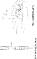
- FIGS. 1a and 1b respectively show a conventional surface marker buoy 100 used by the divers and a diver holding such surface marker buoy 100.
- the surface marker buoy 100 is 100-150 centimeters in length and 10-15 centimeters in diameter and is tangerine colored.
- the surface marker buoy 100 is used to protect the diver from being hit by vessels when he/she breaks the surface.
- this surface marker buoy 100 fails to transmit wireless signal and can only help if the visuality is good. In the event of loss of contact by drifting, the surface marker buoy is of little help for rescue operation.
- PLB personal locator beacon
- DISTRESS function the major shortcoming of PLB is that once the distress signal is sent, the Cospas-Sarsat system notifies salvage unit to start rescue operation. As a result, there is no way to verify its reliability before an accident.
- the PLB can either provide real-time tracking for the vessels to avoid an impact accident.
- the PLB cannot be used to call the vessels to pick up the divers.
- the waterproof performance of commercially available PLB is not suitable for divers(IP67).
- a walkie-talkie type marine safety device for diver has been proposed.
- This device employs analog signal with communication range typically less than 3 kilometers. If a great number of people use this device at the same time, mutual interference would occur. Due to limited effective communication range, this device is help little in marine rescue.
- Other relevant device uses AIS (Automatic Identification System) channel to send the distress signal in event of accident to pretend as a shipwreck accident.
- AIS distress signal requires the Maritime Mobile Service Identity (MMSI). This means that the diver must have a MMSI for his own, and the nearby vessels must be equipped with a VHF AIS receiver to make the distress call to be valid.
- MMSI Maritime Mobile Service Identity
- An object of the invention is to provide a marine beacon system for addressing the deficiencies of the prior art.
- a transmitter carried by individual, a receiver installed on the vessel or installed onshore, and a smart device compose a personal safety monitoring and tracking solution for marine activities.
- the system employs a built-in communication protocol with time division technique to effectively achieve multiple(transmitters)-to-multiple(receivers) communication with a single RF channel. That is, it can let multiple transmitters and multiple receivers to be used at the same time without compromising the communication quality.
- the invention provides a portable marine beacon system, including at least one transmitter, at least one receiver, and at least one smart device.
- Each of the at least one transmitter is carried by one user.
- Each of the at least one receiver may be placed on a vessel, on the coast, or in land, and conduct RF wireless communication with the at least one transmitter to receive data therefrom.
- the smart device can conduct Wi-Fi communication with the at least one receiver to receive and process data of the at least one receiver respectively.
- Each of the at least one smart device includes a central processing unit (CPU), a main memory, and a touch screen.
- the main memory includes an App for real-time tracking of transmitters.
- the CPU is instructed to execute the App having a Transmitter Management Interface, an Activity Planning Interface (or Alert Setting Interface), a Security Patrol Interface (or Safety Surveillance/Monitoring Interface), and a Record Playback Interface (or History Playback Interface) through the touch screen to provide the user offshore and onshore positioning/distress alert and precautionary safety protection functions for marine activities.
- a Transmitter Management Interface or Alert Setting Interface
- a Security Patrol Interface or Safety Surveillance/Monitoring Interface
- Record Playback Interface or History Playback Interface
- the transmitter includes a mainboard, a wireless charging module, an illumination and display module, a power supply unit, and a global positioning system (GPS) module.
- the mainboard has a microprocessor (MCU), a main memory, a RF module, and multiple magnetic sensors.
- the RF module includes an antenna. These magnetic sensors convert magnetic variation into voltage high/low alteration as an ON/OFF control signal to the microprocessor.
- the GPS module includes a GPS antenna for positioning.
- the wireless charging module is wirelessly powered by a charging mat from outside to charge the battery and power supply unit.
- the power supply unit supply power to the mainboard, the illumination and display module, the GPS module.
- the receiver includes a mainboard, a wireless charging module, an illumination and display module, a power supply unit, and a Wi-Fi module.
- the mainboard has a microprocessor (MCU), a main memory, a RF module, and multiple magnetic sensors.
- the RF module includes an antenna. These magnetic sensors convert magnetic variation into voltage high/low alteration as an ON/OFF control signal to the microprocessor.
- the Wi-Fi module includes an antenna for communicating with the smart device.
- the wireless charging module is wirelessly powered by a charging mat from outside to charge the battery and power supply unit.
- the power supply unit supply power to the mainboard, the illumination and display module, the Wi-Fi module.
- the transmitter and the receiver can be integrated into a transceiver which can be set for operation of a transmitter or a receiver by switching the switches.
- transceiver The front of transceiver is designed with five slide switches, including: (1) an illumination switch; (2) a receiver setting switch; (3) a transmitter setting switch; (4) a transmitter DISTRESS function switch; and (5) a transmitter OK function switch.
- transceiver can be set to an auto-testing mode for the transmitter thereof to transmit the auto-testing data to the receiver of another transceiver and display these data on the touch screen of a corresponding smart device through Wi-Fi communication.
- the transceiver can be set to a transmitter mode.
- the tracking data can be sent by the transmitter setting switch and a built-in firmware.
- the tracking data include: (1) an identification code; (2) a latitude and a longitude; and (3) a status code.
- the status code can indicate four status: OK status, DISTRESS status, DISTRESS TERMINATING status and TESTING status. Under the TESTING status, the transceiver can transmit the auto-testing data.
- the auto-testing data include: a model number of the transmitter; an indication of whether switching functions of all the switches is normal; a remaining power level of the battery; and an indication of whether the GPS positioning is successful and its positioned latitude and longitude.
- the transceiver can be set to a receiver mode.
- the receiver can receive the identification code of the transmitter, the latitude and the longitude; the status code, and the auto-testing data at the same time, and send these data to a corresponding smart device through Wi-Fi communication.
- the central processing unit (CPU) of the corresponding smart device can execute the App for real-time tracking and manage, analyze, record, and share these data to provide the distress alert and precautionary safety protection functions by manipulating the touch screen.
- the Security Patrol Interface (or Safety Surveillance/Monitoring Interface) of the touch screen has the following features: (1) automatic interconnection of the receiver and the smart device; (2) touch panel operation; (3) provide pull-down function menus on the left and right sides of the screen; (4) display of navigation direction; (5) display of proportional scale; (6) display of a compass; (7) zoom-in/out of the radar chart; and (8) browsing and scrolling operation of the radar chart.
- the Transmitter Management Interface has the following functions: (1) quick selection of IDs of transmitters and grouping; (2) display of the auto-testing data of the transmitter and the receiver.
- the Activity Planning Interface (or Alert Setting Interface) has the following functions: configuration of a safe zone range and a safe time range of an activity for each group set through the Transmitter Management Interface.
- the Security Patrol Interface (or Safety Surveillance/Monitoring Interface) provides the following functions: (1) monitoring the ID/location/status data of all activity players on a real-time basis; (2) in the event of hazard, the App automatically activates an audible alarm and on-screen alerts. These alerts have four following type : (2d) DISTRESS (SOS) alert and other precautionary alerts for safety protection : (2a) human-vessel impact (collision) alert; (2b) loss of signal (over time) alert; (2c) out of safe zone (over distance) alert.
- SOS DISTRESS
- the Record Playback Interface (or History Playback Interface) has the functions of replaying, sharing, deleting, and recording historical GPS data of the at least one transmitter throughout entire period of an activity.
- the smart device may be a smartphone, a tablet computer, or a laptop computer.
- One of the advantages of the invention is that the receiver and the transmitter can be integrated into a single transceiver. This can simplify the manufacturing process, enhance the yield, simplify the certification procedure in different countries and lower the certification cost.
- Another advantage of the invention is that all the modules within the transmitter and the receiver are not connected to each other with cables but with board-to-board connectors. This can suppress the adverse temperature effect against the sheath of the cables, thus enhancing the yield of assembly and prolonging the lifespan of the transceiver.
- transmitter and the receiver employ inductive magnetic switch and a wireless charging technique to render a seamless housing surface, which would in turn result in a high-level hermetic and waterproof performance.
- the invention possesses an advantage that the transmitter and the receiver employ a built-in communication protocol and a time-division technique to achieve multiple (transmitters) to multiple (receivers) communication simultaneously with a single RF channel.
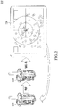
- the portable marine beacon system 200 includes a transmitter 210, a receiver 220, and a smart device 230.
- the transmitter 210 is used to transmit radio frequency (RF) signals to the receiver 220.
- the receiver 220 then forwards the received signals to the smart device 230 by way of Wi-Fi transmission.
- the smart device 230 displays ID/location/status data on a touch screen of the smart device 230.
- RF radio frequency
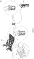
- a diver 350 transmits the ID/location/status data to the receiver 320 by RF communications through the transmitter 310.
- the receiver 320 then transmits the received ID/location/status data to the smart device 330 by way of Wi-Fi communication.
- the ID/location/status data is shown on the touch screen of the device 230.
- the receiver 320 and the smart device 230 are placed on a vessel 340 or placed offshore or onshore.
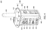
- the transceiver 400 includes an outer upper housing 421, a transparent outer lower housing 422, a waterproof O-ring (placed between the outer upper housing and the outer lower housing, not shown), an internal housing 430, a switch guiding plate 410, five slide switches 411-415, an illumination LED cover 450, a display bezel 460, a company logo 470, a projecting RF antenna 423, multiple screws 441, and a bottom bolt 442.
- the outer upper housing 421 and the transparent outer lower housing 422 are integrated in an up-and-down direction.
- the waterproof O-ring is placed between the outer upper housing 421 and the transparent outer lower housing 422 to form an outer housing 480.
- the multiple screws 441 are used to lock and seal the outer upper housing 421 and the outer lower housing 422.
- the transparent outer lower housing 422 is mounted outside the internal housing 430 to wrap around the internal housing 430.
- the switch guiding plate 410 is mounted on a front surface of the outer lower housing 422 with the five slide switches 411-415 mounted thereon (the five slide switches 411-415 will be discussed in detail later). Each slide switch can be slid left and right along a sliding track in one of five sliding grooves of the switch guiding plate 410.
- the illumination LED cover 450 is round, and the display bezel 460 is rectangular. Viewed from the front surface of the internal housing 430, both the illumination LED cover 450 and the display bezel 460 are mounted on the right side of internal housing 430.
- the company logo 470 is oval and is mounted on a top surface of the external upper housing 421.
- the projecting RF antenna 423 of the outer upper housing 421 is sheathed for protection.
- the transparent outer lower housing 422 is provided with a bottom bolt 442 to fasten its bottom.
- the five slide switches that are mounted on the front surface of the transceiver 400 are: (1) an illumination switch 411; (2) a receiver setting switch 412; (3) a transmitter setting switch 413; (4) a transmitter DISTRESS function switch 414; and (5) a transmitter OK function switch 415.
- the transceiver is set to be under a auto-testing mode for transmitter to transmit the auto-testing data of the transmitter to the receiver.
- the auto-testing data are then displayed on the touch screen of the smart device 230 by way of Wi-Fi communication.
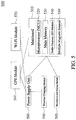
- the transceiver 500 includes a mainboard 510, a GPS module 560, a Wi-Fi module 570, a power supply unit 580, a wireless charging module 590, and an illumination and display module 595.
- the mainboard 510 is provided with a microprocessor (MCU) 520, a main memory 530, a radio frequency (RF) module 540, and multiple magnetic sensors 550.
- the RF module 540 includes an antenna. These magnetic sensors 550 are used to convert magnetic variation into voltage high/low alteration as an ON/OFF control signal to the microprocessor (MCU) 520.
- the wireless charging module 590 is wirelessly powered by a charging mat from outside to charge the battery and power supply unit.
- the power supply unit 580 is used to supply power to each module inside the transceiver.
- the GPS module 560 includes an antenna for GPS positioning.
- the Wi-Fi module 570 includes an antenna for communicating with the smart device 230.
- the magnetic sensors 550 can sense the magnetic variation arising from operation of external (magnetic) switches.
- the transceiver 500 can be set in a transmitter mode. Under this condition, the Wi-Fi module 570 is not needed to be activated. Alternatively, the transceiver 500 can be also set in a receiver mode. Under this condition, the Wi-Fi module 570 is needed to be activated.
- the mainboard 510-550 and each module 560-595 shown in FIG. 5 are mounted inside the internal housing 430 shown in FIG. 4 .
- the power supply unit 580 includes two 2600-3200 mAh rechargeable lithium batteries. These rechargeable lithium batteries can last at least 60 hours for continuous operation under the transmitter mode. Under the standby mode, these rechargeable lithium batteries can sustain for more than one week.
- the weight of the transceiver 400 is about 290 grams.
- the dimensions (height, width, depth) of the transceiver 400 are 10.2x6.7x5.7 centimeter/6.1 ⁇ 1.5 centimeter (height, diameter of antenna).
- the maximum communication range is about 100 kilometers.
- the suitable operating temperature is 0-60°C.
- the outer housing 480 is made of polycarbonate (PC).
- the outer lower housing 422 is transparent.
- the outer upper housing 421 usually has the same color with the internal housing 430.
- the internal housing 430 is made of acrylonitrile butadiene styrene (ABS) and may be colored in a variety of colors.
- ABS acrylonitrile butadiene styrene
- the specification of the internal housing of the invention should not be limited to the accurate form disclosed herein.
- the transmitter is analogous to a radio broadcasting station
- the receiver is analogous to a radio receiver.
- Each receiver can monitor more than 100 transmitters at the same time to achieve multiple (transmitters)-to-multiple (receivers) communication in a time-division manner with only a single RF channel.
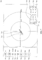
- a Transmitter Management Interface of the portable marine beacon system has the following functions : (1) quick selection of transmitters/IDs and grouping, as indicated by the reference numerals 610, 620, 630, 692, 693, 694 of FIG. 6 ; and ( 2 ) display of the auto-testing data of the transmitter and the receiver, as indicated by the reference numerals 601, 640, 650.
- FIG. 6 a Transmitter Management Interface of the portable marine beacon system has the following functions : (1) quick selection of transmitters/IDs and grouping, as indicated by the reference numerals 610, 620, 630, 692, 693, 694 of FIG. 6 ; and ( 2 ) display of the auto-testing data of the transmitter and the receiver, as indicated by the reference numerals 601, 640, 650.
- a table header on the uppermost row represents: 610: transmitters ID (click this field and the whole column is resorted); 620: Code/Set ID code to display; 630: Group/Set groups; 640: Tx Mode/Transmitter(Personnel) status; 650: System/Display if system check is pass.
- a left-side pull-down function menu includes: 691: Tx/Redirect to the Transmitter Management Interface; 692: Record/Store configuration data; 693: Show/Hide or show the entire transmitters to the display list; 694: Test/Add transmitters under test to the display list; 695: Plan/Redirect to the Activity planning Interface (or the Alert Setting Interface); 696: Surv/Redirect to the Security Patrol Interface (or the Safety Surveillance/Monitoring Interface); 697: PB/Redirect to the Record Playback Interface (or the History Playback Interface); 698 Help/Get help from users guide.
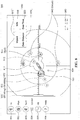
- the Activity planning Interface (or the Alert Setting Interface) of the portable marine beacon system according to the invention is illustrated.
- this interface has the following functions to ensure that based on the groups set by the Transmitters Management Interface, the safe activity range and activity planning for each group can be configured.
- 7 its left-side pull-down function menu includes: 791: Tx/Redirect to the Transmitter Management Interface; 792: Plan/Redirect to the activity planning Interface (or the Alert Setting Interface); 793: Center/Mark the coordinates of the receiver (vessel) at the center of a radar chart; 794: Reset/Reset to default values of alert setting; 795: All/Show all alert settings; 796: Surv/Redirect to the Security Patrol Interface (or the Safety Surveillance/Monitoring Interface); 797: PB/Redirect to the Record Playback Interface (or the History Playback Interface); 798: Help/Get help from user guide.
- 791 Tx/Redirect to the Transmitter Management Interface
- 792 Plan/Redirect to the activity planning Interface (or the Alert Setting Interface)
- 793 Center/Mark the coordinates of the receiver (vessel) at the center of a radar chart
- 794 Reset/Reset to default values of alert setting
- 795 All/Show all alert settings
- 796 Surv/Re
- reference numeral 710 indicates that a planned exit point of a group out of the water can be set by long tap on location of radar chart for one second
- reference numeral 720 indicates that a planned entry point of the group into the water can be set by long tap on location of radar chart for one second.
- Clicking reference numeral 730/SR can set a safe range for the group; clicking reference numeral 750 can set a planned entry time of the group into the water; clicking reference numeral 760 can set a planned exit time of the group out of the water.
- the sandglass icon 740 is an automatically count down clock from the time set for an alert.
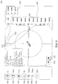
- FIG. 8 the Security Patrol Interface (or Safety Surveillance/Monitoring Interface) of the portable marine beacon system according to the invention is illustrated.
- This interface has the following functions: (1) monitor the ID/location/status of all transmitters on a real-time basis; (2) in the event of hazard, automatically trigger an audible alarm and an alert notification 850 on the screen.
- Each alert notification has four types of alerts, as shown in FIG. 8 , including precautionary alerts for safety protection : (2a) human-vessel impact (collision) alert; (2b) loss of signal (over time) alert; (2c) out of safe zone (over distance) alert; and (2d) DISTRESS (SOS) alert 840.
- Reference numeral 860 indicates the coordinates of a vessel, i.e. the coordinates of the smart device 230.
- the vessel is located at the center of the radar chart.
- Each icon(circle or star shape) indicates ID/location/status data of a person (transmitter).
- the upward pointing arrow 833 indicates the exit point (out of the water) of a dive group.
- the downward pointing arrow 834 indicates the entry point (into the water) of a dive group.
- the precautionary alert for collision 810 in (2a) is used to provide a collision warning on the monitoring screen and an audible alarm with respect to any transmitter data detected inside a hazardous zone with risk of collision between human and vessel.
- Reference numeral 811 represents the area of the hazardous zone. This hazardous zone includes a sector of 135° ahead of the vessel (receiver) with a radius 1 kilometer and a circular area with a radius 500-meter within which the vessel is located. If a person (transmitter), such as Jim 812, is detected to be located within this hazardous zone, the alert is triggered. When this alert is triggered, the icon of person and alert 810 shown on the screen will blink together with an audible alarm.
- the loss of signal (over time) alert 820 in (2b) is triggered if a person (transmitter), for example Joe 821, does not send data by the end of the planned exit time, the alert 820 and the icon(last coordinates) of Joe will blink together with an audible alarm.
- the over distance alert 830 (2c) is triggered if a person (transmitter), for example Lee 831, is located outside a safe zone, the alert 830 will blink together with an audible alarm and the icon of the person will be blinking.
- the circle zone 832 represents the safe zone for activity configured for a group of persons.
- the distress (SOS) alert 840 in (2d) is initiated by a transmitter 841 (person 012).
- the alert 840 will blink together with an audible alarm and the original icon of the person issuing the distress call will be replaced by a red star.
- DISTRESS Status is triggered, only swapping between DISTRESS status and DISTRESS TERMINATING status is allowed.
- the transmitter will automatically issue a distress terminating notification which will be shown on the screen as a green star 842 (persons 010, 017) continuously for one hour, allowing the neighboring ships to know that the person has been rescued to avoid futile rescue.
- the left-side pull-down function menu includes: 891: Tx/Redirect to the Transmitter Management Interface, 892: Plan/Redirect to the Activity planning Interface (or Alert Setting Interface); 893:Surv/Redirect to the Security Patrol Interface (or Safety Surveillance/Monitoring Interface); 894: Center/Mark the coordinates of the vessel at the center of the screen; 895: PB/Redirect to the Record Playback Interface (or History Playback Interface); and 896: Help/Get help from users guide.
- this interface has the functions to replay/share/delete recorded historical data of all transmitters in entire activity.
- the user first selects the date 930 from the right-side pull-down function menu and then selects the recorded data 910 of the person 940, Sam. Sam's coordinates will then be shown on the screen.
- the backward/forward buttons 920 and 921 can be clicked to show the previous/next data.
- the left-side pull-down function menu includes: 991: Tx/Redirect to the Transmitter Management Interface, 992: Plan/Redirect to the Activity Planning Interface (or Alert Setting Interface); 993: Surv/Redirect to the Security Patrol Interface (or Safety Surveillance/Monitoring Interface); 994: PB/Redirect to the Record Playback Interface (or History Playback Interface); 995: Center/Mark the coordinates of the vessel at the center of the screen; 996: Share/share or delete the recorded historical data; and 996: Help/Get help for operations.
- the transceiver can attain high-level hermeticity and waterproof by means of the following special designs:
- the transceiver of the invention is resistant to a underwater pressure up to 13 Bar, and in turn is suitable for technical diver at a depth of 120 meters or more.
- the portable marine beacon system invention can integrate a receiver and a transmitter into a single transceiver to simplify the manufacturing process and enhance the yield. Also, the invention can simplify the certification process and lower the certification cost in various countries and increase the flexibility for use.
- the present invention can attain effects that can not be attained by the prior art.
- the present invention complies with the stipulations of the Patent Act and possesses a high level or practicality.
Landscapes
- Engineering & Computer Science (AREA)
- Physics & Mathematics (AREA)
- General Physics & Mathematics (AREA)
- Computer Networks & Wireless Communication (AREA)
- Business, Economics & Management (AREA)
- Health & Medical Sciences (AREA)
- Emergency Management (AREA)
- Signal Processing (AREA)
- General Health & Medical Sciences (AREA)
- Radar, Positioning & Navigation (AREA)
- Child & Adolescent Psychology (AREA)
- Remote Sensing (AREA)
- Power Engineering (AREA)
- Public Health (AREA)
- Environmental & Geological Engineering (AREA)
- Alarm Systems (AREA)
- Mobile Radio Communication Systems (AREA)
- Emergency Alarm Devices (AREA)
- Position Fixing By Use Of Radio Waves (AREA)
- Traffic Control Systems (AREA)
Applications Claiming Priority (1)
| Application Number | Priority Date | Filing Date | Title |
|---|---|---|---|
| PCT/CN2017/108847 WO2019084831A1 (zh) | 2017-11-01 | 2017-11-01 | 一种可携式海上示标器系统 |
Publications (2)
| Publication Number | Publication Date |
|---|---|
| EP3706445A1 true EP3706445A1 (de) | 2020-09-09 |
| EP3706445A4 EP3706445A4 (de) | 2021-12-15 |
Family
ID=66333405
Family Applications (1)
| Application Number | Title | Priority Date | Filing Date |
|---|---|---|---|
| EP17930438.1A Pending EP3706445A4 (de) | 2017-11-01 | 2017-11-01 | Tragbares marines bakensystem |
Country Status (7)
| Country | Link |
|---|---|
| US (1) | US10861313B2 (de) |
| EP (1) | EP3706445A4 (de) |
| CN (1) | CN111386713B (de) |
| AU (1) | AU2017437901B2 (de) |
| MY (1) | MY199782A (de) |
| PH (1) | PH12020550502B1 (de) |
| WO (1) | WO2019084831A1 (de) |
Families Citing this family (7)
| Publication number | Priority date | Publication date | Assignee | Title |
|---|---|---|---|---|
| US11763111B2 (en) * | 2018-05-04 | 2023-09-19 | Rowan Companies, Inc. | System and method for locating personnel at muster station on offshore unit |
| CN113726705B (zh) * | 2021-11-03 | 2022-01-07 | 天津七一二移动通信有限公司 | 具有集成ais编解码能力的pdt对讲机 |
| USD1096991S1 (en) * | 2023-09-01 | 2025-10-07 | Quansheng Electronics Co., Ltd. | Walkie talkie |
| CN119152646A (zh) * | 2024-11-12 | 2024-12-17 | 中国海洋大学 | 一种浮标定位监测预警系统 |
| USD1122360S1 (en) * | 2025-03-06 | 2026-04-14 | Qiqi ZHANG | Toy walkie-talkie |
| USD1122361S1 (en) * | 2025-03-07 | 2026-04-14 | Qiqi ZHANG | Toy walkie-talkie |
| USD1090723S1 (en) * | 2025-03-10 | 2025-08-26 | Qiqi ZHANG | Toy walkie-talkie |
Family Cites Families (20)
| Publication number | Priority date | Publication date | Assignee | Title |
|---|---|---|---|---|
| US4305143A (en) * | 1979-08-08 | 1981-12-08 | Simms Larry L | Automatic man overboard sensor and rescue system |
| US6057759A (en) * | 1996-10-22 | 2000-05-02 | Marsh; Matthew T. | Marine personnel monitoring, overboard detection, alert and rescue system |
| US5886635A (en) * | 1997-07-29 | 1999-03-23 | Briartek, Inc. | Overboard alarm with localization system interface |
| US6222484B1 (en) * | 1999-06-16 | 2001-04-24 | Ronald L. Seiple | Personal emergency location system |
| FR2881837B1 (fr) * | 2005-02-10 | 2007-04-06 | Stephane Leal | Dispositif de signalisation et de localisation d'un individu a la mer et procede pour sa mise en oeuvre |
| CN101770009B (zh) * | 2009-01-06 | 2014-05-21 | 成都西谷曙光数字技术有限公司 | 一种精确射频定位系统 |
| FR2952747B1 (fr) * | 2009-11-13 | 2012-01-20 | Architecture Et Conception De Systemes Avances | Procede et dispositif de collecte a distance de donnees d'enregistreurs d'aeronefs ou de navires |
| US20120105247A1 (en) * | 2010-11-03 | 2012-05-03 | Yat Wai Edwin Kwong | Blackbox position reporting device |
| CN202035146U (zh) * | 2011-03-30 | 2011-11-09 | 上海太极电子科技发展有限公司 | 手持式ais终端机 |
| CN102426655B (zh) * | 2011-11-12 | 2013-09-11 | 成都雷电微力科技有限公司 | 集成有gps模块的rfid读写器芯片 |
| US9232378B2 (en) * | 2012-07-03 | 2016-01-05 | Qualcomm Incorporated | Locating a victim via a first responder's device |
| CN103199883B (zh) * | 2013-02-26 | 2015-05-13 | 中国科学院自动化研究所北仑科学艺术实验中心 | 嵌入式搜救海图仪及其控制方法 |
| US20140266793A1 (en) * | 2013-03-12 | 2014-09-18 | Nicholas F. Velado | Nautic alert apparatus, system, and method |
| US20140323079A1 (en) * | 2013-04-30 | 2014-10-30 | Paul S. Paolini | Personal locator device |
| EP3092867A4 (de) * | 2014-01-09 | 2017-07-19 | Oceaneering International Inc. | Drahtlose datenkommunikation zwischen einem ferngesteuerten fahrzeug und einem entfernten standort |
| CA2887443A1 (en) * | 2014-03-31 | 2015-09-30 | AWARE 360 Ltd. | Systems and methods for communication across multiple communications networks |
| US20160159446A1 (en) * | 2014-12-04 | 2016-06-09 | Anthony W. Covelli | Emergency beacon |
| CN205121919U (zh) * | 2015-11-10 | 2016-03-30 | 广州嘉航通信科技有限公司 | 一种无线ais船用设备及系统 |
| US10297158B2 (en) * | 2016-04-26 | 2019-05-21 | Clarksons Cloud Limited | Apparatus for monitoring emergency response vessel position |
| CN106792547B (zh) * | 2017-01-17 | 2020-11-27 | 北京小米移动软件有限公司 | 无人机呼救方法、装置、系统及无人机 |
-
2017
- 2017-11-01 US US16/758,432 patent/US10861313B2/en active Active
- 2017-11-01 WO PCT/CN2017/108847 patent/WO2019084831A1/zh not_active Ceased
- 2017-11-01 PH PH1/2020/550502A patent/PH12020550502B1/en unknown
- 2017-11-01 CN CN201780096365.0A patent/CN111386713B/zh active Active
- 2017-11-01 AU AU2017437901A patent/AU2017437901B2/en active Active
- 2017-11-01 EP EP17930438.1A patent/EP3706445A4/de active Pending
- 2017-11-01 MY MYPI2020002040A patent/MY199782A/en unknown
Also Published As
| Publication number | Publication date |
|---|---|
| US10861313B2 (en) | 2020-12-08 |
| WO2019084831A1 (zh) | 2019-05-09 |
| AU2017437901A1 (en) | 2020-05-14 |
| CN111386713B (zh) | 2022-06-10 |
| MY199782A (en) | 2023-11-23 |
| US20200320842A1 (en) | 2020-10-08 |
| AU2017437901B2 (en) | 2020-11-19 |
| CN111386713A (zh) | 2020-07-07 |
| PH12020550502A1 (en) | 2021-03-22 |
| PH12020550502B1 (en) | 2024-04-24 |
| EP3706445A4 (de) | 2021-12-15 |
Similar Documents
| Publication | Publication Date | Title |
|---|---|---|
| US10861313B2 (en) | Portable marine beacon system | |
| US7053822B2 (en) | Wearable satellite tracker | |
| US10583903B2 (en) | Underwater positioning system for scuba divers | |
| KR102149203B1 (ko) | 해상 조난위치 자동 발신 장치 | |
| US11830337B2 (en) | Signal device for maritime distress rescue and surveilance device for maritime distress rescue | |
| US20100026571A1 (en) | Nautical Safety Beacon | |
| US11294074B2 (en) | Tracking system and method | |
| CN102109595A (zh) | 利用个人定位终端的搜救系统及搜救方法 | |
| US20060196499A1 (en) | Scuba diver surface location, navigational and communication device and method | |
| KR20090101050A (ko) | 선박충돌방지장치 | |
| CN204319548U (zh) | 空气呼吸器的多功能告警安全设备 | |
| KR101389452B1 (ko) | 부유식 구명동의 위치추적장치 | |
| KR102458798B1 (ko) | 자율해상무선기기를 이용한 익수자 수색 구조 시스템 | |
| US20210312782A1 (en) | Man location and man overboard detection system | |
| US7612686B1 (en) | Emergency underwater notification device | |
| KR20140115684A (ko) | 선박용 융합형 선박위치 자동 발신시스템 | |
| KR20160104498A (ko) | Gps장착 구명조끼 및 스마트폰을 이용한 해난방지 안전 시스템 | |
| TWI636438B (zh) | Portable marine indicator system | |
| KR102716249B1 (ko) | 익수자 수색구조 시스템 | |
| CN206323382U (zh) | 水上防盗跟踪装置 | |
| CN220190873U (zh) | 一种可视楼宇安防对讲装置及设备 | |
| CN109805525A (zh) | 一种智能船员跟踪定位手环 | |
| EP2721591B1 (de) | Vorrichtung zum schutz vor elektronischem diebstahl/vandalismus mit sofortiger signalisierungs- und positionierungsreaktion | |
| KR20100138476A (ko) | 응급구조신호 발신 기능이 구비된 모자 | |
| KR20260015357A (ko) | Gps와 자이로센서를 활용한 자율주행 구명조끼 |
Legal Events
| Date | Code | Title | Description |
|---|---|---|---|
| STAA | Information on the status of an ep patent application or granted ep patent |
Free format text: STATUS: THE INTERNATIONAL PUBLICATION HAS BEEN MADE |
|
| PUAI | Public reference made under article 153(3) epc to a published international application that has entered the european phase |
Free format text: ORIGINAL CODE: 0009012 |
|
| STAA | Information on the status of an ep patent application or granted ep patent |
Free format text: STATUS: REQUEST FOR EXAMINATION WAS MADE |
|
| 17P | Request for examination filed |
Effective date: 20200523 |
|
| AK | Designated contracting states |
Kind code of ref document: A1 Designated state(s): AL AT BE BG CH CY CZ DE DK EE ES FI FR GB GR HR HU IE IS IT LI LT LU LV MC MK MT NL NO PL PT RO RS SE SI SK SM TR |
|
| AX | Request for extension of the european patent |
Extension state: BA ME |
|
| DAV | Request for validation of the european patent (deleted) | ||
| DAX | Request for extension of the european patent (deleted) | ||
| A4 | Supplementary search report drawn up and despatched |
Effective date: 20211115 |
|
| RIC1 | Information provided on ipc code assigned before grant |
Ipc: G01S 19/17 20100101ALI20211109BHEP Ipc: H04W 4/30 20180101ALI20211109BHEP Ipc: G01S 19/14 20100101ALI20211109BHEP Ipc: H04W 4/02 20180101AFI20211109BHEP |
|
| STAA | Information on the status of an ep patent application or granted ep patent |
Free format text: STATUS: EXAMINATION IS IN PROGRESS |
|
| 17Q | First examination report despatched |
Effective date: 20240214 |
|
| GRAP | Despatch of communication of intention to grant a patent |
Free format text: ORIGINAL CODE: EPIDOSNIGR1 |
|
| STAA | Information on the status of an ep patent application or granted ep patent |
Free format text: STATUS: GRANT OF PATENT IS INTENDED |
|
| RIC1 | Information provided on ipc code assigned before grant |
Ipc: G08B 21/02 20060101ALI20251128BHEP Ipc: H04W 4/029 20180101ALI20251128BHEP Ipc: H04W 84/12 20090101ALI20251128BHEP Ipc: H04W 4/02 20180101AFI20251128BHEP Ipc: G01S 19/14 20100101ALI20251128BHEP Ipc: H04W 4/30 20180101ALI20251128BHEP Ipc: G01S 19/17 20100101ALI20251128BHEP Ipc: G08B 5/00 20060101ALI20251128BHEP |
|
| INTG | Intention to grant announced |
Effective date: 20251211 |
|
| GRAS | Grant fee paid |
Free format text: ORIGINAL CODE: EPIDOSNIGR3 |
|
| GRAA | (expected) grant |
Free format text: ORIGINAL CODE: 0009210 |
|
| STAA | Information on the status of an ep patent application or granted ep patent |
Free format text: STATUS: THE PATENT HAS BEEN GRANTED |