EP3707318B1 - Structure de toit insonorisante d'un atelier présentant une durée de réverbération réduite - Google Patents
Structure de toit insonorisante d'un atelier présentant une durée de réverbération réduite Download PDFInfo
- Publication number
- EP3707318B1 EP3707318B1 EP18807883.6A EP18807883A EP3707318B1 EP 3707318 B1 EP3707318 B1 EP 3707318B1 EP 18807883 A EP18807883 A EP 18807883A EP 3707318 B1 EP3707318 B1 EP 3707318B1
- Authority
- EP
- European Patent Office
- Prior art keywords
- sound
- roof
- absorber
- absorbing
- hall
- Prior art date
- Legal status (The legal status is an assumption and is not a legal conclusion. Google has not performed a legal analysis and makes no representation as to the accuracy of the status listed.)
- Active
Links
Images


Classifications
-
- E—FIXED CONSTRUCTIONS
- E04—BUILDING
- E04B—GENERAL BUILDING CONSTRUCTIONS; WALLS, e.g. PARTITIONS; ROOFS; FLOORS; CEILINGS; INSULATION OR OTHER PROTECTION OF BUILDINGS
- E04B1/00—Constructions in general; Structures which are not restricted either to walls, e.g. partitions, or floors or ceilings or roofs
- E04B1/62—Insulation or other protection; Elements or use of specified material therefor
- E04B1/74—Heat, sound or noise insulation, absorption, or reflection; Other building methods affording favourable thermal or acoustical conditions, e.g. accumulating of heat within walls
- E04B1/82—Heat, sound or noise insulation, absorption, or reflection; Other building methods affording favourable thermal or acoustical conditions, e.g. accumulating of heat within walls specifically with respect to sound only
- E04B1/84—Sound-absorbing elements
- E04B1/86—Sound-absorbing elements slab-shaped
-
- E—FIXED CONSTRUCTIONS
- E04—BUILDING
- E04B—GENERAL BUILDING CONSTRUCTIONS; WALLS, e.g. PARTITIONS; ROOFS; FLOORS; CEILINGS; INSULATION OR OTHER PROTECTION OF BUILDINGS
- E04B7/00—Roofs; Roof construction with regard to insulation
- E04B7/02—Roofs; Roof construction with regard to insulation with plane sloping surfaces, e.g. saddle roofs
- E04B7/022—Roofs; Roof construction with regard to insulation with plane sloping surfaces, e.g. saddle roofs consisting of a plurality of parallel similar trusses or portal frames
-
- E—FIXED CONSTRUCTIONS
- E04—BUILDING
- E04B—GENERAL BUILDING CONSTRUCTIONS; WALLS, e.g. PARTITIONS; ROOFS; FLOORS; CEILINGS; INSULATION OR OTHER PROTECTION OF BUILDINGS
- E04B7/00—Roofs; Roof construction with regard to insulation
- E04B7/02—Roofs; Roof construction with regard to insulation with plane sloping surfaces, e.g. saddle roofs
- E04B7/04—Roofs; Roof construction with regard to insulation with plane sloping surfaces, e.g. saddle roofs supported by horizontal beams or the equivalent resting on the walls
-
- E—FIXED CONSTRUCTIONS
- E04—BUILDING
- E04C—STRUCTURAL ELEMENTS; BUILDING MATERIALS
- E04C3/00—Structural elongated elements designed for load-supporting
- E04C3/02—Joists; Girders, trusses, or trusslike structures, e.g. prefabricated; Lintels; Transoms; Braces
- E04C3/29—Joists; Girders, trusses, or trusslike structures, e.g. prefabricated; Lintels; Transoms; Braces built-up from parts of different material, i.e. composite structures
-
- G—PHYSICS
- G10—MUSICAL INSTRUMENTS; ACOUSTICS
- G10K—SOUND-PRODUCING DEVICES; METHODS OR DEVICES FOR PROTECTING AGAINST, OR FOR DAMPING, NOISE OR OTHER ACOUSTIC WAVES IN GENERAL; ACOUSTICS NOT OTHERWISE PROVIDED FOR
- G10K11/00—Methods or devices for transmitting, conducting or directing sound in general; Methods or devices for protecting against, or for damping, noise or other acoustic waves in general
- G10K11/16—Methods or devices for protecting against, or for damping, noise or other acoustic waves in general
- G10K11/162—Selection of materials
-
- E—FIXED CONSTRUCTIONS
- E04—BUILDING
- E04B—GENERAL BUILDING CONSTRUCTIONS; WALLS, e.g. PARTITIONS; ROOFS; FLOORS; CEILINGS; INSULATION OR OTHER PROTECTION OF BUILDINGS
- E04B1/00—Constructions in general; Structures which are not restricted either to walls, e.g. partitions, or floors or ceilings or roofs
- E04B1/99—Room acoustics, i.e. forms of, or arrangements in, rooms for influencing or directing sound
-
- E—FIXED CONSTRUCTIONS
- E04—BUILDING
- E04B—GENERAL BUILDING CONSTRUCTIONS; WALLS, e.g. PARTITIONS; ROOFS; FLOORS; CEILINGS; INSULATION OR OTHER PROTECTION OF BUILDINGS
- E04B9/00—Ceilings; Construction of ceilings, e.g. false ceilings; Ceiling construction with regard to insulation
- E04B9/001—Ceilings; Construction of ceilings, e.g. false ceilings; Ceiling construction with regard to insulation characterised by provisions for heat or sound insulation
Definitions
- the present invention relates to a sound-absorbing roof construction of a hall as well as a sound absorber arrangement and a hall with reduced reverberation time, using sound absorber elements and sound-absorbing absorber strips made of such elements.
- Sound-absorbing elements for improving room acoustics i.e. for better speech intelligibility and for hearing protection, have been known for a long time.
- Acoustic ceilings made of plasterboard or fiberboard improve room acoustics, reduce reverberation and convert sound energy into heat.
- Acoustic wall coverings are also known, such as panels that are attached to the walls at different angles and sizes and serve as depth absorbers for absorbing low sound frequencies. For absorbing high sound frequencies, the use of perforated panels is common, which are attached at certain distances from the wall. Sound-absorbing and sound-insulating materials, such as foam or felt, are placed between the panels and the wall.
- the EN 10 2011 105 608 A1 shows a sound absorber arrangement in the form of an edge absorber for low frequencies.
- the arrangement includes trough-shaped, preferably cuboid-shaped containers with fibrous or porous absorption material inside, which have a sound-impermeable or sound-permeable casing.
- the containers are arranged in the corners or edges of a room on the wall or ceiling.
- the sound absorber arrangement is characterized by the fact that all sides facing the room are sound-impermeable. are designed. Only one side, which is arranged at an angle, preferably perpendicular to a wall or ceiling, is designed to be absorbent with a smaller surface area.
- the containers used must have a minimum size, for which a corresponding amount of space must be provided locally.
- a preferred design uses, for example, a 400 mm x 500 mm thick homogeneous fibrous absorber, which is arranged on the floor near the edge of the room.
- the EN 10 2015 109 808 A1 describes a sound-absorbing building element, in particular for outdoor use, comprising a sound-absorbing covering layer and sound absorbing elements embedded therein with an increased degree of absorption compared to the covering layer.
- the EP 2 868 826 A1 describes a reinforced concrete element on whose surface a partially exposed, sound-absorbing, at least partially open-cell foamed material is arranged. The reinforcement is partially enclosed by the foamed material.
- a ceiling element is also shown which has several absorber strips made of geopolymer. When the concrete element is used as a ceiling panel, the absorber strips used run lengthwise but not in the corner areas between the wall and ceiling.
- Sound absorber elements made of sintered expanded glass granulate are available on the market, such as those supplied by Liaver GmbH & Co. KG under the brand name Reapor.
- the DE 200 22 685 U1 describes an acoustically absorptive panel element for eliminating reflected sound in rooms, which can be designed as a suspended ceiling or a wall.
- the WO95/30804 A1 describes a sound absorption system for interior walls and ceilings. Sound-absorbing elements are attached to the ceiling and extend to the wall. An arrangement is also shown in which corresponding elements are arranged on both the ceiling and the wall.
- a sound absorber arrangement consisting of several sound absorber elements.
- Several sound absorber elements arranged in a row form one or more absorber strips, which extend at least in sections along an upper edge running between the wall and ceiling of the room.
- the DE 2 347 136 A a self-supporting roof element for buildings, which rests on a wall at both ends and is particularly suitable for halls.
- the roof element has horizontal profile chords that extend longitudinally and are arranged symmetrically in pairs with respect to a vertical plane of symmetry. The chords are connected by a truss construction.
- the inside of the surfaces spanned by the truss can be covered with a mat. Since the areas to be covered with insulation material extend at an obtuse angle to the horizontally running outer roof skin, the resulting insulated area is significantly larger than the projected area of the roof skin. This follows the common assumption that for effective insulation or isolation, large areas must be covered with insulation material, which also leads to high costs.
- the JP-H10 46699 shows a sound-absorbing roof construction according to the preamble of claim 1.
- the object of the present invention is therefore to provide an improved sound-absorbing roof construction and a sound absorber arrangement for larger halls (500 - 50,000 m 3 volume), especially industrial halls, based on the state of the art.
- the sound absorber arrangement used should not impair the original use of the hall, in particular it should not require any or only small wall areas.
- a large absorption effect should be achieved with little use of material, so that the costs, especially for subsequent The soundproofing equipment in the hall should remain low despite the large hall area and volume.
- a significant improvement in the hall acoustics should be achieved over a wide frequency range.
- the sound-absorbing roof construction should make it possible to achieve the desired absorption results in halls with an almost unlimited floor area.
- a sound-absorbing roof construction according to the appended claim 1 serves.
- the object is further achieved by a hall with a reduced reverberation time according to claim 12.
- the sound-absorbing roof construction according to the invention is a structural component of a hall with walls, several roof trusses resting on the walls at least at their ends and with a sound-reflecting roof covering supported by the roof trusses.
- Absorber strips composed of sound-absorbing elements are attached to the side surfaces of several or all roof trusses. Between adjacent roof trusses with the absorber strips, a sound-reflecting section of the roof covering extends with a width that is at least twice the average height of the roof trusses.
- the sound absorber arrangement comprises several sound absorber elements which are arranged in a hall with walls and a roof structure which closes off the hall at the top.
- the roof structure has several roof trusses resting on the walls and a roof covering supported by the roof trusses.
- absorber strips are arranged on both side surfaces of several or all roof trusses. which are made up of sound absorbing elements arranged in a row.
- the roof trusses are usually spaced apart by more than twice, preferably more than four times, their average height, so that the area taken up by the absorber strips is in any case smaller than the projected area of the roof covering.
- the inner side of the roof skin which is usually sound-hard and therefore acoustically highly reflective, acts intentionally as an additional reflection surface, which reflects the sound waves generated inside the hall to the absorber elements, so that they are dampened there or, if necessary, completely absorbed.
- the roof trusses can have different constructions. For the invention, it is only important that they have two Provide side surfaces on which the absorber strips can be arranged. As a rule, the adjacent roof trusses are spaced several meters apart, preferably 4-8 m, in particular around 5-6 m.
- the interior of the roof structure extends from the lower edge of the roof truss, which is usually formed by a lower chord, to the inside of the roof covering, which rests on an upper chord of the roof truss. Typically, the lower chord and upper chord run at an angle to each other, so that the side surfaces of the roof truss have a trapezoidal or triangular shape.
- the roof trusses have a height of between 300-1,500 mm for the applications relevant here.
- Roof trusses with parallel or almost parallel upper and lower chords are also referred to as girders or trusses.
- a beam-like or flat infill can be arranged between the upper and lower chords.
- the roof truss rests with its ends on the walls of the hall and can be additionally supported if the span is large.
- the absorber strips cover the side surfaces of the roof trusses essentially completely, possibly leaving the upper and lower chords free.
- the absorber strip preferably has a width in the range of 400 - 1500 mm and thus follows the height of the roof trusses.
- the absorber strips can be attached to the upper and lower chords using simple metal profiles, for example. Gluing or other attachment of the sound absorber panels is also possible.
- Additional absorber strips are used that run along the upper edge of the walls and/or between adjacent roof trusses perpendicular to the side surfaces of the roof trusses in the roof structure. These additional absorber strips cover only a small part of the roof covering between the roof trusses, in particular less than a quarter of the roof covering surface.
- a particularly preferred embodiment of the sound-absorbing roof construction or the sound absorber arrangement is characterized in that a reflection surface is arranged between the absorber strips opposite each other on the roof truss, which extends between the upper chord and the lower chord of the roof truss.
- This reflection surface can be an integral part of the roof truss or used as a separate component.
- the sound absorber elements have a thickness of 20-65 mm, particularly preferably about 25 mm. Furthermore, it is advantageous if the sound absorber elements have a length-specific flow resistance in the range 7-15, preferably 8-12, particularly preferably about 10 kPa*s/m 4 .
- the sound absorbing elements consist of a non-ductile foam, in particular of a glass-based, acoustically effective and diffusion-open foam, which comprises expanded glass granulate.
- the sound absorbing elements consist of expanded glass granulate with a grain size of 0.25 - 4 mm, whereby the granulate is sintered in plate form or is connected with added binding agent, and whereby the length-specific flow resistance is preferably in the range 9-11 kPa*s/m 4.
- the preferred length-specific flow resistance of the sound absorber element can be easily adjusted by the grain sizes used, i.e. the grain size distribution in the preferably plate-shaped sound absorber element and/or by the proportion of binding agent which is added to the expanding gas granulate during production.
- the material used for the absorber strip is suitable for damp rooms, frost-proof, non-flammable and very light. It can also be cut to size without any problems. Due to the low weight, there are no static problems with the roof trusses, as these are usually designed for installation loads of around 25-30 kg/m 2 .
- the sound absorber elements have a length-specific flow resistance in the range 7-15 kPa*s/m 4 , preferably 9-11 kPa*s/m 4 , whereby the flow resistance in the sound absorber elements should be as uniform as possible.
- the hall according to the invention with reduced reverberation time can serve different purposes, in particular as an industrial or workshop hall, sports hall or swimming pool hall. It has walls and a roof structure, whereby the roof structure comprises several roof trusses resting on the walls and a roof covering supported by the roof trusses.
- the previously described sound absorber arrangement is arranged on several or all of the roof trusses.
- a key advantage of the hall with reduced reverberation time created according to the invention is that a particularly high level of sound absorption can be achieved by arranging the absorber strip on the roof trusses. This high level of absorption is achieved, among other things, by the reflections of the sound waves that occur in this area on the inner roof skin.
- the sound absorber arrangement can be integrated into existing halls at a later date with little effort and requires only a small amount of installation space in the roof space that is usually unused. By arranging the absorber strip on the roof trusses, the areas and volumes available for other uses in the hall are not or only minimally restricted.
- the inventive use of sound absorber elements on the side surfaces of the roof trusses makes it possible for the first time to achieve very efficient sound absorption with only small volumes of sound absorbing material and the area occupied by the sound absorber arrangement in a wide frequency range.
- relatively thin sound absorber elements can be installed in the immediate vicinity of the acoustically highly reflective roof covering.
- the length-specific flow resistance is set in the stated range, e.g. by suitable selection of the grain size and the material composition of the sound absorber elements used.
- the sound absorber elements are particularly preferably made of expanded glass granulate with a grain size of 0.25 - 4 mm, whereby the granulate is sintered in plate form or is bonded with added binding agent.
- the invention thus also uses a combination of the aforementioned properties of the sound absorbing elements and their aforementioned arrangement in the hall.
- further absorber strips extend along the upper ends of the walls of the hall.
- reverberation times in the range of 0.6 - 1.3 s can be achieved in halls, which corresponds to the desired value in communication rooms.
- the sound absorber arrangement is particularly suitable for damping in the frequency range from 250 Hz to 4 kHz.
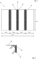
- Fig.1 shows a non-scale view of the ceiling underside of a hall 01 according to the invention with reduced reverberation time.
- the floor area of the hall extends, for example, to 21.5m x 17.5m.
- the hall is equipped with a sound absorber arrangement according to the invention, which is designed as a sound-absorbing roof construction.
- the hall 01 has walls 02 and three internal roof trusses 03, which form a roof skin 06 ( Fig.2 ).
- Absorber strips 04 are attached to the side surfaces of the roof trusses 03, which essentially cover the entire side surfaces.
- the roof trusses, which are covered with absorber strips on both sides, are spaced approximately 5.4 m apart in the example shown. There is approximately the same distance between the end walls and the next roof truss. Sections of the roof covering 06 extend between the roof trusses 03, which are sound-hard and whose width is more than twice the average height of the roof trusses.
- Each absorber strip 04 consists of one or preferably several sound absorbing elements made of a non-ductile foam, preferably a glass-based foam with an expanded glass granulate component. This material is well suited for sound insulation and is easy to process.
- the absorber strip has a width that is adapted to the height of the roof trusses and a thickness of, for example, 25 mm.
- the absorber strip 04 is preferably designed in the form of a plate. To form an absorber strip, several sound absorbing elements are lined up with little or no gaps between them. Small gaps between the sound absorbing elements only have a marginal effect on the acoustic damping result.
- Fig.2 shows in simplified form the absorber strip 04 arranged on the roof truss 03. It is clear that the roof covering 06 rests on the roof truss 03 and the absorber strip covers the side surface of the roof truss essentially over its entire height. The reflections of diffuse sound waves occurring on the roof covering 06 are shown in a highly simplified manner using arrows. The incident sound waves are reflected on the roof covering and directed into the absorber strip, whereby a particularly good absorption effect is achieved by means of the absorber strip 04.
- Fig.3 shows a non-scale view of the ceiling underside of a second embodiment of hall 01 with reduced reverberation time.
- the floor area of the hall is again 21.5m x 17.5m.
- further absorber strips 07 are attached to the upper ends of the end walls and on the side walls between the roof trusses.
- Fig.4 shows a simplified cross-sectional view of the roof truss 03, which has an upper chord 08, a lower chord 09 and a stiffening framework 10 between them.
- holding profiles 11 are attached to the roof truss to attach the absorber strips 04.
- the absorber strip is held between an upper and a lower holding profile 11, which are each attached to the upper and lower chords.
- an alternative to this is a holding profile 11 which is only attached to the upper chord 08 and yet still surrounds the absorber strip at its upper and lower edges.
- the retaining profile 11 has a sound-open rear side 13.
- a sound-reflecting reflection wall 12 which is positioned between the side surface of the roof truss and the absorber strip in order to reflect the sound waves penetrating the absorber strip back into the absorber strip.
- an air gap remains between the absorber strip and the reflection wall 12, which leads to further diffraction of the sound waves, which has a positive effect on the absorption due to interference and impedances that occur.
- Fig.5 shows two further design options for the arrangement of the absorber strips 04 on the roof truss 03. These variants are particularly suitable if the absorber strips are not attached to the roof trusses after the hall has been completed, but the sound-absorbing
- the roof trusses are equipped during the construction phase, preferably during the manufacture of the roof trusses.
- the absorber strips 04 are preferably integrated into the roof trusses 03.
- On the left side of the illustration in Fig.5 The absorber strip is inserted between the upper chord 08 and the lower chord 09, so that retaining profiles are not required.
- the absorber strip can be attached either to the supporting structure 10 and/or to the upper and lower chords.
- a first section of the absorber strip 04 is again arranged between the upper and lower chords, while further sections are attached to the double-T-shaped profiles of the upper and lower chords.
- the usable absorber surface is thus increased and the visual design is also improved.
- Fig.6 shows several measured curves for the reverberation time over a wide frequency range in a diagram.
- the individual curves were recorded in the same hall with a floor area of 21.5m x 17.5m and a height of 4.9m.
- Curve 1) - shown as a dash-dot line without marking - shows the course of the reverberation time in the original hall, i.e. without installation of the sound absorber arrangement.
- the reverberation time is on average 1.52 s and is therefore significantly higher than the value of 1.1 s required by DIN 18041 for speech environments (dashed line).
- Curve 2 shown as a solid line with square marking - shows the reverberation time after installation of the absorber strips according to the Fig.1 shown arrangement on the three interior roof trusses.
- the absorber strips have a width of 630 mm.
- the reverberation time decreases evenly across all frequencies to an average of 0.93 s.
- Curve 3) shown as a dashed line with diamond markings - shows the reverberation time in the hall if, in addition to the absorber strips on the roof trusses, further absorber strips with a width of 630 mm are installed around the side and front walls in accordance with the Fig.3 shown embodiment.
- the acoustic absorption performance is only slightly improved by the multiple installation.
- the reverberation time is 0.86 s.
- Curve 4) - shown as a solid line with a triangle marking - shows the reverberation time in the hall again according to the arrangement according to Fig.1 .
- Absorber strips are only located on the three interior roof trusses. However, the width of the absorber strips has been doubled to 1240 mm, while the thickness has remained the same. It turns out that in this way a significantly reduced reverberation time of 0.66 s can be achieved.
Landscapes
- Engineering & Computer Science (AREA)
- Architecture (AREA)
- Physics & Mathematics (AREA)
- Acoustics & Sound (AREA)
- Civil Engineering (AREA)
- Structural Engineering (AREA)
- Electromagnetism (AREA)
- Chemical & Material Sciences (AREA)
- Composite Materials (AREA)
- Multimedia (AREA)
- Building Environments (AREA)
Claims (12)
- Structure de toit insonorisante d'une halle (01), pourvue de parois (02), de plusieurs fermes (03) de toiture reposant au moins par leurs extrémités sur les parois (02) et d'une couverture (06) de toit portée par les fermes (03) de toiture,sur les surfaces latérales de plusieurs des fermes (03) de toiture étant montées des bandes d'absorption (04), lesquelles sont composées d'éléments absorbants acoustiques, entre des fermes (03) de toiture voisines pourvue des bandes d'absorption (04) s'étendant chaque fois une partie réfléchissante acoustique de la couverture (06) de toit qui présente une largeur qui s'élève au moins au double de la hauteur moyenne des fermes (03) de toiture et la couverture (06) de toit, qui s'étend entre les surfaces latérales des fermes (03) de toiture qui sont garnies avec les bandes d'absorption (04) n'étant pas recouverte de matière absorbante acoustique, caractérisée en ce quela couverture de toit comporte une face intérieure réverbérante et donc fortement réfléchissante acoustique, la face intérieure de la couverture de toit agissant en tant qu'une surface de réflexion additionnelle, laquelle réfléchit vers les éléments d'absorption les ondes acoustiques produites à l'intérieur de la halle.
- Structure de toit insonorisante selon la revendication 1, caractérisée en ce que les bandes d'absorption (04) recouvrent de manière sensiblement totale les surfaces latérales de toutes les fermes (03) de toiture situées dans l'espace intérieur de la halle (01).
- Structure de toit insonorisante selon la revendication 1 ou 2, caractérisée en ce que des bandes d'absorption (04) supplémentaires s'écoulent le long de l'arête supérieure des parois (02) et / ou entre des fermes (03) de toiture voisines dans la structure de toit.
- Structure de toit insonorisante selon l'une quelconque des revendications 1 à 3, caractérisée en ce qu'entre les bandes d'absorption (04) mutuellement opposées sur la même ferme (03) de toiture est placée une paroi de réflexion (12) acoustiquement dure qui s'étend entre la membrure supérieure (08) et la membrure inférieure (09) de la ferme (03).
- Structure de toit insonorisante selon la revendication 4, caractérisée en ce qu'entre les bandes d'absorption (04) et la paroi de réflexion (12) subsiste chaque fois un intervalle d'air.
- Structure de toit insonorisante selon l'une quelconque des revendications 1 à 5, caractérisée en ce que les éléments absorbants acoustiques des bandes d'absorption (04) ont une épaisseur de 20 à 65 mm, de préférence de 25 mm.
- Structure de toit insonorisante selon l'une quelconque des revendications 1 à 6, caractérisée en ce que les éléments absorbants acoustiques des bandes d'absorption (04) font preuve d'une résistance à l'écoulement spécifique à la longueur de l'ordre de 7 à 15 kPa*s/m4.
- Structure de toit insonorisante selon l'une quelconque des revendications 1 à 7, caractérisée en ce que les éléments absorbants acoustiques sont constitués d'une mousse non ductile, notamment d'une mousse à base de verre, laquelle comprend des granulés de verre soufflé.
- Structure de toit insonorisante selon la revendication 8, caractérisée en ce que les éléments absorbants acoustiques sont constitués de granulés de verre soufflé d'une granulométrie de von 0,25 à 4 mm, les granulés étant frittés en forme de plaque ou étant liés par un agent liant rajouté et la résistance à l'écoulement spécifique à la longueur se situant dans l'ordre de 9 à 11 kPa*s/m4.
- Structure de toit insonorisante selon l'une quelconque des revendications 1 à 9, caractérisée en ce que les fermes (03) de toiture sont écartées l'une de l'autre de plus du quadruple de leur hauteur moyenne.
- Structure de toit insonorisante selon l'une quelconque des revendications 1 à 10, caractérisée en ce que la surface occupée par les bandes d'absorption (04) sur les surfaces latérales des fermes (03) de toiture est inférieure à la surface projetée de la couverture (06) de toit.
- Halle (01) faisant preuve d'un temps de réverbération réduit, caractérisée en ce qu'elle comprend une structure de toit insonorisante selon l'une quelconque des revendications 1 à 11.
Applications Claiming Priority (2)
| Application Number | Priority Date | Filing Date | Title |
|---|---|---|---|
| DE102017126506.6A DE102017126506A1 (de) | 2017-11-11 | 2017-11-11 | Schallabsorberanordnung und Halle mit reduzierter Nachhallzeit |
| PCT/EP2018/080632 WO2019092115A1 (fr) | 2017-11-11 | 2018-11-08 | Structure de toit insonorisante d'un atelier présentant une durée de réverbération réduite |
Publications (3)
| Publication Number | Publication Date |
|---|---|
| EP3707318A1 EP3707318A1 (fr) | 2020-09-16 |
| EP3707318C0 EP3707318C0 (fr) | 2024-07-17 |
| EP3707318B1 true EP3707318B1 (fr) | 2024-07-17 |
Family
ID=64456932
Family Applications (1)
| Application Number | Title | Priority Date | Filing Date |
|---|---|---|---|
| EP18807883.6A Active EP3707318B1 (fr) | 2017-11-11 | 2018-11-08 | Structure de toit insonorisante d'un atelier présentant une durée de réverbération réduite |
Country Status (8)
| Country | Link |
|---|---|
| US (1) | US20200270860A1 (fr) |
| EP (1) | EP3707318B1 (fr) |
| JP (1) | JP2021502502A (fr) |
| CN (1) | CN111615575A (fr) |
| AU (1) | AU2018363745B2 (fr) |
| DE (1) | DE102017126506A1 (fr) |
| RU (1) | RU2769015C2 (fr) |
| WO (1) | WO2019092115A1 (fr) |
Citations (3)
| Publication number | Priority date | Publication date | Assignee | Title |
|---|---|---|---|---|
| DE2347136A1 (de) * | 1972-09-19 | 1974-03-28 | Yves Theault | Selbsttragendes dachelement fuer gebaeude sowie durch vereinigung mehrerer derartiger elemente erhaeltliches gebaeudedach |
| JPH1046699A (ja) * | 1996-08-05 | 1998-02-17 | Taisei Corp | 大空間における構造架構を利用した吸音構造 |
| US20080163565A1 (en) * | 2007-01-04 | 2008-07-10 | Murray Toas | Insulation batt with integral air vent |
Family Cites Families (23)
| Publication number | Priority date | Publication date | Assignee | Title |
|---|---|---|---|---|
| US3157251A (en) * | 1960-05-02 | 1964-11-17 | Nat Steel Corp | Building construction |
| JPS5444317A (en) * | 1977-09-13 | 1979-04-07 | Toyo Kankiyou Gijiyutsu Sentaa | Sound insulation building |
| JPS59112632U (ja) * | 1983-01-21 | 1984-07-30 | 日本鋼管株式会社 | 膜構造用吸音膜 |
| JP3105122B2 (ja) * | 1993-11-24 | 2000-10-30 | セントラル硝子株式会社 | 吸音性複合成形体およびその製法 |
| SE507187C2 (sv) | 1994-05-10 | 1998-04-20 | John Fellert | Ljudabsorptionssystem för innerväggar, innertak etc i byggnader samt förfarande för framställning av sådant ljudabsorptionssystem |
| DE29500435U1 (de) * | 1995-01-12 | 1995-03-02 | Construmat Ag, Hegnau-Volketswil | Dachkonstruktion sowie Dämmelement für eine solche Dachkonstruktion |
| US5623130A (en) * | 1995-11-20 | 1997-04-22 | Noxon; Arthur M. | System for enhancing room acoustics |
| JPH116201A (ja) * | 1997-04-23 | 1999-01-12 | Yasuyuki Okazaki | ドーム状構造物および排気ダクト |
| JPH10311105A (ja) * | 1997-05-12 | 1998-11-24 | Jutaku Toshi Seibi Kodan | 防音天井構造 |
| DE20022685U1 (de) | 2000-11-29 | 2002-01-17 | STO AG, 79780 Stühlingen | Akustisch absorptives Plattenelement |
| JP2004251002A (ja) * | 2003-02-20 | 2004-09-09 | Masakatsu Uchida | 重量鉄骨造による軽量建築物 |
| RU40637U1 (ru) * | 2004-04-20 | 2004-09-20 | Осипенков Александр Александрович | Устройство для защиты от акустических шумов жилых домов |
| US8733461B2 (en) * | 2006-06-27 | 2014-05-27 | Jeffrey Pigeon | Fire sprinkler system and method of installation |
| JP5069919B2 (ja) * | 2007-02-07 | 2012-11-07 | エムケー精工株式会社 | 消音装置 |
| WO2009125742A1 (fr) * | 2008-04-10 | 2009-10-15 | ブリヂストンケービージー株式会社 | Structure composite absorbant les sons |
| KR100916352B1 (ko) * | 2008-04-14 | 2009-09-11 | 주식회사 동진이엔지 | 발포콘크리트를 이용한 방음벽 |
| DE102008026650A1 (de) * | 2008-06-04 | 2009-12-24 | Lahnau Akustik Gmbh | Plattenelement |
| JP5581010B2 (ja) * | 2009-06-05 | 2014-08-27 | ブリヂストンケービージー株式会社 | 吸音パネル |
| DE102011105608B4 (de) | 2011-06-27 | 2020-02-27 | Forschungsgesellschaft für Systemsicherheit und Arbeitsmedizin e.V. (FSA e.V.) | Schall-Absorberanordnung für einen breiten Frequenzbereich mit einem Kanten-Absorber |
| EP2868826A1 (fr) | 2013-10-31 | 2015-05-06 | Basf Se | Élément de béton comprenant un absorbeur acoustique |
| CN104343206B (zh) * | 2014-11-04 | 2016-10-05 | 沈阿宝 | 一种消音龙骨 |
| DE102015109808A1 (de) | 2015-06-19 | 2016-12-22 | Liaver Gmbh & Co. Kg | Schallabsorbierendes Bauelement und Schallschutzwand mit einem solchen |
| CN206418644U (zh) * | 2017-01-06 | 2017-08-18 | 山东飞越钢结构工程有限公司 | 一种建筑设备屋顶 |
-
2017
- 2017-11-11 DE DE102017126506.6A patent/DE102017126506A1/de active Pending
-
2018
- 2018-11-08 AU AU2018363745A patent/AU2018363745B2/en active Active
- 2018-11-08 JP JP2020525987A patent/JP2021502502A/ja active Pending
- 2018-11-08 WO PCT/EP2018/080632 patent/WO2019092115A1/fr not_active Ceased
- 2018-11-08 EP EP18807883.6A patent/EP3707318B1/fr active Active
- 2018-11-08 RU RU2020118742A patent/RU2769015C2/ru active
- 2018-11-08 US US16/762,984 patent/US20200270860A1/en not_active Abandoned
- 2018-11-08 CN CN201880072877.8A patent/CN111615575A/zh active Pending
Patent Citations (3)
| Publication number | Priority date | Publication date | Assignee | Title |
|---|---|---|---|---|
| DE2347136A1 (de) * | 1972-09-19 | 1974-03-28 | Yves Theault | Selbsttragendes dachelement fuer gebaeude sowie durch vereinigung mehrerer derartiger elemente erhaeltliches gebaeudedach |
| JPH1046699A (ja) * | 1996-08-05 | 1998-02-17 | Taisei Corp | 大空間における構造架構を利用した吸音構造 |
| US20080163565A1 (en) * | 2007-01-04 | 2008-07-10 | Murray Toas | Insulation batt with integral air vent |
Also Published As
| Publication number | Publication date |
|---|---|
| DE102017126506A1 (de) | 2019-05-16 |
| RU2020118742A3 (fr) | 2022-01-26 |
| EP3707318A1 (fr) | 2020-09-16 |
| AU2018363745B2 (en) | 2024-05-02 |
| AU2018363745A1 (en) | 2020-06-04 |
| CN111615575A (zh) | 2020-09-01 |
| EP3707318C0 (fr) | 2024-07-17 |
| RU2020118742A (ru) | 2021-12-13 |
| RU2769015C2 (ru) | 2022-03-28 |
| WO2019092115A1 (fr) | 2019-05-16 |
| US20200270860A1 (en) | 2020-08-27 |
| JP2021502502A (ja) | 2021-01-28 |
Similar Documents
| Publication | Publication Date | Title |
|---|---|---|
| EP3532681B1 (fr) | Structure de plafond multifonctionnelle | |
| EP2072704A2 (fr) | Elément de cloison de séparation | |
| DE10214778A1 (de) | Schallabsorbierendes Paneel | |
| EP3455427B1 (fr) | Système d'absorption acoustique et pièce insonorisée | |
| EP2006462B1 (fr) | Plaque multicouche acoustique | |
| AT515271B1 (de) | Schalldämpfungselement | |
| DE4406878C2 (de) | Wandelelement | |
| EP3707318B1 (fr) | Structure de toit insonorisante d'un atelier présentant une durée de réverbération réduite | |
| EP3935624B1 (fr) | Absorbeur acoustique, structure et utilisation d'un absorbeur acoustique | |
| DE102014007660A1 (de) | Schallabsorptionsmittel, insbesondere zur Anordnung im Wand- und/oder Deckenbereich eines Raumes oder einer Halle zur Herstellung /Realisierung eines Raumteilers bzw. Schallabsorptionsvorrichtung bzw. Schalldämpfungslement | |
| EP2918745B1 (fr) | Couche de recouvrement composite pour élément absorbant le son | |
| EP3310965B1 (fr) | Élément de construction absorbant les sons et paroi insonorisante comprenant un tel élément | |
| DE69320393T2 (de) | Audio-Video Aufnahmeraum oder Konzertsaal | |
| WO2017198797A1 (fr) | Dispositif d'insonorisation et son procédé de production | |
| EP3555370B1 (fr) | Élément de construction absorbant le son à profilés d'étouffement et paroi d'insonorisation | |
| DE102010012202A1 (de) | Trennwandelement, insbesondere für eine mobile Trennwand, sowie entsprechende Trennwand | |
| DE102018002035A1 (de) | Gebäudewand-Modul und Gebäudewand mit Gebäudewand-Modulen | |
| EP3785256B1 (fr) | Élément extérieur d'isolation acoustique d'une façade d'un bâtiment | |
| DE3237062A1 (de) | Vorgefertigtes tafelelement mit einer mineralfaserplatte, sowie bauelementesatz fuer eine wandverkleidung mit solchen tafelelementen | |
| DE102012219223A1 (de) | Raumgliederungselement zur Schalldämmung bzw. Schallabsorption | |
| DE202023002953U1 (de) | Schlafkabine und Anordnung | |
| AT4079U1 (de) | Bauvorsatzschale mit feuerschutz-schallschutz-eigenschaften | |
| DE102013107363A1 (de) | Verfahren zum Aufbau eines Raumes und Raumbauteil | |
| DE202011002963U1 (de) | Absorbermodul und Rauminstallation | |
| DE202006014251U1 (de) | Schalldämmende Trennwand |
Legal Events
| Date | Code | Title | Description |
|---|---|---|---|
| STAA | Information on the status of an ep patent application or granted ep patent |
Free format text: STATUS: UNKNOWN |
|
| STAA | Information on the status of an ep patent application or granted ep patent |
Free format text: STATUS: THE INTERNATIONAL PUBLICATION HAS BEEN MADE |
|
| PUAI | Public reference made under article 153(3) epc to a published international application that has entered the european phase |
Free format text: ORIGINAL CODE: 0009012 |
|
| STAA | Information on the status of an ep patent application or granted ep patent |
Free format text: STATUS: REQUEST FOR EXAMINATION WAS MADE |
|
| 17P | Request for examination filed |
Effective date: 20200611 |
|
| AK | Designated contracting states |
Kind code of ref document: A1 Designated state(s): AL AT BE BG CH CY CZ DE DK EE ES FI FR GB GR HR HU IE IS IT LI LT LU LV MC MK MT NL NO PL PT RO RS SE SI SK SM TR |
|
| AX | Request for extension of the european patent |
Extension state: BA ME |
|
| DAV | Request for validation of the european patent (deleted) | ||
| DAX | Request for extension of the european patent (deleted) | ||
| STAA | Information on the status of an ep patent application or granted ep patent |
Free format text: STATUS: EXAMINATION IS IN PROGRESS |
|
| 17Q | First examination report despatched |
Effective date: 20220608 |
|
| GRAP | Despatch of communication of intention to grant a patent |
Free format text: ORIGINAL CODE: EPIDOSNIGR1 |
|
| STAA | Information on the status of an ep patent application or granted ep patent |
Free format text: STATUS: GRANT OF PATENT IS INTENDED |
|
| INTG | Intention to grant announced |
Effective date: 20240222 |
|
| GRAS | Grant fee paid |
Free format text: ORIGINAL CODE: EPIDOSNIGR3 |
|
| GRAA | (expected) grant |
Free format text: ORIGINAL CODE: 0009210 |
|
| STAA | Information on the status of an ep patent application or granted ep patent |
Free format text: STATUS: THE PATENT HAS BEEN GRANTED |
|
| AK | Designated contracting states |
Kind code of ref document: B1 Designated state(s): AL AT BE BG CH CY CZ DE DK EE ES FI FR GB GR HR HU IE IS IT LI LT LU LV MC MK MT NL NO PL PT RO RS SE SI SK SM TR |
|
| REG | Reference to a national code |
Ref country code: CH Ref legal event code: EP |
|
| REG | Reference to a national code |
Ref country code: DE Ref legal event code: R096 Ref document number: 502018014880 Country of ref document: DE |
|
| REG | Reference to a national code |
Ref country code: IE Ref legal event code: FG4D Free format text: LANGUAGE OF EP DOCUMENT: GERMAN |
|
| U01 | Request for unitary effect filed |
Effective date: 20240809 |
|
| U07 | Unitary effect registered |
Designated state(s): AT BE BG DE DK EE FI FR IT LT LU LV MT NL PT SE SI Effective date: 20240826 |
|
| U20 | Renewal fee for the european patent with unitary effect paid |
Year of fee payment: 7 Effective date: 20241014 |
|
| PG25 | Lapsed in a contracting state [announced via postgrant information from national office to epo] |
Ref country code: NO Free format text: LAPSE BECAUSE OF FAILURE TO SUBMIT A TRANSLATION OF THE DESCRIPTION OR TO PAY THE FEE WITHIN THE PRESCRIBED TIME-LIMIT Effective date: 20241017 |
|
| PG25 | Lapsed in a contracting state [announced via postgrant information from national office to epo] |
Ref country code: GR Free format text: LAPSE BECAUSE OF FAILURE TO SUBMIT A TRANSLATION OF THE DESCRIPTION OR TO PAY THE FEE WITHIN THE PRESCRIBED TIME-LIMIT Effective date: 20241018 Ref country code: PL Free format text: LAPSE BECAUSE OF FAILURE TO SUBMIT A TRANSLATION OF THE DESCRIPTION OR TO PAY THE FEE WITHIN THE PRESCRIBED TIME-LIMIT Effective date: 20240717 |
|
| PG25 | Lapsed in a contracting state [announced via postgrant information from national office to epo] |
Ref country code: IS Free format text: LAPSE BECAUSE OF FAILURE TO SUBMIT A TRANSLATION OF THE DESCRIPTION OR TO PAY THE FEE WITHIN THE PRESCRIBED TIME-LIMIT Effective date: 20241117 |
|
| PG25 | Lapsed in a contracting state [announced via postgrant information from national office to epo] |
Ref country code: HR Free format text: LAPSE BECAUSE OF FAILURE TO SUBMIT A TRANSLATION OF THE DESCRIPTION OR TO PAY THE FEE WITHIN THE PRESCRIBED TIME-LIMIT Effective date: 20240717 |
|
| PG25 | Lapsed in a contracting state [announced via postgrant information from national office to epo] |
Ref country code: ES Free format text: LAPSE BECAUSE OF FAILURE TO SUBMIT A TRANSLATION OF THE DESCRIPTION OR TO PAY THE FEE WITHIN THE PRESCRIBED TIME-LIMIT Effective date: 20240717 Ref country code: RS Free format text: LAPSE BECAUSE OF FAILURE TO SUBMIT A TRANSLATION OF THE DESCRIPTION OR TO PAY THE FEE WITHIN THE PRESCRIBED TIME-LIMIT Effective date: 20241017 |
|
| PG25 | Lapsed in a contracting state [announced via postgrant information from national office to epo] |
Ref country code: RS Free format text: LAPSE BECAUSE OF FAILURE TO SUBMIT A TRANSLATION OF THE DESCRIPTION OR TO PAY THE FEE WITHIN THE PRESCRIBED TIME-LIMIT Effective date: 20241017 Ref country code: PL Free format text: LAPSE BECAUSE OF FAILURE TO SUBMIT A TRANSLATION OF THE DESCRIPTION OR TO PAY THE FEE WITHIN THE PRESCRIBED TIME-LIMIT Effective date: 20240717 Ref country code: NO Free format text: LAPSE BECAUSE OF FAILURE TO SUBMIT A TRANSLATION OF THE DESCRIPTION OR TO PAY THE FEE WITHIN THE PRESCRIBED TIME-LIMIT Effective date: 20241017 Ref country code: IS Free format text: LAPSE BECAUSE OF FAILURE TO SUBMIT A TRANSLATION OF THE DESCRIPTION OR TO PAY THE FEE WITHIN THE PRESCRIBED TIME-LIMIT Effective date: 20241117 Ref country code: HR Free format text: LAPSE BECAUSE OF FAILURE TO SUBMIT A TRANSLATION OF THE DESCRIPTION OR TO PAY THE FEE WITHIN THE PRESCRIBED TIME-LIMIT Effective date: 20240717 Ref country code: GR Free format text: LAPSE BECAUSE OF FAILURE TO SUBMIT A TRANSLATION OF THE DESCRIPTION OR TO PAY THE FEE WITHIN THE PRESCRIBED TIME-LIMIT Effective date: 20241018 Ref country code: ES Free format text: LAPSE BECAUSE OF FAILURE TO SUBMIT A TRANSLATION OF THE DESCRIPTION OR TO PAY THE FEE WITHIN THE PRESCRIBED TIME-LIMIT Effective date: 20240717 |
|
| PG25 | Lapsed in a contracting state [announced via postgrant information from national office to epo] |
Ref country code: SM Free format text: LAPSE BECAUSE OF FAILURE TO SUBMIT A TRANSLATION OF THE DESCRIPTION OR TO PAY THE FEE WITHIN THE PRESCRIBED TIME-LIMIT Effective date: 20240717 |
|
| PG25 | Lapsed in a contracting state [announced via postgrant information from national office to epo] |
Ref country code: CZ Free format text: LAPSE BECAUSE OF FAILURE TO SUBMIT A TRANSLATION OF THE DESCRIPTION OR TO PAY THE FEE WITHIN THE PRESCRIBED TIME-LIMIT Effective date: 20240717 |
|
| PG25 | Lapsed in a contracting state [announced via postgrant information from national office to epo] |
Ref country code: SK Free format text: LAPSE BECAUSE OF FAILURE TO SUBMIT A TRANSLATION OF THE DESCRIPTION OR TO PAY THE FEE WITHIN THE PRESCRIBED TIME-LIMIT Effective date: 20240717 |
|
| PLBE | No opposition filed within time limit |
Free format text: ORIGINAL CODE: 0009261 |
|
| STAA | Information on the status of an ep patent application or granted ep patent |
Free format text: STATUS: NO OPPOSITION FILED WITHIN TIME LIMIT |
|
| 26N | No opposition filed |
Effective date: 20250422 |
|
| REG | Reference to a national code |
Ref country code: CH Ref legal event code: PL |
|
| PG25 | Lapsed in a contracting state [announced via postgrant information from national office to epo] |
Ref country code: MC Free format text: LAPSE BECAUSE OF FAILURE TO SUBMIT A TRANSLATION OF THE DESCRIPTION OR TO PAY THE FEE WITHIN THE PRESCRIBED TIME-LIMIT Effective date: 20240717 |
|
| REG | Reference to a national code |
Ref country code: CH Ref legal event code: PL |
|
| GBPC | Gb: european patent ceased through non-payment of renewal fee |
Effective date: 20241108 |
|
| PG25 | Lapsed in a contracting state [announced via postgrant information from national office to epo] |
Ref country code: CH Free format text: LAPSE BECAUSE OF NON-PAYMENT OF DUE FEES Effective date: 20241130 |
|
| PG25 | Lapsed in a contracting state [announced via postgrant information from national office to epo] |
Ref country code: GB Free format text: LAPSE BECAUSE OF NON-PAYMENT OF DUE FEES Effective date: 20241108 |
|
| PG25 | Lapsed in a contracting state [announced via postgrant information from national office to epo] |
Ref country code: IE Free format text: LAPSE BECAUSE OF NON-PAYMENT OF DUE FEES Effective date: 20241108 |
|
| U20 | Renewal fee for the european patent with unitary effect paid |
Year of fee payment: 8 Effective date: 20251016 |
|
| PG25 | Lapsed in a contracting state [announced via postgrant information from national office to epo] |
Ref country code: RO Free format text: LAPSE BECAUSE OF FAILURE TO SUBMIT A TRANSLATION OF THE DESCRIPTION OR TO PAY THE FEE WITHIN THE PRESCRIBED TIME-LIMIT Effective date: 20240717 |
|
| PG25 | Lapsed in a contracting state [announced via postgrant information from national office to epo] |
Ref country code: HU Free format text: LAPSE BECAUSE OF FAILURE TO SUBMIT A TRANSLATION OF THE DESCRIPTION OR TO PAY THE FEE WITHIN THE PRESCRIBED TIME-LIMIT; INVALID AB INITIO Effective date: 20181108 |
|
| PG25 | Lapsed in a contracting state [announced via postgrant information from national office to epo] |
Ref country code: CY Free format text: LAPSE BECAUSE OF FAILURE TO SUBMIT A TRANSLATION OF THE DESCRIPTION OR TO PAY THE FEE WITHIN THE PRESCRIBED TIME-LIMIT; INVALID AB INITIO Effective date: 20181108 |