EP3707337B1 - Einziehbare dach-/wandanordnung - Google Patents
Einziehbare dach-/wandanordnung Download PDFInfo
- Publication number
- EP3707337B1 EP3707337B1 EP18872046.0A EP18872046A EP3707337B1 EP 3707337 B1 EP3707337 B1 EP 3707337B1 EP 18872046 A EP18872046 A EP 18872046A EP 3707337 B1 EP3707337 B1 EP 3707337B1
- Authority
- EP
- European Patent Office
- Prior art keywords
- louvres
- gearbox
- track
- louvre
- wheels
- Prior art date
- Legal status (The legal status is an assumption and is not a legal conclusion. Google has not performed a legal analysis and makes no representation as to the accuracy of the status listed.)
- Active
Links
Images


Classifications
-
- E—FIXED CONSTRUCTIONS
- E04—BUILDING
- E04F—FINISHING WORK ON BUILDINGS, e.g. STAIRS, FLOORS
- E04F10/00—Sunshades, e.g. Florentine blinds or jalousies; Outside screens; Awnings or baldachins
- E04F10/08—Sunshades, e.g. Florentine blinds or jalousies; Outside screens; Awnings or baldachins of a plurality of similar rigid parts, e.g. slabs, lamellae
- E04F10/10—Sunshades, e.g. Florentine blinds or jalousies; Outside screens; Awnings or baldachins of a plurality of similar rigid parts, e.g. slabs, lamellae collapsible or extensible; metallic Florentine blinds; awnings with movable parts such as louvres
-
- E—FIXED CONSTRUCTIONS
- E06—DOORS, WINDOWS, SHUTTERS, OR ROLLER BLINDS IN GENERAL; LADDERS
- E06B—FIXED OR MOVABLE CLOSURES FOR OPENINGS IN BUILDINGS, VEHICLES, FENCES OR LIKE ENCLOSURES IN GENERAL, e.g. DOORS, WINDOWS, BLINDS, GATES
- E06B7/00—Special arrangements or measures in connection with doors or windows
- E06B7/02—Special arrangements or measures in connection with doors or windows for providing ventilation, e.g. through double windows; Arrangement of ventilation roses
- E06B7/08—Louvre doors, windows or grilles
- E06B7/082—Louvre doors, windows or grilles with rigid or slidable lamellae
-
- E—FIXED CONSTRUCTIONS
- E06—DOORS, WINDOWS, SHUTTERS, OR ROLLER BLINDS IN GENERAL; LADDERS
- E06B—FIXED OR MOVABLE CLOSURES FOR OPENINGS IN BUILDINGS, VEHICLES, FENCES OR LIKE ENCLOSURES IN GENERAL, e.g. DOORS, WINDOWS, BLINDS, GATES
- E06B7/00—Special arrangements or measures in connection with doors or windows
- E06B7/02—Special arrangements or measures in connection with doors or windows for providing ventilation, e.g. through double windows; Arrangement of ventilation roses
- E06B7/08—Louvre doors, windows or grilles
- E06B7/084—Louvre doors, windows or grilles with rotatable lamellae
- E06B7/086—Louvre doors, windows or grilles with rotatable lamellae interconnected for concurrent movement
- E06B7/096—Louvre doors, windows or grilles with rotatable lamellae interconnected for concurrent movement operated or interconnected by gearing
Definitions
- the present invention relates generally to architectural structures, such as roofs and walls, and in particular, to a retractable roof/wall structure comprising a plurality of louvres that are moveable and retractable to open/close and retract as desired.
- Modern architecture generally seeks to combine indoor and outdoor living in a way that maximises the enjoyment of sunshine and light but which also provides a degree of privacy and protection from the elements. It is the ability to provide a degree of control over the amount by which outdoor elements can be permitted into an indoor space which provides the most successful combination of such spaces.
- WO 2015/011263 A1 describes a architectural structure comprising retractable and moveable louvres comprising: a frame having a rear end, a front end and a pair of side walls connecting the front end and the rear end; a plurality of louvres extending substantially between the side walls, at least one end of the louvres being mounted to a gearbox member for controlling the angular orientation of the louvre, each gearbox member is mounted upon a track extending substantially along a length of at least one side wall and at least one of the gearbox members is mounted to a belt driven by a drive pulley; wherein, each gearbox member is attached to an adjacent gearbox member by way of a connector extending between adjacent gearbox members is constant such that when the louvres are in an extended position, the spacing between the louvres is maintained at a predetermined distance distance; the carrier mechanisms between the sliding elements are composed of a cable, the ends of which are fastened between each pair of successive sliding elements and which is long enough to be able to move the
- EP 3 315 686 A1 describes a sun protection installation comprising a system for moving the plurality of blackout slats comprising a rail and a guide each of which extends along a deployment direction of the plurality of blades and each one is attached to the transport frame, a plurality of carriages each comprising an element for hooking to the rail arranged to allow the movement of the carriage along the rail, an element for cooperation with the guide arranged to cooperate in translation with the guide in two opposite directions of deployment and a device for transmitting a rotary movement of the guide to the corresponding blade, being the rotary movement of the guide around the direction of extension on the guide and the rotary movement of the blade around the blade extension shaft.
- EP 2 730 714 A1 describes a composite covering structure for providing protection against sun and rain comprises a plurality of adjoining and overlapping swinging blades, coupled to a driving mechanism adapted, by a single operation, at first to cause the blades to gradually turn about their longitudinal axis, while being held in a same position, for providing a partial protection against sun, and then to cause said blades to slide on a horizontal plane, so as to compact said blades on a side, for uncovering the previously covered area.
- US 2015/152682 A1 describes a architectural cover for application to a roof or wall, comprising: A near end of the rectangle and a far end of the rectangle. Two spaced apart beams forming the left and right sides of the rectangle. A series of louvres spanning between the two beams. Wherein, the ends of each louvre are connected to a respective carriage. The carriages on one side are mounted to run to and fro along one of the beams, and the carriages on the other side are mounted to run to and fro along the other beam. A mechanism is provided to drive the distal carriage on each side to and fro to extend and retract the louvres.
- the connector is a belt and the pitch of the belt extending between adjacent gearboxes is controlled to maintain the spacing between louvres when in the extended position at a predetermined distance.
- Each gearbox member is mounted to the track so as to facilitate longitudinal movement of the gearbox along said track and rotational movement of the gearbox about the longitudinal axis of the track.
- the track is substantially circular in cross-section and each gearbox is mounted to the track by way of at least two opposing V-wheels which engage with the track.
- each gearbox may be mounted to the track by way of three V-wheels, two of the V-wheels being laterally disposed to engage with an upper surface of the track and one V-wheel engaging with a lower surface of the track.
- Each of the louvres may be mounted at one common end to an operational gearbox that is controllable to vary the angular orientation of the louvre and at the other end to an idler gearbox that supports the louvre and facilitates angular movement of the louvre under action of the operational gearbox.
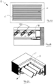
- FIG. 1 and 2 a roofing structure 10 and a wall structure 20 in accordance with an embodiment of the present invention is depicted.
- the roofing structure 10 comprises a rear support 12, in the form of a wall or the like and a pair of front supports 14, in the form of piers or pylons.
- a frame 16 is mounted to the rear support 12 along a rear end 16a thereof and has a pair of sides 16b, 16c extending orthogonally from opposing ends of the rear end 16a to be supported at their distal ends by the front supports 14.
- the frame 16 has an open front end 16d.
- the front end 16d may be closed by way of a front panel (not shown) that extends between the front supports 14.
- a plurality of louvres 15 are mounted within the frame 16 so as to be substantially parallel with the rear end 16a.
- each of the louvres 15 may be arranged between a retracted position and an extended position as shown in Fig. 1 by movement in the direction of arrow 'A'.
- Each of the individual louvres 15 may also be rotationally controlled about their central axis 'B' such that the angular position of the louvres may be altered to enable light to pass through the roofing structure 10.
- the angle of inclination of each louvre may vary depending upon the requirements of the user, with Fig. 1 depicting the louvres 15 in a closed configuration whereby they extend laterally to form a closed roofing structure. It will be appreciated that whilst the embodiment of Fig. 1 is mounted to a support wall, the frame 16 may be mounted on each of its ends by way of 4 columns or supports and does not need a rigid wall support.
- the wall structure 20 if Fig. 2 is similarly configured to the roofing structure 10 of Fig. 1 and similar reference numerals are used to represent similar features.
- the wall structure 20 comprises a main frame 16 having an upper rail 16a, a lower rail 16b, and an end support 16c.
- the individual louvres 15 are arranged to extend between the upper rail 16a and the lower rail 16b, and an end support (not shown) may be provided to support the end of the upper rail 16a.
- the louvres 15 may be moved between a retracted position and an extended position (as shown) in the direction of arrow 'A'.
- each louvre 15 is arranged to be rotational movable about its central axis 'B' so as to control the amount of light that may pass therethrough.
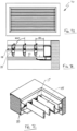
- a roofing structure 10 is depicted employing the louver system of the present invention.
- the frame 16 of the roofing structure has a rear end 16a, a front end 16d and a pair of sides 16b and 16c.
- the frame 16 defines an inner recess across which the louvres 15 extend.
- Fig. 4 is a cross sectional end view of the roofing structure 10, through line x-x of Fig. 3 .
- each of the louvres 15 extend from the rear end 16b to the front end 16a in a substantially parallel manner.
- the louvres 15 are in a closed configuration whereby they extend lengthwise across the recess in the roof to close the recess.
- Each of the sides, 16b and 16c are configured to comprise a substantially enclosed box 17 having a central slot 18 formed therein. The slot 18 enables the end of each louvre to be mounted to a mounting attachment provided on a gearbox housed within the box 17.
- each louvre 15 is mounted at each end to a gearbox that controls the angular position of the louvre 15, and each of the gearboxes are mounted within a retraction system located in the box 17 at each side 16b, 16c, which enables control of the position of the gearboxes and louvres 15, between an extended position and a retracted position.
- Figs 5A - 5C show the roofing structure 10 in the extended position, as depicted in Figs 3 and 4 .
- the retraction system is mounted within the boxes 17 functions to fully extend the louvres 15 such that the span the length of the recess in the roof.
- the gearboxes provided for each louvre are then controlled to maintain the louvres 15 in the horizontal position thereby extending across the recess in the roof to prevent light, rain, and the like from passing therethrough.
- Figs, 6A - 6C depict the roofing structure 10 in another state whereby the louvres 15 are extended to span the recess in the roof, but are rotated to extend at an angle to the horizontal, namely at a 135° angle for the embodiment as depicted.
- This state enables filtered light to pass through the roofing structure 10 to provide air flow and a degree of shade into the underlying space.
- the angular movement of each louvre is provided by controlling the gearboxes housed within the boxes 17 located at each side 16b, 16c of the structure and which are provided at each end of each louvre 15.
- As the louvres 15 are mounted to a mounting arm of each gearbox that extends out each slot 18, each louvre 15 is able to be rotated from each end thereof, sharing the load between each end.
- Figs. 7A - 7C depict the roofing structure 10 in yet another state, whereby the louvres 15 are extended to span the recess in the roof, but are rotated to extend vertically as shown.
- This state provides a more open roof structure 10 that enables more light and air to pass through the roofing structure 10 to provide a more outdoor feel to the underlying space.
- the angular movement of each louvre 15 is provided by controlling the gearboxes housed within the boxes 17 located at each side 16b, 16c of the structure and which are provided at each end of each louvre 15.
- the gearboxes housed within the boxes 17 located at each side 16b, 16c of the structure and which are provided at each end of each louvre 15.
- As the louvres 15 are mounted to a mounting arm of each gearbox that extends out each slot 18, each louvre 15 is able to be rotated from each end thereof, sharing the load between each end.
- Figs. 8A - 8C depict the roofing structure 10 in yet another state, whereby the louvres 15 are fully retracted against the rear side 16a of the structure. This is shown in Fig. 8A .
- each of the louvres 15 are firstly rotated to extend vertically with respect to the roofing structure 10 and the retraction system mounted within the boxes 17 on either side 16a, 16c of the structure is activated to retract the louvres towards the rear of the structure 10.
- system may be configured to retract the louvres 15 to the front of the structure if desired and in some instances, the system may be configured to retract half of the louvres to the front of the structure and the other half of the louvres to the rear of the structure as required. The manner in which this is achieved will be discussed in more detail below.
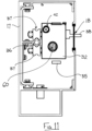
- the retraction system 30 is configured to be housed within box 17 and comprises a drive pulley 31 mounted at one end and an adjustable pulley assembly 33 at the other end.
- the adjustable pulley assembly 33 comprises an upper and lower pulley wheel 34 around which a drive belt 35 passes.
- the drive belt 35 extends the length of the box 17 and is in operational engagement with the drive pulley 31 in the manner as best depicted by Fig. 9 .
- the adjustable pulley assembly 33 is able to be laterally adjustable in position to facilitate fitting of the drive belt 35 and to ensure that any slack present in the drive belt 35 is removed.
- a track member 36 in the form of a circular tube, extends substantially the length of the box 17.
- a plurality of gearboxes 32 are mounted to travel along the track member 36 in the manner as shown in Fig. 11 .
- each gearbox 32 has a three V-wheels 37, namely a pair of upper V-wheels 37 mounted to a rear surface thereof and a vertically displaced lower V-wheel 37, as is more clearly shown in Fig. 13 .
- the V-wheels 37 are made from a plastic or similar material and are fitted about the track member so as to clamp about the track member 36 from an upper and lower position, as best depicted in Fig. 11 .
- each gearbox 32 is able to travel laterally along the track member 36 in a forward and rearward direction depending upon whether the louvres are to be in an extended or retracted position.
- the manner in which the gearboxes 32 are driven will be described in more detail below.
- the angle of orientation of the associated gearbox may change. If there is a degree of misalignment between the gearboxes 32 and the louvre, this can cause forces to build up within the gearbox 32 which can cause premature wear and failure of the gearboxes. However, as the V-wheels 37 engage about the track member 36 in a manner which allows a degree of rotation of the gearboxes 32 with respect to the track member 36, the gearboxes 32 can rotate to match the angle of the louvre which is governed by the angle of the length and fall of the louvre, thus minimising unwanted forces building up within the gearbox and maximising gearbox life.
- the track member 36 As the track member 36 is mounted within the structure, over time it will be exposed to dust and dirt collecting along the surface thereof. Due to the action of the V-Wheels 37 travelling along the track member 36 and being able to rotate in relation thereto, the V-wheels 37 are able to act as a self-cleaning mechanism that continually cleans the tracks and does not allow dirt and dust to build up, as is a common problem with most existing C-channel tracks employed for similar purposes.
- V-wheels 27 to engage with the track member 36, namely with two V-wheels located on the top and one V-wheel located underneath, enables the system to be simply adjusted to ensure that the engagement of the V-wheels with the track is snug. This can then prevent rotation of the gearboxes 32 and prevent any upward or downward movement of the louvres due to wing loading events and the like.
- each gearbox 32 is a low friction gearbox and is mounted to an end of a louvre 25 by way of the mounting member 38 that extends from a slot 18 in the box 17.
- the mounting member 38 is shown in Fig. 11 with the mounting member 38 being in the form of a flat pin member. It will be appreciated that the flat pin member 38 will engage with an end of the louvre 25 and each gearbox 32 is able to be controlled to rotate the mounting member 38, thereby causing the louvre to rotate in the same direction. This is achieved by an actuation carriage 60 being configured to extend through each gearbox 32 so as to operatively engage with the mounting member 38.
- the actuation carriage 60 is mounted at one end to an actuator 62 which is controlled to impart rotation to the actuation carriage 60 so as to control the state of the louvres 25.
- the actuator 62 is mounted towards one end of the box 17.
- the actuation carriage 60 is substantially square in cross section and is received within a square recess extending through each gearbox 32. Upon rotation of the actuation carriage 60, the rotation is transferred to the mounting member 38 of each gearbox thereby causing the associated louvres 25 to rotate in unison with each other. It will be appreciated that such gearboxes are well known in the art and will not be described in further detail.
- each gearbox 32 is a low friction gearbox, it requires very low torque to rotate each of the louvres 25 as provided by the actuation carriage 60.
- This allows the electrical control system of the actuator 62 to detect an amperage increase during opening/closing the louvres which is indicative of the presence of an obstacle between the louvres, such as a person's fingers or a body part, preventing louvre movement.
- the present system is able to cut/off the actuator 62 as a safety mechanism should the amperage reach a present level. It will be appreciated that if the gearbox friction is too high, a larger motor is required in the actuator 62 to rotate the multiple louvres.
- the present invention is configured to enable such detection due to the configuration of the gearboxes and the manner in which they are actuated.
- the low friction gearboxes 32 also enable a much smaller motor to be used in the actuator 62 to rotate the louvres.
- Fig. 12 The manner in which the gearboxes 32 are able to be extended and retracted is depicted in Fig. 12 .
- the leading gearbox 32 is attached to the drive belt 35 at the upper or lower end thereof, such that movement of the drive belt 35 under action of the drive pulley 31 will cause the leading gearbox 32 to move along the track member 36.
- Each gearbox along the line is connected by way of a timing belt 40 with the pitch of the timing belt extending between adjacent gearboxes 32 being the same.
- the use of such a timing belt 40 ensures that during the extension and retraction process, the timing belt 40 is bent in a consistent manner each time.
- the presence of teeth within the timing belt 40 ensures that the belt 40 always folds in the same direction to enable control over how the belt folds during the stacking process, which is repeatable time after time. If wire, string or rope is used, such materials fold or bend in an unpredictable manner and are prone to tangling, thus increasing the likelihood of the system becoming jammed or otherwise malfunctioning, and requiring costly intervention and ongoing servicing.
- the drive pulley 31 is merely reversed such that the leading gearbox 32 is caused to move back towards the drive pulley 31.
- the timing belt 40 slackens until the stopper 42 contacts the leading face of the trailing gearbox thereby pushing that gearbox 42 back towards the drive pulley 31.
- This creates a concertina effect thereby retracting the louvres and pushing the louvres 25 towards one end of the roofing structure. It will be appreciated that prior to retraction of the louvres, the gearboxes will cause the louvres to rotate into a vertical position to ensure maximum retraction.
- each gearbox 32 is connected to an end of a louvre 25 with the other end of the louvre 25 being connected to an idler carriage of an identical retraction system.
- the idler carriage also contains a timing belt 40 to set the pitch between idler carriages.
- the idler carriage also functions to accommodate any misalignment between the two carriages as the shaft of the idler carriage slides in and out of a simple housing. It will be appreciated that, in such an arrangement, both drive pulleys can be controlled in unison to provide a controlled louvre retraction and extension arrangement, with minimal likelihood of jamming of the louvres due to misalignment.
- the idler carriage has a free floating shaft that connects to the louvre.
- the louvres can be simply and effectively moved in to an abutting manner that provides a sealed and enclosed roofing structure.
- the ability to control both ends of the louvre movement in such a finite manner ensures that the louvres are continually moved in a controlled manner to minimise misalignment of louvres and potential leakages in the roof structure.
Landscapes
- Engineering & Computer Science (AREA)
- Civil Engineering (AREA)
- Structural Engineering (AREA)
- Architecture (AREA)
- Specific Sealing Or Ventilating Devices For Doors And Windows (AREA)
- Power-Operated Mechanisms For Wings (AREA)
Claims (4)
- Architektonische Struktur, umfassend:einen Rahmen (16), der ein hinteres Ende (16a), ein vorderes Ende (16d) und einem Paar Seitenwände (16b, 16c), die das vordere Ende mit dem hinteren Ende verbinden, aufweist;eine Vielzahl von Lamellen (15), die sich im Wesentlichen zwischen den Seitenwänden erstreckt, wobei mindestens ein Ende der Lamellen an einem Getriebeelement (32) montiert ist, um die Winkelausrichtung der Lamellen zu steuern, wobei jedes Getriebeelement auf einer Schiene (36) montiert ist, die sich im Wesentlichen entlang einer Länge mindestens einer Seitenwand erstreckt und mindestens eines der Getriebeelemente an einem Riemen (35) montiert ist, der durch eine Antriebsscheibe (31) angetrieben wird, um eine Längsbewegung des mindestens einen Getriebeelements entlang der Schiene sowie eine Drehbewegung des mindestens einen Getriebeelements um eine Längsachse der Schiene zu ermöglichen,wobei, jedes Getriebeelement über einen Verbinder an einem benachbarten Getriebeelement befestigt ist, wodurch eine Länge des Verbinders, der sich zwischen benachbarten Getriebeelementen erstreckt, konstant ist, sodass, wenn sich die Lamellen in einer ausgefahrenen Position befinden, die Beabstandung zwischen den Lamellen auf einem vorgegebenen Abstand gehalten wird,dadurch gekennzeichnet, dass die Schiene (36) einen im Wesentlichen kreisförmigen Querschnitt aufweist und jedes Getriebeelement (32) über mindestens zwei gegenüberliegende V-Räder (37), die mit der Schiene in Eingriff stehen, an der Schiene montiert ist.
- Architektonische Struktur nach Anspruch 1, wobei der Verbinder ein Riemen (40) ist und die Teilung des Riemens, der sich zwischen benachbarten Getrieben erstreckt, gesteuert wird, um die Beabstandung zwischen den Lamellen auf einem vorgegebenen Abstand zu halten, wenn sie in der ausgefahrenen Position befinden.
- Architektonische Struktur nach Anspruch 1, wobei die mindestens zwei gegenüberliegenden V-Räder (37) drei V-Räder umfassen, wobei zwei der drei V-Räder seitlich angeordnet sind, um mit einer oberen Fläche der Schiene in Eingriff zu treten, und eines der drei V-Räder mit einer unteren Fläche der Schiene in Eingriff steht.
- Architektonische Struktur nach Anspruch 1, wobei jede der Lamellen (15) an einem Ende an dem Getriebeelement montiert ist, das steuerbar ist, um die Winkelausrichtung der Lamelle zu variieren, und jede der Lamellen an einem gegenüberliegenden Ende an einem Zwischengetriebe montiert ist, das die Lamelle trägt und die Winkelbewegung der Lamelle unter Einwirkung des Getriebeelements ermöglicht.
Applications Claiming Priority (2)
| Application Number | Priority Date | Filing Date | Title |
|---|---|---|---|
| AU2017904402A AU2017904402A0 (en) | 2017-10-30 | Retractable roof/wall assembly | |
| PCT/AU2018/000211 WO2019084590A1 (en) | 2017-10-30 | 2018-10-30 | Retractable roof/wall assembly |
Publications (3)
| Publication Number | Publication Date |
|---|---|
| EP3707337A1 EP3707337A1 (de) | 2020-09-16 |
| EP3707337A4 EP3707337A4 (de) | 2021-10-27 |
| EP3707337B1 true EP3707337B1 (de) | 2023-10-11 |
Family
ID=66331150
Family Applications (1)
| Application Number | Title | Priority Date | Filing Date |
|---|---|---|---|
| EP18872046.0A Active EP3707337B1 (de) | 2017-10-30 | 2018-10-30 | Einziehbare dach-/wandanordnung |
Country Status (7)
| Country | Link |
|---|---|
| US (1) | US11313130B2 (de) |
| EP (1) | EP3707337B1 (de) |
| AU (1) | AU2018360615B2 (de) |
| ES (1) | ES2969932T3 (de) |
| NZ (1) | NZ764635A (de) |
| SG (1) | SG11202003958VA (de) |
| WO (1) | WO2019084590A1 (de) |
Cited By (1)
| Publication number | Priority date | Publication date | Assignee | Title |
|---|---|---|---|---|
| EP4592471A1 (de) | 2024-01-23 | 2025-07-30 | WAREMA Renkhoff SE | Sonnenschutzanlage mit antriebseinheit |
Families Citing this family (15)
| Publication number | Priority date | Publication date | Assignee | Title |
|---|---|---|---|---|
| CN108166688B (zh) | 2017-05-08 | 2019-11-05 | 宁波万汇休闲用品有限公司 | 遮蔽篷装置 |
| EP3495582A1 (de) | 2017-12-08 | 2019-06-12 | Activa Awning Inc. | Markisenvorrichtung |
| FR3093339B1 (fr) * | 2019-02-28 | 2021-03-05 | Biossun | Installation pour couvrir une surface à l’aide de lames orientables translatées à plat |
| US11486139B2 (en) * | 2020-04-23 | 2022-11-01 | Rostyslav Geriavenko | Louvered pergola |
| US11473311B1 (en) * | 2021-12-31 | 2022-10-18 | Renaissance Patio Products Inc. | Louver roof structure |
| EP3995643A1 (de) | 2020-11-04 | 2022-05-11 | Qingdao Activa Shade Inc. | Einziehbare schattenstrukturen |
| US11560718B1 (en) | 2021-12-31 | 2023-01-24 | Renaissance Patio Products Inc. | Louver roof structure |
| CN114016888B (zh) * | 2021-12-31 | 2022-04-08 | 佛山市磁家有导科技有限公司 | 一种可堆叠的翻转百叶格栅 |
| EP4234873B1 (de) * | 2022-02-25 | 2026-04-08 | Aluvision N.V. | Lamellenkontrolsystem |
| BE1030303B1 (nl) * | 2022-02-25 | 2023-09-25 | Aluvision N V | Lamellenregelsysteem |
| ES2952145A1 (es) | 2022-03-21 | 2023-10-27 | Codeval Aluminium Sl | Pérgola de lamas giratorias |
| GR1010520B (el) * | 2022-07-29 | 2023-08-10 | Θεοδωρος Νικολαου Κρητικιας | Ανοιγοκλειομενο σκεπαστρο |
| ES2978282B2 (es) | 2023-01-31 | 2025-04-10 | Codeval Aluminium Sl | Cierre de lamas plegable |
| CN116104264B (zh) * | 2023-02-17 | 2025-09-26 | 广东省水利水电第三工程局有限公司 | 一种用于弧形建筑的大悬挑、可伸缩钢框架雨棚 |
| USD1088275S1 (en) * | 2025-02-20 | 2025-08-12 | Zhejiang pioneer leisure products co., ltd | Gazebo canopy |
Family Cites Families (16)
| Publication number | Priority date | Publication date | Assignee | Title |
|---|---|---|---|---|
| US2135647A (en) * | 1938-05-12 | 1938-11-08 | Waldo M Streby | Window shade |
| US5291946A (en) * | 1993-02-05 | 1994-03-08 | Micro Molds Corp. | Carrier assembly for use in a vertical blind assembly |
| US5626177A (en) * | 1995-06-07 | 1997-05-06 | Hunter Douglas Inc. | Control and suspension system for a vertical vane covering for architectural openings |
| GB201007328D0 (en) * | 2010-05-04 | 2010-06-16 | Gray Matter Alpha Ltd | Lourve vane system |
| US9175511B2 (en) | 2011-07-29 | 2015-11-03 | Advanced Design Innovations Pty Limited | Retractable louvre system |
| ITMI20121911A1 (it) * | 2012-11-09 | 2014-05-10 | Frigerio Tende Da Sole S R L | Struttura di copertura a pale basculanti. |
| GB2511053B (en) * | 2013-02-20 | 2017-09-20 | Orangebox Ltd | A ceiling panel |
| BE1021987B1 (nl) | 2013-07-26 | 2016-02-02 | Brustor, Naamloze Vennootschap | Zonnescherm |
| WO2015130365A2 (en) | 2013-12-04 | 2015-09-03 | Urthecast Corp. | Systems and methods for earth observation |
| ITBA20140016U1 (it) * | 2014-07-04 | 2016-01-04 | Smarlite S R L | "meccanismo di impacchettamento e rotazione di lamelle orientabili atte a proteggere dai raggi solari, pioggia o altri agenti atmosferici" |
| FR3027334B1 (fr) * | 2014-10-15 | 2017-02-24 | Biossun | Installation pour couvrir et decouvrir une surface a l'aide de lames orientables automotrices |
| FR3049976B1 (fr) * | 2016-04-12 | 2022-08-05 | Biossun | Installation pour couvrir et decouvrir une surface a l'aide de lames orientables automotrices attelees |
| US10934770B2 (en) * | 2016-07-20 | 2021-03-02 | Navus Consulting Cc | Slat for a blind and blind formed therefrom |
| FR3058173B1 (fr) | 2016-10-31 | 2019-06-07 | Tir Technologies Toiles Industrielles Du Rhin Technologies | Installation de protection contre le soleil |
| US10094122B1 (en) * | 2017-06-06 | 2018-10-09 | Optimal Tasarim Uygulama Ve Yapi Sistemleri San. Ve Tic. Anomim Sirketi | Automatic wide angle panel roof |
| US10851544B1 (en) * | 2020-01-07 | 2020-12-01 | Dee Volin | Multi-function wind-directing leaf-separating-and-discharging rainwater-sealing automatic-multi-screen-raising-and-lowering multi-screen-securing fruit-drying-and-sorting truck-tonneau-covering rainwater-channeling-and-collecting leaf-filtering height-and-angle-adjustable louvered pergola |
-
2018
- 2018-10-30 NZ NZ764635A patent/NZ764635A/en unknown
- 2018-10-30 EP EP18872046.0A patent/EP3707337B1/de active Active
- 2018-10-30 AU AU2018360615A patent/AU2018360615B2/en active Active
- 2018-10-30 WO PCT/AU2018/000211 patent/WO2019084590A1/en not_active Ceased
- 2018-10-30 US US16/760,703 patent/US11313130B2/en active Active
- 2018-10-30 SG SG11202003958VA patent/SG11202003958VA/en unknown
- 2018-10-30 ES ES18872046T patent/ES2969932T3/es active Active
Cited By (1)
| Publication number | Priority date | Publication date | Assignee | Title |
|---|---|---|---|---|
| EP4592471A1 (de) | 2024-01-23 | 2025-07-30 | WAREMA Renkhoff SE | Sonnenschutzanlage mit antriebseinheit |
Also Published As
| Publication number | Publication date |
|---|---|
| WO2019084590A1 (en) | 2019-05-09 |
| SG11202003958VA (en) | 2020-05-28 |
| US11313130B2 (en) | 2022-04-26 |
| EP3707337A1 (de) | 2020-09-16 |
| NZ764635A (en) | 2025-12-19 |
| ES2969932T3 (es) | 2024-05-23 |
| AU2018360615B2 (en) | 2025-01-02 |
| US20200354962A1 (en) | 2020-11-12 |
| EP3707337A4 (de) | 2021-10-27 |
| AU2018360615A1 (en) | 2020-06-11 |
Similar Documents
| Publication | Publication Date | Title |
|---|---|---|
| EP3707337B1 (de) | Einziehbare dach-/wandanordnung | |
| US11015349B2 (en) | Apparatus for covering and uncovering a surface using coupled self-propelled adjustable slats | |
| EP3234273B1 (de) | Pergolaabdeckung | |
| EP3024997B1 (de) | Sonnenblende | |
| US10280625B2 (en) | Unit for covering and uncovering a surface using self-propelled adjustable slats | |
| US9175511B2 (en) | Retractable louvre system | |
| US8413705B2 (en) | Orientable panel of a roofing device | |
| US20220120088A1 (en) | Installation for covering a surface using orientatable blades that are translated flat | |
| EP4232653B1 (de) | Dachkonstruktion für ein terrassendach, bausatz zur montage der dachkonstruktion und terrassendach mit der dachkonstruktion | |
| JP2008261195A (ja) | 縦型ルーバー装置 | |
| JP5953983B2 (ja) | ブラインド装置 | |
| KR101803536B1 (ko) | 다목적 가변형 외부 차양장치 | |
| EP2896763B1 (de) | Ausfahrbare, schwenkbare Schutzvorrichtung | |
| EP3312376B1 (de) | Rollladen | |
| WO2023148407A1 (de) | Beschattungssystem zur beschattung zumindest eines fensters | |
| US11142045B2 (en) | Shade system | |
| EP3851610B1 (de) | Markisensystem | |
| AT527356A2 (de) | Beschattungssystem zur beschattung zumindest eines fensters | |
| RU164163U1 (ru) | Жалюзи | |
| EP3732339B1 (de) | Wärme- und/oder lichtregulierungssystem | |
| EP3992412A1 (de) | Abdunkelungsraffstore mit lamellen mit steg | |
| EP3249148B1 (de) | Stoffrollo | |
| GB2428194A (en) | Vertical blind system |
Legal Events
| Date | Code | Title | Description |
|---|---|---|---|
| STAA | Information on the status of an ep patent application or granted ep patent |
Free format text: STATUS: THE INTERNATIONAL PUBLICATION HAS BEEN MADE |
|
| PUAI | Public reference made under article 153(3) epc to a published international application that has entered the european phase |
Free format text: ORIGINAL CODE: 0009012 |
|
| STAA | Information on the status of an ep patent application or granted ep patent |
Free format text: STATUS: REQUEST FOR EXAMINATION WAS MADE |
|
| 17P | Request for examination filed |
Effective date: 20200806 |
|
| AK | Designated contracting states |
Kind code of ref document: A1 Designated state(s): AL AT BE BG CH CY CZ DE DK EE ES FI FR GB GR HR HU IE IS IT LI LT LU LV MC MK MT NL NO PL PT RO RS SE SI SK SM TR |
|
| AX | Request for extension of the european patent |
Extension state: BA ME |
|
| DAV | Request for validation of the european patent (deleted) | ||
| DAX | Request for extension of the european patent (deleted) | ||
| A4 | Supplementary search report drawn up and despatched |
Effective date: 20210928 |
|
| RIC1 | Information provided on ipc code assigned before grant |
Ipc: E04F 10/10 20060101ALI20210922BHEP Ipc: E06B 7/096 20060101AFI20210922BHEP |
|
| GRAP | Despatch of communication of intention to grant a patent |
Free format text: ORIGINAL CODE: EPIDOSNIGR1 |
|
| STAA | Information on the status of an ep patent application or granted ep patent |
Free format text: STATUS: GRANT OF PATENT IS INTENDED |
|
| INTG | Intention to grant announced |
Effective date: 20230503 |
|
| RIN1 | Information on inventor provided before grant (corrected) |
Inventor name: WHYTLAW, MICHAEL |
|
| GRAS | Grant fee paid |
Free format text: ORIGINAL CODE: EPIDOSNIGR3 |
|
| GRAA | (expected) grant |
Free format text: ORIGINAL CODE: 0009210 |
|
| STAA | Information on the status of an ep patent application or granted ep patent |
Free format text: STATUS: THE PATENT HAS BEEN GRANTED |
|
| AK | Designated contracting states |
Kind code of ref document: B1 Designated state(s): AL AT BE BG CH CY CZ DE DK EE ES FI FR GB GR HR HU IE IS IT LI LT LU LV MC MK MT NL NO PL PT RO RS SE SI SK SM TR |
|
| REG | Reference to a national code |
Ref country code: GB Ref legal event code: FG4D |
|
| REG | Reference to a national code |
Ref country code: CH Ref legal event code: EP |
|
| REG | Reference to a national code |
Ref country code: DE Ref legal event code: R096 Ref document number: 602018059357 Country of ref document: DE |
|
| REG | Reference to a national code |
Ref country code: IE Ref legal event code: FG4D |
|
| REG | Reference to a national code |
Ref country code: LT Ref legal event code: MG9D |
|
| REG | Reference to a national code |
Ref country code: NL Ref legal event code: MP Effective date: 20231011 |
|
| REG | Reference to a national code |
Ref country code: AT Ref legal event code: MK05 Ref document number: 1620385 Country of ref document: AT Kind code of ref document: T Effective date: 20231011 |
|
| PG25 | Lapsed in a contracting state [announced via postgrant information from national office to epo] |
Ref country code: NL Free format text: LAPSE BECAUSE OF FAILURE TO SUBMIT A TRANSLATION OF THE DESCRIPTION OR TO PAY THE FEE WITHIN THE PRESCRIBED TIME-LIMIT Effective date: 20231011 |
|
| PG25 | Lapsed in a contracting state [announced via postgrant information from national office to epo] |
Ref country code: GR Free format text: LAPSE BECAUSE OF FAILURE TO SUBMIT A TRANSLATION OF THE DESCRIPTION OR TO PAY THE FEE WITHIN THE PRESCRIBED TIME-LIMIT Effective date: 20240112 |
|
| PG25 | Lapsed in a contracting state [announced via postgrant information from national office to epo] |
Ref country code: IS Free format text: LAPSE BECAUSE OF FAILURE TO SUBMIT A TRANSLATION OF THE DESCRIPTION OR TO PAY THE FEE WITHIN THE PRESCRIBED TIME-LIMIT Effective date: 20240211 |
|
| PG25 | Lapsed in a contracting state [announced via postgrant information from national office to epo] |
Ref country code: LT Free format text: LAPSE BECAUSE OF FAILURE TO SUBMIT A TRANSLATION OF THE DESCRIPTION OR TO PAY THE FEE WITHIN THE PRESCRIBED TIME-LIMIT Effective date: 20231011 |
|
| PG25 | Lapsed in a contracting state [announced via postgrant information from national office to epo] |
Ref country code: AT Free format text: LAPSE BECAUSE OF FAILURE TO SUBMIT A TRANSLATION OF THE DESCRIPTION OR TO PAY THE FEE WITHIN THE PRESCRIBED TIME-LIMIT Effective date: 20231011 |
|
| PG25 | Lapsed in a contracting state [announced via postgrant information from national office to epo] |
Ref country code: LT Free format text: LAPSE BECAUSE OF FAILURE TO SUBMIT A TRANSLATION OF THE DESCRIPTION OR TO PAY THE FEE WITHIN THE PRESCRIBED TIME-LIMIT Effective date: 20231011 Ref country code: IS Free format text: LAPSE BECAUSE OF FAILURE TO SUBMIT A TRANSLATION OF THE DESCRIPTION OR TO PAY THE FEE WITHIN THE PRESCRIBED TIME-LIMIT Effective date: 20240211 Ref country code: GR Free format text: LAPSE BECAUSE OF FAILURE TO SUBMIT A TRANSLATION OF THE DESCRIPTION OR TO PAY THE FEE WITHIN THE PRESCRIBED TIME-LIMIT Effective date: 20240112 Ref country code: BG Free format text: LAPSE BECAUSE OF FAILURE TO SUBMIT A TRANSLATION OF THE DESCRIPTION OR TO PAY THE FEE WITHIN THE PRESCRIBED TIME-LIMIT Effective date: 20240111 Ref country code: AT Free format text: LAPSE BECAUSE OF FAILURE TO SUBMIT A TRANSLATION OF THE DESCRIPTION OR TO PAY THE FEE WITHIN THE PRESCRIBED TIME-LIMIT Effective date: 20231011 Ref country code: PT Free format text: LAPSE BECAUSE OF FAILURE TO SUBMIT A TRANSLATION OF THE DESCRIPTION OR TO PAY THE FEE WITHIN THE PRESCRIBED TIME-LIMIT Effective date: 20240212 |
|
| REG | Reference to a national code |
Ref country code: ES Ref legal event code: FG2A Ref document number: 2969932 Country of ref document: ES Kind code of ref document: T3 Effective date: 20240523 |
|
| PG25 | Lapsed in a contracting state [announced via postgrant information from national office to epo] |
Ref country code: SE Free format text: LAPSE BECAUSE OF FAILURE TO SUBMIT A TRANSLATION OF THE DESCRIPTION OR TO PAY THE FEE WITHIN THE PRESCRIBED TIME-LIMIT Effective date: 20231011 Ref country code: RS Free format text: LAPSE BECAUSE OF FAILURE TO SUBMIT A TRANSLATION OF THE DESCRIPTION OR TO PAY THE FEE WITHIN THE PRESCRIBED TIME-LIMIT Effective date: 20231011 Ref country code: PL Free format text: LAPSE BECAUSE OF FAILURE TO SUBMIT A TRANSLATION OF THE DESCRIPTION OR TO PAY THE FEE WITHIN THE PRESCRIBED TIME-LIMIT Effective date: 20231011 Ref country code: NO Free format text: LAPSE BECAUSE OF FAILURE TO SUBMIT A TRANSLATION OF THE DESCRIPTION OR TO PAY THE FEE WITHIN THE PRESCRIBED TIME-LIMIT Effective date: 20240111 Ref country code: LV Free format text: LAPSE BECAUSE OF FAILURE TO SUBMIT A TRANSLATION OF THE DESCRIPTION OR TO PAY THE FEE WITHIN THE PRESCRIBED TIME-LIMIT Effective date: 20231011 Ref country code: HR Free format text: LAPSE BECAUSE OF FAILURE TO SUBMIT A TRANSLATION OF THE DESCRIPTION OR TO PAY THE FEE WITHIN THE PRESCRIBED TIME-LIMIT Effective date: 20231011 |
|
| REG | Reference to a national code |
Ref country code: CH Ref legal event code: PL |
|
| PG25 | Lapsed in a contracting state [announced via postgrant information from national office to epo] |
Ref country code: DK Free format text: LAPSE BECAUSE OF FAILURE TO SUBMIT A TRANSLATION OF THE DESCRIPTION OR TO PAY THE FEE WITHIN THE PRESCRIBED TIME-LIMIT Effective date: 20231011 |
|
| REG | Reference to a national code |
Ref country code: DE Ref legal event code: R097 Ref document number: 602018059357 Country of ref document: DE |
|
| PG25 | Lapsed in a contracting state [announced via postgrant information from national office to epo] |
Ref country code: CH Free format text: LAPSE BECAUSE OF NON-PAYMENT OF DUE FEES Effective date: 20231031 |
|
| PG25 | Lapsed in a contracting state [announced via postgrant information from national office to epo] |
Ref country code: CZ Free format text: LAPSE BECAUSE OF FAILURE TO SUBMIT A TRANSLATION OF THE DESCRIPTION OR TO PAY THE FEE WITHIN THE PRESCRIBED TIME-LIMIT Effective date: 20231011 |
|
| PG25 | Lapsed in a contracting state [announced via postgrant information from national office to epo] |
Ref country code: SK Free format text: LAPSE BECAUSE OF FAILURE TO SUBMIT A TRANSLATION OF THE DESCRIPTION OR TO PAY THE FEE WITHIN THE PRESCRIBED TIME-LIMIT Effective date: 20231011 |
|
| PG25 | Lapsed in a contracting state [announced via postgrant information from national office to epo] |
Ref country code: SM Free format text: LAPSE BECAUSE OF FAILURE TO SUBMIT A TRANSLATION OF THE DESCRIPTION OR TO PAY THE FEE WITHIN THE PRESCRIBED TIME-LIMIT Effective date: 20231011 Ref country code: SK Free format text: LAPSE BECAUSE OF FAILURE TO SUBMIT A TRANSLATION OF THE DESCRIPTION OR TO PAY THE FEE WITHIN THE PRESCRIBED TIME-LIMIT Effective date: 20231011 Ref country code: RO Free format text: LAPSE BECAUSE OF FAILURE TO SUBMIT A TRANSLATION OF THE DESCRIPTION OR TO PAY THE FEE WITHIN THE PRESCRIBED TIME-LIMIT Effective date: 20231011 Ref country code: IT Free format text: LAPSE BECAUSE OF FAILURE TO SUBMIT A TRANSLATION OF THE DESCRIPTION OR TO PAY THE FEE WITHIN THE PRESCRIBED TIME-LIMIT Effective date: 20231011 Ref country code: EE Free format text: LAPSE BECAUSE OF FAILURE TO SUBMIT A TRANSLATION OF THE DESCRIPTION OR TO PAY THE FEE WITHIN THE PRESCRIBED TIME-LIMIT Effective date: 20231011 Ref country code: DK Free format text: LAPSE BECAUSE OF FAILURE TO SUBMIT A TRANSLATION OF THE DESCRIPTION OR TO PAY THE FEE WITHIN THE PRESCRIBED TIME-LIMIT Effective date: 20231011 Ref country code: CZ Free format text: LAPSE BECAUSE OF FAILURE TO SUBMIT A TRANSLATION OF THE DESCRIPTION OR TO PAY THE FEE WITHIN THE PRESCRIBED TIME-LIMIT Effective date: 20231011 Ref country code: CH Free format text: LAPSE BECAUSE OF NON-PAYMENT OF DUE FEES Effective date: 20231031 |
|
| PLBE | No opposition filed within time limit |
Free format text: ORIGINAL CODE: 0009261 |
|
| STAA | Information on the status of an ep patent application or granted ep patent |
Free format text: STATUS: NO OPPOSITION FILED WITHIN TIME LIMIT |
|
| 26N | No opposition filed |
Effective date: 20240712 |
|
| PG25 | Lapsed in a contracting state [announced via postgrant information from national office to epo] |
Ref country code: SI Free format text: LAPSE BECAUSE OF FAILURE TO SUBMIT A TRANSLATION OF THE DESCRIPTION OR TO PAY THE FEE WITHIN THE PRESCRIBED TIME-LIMIT Effective date: 20231011 |
|
| PG25 | Lapsed in a contracting state [announced via postgrant information from national office to epo] |
Ref country code: SI Free format text: LAPSE BECAUSE OF FAILURE TO SUBMIT A TRANSLATION OF THE DESCRIPTION OR TO PAY THE FEE WITHIN THE PRESCRIBED TIME-LIMIT Effective date: 20231011 |
|
| PG25 | Lapsed in a contracting state [announced via postgrant information from national office to epo] |
Ref country code: FI Free format text: LAPSE BECAUSE OF FAILURE TO SUBMIT A TRANSLATION OF THE DESCRIPTION OR TO PAY THE FEE WITHIN THE PRESCRIBED TIME-LIMIT Effective date: 20231011 |
|
| PG25 | Lapsed in a contracting state [announced via postgrant information from national office to epo] |
Ref country code: CY Free format text: LAPSE BECAUSE OF FAILURE TO SUBMIT A TRANSLATION OF THE DESCRIPTION OR TO PAY THE FEE WITHIN THE PRESCRIBED TIME-LIMIT; INVALID AB INITIO Effective date: 20181030 |
|
| PG25 | Lapsed in a contracting state [announced via postgrant information from national office to epo] |
Ref country code: HU Free format text: LAPSE BECAUSE OF FAILURE TO SUBMIT A TRANSLATION OF THE DESCRIPTION OR TO PAY THE FEE WITHIN THE PRESCRIBED TIME-LIMIT; INVALID AB INITIO Effective date: 20181030 |
|
| PGFP | Annual fee paid to national office [announced via postgrant information from national office to epo] |
Ref country code: LU Payment date: 20251027 Year of fee payment: 8 |
|
| PG25 | Lapsed in a contracting state [announced via postgrant information from national office to epo] |
Ref country code: TR Free format text: LAPSE BECAUSE OF FAILURE TO SUBMIT A TRANSLATION OF THE DESCRIPTION OR TO PAY THE FEE WITHIN THE PRESCRIBED TIME-LIMIT Effective date: 20231011 |
|
| PGFP | Annual fee paid to national office [announced via postgrant information from national office to epo] |
Ref country code: DE Payment date: 20251027 Year of fee payment: 8 |
|
| PGFP | Annual fee paid to national office [announced via postgrant information from national office to epo] |
Ref country code: GB Payment date: 20251029 Year of fee payment: 8 |
|
| PGFP | Annual fee paid to national office [announced via postgrant information from national office to epo] |
Ref country code: MC Payment date: 20251028 Year of fee payment: 8 |
|
| PGFP | Annual fee paid to national office [announced via postgrant information from national office to epo] |
Ref country code: FR Payment date: 20251030 Year of fee payment: 8 |
|
| PGFP | Annual fee paid to national office [announced via postgrant information from national office to epo] |
Ref country code: BE Payment date: 20251027 Year of fee payment: 8 |
|
| PGFP | Annual fee paid to national office [announced via postgrant information from national office to epo] |
Ref country code: IE Payment date: 20251029 Year of fee payment: 8 |
|
| PGFP | Annual fee paid to national office [announced via postgrant information from national office to epo] |
Ref country code: ES Payment date: 20251211 Year of fee payment: 8 |