EP3707709B1 - Dispositif et procédé pour coder et decoder un signal audio par sous-échantillonnage ou interpolation des faits d'échelle - Google Patents
Dispositif et procédé pour coder et decoder un signal audio par sous-échantillonnage ou interpolation des faits d'échelle Download PDFInfo
- Publication number
- EP3707709B1 EP3707709B1 EP18793692.7A EP18793692A EP3707709B1 EP 3707709 B1 EP3707709 B1 EP 3707709B1 EP 18793692 A EP18793692 A EP 18793692A EP 3707709 B1 EP3707709 B1 EP 3707709B1
- Authority
- EP
- European Patent Office
- Prior art keywords
- scale
- scale parameters
- spectral
- parameters
- representation
- Prior art date
- Legal status (The legal status is an assumption and is not a legal conclusion. Google has not performed a legal analysis and makes no representation as to the accuracy of the status listed.)
- Active
Links
Images




Classifications
-
- G—PHYSICS
- G10—MUSICAL INSTRUMENTS; ACOUSTICS
- G10L—SPEECH ANALYSIS TECHNIQUES OR SPEECH SYNTHESIS; SPEECH RECOGNITION; SPEECH OR VOICE PROCESSING TECHNIQUES; SPEECH OR AUDIO CODING OR DECODING
- G10L19/00—Speech or audio signals analysis-synthesis techniques for redundancy reduction, e.g. in vocoders; Coding or decoding of speech or audio signals, using source filter models or psychoacoustic analysis
- G10L19/02—Speech or audio signals analysis-synthesis techniques for redundancy reduction, e.g. in vocoders; Coding or decoding of speech or audio signals, using source filter models or psychoacoustic analysis using spectral analysis, e.g. transform vocoders or subband vocoders
- G10L19/032—Quantisation or dequantisation of spectral components
- G10L19/038—Vector quantisation, e.g. TwinVQ audio
-
- G—PHYSICS
- G10—MUSICAL INSTRUMENTS; ACOUSTICS
- G10L—SPEECH ANALYSIS TECHNIQUES OR SPEECH SYNTHESIS; SPEECH RECOGNITION; SPEECH OR VOICE PROCESSING TECHNIQUES; SPEECH OR AUDIO CODING OR DECODING
- G10L19/00—Speech or audio signals analysis-synthesis techniques for redundancy reduction, e.g. in vocoders; Coding or decoding of speech or audio signals, using source filter models or psychoacoustic analysis
- G10L19/02—Speech or audio signals analysis-synthesis techniques for redundancy reduction, e.g. in vocoders; Coding or decoding of speech or audio signals, using source filter models or psychoacoustic analysis using spectral analysis, e.g. transform vocoders or subband vocoders
- G10L19/0204—Speech or audio signals analysis-synthesis techniques for redundancy reduction, e.g. in vocoders; Coding or decoding of speech or audio signals, using source filter models or psychoacoustic analysis using spectral analysis, e.g. transform vocoders or subband vocoders using subband decomposition
-
- G—PHYSICS
- G10—MUSICAL INSTRUMENTS; ACOUSTICS
- G10L—SPEECH ANALYSIS TECHNIQUES OR SPEECH SYNTHESIS; SPEECH RECOGNITION; SPEECH OR VOICE PROCESSING TECHNIQUES; SPEECH OR AUDIO CODING OR DECODING
- G10L19/00—Speech or audio signals analysis-synthesis techniques for redundancy reduction, e.g. in vocoders; Coding or decoding of speech or audio signals, using source filter models or psychoacoustic analysis
- G10L19/002—Dynamic bit allocation
-
- G—PHYSICS
- G10—MUSICAL INSTRUMENTS; ACOUSTICS
- G10L—SPEECH ANALYSIS TECHNIQUES OR SPEECH SYNTHESIS; SPEECH RECOGNITION; SPEECH OR VOICE PROCESSING TECHNIQUES; SPEECH OR AUDIO CODING OR DECODING
- G10L19/00—Speech or audio signals analysis-synthesis techniques for redundancy reduction, e.g. in vocoders; Coding or decoding of speech or audio signals, using source filter models or psychoacoustic analysis
- G10L19/02—Speech or audio signals analysis-synthesis techniques for redundancy reduction, e.g. in vocoders; Coding or decoding of speech or audio signals, using source filter models or psychoacoustic analysis using spectral analysis, e.g. transform vocoders or subband vocoders
-
- G—PHYSICS
- G10—MUSICAL INSTRUMENTS; ACOUSTICS
- G10L—SPEECH ANALYSIS TECHNIQUES OR SPEECH SYNTHESIS; SPEECH RECOGNITION; SPEECH OR VOICE PROCESSING TECHNIQUES; SPEECH OR AUDIO CODING OR DECODING
- G10L19/00—Speech or audio signals analysis-synthesis techniques for redundancy reduction, e.g. in vocoders; Coding or decoding of speech or audio signals, using source filter models or psychoacoustic analysis
- G10L19/02—Speech or audio signals analysis-synthesis techniques for redundancy reduction, e.g. in vocoders; Coding or decoding of speech or audio signals, using source filter models or psychoacoustic analysis using spectral analysis, e.g. transform vocoders or subband vocoders
- G10L19/0204—Speech or audio signals analysis-synthesis techniques for redundancy reduction, e.g. in vocoders; Coding or decoding of speech or audio signals, using source filter models or psychoacoustic analysis using spectral analysis, e.g. transform vocoders or subband vocoders using subband decomposition
- G10L19/0208—Subband vocoders
-
- G—PHYSICS
- G10—MUSICAL INSTRUMENTS; ACOUSTICS
- G10L—SPEECH ANALYSIS TECHNIQUES OR SPEECH SYNTHESIS; SPEECH RECOGNITION; SPEECH OR VOICE PROCESSING TECHNIQUES; SPEECH OR AUDIO CODING OR DECODING
- G10L19/00—Speech or audio signals analysis-synthesis techniques for redundancy reduction, e.g. in vocoders; Coding or decoding of speech or audio signals, using source filter models or psychoacoustic analysis
- G10L19/02—Speech or audio signals analysis-synthesis techniques for redundancy reduction, e.g. in vocoders; Coding or decoding of speech or audio signals, using source filter models or psychoacoustic analysis using spectral analysis, e.g. transform vocoders or subband vocoders
- G10L19/032—Quantisation or dequantisation of spectral components
-
- G—PHYSICS
- G10—MUSICAL INSTRUMENTS; ACOUSTICS
- G10L—SPEECH ANALYSIS TECHNIQUES OR SPEECH SYNTHESIS; SPEECH RECOGNITION; SPEECH OR VOICE PROCESSING TECHNIQUES; SPEECH OR AUDIO CODING OR DECODING
- G10L19/00—Speech or audio signals analysis-synthesis techniques for redundancy reduction, e.g. in vocoders; Coding or decoding of speech or audio signals, using source filter models or psychoacoustic analysis
- G10L19/04—Speech or audio signals analysis-synthesis techniques for redundancy reduction, e.g. in vocoders; Coding or decoding of speech or audio signals, using source filter models or psychoacoustic analysis using predictive techniques
- G10L19/06—Determination or coding of the spectral characteristics, e.g. of the short-term prediction coefficients
Definitions
- the present invention is related to audio processing and, particularly, to audio processing operating in a spectral domain using scale parameters for spectral bands.
- AAC Advanced Audio Coding
- the MDCT spectrum is partitioned into a number of non-uniform scale factor bands. For example at 48kHz, the MDCT has 1024 coefficients and it is partitioned into 49 scale factor bands. In each band, a scale factor is used to scale the MDCT coefficients of that band. A scalar quantizer with constant step size is then employed to quantize the scaled MDCT coefficients. At the decoder-side, inverse scaling is performed in each band, shaping the quantization noise introduced by the scalar quantizer.
- the 49 scale factors are encoded into the bitstream as side-information. It usually requires a significantly high amount of bits for encoding the scale factors, due to the relatively high number of scale factors and the required high precision. This can become a problem at low bitrate and/or at low delay.
- spectral noise shaping is performed with the help of a LPC-based perceptual filer, the same perceptual filter as used in recent ACELP-based speech codecs (e.g. AMR-WB).
- a set of 16 LPCs is first estimated on a pre-emphasized input signal.
- the LPCs are then weighted and quantized.
- the frequency response of the weighted and quantized LPCs is then computed in 64 uniformly spaced bands.
- the MDCT coefficients are then scaled in each band using the computed frequency response.
- the scaled MDCT coefficients are then quantized using a scalar quantizer with a step size controlled by a global gain.
- inverse scaling is performed in every 64 bands, shaping the quantization noise introduced by the scalar quantizer.
- the first drawback is that the frequency scale of the noise shaping is restricted to be linear (i.e. using uniformly spaced bands) because the LPCs are estimated in the time-domain. This is disadvantageous because the human ear is more sensible in low frequencies than in the high frequencies.
- the second drawback is the high complexity required by this approach. The LPC estimation (autocorrelation, Levinson-Durbin), LPC quantization (LPC ⁇ ->LSF conversion, vector quantization) and LPC frequency response computation are all costly operations.
- the third drawback is that this approach is not very flexible because the LPC-based perceptual filter cannot be easily modified and this prevents some specific tunings that would be required for critical audio items.
- US 4 972 484 A discloses that, in the transmission of audio signals, the audio signal is digitally represented by use of quadrature mirror filtering in the form a plurality of spectral sub-band signals.
- the quantizing of the sample values in the sub-bands e.g. 24 sub-bands, is controlled to the extent that the quantizing noise levels of the individual sub-band signals are at approximately the same level difference from the masking threshold of the human auditory system resulting from the individual sub-band signals.
- the differences of the quantizing noise levels of the sub-band signals with respect to the resulting masking threshold are set by the difference between the total information flow required for coding and the total information flow available for coding. The available total information flow is set and may then fluctuate as a function of the signal
- an apparatus for encoding an audio signal of claim 1 a method of encoding an audio signal of claim 10
- an apparatus for decoding an encoded audio signal of claim 11 a method of decoding an encoded audio signal of claim 17, or a computer program of claim 18.
- An apparatus for encoding an audio signal comprises a converter for converting the audio signal into a spectral representation. Furthermore, a scale parameter calculator for calculating a first set of scale parameters from the spectral representation is provided. Additionally, in order to keep the bitrate as low as possible, the first set of scale parameters is downsampled to obtain a second set of scale parameters, wherein a second number of scale parameters in the second set of scale parameters is lower than a first number of scale parameters in the first set of scale parameters.
- a scale parameter encoder for generating an encoded representation of the second set of scale parameters is provided in addition to a spectral processor for processing the spectral representation using a third set of scale parameters, the third set of scale parameters having a third number of scale parameters being greater than the second number of scale parameters.
- the spectral processor is configured to use the first set of scale parameters or to derive the third set of scale parameters from the second set of scale parameters or from the encoded representation of the second set of scale parameters using an interpolation operation to obtain an encoded representation of the spectral representation.
- an output interface is provided for generating an encoded output signal comprising information on the encoded representation of the spectral representation and also comprising information on the encoded representation of the second set of scale parameters.
- the present invention is based on the finding that a low bitrate without substantial loss of quality can be obtained by scaling, on the encoder-side, with a higher number of scale factors and by downsampling the scale parameters on the encoder-side into a second set of scale parameters or scale factors, where the scale parameters in the second set that is then encoded and transmitted or stored via an output interface is lower than the first number of scale parameters.
- a fine scaling on the one hand and a low bitrate on the other hand is obtained on the encoder-side.
- the transmitted small number of scale factors is decoded by a scale factor decoder to obtain a first set of scale factors where the number of scale factors or scale parameters in the first set is greater than the number of scale factors or scale parameters of the second set and, then, once again, a fine scaling using the higher number of scale parameters is performed on the decoder-side within a spectral processor to obtain a fine-scaled spectral representation.
- Spectral noise shaping as done in preferred embodiments is implemented using only a very low bitrate. Thus, this spectral noise shaping can be an essential tool even in a low bitrate transform-based audio codec.
- the spectral noise shaping shapes the quantization noise in the frequency domain such that the quantization noise is minimally perceived by the human ear and, therefore, the perceptual quality of the decoded output signal can be maximized.
- Preferred embodiments rely on spectral parameters calculated from amplitude-related measures, such as energies of a spectral representation.
- band-wise energies or, generally, band-wise amplitude-related measures are calculated as the basis for the scale parameters, where the bandwidths used in calculating the band-wise amplitude-related measures increase from lower to higher bands in order to approach the characteristic of the human hearing as far as possible.
- the division of the spectral representation into bands is done in accordance with the well-known Bark scale.
- linear-domain scale parameters are calculated and are particularly calculated for the first set of scale parameters with the high number of scale parameters, and this high number of scale parameters is converted into a log-like domain.
- a log-like domain is generally a domain, in which small values are expanded and high values are compressed. Then, the downsampling or decimation operation of the scale parameters is done in the log-like domain that can be a logarithmic domain with the base 10, or a logarithmic domain with the base 2, where the latter is preferred for implementation purposes.
- the second set of scale factors is then calculated in the log-like domain and, preferably, a vector quantization of the second set of scale factors is performed, wherein the scale factors are in the log-like domain.
- the result of the vector quantization indicates log-like domain scale parameters.
- the second set of scale factors or scale parameters has, for example, a number of scale factors half of the number of scale factors of the first set, or even one third or yet even more preferably, one fourth.
- the quantized small number of scale parameters in the second set of scale parameters is brought into the bitstream and is then transmitted from the encoder-side to the decoder-side or stored as an encoded audio signal together with a quantized spectrum that has also been processed using these parameters, where this processing additionally involves quantization using a global gain.
- the encoder derives from these quantized log-like domain second scale factors once again a set of linear domain scale factors, which is the third set of scale factors, and the number of scale factors in the third set of scale factors is greater than the second number and is preferably even equal to the first number of scale factors in the first set of first scale factors.
- these interpolated scale factors are used for processing the spectral representation, where the processed spectral representation is finally quantized and, in any way entropy-encoded, such as by Huffman-encoding, arithmetic encoding or vector-quantization-based encoding, etc.
- the low number of scale parameters is interpolated to a high number of scale parameters, i.e., to obtain a first set of scale parameters where a number of scale parameters of the scale factors of the second set of scale factors or scale parameters is smaller than the number of scale parameters of the first set, i.e., the set as calculated by the scale factor/parameter decoder.
- a spectral processor located within the apparatus for decoding an encoded audio signal processes the decoded spectral representation using this first set of scale parameters to obtain a scaled spectral representation.
- a converter for converting the scaled spectral representation then operates to finally obtain a decoded audio signal that is preferably in the time domain.
- spectral noise shaping is performed with the help of 16 scaling parameters similar to the scale factors used in prior art 1. These parameters are obtained in the encoder by first computing the energy of the MDCT spectrum in 64 non-uniform bands (similar to the 64 non-uniform bands of prior art 3), then by applying some processing to the 64 energies (smoothing, pre-emphasis, noise-floor, log-conversion), then by downsampling the 64 processed energies by a factor of 4 to obtain 16 parameters which are finally normalized and scaled. These 16 parameters are then quantized using vector quantization (using similar vector quantization as used in prior art 2/3). The quantized parameters are then interpolated to obtain 64 interpolated scaling parameters.
- these 64 scaling parameters are then used to directly shape the MDCT spectrum in the 64 non-uniform bands. Similar to prior art 2 and 3, the scaled MDCT coefficients are then quantized using a scalar quantizer with a step size controlled by a global gain. At the decoder, inverse scaling is performed in every 64 bands, shaping the quantization noise introduced by the scalar quantizer.
- the preferred embodiment uses only 16+1 parameters as side-information and the parameters can be efficiently encoded with a low number of bits using vector quantization. Consequently, the preferred embodiment has the same advantage as prior 2/3: it requires less side-information bits as the approach of prior art 1, which can makes a significant difference at low bitrate and/or low delay.
- the preferred embodiment uses a non-linear frequency scaling and thus does not have the first drawback of prior art 2.
- the preferred embodiment does not use any of the LPC-related functions which have high complexity.
- the required processing functions smoothing, pre-emphasis, noise-floor, log-conversion, normalization, scaling, interpolation
- Only the vector quantization still has relatively high complexity. But some low complexity vector quantization techniques can be used with small loss in performance (multi-split/multi-stage approaches).
- the preferred embodiment thus does not have the second drawback of prior art 2/3 regarding complexity.
- the preferred embodiment is not relying on a LPC-based perceptual filter. It uses 16 scaling parameters which can be computed with a lot of freedom.
- the preferred embodiment is more flexible than the prior art 2/3 and thus does not have the third drawback of prior art 2/3.
- the preferred embodiment has all advantages of prior art 2/3 with none of the drawbacks.
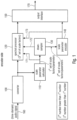
- Fig. 1 illustrates an apparatus for encoding an audio signal 160.
- the audio signal 160 preferably is available in the time-domain, although other representations of the audio signal such as a prediction-domain or any other domain would principally also be useful.
- the apparatus comprises a converter 100, a scale factor calculator 110, a spectral processor 120, a downsampler 130, a scale factor encoder 140 and an output interface 150.
- the converter 100 is configured for converting the audio signal 160 into a spectral representation.
- the scale factor calculator 110 is configured for calculating a first set of scale parameters or scale factors from the spectral representation.
- scaling factor or “scale parameter” is used in order to refer to the same parameter or value, i.e., a value or parameter that is, subsequent to some processing, used for weighting some kind of spectral values.
- This weighting when performed in the linear domain is actually a multiplying operation with a scaling factor.
- the weighting operation with a scale factor is done by an actual addition or subtraction operation.
- scaling does not only mean multiplying or dividing but also means, depending on the certain domain, addition or subtraction or, generally means each operation, by which the spectral value, for example, is weighted or modified using the scale factor or scale parameter.
- the downsampler 130 is configured for downsampling the first set of scale parameters to obtain a second set of scale parameters, wherein a second number of the scale parameters in the second set of scale parameters is lower than a first number of scale parameters in the first set of scale parameters. This is also outlined in the box in Fig. 1 stating that the second number is lower than the first number.
- the scale factor encoder is configured for generating an encoded representation of the second set of scale factors, and this encoded representation is forwarded to the output interface 150.
- the bitrate for transmitting or storing the encoded representation of the second set of scale factors is lower compared to a situation, in which the downsampling of the scale factors performed in the downsampler 130 would not have been performed.
- the spectral processor 120 is configured for processing the spectral representation output by the converter 100 in Fig. 1 using a third set of scale parameters, the third set of scale parameters or scale factors having a third number of scale factors being greater than the second number of scale factors, wherein the spectral processor 120 is configured to use, for the purpose of spectral processing the first set of scale factors as already available from block 110 via line 171.
- the spectral processor 120 is configured to use the second set of scale factors as output by the downsampler 130 for the calculation of the third set of scale factors as illustrated by line 172.
- the spectral processor 120 uses the encoded representation output by the scale factor/parameter encoder 140 for the purpose of calculating the third set of scale factors as illustrated by line 173 in Fig. 1 .
- the spectral processor 120 does not use the first set of scale factors, but uses either the second set of scale factors as calculated by the downsampler or even more preferably uses the encoded representation or, generally, the quantized second set of scale factors and, then, performs an interpolation operation to interpolate the quantized second set of spectral parameters to obtain the third set of scale parameters that has a higher number of scale parameters due to the interpolation operation.
- the encoded representation of the second set of scale factors that is output by block 140 either comprises a codebook index for a preferably used scale parameter codebook or a set of corresponding codebook indices.
- the encoded representation comprises the quantized scale parameters of quantized scale factors that are obtained, when the codebook index or the set of codebook indices or, generally, the encoded representation is input into a decoder-side vector decoder or any other decoder.
- the spectral processor 120 uses the same set of scale factors that is also available at the decoder-side, i.e., uses the quantized second set of scale parameters together with an interpolation operation to finally obtain the third set of scale factors.
- the third number of scale factors in the third set of scale factors is equal to the first number of scale factors.
- a smaller number of scale factors is also useful.
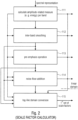
- the scale factor calculator 110 is configured to perform several operations illustrated in Fig. 2 . These operations refer to a calculation 111 of an amplitude-related measure per band.
- a preferred amplitude-related measure per band is the energy per band, but other amplitude-related measures can be used as well, for example, the summation of the magnitudes of the amplitudes per band or the summation of squared amplitudes which corresponds to the energy.
- other powers such as a power of 3 that would reflect the loudness of the signal could also be used and, even powers different from integer numbers such as powers of 1.5 or 2.5 can be used as well in order to calculate amplitude-related measures per band. Even powers less than 1.0 can be used as long as it is made sure that values processed by such powers are positive- valued.
- a further operation performed by the scale factor calculator can be an inter-band smoothing 112.
- This inter-band smoothing is preferably used to smooth out the possible instabilities that can appear in the vector of amplitude-related measures as obtained by step 111. If one would not perform this smoothing, these instabilities would be amplified when converted to a log-domain later as illustrated at 115, especially in spectral values where the energy is close to 0. However, in other embodiments, inter-band smoothing is not performed.
- a further preferred operation performed by the scale factor calculator 110 is the pre-emphasis operation 113.
- This pre-emphasis operation has a similar purpose as a pre-emphasis operation used in an LPC-based perceptual filter of the MDCT-based TCX processing as discussed before with respect to the prior art. This procedure increases the amplitude of the shaped spectrum in the low-frequencies that results in a reduced quantization noise in the low-frequencies.
- the pre-emphasis operation - as the other specific operations - does not necessarily have to be performed.
- a further optional processing operation is the noise-floor addition processing 114.
- This procedure improves the quality of signals containing very high spectral dynamics such as, for example, Glockenspiel, by limiting the amplitude amplification of the shaped spectrum in the valleys, which has the indirect effect of reducing the quantization noise in the peaks, at the cost of an increase of quantization noise in the valleys, where the quantization noise is anyway not perceptible due to masking properties of the human ear such as the absolute listening threshold, the pre-masking, the post-masking or the general masking threshold indicating that, typically, a quite low volume tone relatively close in frequency to a high volume tone is not perceptible at all, i.e., is fully masked or is only roughly perceived by the human hearing mechanism, so that this spectral contribution can be quantized quite coarsely.
- the noise-floor addition operation 114 does not necessarily have to be performed.
- block 115 indicates a log-like domain conversion.
- a transformation of an output of one of blocks 111, 112, 113, 114 in Fig. 2 is performed in a log-like domain.
- a log-like domain is a domain, in which values close to 0 are expanded and high values are compressed.
- the log domain is a domain with basis of 2, but other log domains can be used as well.
- a log domain with the basis of 2 is better for an implementation on a fixed-point signal processor.
- the output of the scale factor calculator 110 is a first set of scale factors.
- each of the blocks 112 to 115 can be bridged, i.e., the output of block 111, for example, could already be the first set of scale factors. However, all the processing operations and, particularly, the log-like domain conversion are preferred. Thus, one could even implement the scale factor calculator by only performing steps 111 and 115 without the procedures in steps 112 to 114, for example.
- the scale factor calculator is configured for performing one or two or more of the procedures illustrated in Fig. 2 as indicated by the input/output lines connecting several blocks.
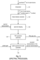
- Fig. 3 illustrates a preferred implementation of the downsampler 130 of Fig. 1 .
- a low-pass filtering or, generally, a filtering with a certain window w(k) is performed in step 131, and, then, a downsampling/decimation operation of the result of the filtering is performed. Due to the fact that low-pass filtering 131 and in preferred embodiments the downsampling/decimation operation 132 are both arithmetic operations, the filtering 131 and the downsampling 132 can be performed within a single operation as will be outlined later on.
- the downsampling/decimation operation is performed in such a way that an overlap among the individual groups of scale parameters of the first set of scale parameters is performed.
- an overlap of one scale factor in the filtering operation between two decimated calculated parameters is performed.
- step 131 performs a low-pass filter on the vector of scale parameters before decimation.
- This low-pass filter has a similar effect as the spreading function used in psychoacoustic models. It reduces the quantization noise at the peaks, at the cost of an increase of quantization noise around the peaks where it is anyway perceptually masked at least to a higher degree with respect to quantization noise at the peaks.
- the downsampler additionally performs a mean value removal 133 and an additional scaling step 134.
- the low-pass filtering operation 131, the mean value removal step 133 and the scaling step 134 are only optional steps.
- the downsampler illustrated in Fig. 3 or illustrated in Fig. 1 can be implemented to only perform step 132 or to perform two steps illustrated in Fig. 3 such as step 132 and one of the steps 131, 133 and 134.
- the downsampler can perform all four steps or only three steps out of the four steps illustrated in Fig. 3 as long as the downsampling/decimation operation 132 is performed.
- Fig. 4 illustrates a preferred implementation of the scale factor encoder 140.
- the scale factor encoder 140 receives the preferably log-like domain second set of scale factors and performs a vector quantization as illustrated in block 141 to finally output one or more indices per frame. These one or more indices per frame can be forwarded to the output interface and written into the bitstream, i.e., introduced into the output encoded audio signal 170 by means of any available output interface procedures.
- the vector quantizer 141 additionally outputs the quantized log-like domain second set of scale factors.
- this data can be directly output by block 141 as indicated by arrow 144.
- a decoder codebook 142 is also available separately in the encoder. This decoder codebook receives the one or more indices per frame and derives, from these one or more indices per frame the quantized preferably log-like domain second set of scale factors as indicated by line 145.
- the decoder codebook 142 will be integrated within the vector quantizer 141.
- the vector quantizer 141 is a multi-stage or split-level or a combined multi-stage/split-level vector quantizer as is, for example, used in any of the indicated prior art procedures.
- the second set of scale factors are the same quantized second set of scale factors that are also available on the decoder-side, i.e., in the decoder that only receives the encoded audio signal that has the one or more indices per frame as output by block 141 via line 146.
- Fig. 5 illustrates a preferred implementation of the spectral processor.
- the spectral processor 120 included within the encoder of Fig. 1 comprises an interpolator 121 that receives the quantized second set of scale parameters and that outputs the third set of scale parameters where the third number is greater than the second number and preferably equal to the first number.
- the spectral processor comprises a linear domain converter 120. Then, a spectral shaping is performed in block 123 using the linear scale parameters on the one hand and the spectral representation on the other hand that is obtained by the converter 100.
- a subsequent temporal noise shaping operation i.e., a prediction over frequency is performed in order to obtain spectral residual values at the output of block 124, while the TNS side information is forwarded to the output interface as indicated by arrow 129.
- the spectral processor 125 has a scalar quantizer/encoder that is configured for receiving a single global gain for the whole spectral representation, i.e., for a whole frame.
- the global gain is derived depending on certain bitrate considerations.
- the global gain is set so that the encoded representation of the spectral representation generated by block 125 fulfils certain requirements such as a bitrate requirement, a quality requirement or both.
- the global gain can be iteratively calculated or can be calculated in a feed forward measure as the case may be.
- the global gain is used together with a quantizer and a high global gain typically results in a coarser quantization where a low global gain results in a finer quantization.
- a high global gain results in a higher quantization step size while a low global gain results in a smaller quantization step size when a fixed quantizer is obtained.
- other quantizers can be used as well together with the global gain functionality such as a quantizer that has some kind of compression functionality for high values, i.e., some kind of non-linear compression functionality so that, for example, the higher values are more compressed than lower values.
- the above dependency between the global gain and the quantization coarseness is valid, when the global gain is multiplied to the values before the quantization in the linear domain corresponding to an addition in the log domain. If, however, the global gain is applied by a division in the linear domain, or by a subtraction in the log domain, the dependency is the other way round. The same is true, when the "global gain" represents an inverse value.
- the bands are non-uniform and follow the perceptually-relevant bark scale (smaller in low-frequencies, larger in high-frequencies).
- this step is mainly used to smooth the possible instabilities that can appear in the vector E B (b). If not smoothed, these instabilities are amplified when converted to log-domain (see step 5), especially in the valleys where the energy is close to 0.
- the pre-emphasis used in this step has the same purpose as the pre-emphasis used in the LPC-based perceptual filter of prior art 2, it increases the amplitude of the shaped Spectrum in the low-frequencies, resulting in reduced quantization noise in the low-frequencies.
- This step improves quality of signals containing very high spectral dynamics such as e.g. glockenspiel, by limiting the amplitude amplification of the shaped spectrum in the valleys, which has the indirect effect of reducing the quantization noise in the peaks, at the cost of an increase of quantization noise in the valleys where it is anyway not perceptible.
- This step applies a low-pass filter (w(k)) on the vector E L (b) before decimation.
- This low-pass filter has a similar effect as the spreading function used in psychoacoustic models: it reduces the quantization noise at the peaks, at the cost of an increase of quantization noise around the peaks where it is anyway perceptually masked.
- the mean can be removed without any loss of information. Removing the mean also allows more efficient vector quantization.
- the scaling of 0.85 slightly compress the amplitude of the noise shaping curve. It has a similar perceptual effect as the spreading function mentioned in Step 6: reduced quantization noise at the peaks and increased quantization noise in the valleys.
- the scale factors are quantized using vector quantization, producing indices which are then packed into the bitstream and sent to the decoder, and quantized scale factors scfQ(n).
- Interpolation is used to get a smooth noise shaping curve and thus to avoid any big amplitude jumps between adjacent bands.
- Fig. 8 illustrates a preferred implementation of an apparatus for decoding an encoded audio signal 250 comprising information on an encoded spectral representation and information on an encoded representation of a second set of scale parameters.
- the decoder comprises an input interface 200, a spectrum decoder 210, a scale factor/parameter decoder 220, a spectral processor 230 and a converter 240.
- the input interface 200 is configured for receiving the encoded audio signal 250 and for extracting the encoded spectral representation that is forwarded to the spectrum decoder 210 and for extracting the encoded representation of the second set of scale factors that is forwarded to the scale factor decoder 220.
- the spectrum decoder 210 is configured for decoding the encoded spectral representation to obtain a decoded spectral representation that is forwarded to the spectral processor 230.
- the scale factor decoder 220 is configured for decoding the encoded second set of scale parameters to obtain a first set of scale parameters forwarded to the spectral processor 230.
- the first set of scale factors has a number of scale factors or scale parameters that is greater than the number of scale factors or scale parameters in the second set.
- the spectral processor 230 is configured for processing the decoded spectral representation using the first set of scale parameters to obtain a scaled spectral representation.
- the scaled spectral representation is then converted by the converter 240 to finally obtain the decoded audio signal 260.
- the scale factor decoder 220 is configured to operate in substantially the same manner as has been discussed with respect to the spectral processor 120 of Fig. 1 relating to the calculation of the third set of scale factors or scale parameters as discussed in connection with blocks 141 or 142 and, particularly, with respect to blocks 121, 122 of Fig. 5 .
- the scale factor decoder is configured to perform the substantially same procedure for the interpolation and the transformation back into the linear domain as has been discussed before with respect to step 9.
- the scale factor decoder 220 is configured for applying a decoder codebook 221 to the one or more indices per frame representing the encoded scale parameter representation.
- an interpolation is performed in block 222 that is substantially the same interpolation as has been discussed with respect to block 121 in Fig. 5 .
- a linear domain converter 223 is used that is substantially the same linear domain converter 122 as has been discussed with respect to Fig. 5 .
- blocks 221, 222, 223 can operate different from what has been discussed with respect to the corresponding blocks on the encoder-side.
- the spectrum decoder 210 illustrated in Fig. 8 comprises a dequantizer/decoder block that receives, as an input, the encoded spectrum and that outputs a dequantized spectrum that is preferably dequantized using the global gain that is additionally transmitted from the encoder side to the decoder side within the encoded audio signal in an encoded form.
- the dequantizer/decoder 210 can, for example, comprise an arithmetic or Huffman decoder functionality that receives, as an input, some kind of codes and that outputs quantization indices representing spectral values.
- these quantization indices are input into a dequantizer together with the global gain and the output are dequantized spectral values that can then be subjected to a TNS processing such as an inverse prediction over frequency in a TNS decoder processing block 211 that, however, is optional.
- a TNS processing such as an inverse prediction over frequency in a TNS decoder processing block 211 that, however, is optional.
- the TNS decoder processing block additionally receives the TNS side information that has been generated by block 124 of Fig. 5 as indicated by line 129.
- the output of the TNS decoder processing step 211 is input into a spectral shaping block 212, where the first set of scale factors as calculated by the scale factor decoder are applied to the decoded spectral representation that can or cannot be TNS processed as the case may be, and the output is the scaled spectral representation that is then input into the converter 240 of Fig. 8 .
- the vector quantizer indices produced in encoder step 8 are read from the bitstream and used to decode the quantized scale factors scfQ ( n ) .
- the SNS scale factors g SNS ( b ) are applied on the quantized MDCT frequency lines for each band separately in order to generate the decoded spectrum X ⁇ ( k ) as outlined by the following code.
- Fig.6 and Fig. 7 illustrate a general encoder/decoder setup where Fig. 6 represents an implementation without TNS processing, while Fig. 7 illustrates an implementation that comprises TNS processing. Similar functionalities illustrated in Fig. 6 and Fig. 7 correspond to similar functionalities in the other figures when identical reference numerals are indicated. Particularly, as illustrated in Fig. 6 , the input signal 160 is input into a transform stage 110 and, subsequently, the spectral processing 120 is performed. Particularly, the spectral processing is reflected by an SNS encoder indicated by reference numerals 123, 110, 130, 140 indicating that the block SNS encoder implements the functionalities indicated by these reference numerals.
- a quantization encoding operation 125 is performed, and the encoded signal is input into the bitstream as indicated at 180 in Fig. 6 .
- the bitstream 180 then occurs at the decoder-side and subsequent to an inverse quantization and decoding illustrated by reference numeral 210, the SNS decoder operation illustrated by blocks 210, 220, 230 of Fig. 8 are performed so that, in the end, subsequent to an inverse transform 240, the decoded output signal 260 is obtained.
- Fig. 7 illustrates a similar representation as in Fig. 6 , but it is indicated that, preferably, the TNS processing is performed subsequent to SNS processing on the encoder-side and, correspondingly, the TNS processing 211 is performed before the SNS processing 212 with respect to the processing sequence on the decoder-side.
- TNS Temporal Noise Shaping
- SNS Spectral Noise Shaping
- quantization/coding see block diagram below
- TNS Temporal Noise Shaping
- TNS also shapes the quantization noise but does a time-domain shaping (as opposed to the frequency-domain shaping of SNS) as well.
- TNS is useful for signals containing sharp attacks and for speech signals.
- TNS is usually applied (in AAC for example) between the transform and SNS.
- Fig. 10 illustrates a preferred subdivision of the spectral coefficients or spectral lines as obtained by block 100 on the encoder-side into bands. Particularly, it is indicated that lower bands have a smaller number of spectral lines than higher bands.
- Fig. 10 corresponds to the index of bands and illustrates the preferred embodiment of 64 bands and the y-axis corresponds to the index of the spectral lines illustrating 320 spectral coefficients in one frame.
- Fig. 10 illustrates exemplarily the situation of the super wide band (SWB) case where there is a sampling frequency of 32 kHz.
- SWB super wide band
- the situation with respect to the individual bands is so that one frame results in 160 spectral lines and the sampling frequency is 16 kHz so that, for both cases, one frame has a length in time of 10 milliseconds.
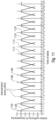
- Fig. 11 illustrates more details on the preferred downsampling performed in the downsampler 130 of Fig. 1 or the corresponding upsampling or interpolation as performed in the scale factor decoder 220 of Fig. 8 or as illustrated in block 222 of Fig. 9 .
- the index for the bands 0 to 63 is given. Particularly, there are 64 bands going from 0 to 63.
- the 16 downsample points corresponding to scfQ(i) are illustrated as vertical lines 1100.
- Fig. 11 illustrates how a certain grouping of scale parameters is performed to finally obtain the downsampled point 1100.
- the first block of four bands consists of (0, 1, 2, 3) and the middle point of this first block is at 1.5 indicated by item 1100 at the index 1.5 along the x-axis.
- the second block of four bands is (4. 5, 6, 7), and the middle point of the second block is 5.5.
- the windows 1110 correspond to the windows w(k) discussed with respect to the step 6 downsampling described before. It can be seen that these windows are centered at the downsampled points and there is the overlap of one block to each side as discussed before.
- the interpolation step 222 of Fig. 9 recovers the 64 bands from the 16 downsampled points. This is seen in Fig. 11 by computing the position of any of the lines 1120 as a function of the two downsampled points indicated at 1100 around a certain line 1120.
- the following example exemplifies that.
- Fig. 12a illustrates a schedule for indicating the framing performed on the encoder-side within converter 100.
- Fig. 12b illustrates a preferred implementation of the converter 100 of Fig. 1 on the encoder-side and Fig. 12c illustrates a preferred implementation of the converter 240 on the decoder-side.
- the converter 100 on the encoder-side is preferably implemented to perform a framing with overlapping frames such as a 50% overlap so that frame 2 overlaps with frame 1 and frame 3 overlaps with frame 2 and frame 4.
- a framing with overlapping frames such as a 50% overlap so that frame 2 overlaps with frame 1 and frame 3 overlaps with frame 2 and frame 4.
- other overlaps or a non-overlapping processing can be performed as well, but it is preferred to perform a 50% overlap together with an MDCT algorithm.
- the converter 100 comprises an analysis window 101 and a subsequently-connected spectral converter 102 for performing an FFT processing, an MDCT processing or any other kind of time-to-spectrum conversion processing to obtain a sequence of frames corresponding to a sequence of spectral representations as input in Fig. 1 to the blocks subsequent to the converter 100.
- the scaled spectral representation(s) are input into the converter 240 of Fig. 8 .
- the converter comprises a time-converter 241 implementing an inverse FFT operation, an inverse MDCT operation or a corresponding spectrum-to-time conversion operation.
- the output is inserted into a synthesis window 242 and the output of the synthesis window 242 is input into an overlap-add processor 243 to perform an overlap-add operation in order to finally obtain the decoded audio signal.
- the overlap-add processing in block 243 performs a sample-by-sample addition between corresponding samples of the second half of, for example, frame 3 and the first half of frame 4 so that the audio sampling values for the overlap between frame 3 and frame 4 as indicated by item 1200 in Fig. 12a is obtained. Similar overlap-add operations in a sample-by-sample manner are performed to obtain the remaining audio sampling values of the decoded audio output signal.
- An inventively encoded audio signal can be stored on a digital storage medium or a non-transitory storage medium or can be transmitted on a transmission medium such as a wireless transmission medium or a wired transmission medium such as the Internet.
- aspects have been described in the context of an apparatus, it is clear that these aspects also represent a description of the corresponding method, where a block or device corresponds to a method step or a feature of a method step. Analogously, aspects described in the context of a method step also represent a description of a corresponding block or item or feature of a corresponding apparatus.
- embodiments of the invention can be implemented in hardware or in software.
- the implementation can be performed using a digital storage medium, for example a floppy disk, a DVD, a CD, a ROM, a PROM, an EPROM, an EEPROM or a FLASH memory, having electronically readable control signals stored thereon, which cooperate (or are capable of cooperating) with a programmable computer system such that the respective method is performed.
- a digital storage medium for example a floppy disk, a DVD, a CD, a ROM, a PROM, an EPROM, an EEPROM or a FLASH memory, having electronically readable control signals stored thereon, which cooperate (or are capable of cooperating) with a programmable computer system such that the respective method is performed.
- Some embodiments according to the invention comprise a data carrier having electronically readable control signals, which are capable of cooperating with a programmable computer system, such that one of the methods described herein is performed.
- embodiments of the present invention can be implemented as a computer program product with a program code, the program code being operative for performing one of the methods when the computer program product runs on a computer.
- the program code may for example be stored on a machine readable carrier.
- inventions comprise the computer program for performing one of the methods described herein, stored on a machine readable carrier or a non-transitory storage medium.
- an embodiment of the inventive method is, therefore, a computer program having a program code for performing one of the methods described herein, when the computer program runs on a computer.
- a further embodiment of the inventive methods is, therefore, a data carrier (or a digital storage medium, or a computer-readable medium) comprising, recorded thereon, the computer program for performing one of the methods described herein.
- a further embodiment of the inventive method is, therefore, a data stream or a sequence of signals representing the computer program for performing one of the methods described herein.
- the data stream or the sequence of signals may for example be configured to be transferred via a data communication connection, for example via the Internet.
- a further embodiment comprises a processing means, for example a computer, or a programmable logic device, configured to or adapted to perform one of the methods described herein.
- a processing means for example a computer, or a programmable logic device, configured to or adapted to perform one of the methods described herein.
- a further embodiment comprises a computer having installed thereon the computer program for performing one of the methods described herein.
- a programmable logic device for example a field programmable gate array
- a field programmable gate array may cooperate with a microprocessor in order to perform one of the methods described herein.
- the methods are preferably performed by any hardware apparatus.
Landscapes
- Engineering & Computer Science (AREA)
- Physics & Mathematics (AREA)
- Computational Linguistics (AREA)
- Signal Processing (AREA)
- Health & Medical Sciences (AREA)
- Audiology, Speech & Language Pathology (AREA)
- Human Computer Interaction (AREA)
- Acoustics & Sound (AREA)
- Multimedia (AREA)
- Spectroscopy & Molecular Physics (AREA)
- Compression, Expansion, Code Conversion, And Decoders (AREA)
Claims (18)
- Appareil pour coder un signal audio (160), comprenant:un convertisseur (100) destiné à convertir le signal audio (160) en une représentation spectrale;un calculateur de paramètres d'échelle (110) destiné à calculer un premier ensemble de paramètres d'échelle à partir de la représentation spectrale;un échantillonneur vers le bas (130) destiné à échantillonner vers le bas le premier ensemble de paramètres d'échelle pour obtenir un deuxième ensemble de paramètres d'échelle, où un deuxième nombre de paramètres d'échelle dans le deuxième ensemble de paramètres d'échelle est inférieur à un premier nombre de paramètres de paramètres d'échelle dans le premier ensemble de paramètres d'échelle;un codeur de paramètres d'échelle (140) destiné à générer une représentation codée du deuxième ensemble de paramètres d'échelle;un processeur spectral (120) destiné à traiter la représentation spectrale à l'aide d'un troisième ensemble de paramètres d'échelle, le troisième ensemble de paramètres d'échelle présentant un troisième nombre de paramètres d'échelle qui est supérieur au deuxième nombre de paramètres d'échelle, où le processeur spectral (120) est configuré pour utiliser le premier ensemble de paramètres d'échelle ou pour dériver le troisième ensemble de paramètres d'échelle du deuxième ensemble de paramètres d'échelle ou de la représentation codée du deuxième ensemble de paramètres d'échelle à l'aide d'une opération d'interpolation; etune interface de sortie (150) destinée à générer un signal de sortie codé (170) comprenant des informations sur une représentation codée de la représentation spectrale et des informations sur une représentation codée du deuxième ensemble de paramètres d'échelle,dans lequel le calculateur de paramètres d'échelle (110) est configuré pour calculer, pour chaque bande parmi une pluralité de bandes de la représentation spectrale, une mesure relative à l'amplitude dans un domaine linéaire pour obtenir un premier ensemble de mesures dans le domaine linéaire; et pour transformer le premier ensemble de mesures dans le domaine linéaire à un domaine logarithmique pour obtenir un premier ensemble de mesures dans le domaine logarithmique; etdans lequel l'échantillonneur vers le bas (130) est configuré pour échantillonner vers le bas le premier ensemble de paramètres d'échelle dans le domaine logarithmique pour obtenir le deuxième ensemble de paramètres d'échelle dans le domaine logarithmique.
- Appareil selon la revendication 1,
dans lequel le processeur spectral (120) est configuré pour utiliser le premier ensemble de paramètres d'échelle dans le domaine linéaire pour traiter la représentation spectrale ou pour interpoler le deuxième ensemble de paramètres d'échelle dans le domaine logarithmique pour obtenir des paramètres d'échelle dans le domaine logarithmique interpolés et pour transformer les paramètres d'échelle dans le domaine logarithmique au domaine linéaire pour obtenir le troisième ensemble de paramètres d'échelle. - Appareil selon l'une des revendications précédentes,dans lequel le calculateur de paramètres d'échelle (110) est configuré pour calculer le premier ensemble de paramètres d'échelle pour des bandes non uniformes, etdans lequel l'échantillonneur vers le bas (130) est configuré pour échantillonner vers le bas le premier ensemble de paramètres d'échelle pour obtenir un premier paramètre d'échelle du deuxième ensemble en combinant un premier groupe présentant un premier nombre prédéfini de paramètres d'échelle adjacents en fréquence du premier ensemble, et dans lequel l'échantillonneur vers le bas (130) est configuré pour échantillonner vers le bas le premier ensemble de paramètres d'échelle pour obtenir un deuxième paramètre d'échelle du deuxième ensemble en combinant un deuxième groupe présentant un deuxième nombre prédéfini de paramètres d'échelle adjacents en fréquence du premier ensemble, dans lequel le deuxième nombre prédéfini est égal au premier nombre prédéfini, et dans lequel le deuxième groupe présente des membres qui sont différents des membres du premier groupe.
- Appareil selon la revendication 3, dans lequel le premier groupe de paramètres d'échelle adjacents en fréquence du premier ensemble et le deuxième groupe de paramètres d'échelle adjacents en fréquence du premier ensemble présentent au moins un paramètre d'échelle du premier ensemble en commun, de sorte que le premier groupe et le deuxième groupe viennent en chevauchement l'un avec l'autre.
- Appareil selon l'une des revendications précédentes, dans lequel l'échantillonneur vers le bas (130) est configuré pour utiliser une opération de moyenne parmi un groupe de premiers paramètres d'échelle, le groupe présentant deux membres ou plus.
- Appareil selon la revendication 5,
dans lequel l'opération de moyenne est une opération de moyenne pondérée configurée pour pondérer un paramètre d'échelle au milieu du groupe plus fortement qu'un paramètre d'échelle au niveau d'un bord du groupe. - Appareil selon l'une des revendications précédentes,dans lequel l'échantillonneur vers le bas (130) est configuré pour effectuer une suppression de valeur moyenne (133) de sorte que le deuxième ensemble de paramètres d'échelle soit exempt de moyenne, oudans lequel l'échantillonneur vers le bas (130) est configuré pour effectuer une opération de mise à échelle (134) à l'aide d'un paramètre de mise à échelle inférieur à 1,0 et supérieur à 0,0 dans le domaine logarithmique, oudans lequel le codeur de paramètres d'échelle (140) est configuré pour quantifier et coder le deuxième ensemble à l'aide d'un quantificateur de vecteurs (141), dans lequel la représentation codée comprend un ou plusieurs indices (146) pour un ou plusieurs livres de codes de quantificateur de vecteurs, oudans lequel le codeur de paramètres d'échelle (140) est configuré pour fournir un deuxième ensemble de paramètres d'échelle quantifiés associés à la représentation codée (142), et dans lequel le processeur spectral (120) est configuré pour dériver le deuxième ensemble de paramètres d'échelle du deuxième ensemble de paramètres d'échelle quantifiés (145), oudans lequel le processeur spectral (120) est configuré pour déterminer ce troisième ensemble de paramètres d'échelle de sorte que le troisième nombre soit égal au premier nombre, oudans lequel le processeur spectral (120) est configuré pour déterminer un paramètre d'échelle interpolé (121) sur base d'un paramètre d'échelle quantifié et d'une différence entre le paramètre d'échelle quantifié et un paramètre d'échelle quantifié suivant dans une séquence ascendante de paramètres d'échelle quantifiés par rapport à la fréquence.
- Appareil selon la revendication 7,
le processeur spectral (120) est configuré pour déterminer, à partir du paramètre d'échelle quantifié et de la différence, au moins deux paramètres d'échelle interpolés, dans lequel est utilisé, pour chacun des deux paramètres d'échelle interpolés, un facteur de pondération différent. - Appareil selon l'une des revendications précédentes,dans lequel le processeur spectral (120) est configuré pour effectuer l'opération d'interpolation (121) dans le domaine logarithmique, et pour convertir (122) les paramètres d'échelle interpolés au domaine linéaire pour obtenir le troisième ensemble de paramètres d'échelle, oudans lequel le calculateur de paramètres d'échelle (110) est configuré pour calculer une mesure relative à l'amplitude pour chaque bande pour obtenir un ensemble de mesures relatives à l'amplitude (111), et pour lisser (112) les mesures relatives à l'amplitude pour obtenir un ensemble de mesures relatives à l'amplitude lissées comme premier ensemble de paramètres d'échelle, oudans lequel le calculateur de paramètres d'échelle (110) est configuré pour calculer une mesure relative à l'amplitude pour chaque bande pour obtenir un ensemble de mesures relatives à l'amplitude, et pour effectuer (113) une opération de préaccentuation sur l'ensemble de mesures relatives à l'amplitude, dans lequel l'opération de préaccentuation est telle que les amplitudes de basses fréquences sont accentuées par rapport aux amplitudes de hautes fréquences, oudans lequel le calculateur de paramètres d'échelle (110) est configuré pour calculer une mesure relative à l'amplitude pour chaque bande pour obtenir un ensemble de mesures relatives à l'amplitude, et pour effectuer une opération d'addition de plancher de bruit (114), dans lequel un plancher de bruit est calculé à partir d'une mesure relative à l'amplitude dérivée comme valeur moyenne d'au moins deux bandes de fréquences de la représentation spectrale, ou dans lequel le calculateur de paramètres d'échelle (110) est configuré pour effectuer au moins l'une parmi un groupe d'opérations, le groupe d'opérations comprenant le fait de calculer (111) les mesures relatives à l'amplitude pour une pluralité de bandes, d'effectuer (112) une opération de lissage, d'effectuer (113) une opération de préaccentuation, d'effectuer (114) une opération d'addition de plancher de bruit et d'effectuer une opération de conversion de domaine logarithmique (115) pour obtenir le premier ensemble de paramètres d'échelle, oudans lequel le processeur spectral (120) est configuré pour pondérer (123) les valeurs spectrales dans la représentation spectrale à l'aide du troisième ensemble de paramètres d'échelle pour obtenir une représentation spectrale pondérée et pour appliquer une opération de mise en forme de bruit temporel (TNS) (124) à la représentation spectrale pondérée, et dans lequel le processeur spectral (120) est configuré pour quantifier (125) et coder un résultat de l'opération de mise en forme de bruit temporel (124) pour obtenir la représentation codée de la représentation spectrale, oudans lequel le convertisseur (100) comprend un diviseur en fenêtres d'analyse (101) destiné à générer une séquence de blocs d'échantillons audio divisés en fenêtres, et un convertisseur de spectre temporel (102) destiné à convertir les blocs d'échantillons audio divisés en fenêtres en une séquence de représentations spectrales, une représentation spectrale étant une trame spectrale, oudans lequel le convertisseur (100) est configuré pour appliquer une opération de MDCT (transformée cosinusoïdale discrète modifiée) pour obtenir un spectre de MDCT à partir d'un bloc d'échantillons dans le domaine temporel, oudans lequel le calculateur de paramètres d'échelle (110) est configuré pour calculer, pour chaque bande, une énergie de la bande, le calcul comprenant le fait d'élever au carré les lignes spectrales, d'additionner les lignes spectrales élevées au carré et de diviser les lignes spectrales élevées au carré par un nombre de lignes dans la bande, oudans lequel le processeur spectral (120) est configuré pour pondérer (123) les valeurs spectrales de la représentation spectrale ou pour pondérer (123) les valeurs spectrales dérivées de la représentation spectrale selon un schéma de bandes, le schéma de bandes étant identique au schéma de bandes utilisé lors du calcul du premier ensemble de paramètres d'échelle par le calculateur de paramètres d'échelle (110), oudans lequel un nombre de bandes est 64, le premier nombre est 64, le deuxième nombre est 16 et le troisième nombre est 64, oudans lequel le processeur spectral (120) est configuré pour calculer un gain global pour toutes les bandes et pour quantifier (125) les valeurs spectrales suite à une mise à échelle (123) impliquant le troisième nombre de paramètres d'échelle à l'aide d'un quantificateur scalaire, dans lequel le processeur spectral (120) est configuré pour commander une grandeur de pas du quantificateur scalaire (125) en fonction du gain global.
- Procédé de codage d'un signal audio (160), comprenant le fait de:convertir (100) le signal audio (160) en une représentation spectrale;calculer (110) un premier ensemble de paramètres d'échelle à partir de la représentation spectrale;échantillonner vers le bas (130) le premier ensemble de paramètres d'échelle pour obtenir un deuxième ensemble de paramètres d'échelle, où un deuxième nombre de paramètres d'échelle dans le deuxième ensemble de paramètres d'échelle est inférieur à un premier nombre de paramètres d'échelle dans le premier ensemble d'échelles paramètres;générer (140) une représentation codée du deuxième ensemble de paramètres d'échelle;traiter (120) la représentation spectrale à l'aide d'un troisième ensemble de paramètres d'échelle, le troisième ensemble de paramètres d'échelle présentant un troisième nombre de paramètres d'échelle qui est supérieur au deuxième nombre de paramètres d'échelle, où le traitement (120) utilise le premier ensemble de paramètres d'échelle ou dérive le troisième ensemble de paramètres d'échelle du deuxième ensemble de paramètres d'échelle ou de la représentation codée du deuxième ensemble de paramètres d'échelle à l'aide d'une opération d'interpolation; etgénérer (150) un signal de sortie codé (170) comprenant des informations sur une représentation codée de la représentation spectrale et des informations sur une représentation codée du deuxième ensemble de paramètres d'échelle,dans lequel le calcul (110) d'un premier ensemble de paramètres d'échelle comprend le fait de calculer, pour chaque bande parmi une pluralité de bandes de la représentation spectrale, une mesure relative à l'amplitude dans un domaine linéaire pour obtenir un premier ensemble de mesures dans le domaine linéaire; et de transformer le premier ensemble de mesures dans le domaine linéaire à un domaine logarithmique pour obtenir le premier ensemble de mesures dans le domaine logarithmique; etdans lequel le -l'échantillonnage vers le bas (130) comprend le fait d'échantillonner vers le bas le premier ensemble de paramètres d'échelle dans le domaine logarithmique pour obtenir le deuxième ensemble de paramètres de calculateur d'échelle dans le domaine logarithmique.
- Appareil pour décoder un signal audio codé (250) comprenant des informations sur une représentation spectrale codée et des informations sur une représentation codée d'un deuxième ensemble de paramètres d'échelle, comprenant:une interface d'entrée (200) destinée à recevoir le signal audio codé (250) et à extraire la représentation spectrale codée et la représentation codée du deuxième ensemble de paramètres d'échelle;un décodeur de spectre (210) destiné à décoder la représentation spectrale codée pour obtenir une représentation spectrale décodée;un décodeur de paramètres d'échelle (220) destiné à décoder le deuxième ensemble codé de paramètres d'échelle pour obtenir un premier ensemble de paramètres d'échelle, où un nombre de paramètres d'échelle du deuxième ensemble est inférieur à un nombre de paramètres d'échelle du premier ensemble;un processeur spectral (230) destiné à traiter la représentation spectrale décodée à l'aide du premier ensemble de paramètres d'échelle pour obtenir une représentation spectrale mise à échelle; etun convertisseur (240) destiné à convertir la représentation spectrale mise à échelle pour obtenir un signal audio décodé (260),dans lequel le décodeur de paramètres d'échelle (220) est configuré pour interpoler (222) le deuxième ensemble de paramètres d'échelle dans le domaine logarithmique pour obtenir des paramètres d'échelle dans le domaine logarithmique interpolés.
- Appareil selon la revendication 11,dans lequel le décodeur de paramètres d'échelle (220) est configuré pour décoder la représentation spectrale codée à l'aide d'un déquantificateur de vecteurs (210) fournissant, pour un ou plusieurs indices de quantification, le deuxième ensemble de paramètres d'échelle décodés, et dans lequel le décodeur de paramètres d'échelle (220) est configuré pour interpoler (222) le deuxième ensemble de paramètres d'échelle décodés pour obtenir le premier ensemble de paramètres d'échelle, oudans lequel le décodeur de paramètres d'échelle (220) est configuré pour déterminer un paramètre d'échelle interpolé sur base d'un paramètre d'échelle quantifié et d'une différence entre le paramètre d'échelle quantifié et un paramètre d'échelle quantifié suivant dans une séquence ascendante de paramètres d'échelle quantifiés par rapport à la fréquence.
- Appareil selon la revendication 12,
dans lequel le décodeur de paramètres d'échelle (220) est configuré pour déterminer, à partir du paramètre d'échelle quantifié et de la différence, au moins deux paramètres d'échelle interpolés, où est utilisé, pour la génération de chacun des deux paramètres d'échelle interpolés, un facteur de pondération différent. - Appareil selon la revendication 13,dans lequel le décodeur de paramètres d'échelle (220) est configuré pour utiliser les facteurs de pondération, dans lequel les facteurs de pondération augmentent au fur et à mesure qu'augmentent les fréquences associées aux paramètres d'échelle interpolés, oudans lequel le décodeur de paramètres d'échelle (220) est configuré pour effectuer une opération d'interpolation (222) dans le domaine logarithmique, et pour convertir (223) les paramètres d'échelle interpolés au domaine linéaire pour obtenir le premier ensemble de paramètres d'échelle, dans lequel le domaine logarithmique est un domaine logarithmique avec une base de 10 ou avec une base de 2, oudans lequel le processeur spectral (230) est configuré pour appliquer (211) une opération de décodeur de mise en forme de bruit temporel (TNS) à la représentation spectrale décodée pour obtenir une représentation spectrale décodée de TNS, et pour pondérer (212) la représentation spectrale décodée de TNS à l'aide du premier ensemble de paramètres d'échelle, oudans lequel le décodeur de paramètres d'échelle (220) est configuré pour interpoler les paramètres d'échelle quantifiés de sorte que les paramètres d'échelle quantifiés interpolés présentent des valeurs qui se situent dans une plage de ± 20 % des valeurs obtenues à l'aide des équations suivantes:


 où scfQ(n) est le paramètre d'échelle quantifié pour un indice n, et où scfQint(k) est le paramètre d'échelle interpolé pour un indice k, oudans lequel le décodeur de paramètres d'échelle (220) est configuré pour effectuer une interpolation (222) pour obtenir les paramètres d'échelle dans, en ce qui concerne la fréquence, le premier ensemble de paramètres d'échelle et pour effectuer une opération d'extrapolation pour obtenir les paramètres d'échelle au niveau des bords, en ce qui concerne la fréquence, du premier ensemble de paramètres d'échelle,
 - Appareil selon la revendication 14,
dans lequel le décodeur de paramètres d'échelle (220) est configuré pour déterminer au moins un premier paramètre d'échelle et un dernier paramètre d'échelle du premier ensemble de paramètres d'échelle en ce qui concerne les bandes de fréquences ascendantes par une opération d'extrapolation. - Appareil selon l'une des revendications 10 à 15,dans lequel le décodeur de paramètres d'échelle (220) est configuré pour effectuer une interpolation (222) et une transformée successive du domaine logarithmique au domaine linéaire, dans lequel le domaine logarithmique est un domaine logarithmique 2 et dans lequel les valeurs du domaine linéaire sont calculées à l'aide d'une élévation à la puissance avec une base de deux, oudans lequel le signal audio codé (250) comprend des informations sur un gain global pour la représentation spectrale codée, dans lequel le décodeur de spectre (210) est configuré pour déquantifier (210) la représentation spectrale codée à l'aide du gain global, et dans lequel le processeur spectral (230) est configuré pour traiter la représentation spectrale déquantifiée ou les valeurs dérivées de la représentation spectrale déquantifiée en pondérant chaque valeur spectrale déquantifiée ou chaque valeur dérivée de la représentation spectrale déquantifiée d'une bande à l'aide du même paramètre d'échelle du premier ensemble de paramètres d'échelle pour la bande, oudans lequel le convertisseur (240) est configuré pour convertir (241) les représentations spectrales mises à échelle successives dans le temps; pour diviser en fenêtres de synthèse (242) les représentations spectrales mises à échelle successives dans le temps converties, et pour additionner à chevauchement (243) les représentations converties divisées en fenêtres pour obtenir un signal audio décodé (260), oudans lequel le convertisseur (240) comprend un convertisseur à transformée cosinusoïdale discrète modifiée (MDCT) inverse, oudans lequel le processeur spectral (230) est configuré pour multiplier les valeurs spectrales par les paramètres d'échelle correspondants du premier ensemble de paramètres d'échelle, oudans lequel un deuxième nombre de paramètres d'échelle dans le deuxième ensemble de paramètres d'échelle est 16 et le premier nombre est 64, oudans lequel chaque paramètre d'échelle du premier ensemble est associé à une bande, dans lequel les bandes correspondant à des fréquences supérieures sont plus larges que les bandes associées à des fréquences inférieures, de sorte qu'un paramètre d'échelle du premier ensemble de paramètres d'échelle associés à une bande de hautes fréquences soit utilisé pour pondérer un nombre supérieur de valeurs spectrales en comparaison avec un paramètre d'échelle associé à une bande de fréquence inférieure, dans lequel le paramètre d'échelle associé à la bande de fréquence inférieure est utilisé pour pondérer un nombre inférieur de valeurs spectrales dans la bande de basses fréquences.
- Procédé de décodage d'un signal audio codé (250) comprenant des informations sur une représentation spectrale codée et des informations sur une représentation codée d'un deuxième ensemble de paramètres d'échelle, comprenant le fait de:recevoir (200) le signal audio codé (250) et extraire la représentation spectrale codée et la représentation codée du deuxième ensemble de paramètres d'échelle;décoder (210) la représentation spectrale codée pour obtenir une représentation spectrale décodée;décoder (220) le deuxième ensemble codé de paramètres d'échelle pour obtenir un premier ensemble de paramètres d'échelle, où un nombre de paramètres d'échelle du deuxième ensemble est inférieur à un nombre de paramètres d'échelle du premier ensemble;traiter (230) la représentation spectrale décodée à l'aide du premier ensemble de paramètres d'échelle pour obtenir une représentation spectrale mise à échelle; etconvertir (240) la représentation spectrale mise à échelle pour obtenir un signal audio décodé (260),dans lequel le décodage (220) du deuxième ensemble codé de paramètres d'échelle comprend le fait d'interpoler (222) le deuxième ensemble de paramètres d'échelle dans un domaine logarithmique pour obtenir des paramètres d'échelle dans le domaine logarithmique interpolés.
- Programme d'ordinateur pour réaliser, lorsqu'il est exécuté sur un ordinateur ou d'un processeur, le procédé selon la revendication 10 ou le procédé selon la revendication 17.
Priority Applications (1)
| Application Number | Priority Date | Filing Date | Title |
|---|---|---|---|
| EP24166212.1A EP4375995B1 (fr) | 2017-11-10 | 2018-11-05 | Appareil et procédé de codage et de décodage d'un signal audio à l'aide d'un sous-échantillonnage ou d'une interpolation de paramètres d'échelle |
Applications Claiming Priority (2)
| Application Number | Priority Date | Filing Date | Title |
|---|---|---|---|
| PCT/EP2017/078921 WO2019091573A1 (fr) | 2017-11-10 | 2017-11-10 | Appareil et procédé de codage et de décodage d'un signal audio utilisant un sous-échantillonnage ou une interpolation de paramètres d'échelle |
| PCT/EP2018/080137 WO2019091904A1 (fr) | 2017-11-10 | 2018-11-05 | Appareil et procédé de codage et de décodage d'un signal audio utilisant un sous-échantillonnage ou une interpolation de paramètres d'échelle |
Related Child Applications (1)
| Application Number | Title | Priority Date | Filing Date |
|---|---|---|---|
| EP24166212.1A Division EP4375995B1 (fr) | 2017-11-10 | 2018-11-05 | Appareil et procédé de codage et de décodage d'un signal audio à l'aide d'un sous-échantillonnage ou d'une interpolation de paramètres d'échelle |
Publications (3)
| Publication Number | Publication Date |
|---|---|
| EP3707709A1 EP3707709A1 (fr) | 2020-09-16 |
| EP3707709C0 EP3707709C0 (fr) | 2024-04-24 |
| EP3707709B1 true EP3707709B1 (fr) | 2024-04-24 |
Family
ID=60388039
Family Applications (2)
| Application Number | Title | Priority Date | Filing Date |
|---|---|---|---|
| EP18793692.7A Active EP3707709B1 (fr) | 2017-11-10 | 2018-11-05 | Dispositif et procédé pour coder et decoder un signal audio par sous-échantillonnage ou interpolation des faits d'échelle |
| EP24166212.1A Active EP4375995B1 (fr) | 2017-11-10 | 2018-11-05 | Appareil et procédé de codage et de décodage d'un signal audio à l'aide d'un sous-échantillonnage ou d'une interpolation de paramètres d'échelle |
Family Applications After (1)
| Application Number | Title | Priority Date | Filing Date |
|---|---|---|---|
| EP24166212.1A Active EP4375995B1 (fr) | 2017-11-10 | 2018-11-05 | Appareil et procédé de codage et de décodage d'un signal audio à l'aide d'un sous-échantillonnage ou d'une interpolation de paramètres d'échelle |
Country Status (17)
| Country | Link |
|---|---|
| US (1) | US11043226B2 (fr) |
| EP (2) | EP3707709B1 (fr) |
| JP (1) | JP7073491B2 (fr) |
| KR (1) | KR102423959B1 (fr) |
| CN (1) | CN111357050B (fr) |
| AR (2) | AR113483A1 (fr) |
| AU (1) | AU2018363652B2 (fr) |
| CA (2) | CA3081634C (fr) |
| ES (2) | ES3036070T3 (fr) |
| MX (1) | MX2020004790A (fr) |
| MY (1) | MY207090A (fr) |
| PL (2) | PL4375995T3 (fr) |
| RU (1) | RU2762301C2 (fr) |
| SG (1) | SG11202004170QA (fr) |
| TW (1) | TWI713927B (fr) |
| WO (2) | WO2019091573A1 (fr) |
| ZA (1) | ZA202002077B (fr) |
Families Citing this family (8)
| Publication number | Priority date | Publication date | Assignee | Title |
|---|---|---|---|---|
| CN111402905B (zh) * | 2018-12-28 | 2023-05-26 | 南京中感微电子有限公司 | 音频数据恢复方法、装置及蓝牙设备 |
| US11527252B2 (en) | 2019-08-30 | 2022-12-13 | Fraunhofer-Gesellschaft zur Förderung der angewandten Forschung e.V. | MDCT M/S stereo |
| US12406037B2 (en) * | 2019-12-18 | 2025-09-02 | Booz Allen Hamilton Inc. | System and method for digital steganography purification |
| WO2022008454A1 (fr) * | 2020-07-07 | 2022-01-13 | Fraunhofer-Gesellschaft zur Förderung der angewandten Forschung e.V. | Quantificateur audio et déquantificateur audio et procédés associés |
| CN115050378B (zh) * | 2022-05-19 | 2024-06-07 | 腾讯科技(深圳)有限公司 | 音频编解码方法及相关产品 |
| WO2024175187A1 (fr) | 2023-02-21 | 2024-08-29 | Fraunhofer-Gesellschaft zur Förderung der angewandten Forschung e.V. | Codeur servant à coder un signal audio multicanal |
| TWI864704B (zh) * | 2023-04-26 | 2024-12-01 | 弗勞恩霍夫爾協會 | 用於音訊編碼器中之尺度參數之諧度相依傾斜控制之設備及方法 |
| AU2023445414A1 (en) | 2023-04-26 | 2025-10-23 | Fraunhofer-Gesellschaft zur Förderung der angewandten Forschung e.V. | Apparatus and method for harmonicity-dependent tilt control of scale parameters in an audio encoder |
Family Cites Families (116)
| Publication number | Priority date | Publication date | Assignee | Title |
|---|---|---|---|---|
| DE3639753A1 (de) * | 1986-11-21 | 1988-06-01 | Inst Rundfunktechnik Gmbh | Verfahren zum uebertragen digitalisierter tonsignale |
| CA2002015C (fr) * | 1988-12-30 | 1994-12-27 | Joseph Lindley Ii Hall | Codage perceptif des signaux audio |
| US5012517A (en) * | 1989-04-18 | 1991-04-30 | Pacific Communication Science, Inc. | Adaptive transform coder having long term predictor |
| US5233660A (en) | 1991-09-10 | 1993-08-03 | At&T Bell Laboratories | Method and apparatus for low-delay celp speech coding and decoding |
| US5581653A (en) * | 1993-08-31 | 1996-12-03 | Dolby Laboratories Licensing Corporation | Low bit-rate high-resolution spectral envelope coding for audio encoder and decoder |
| JP3402748B2 (ja) | 1994-05-23 | 2003-05-06 | 三洋電機株式会社 | 音声信号のピッチ周期抽出装置 |
| EP0732687B2 (fr) | 1995-03-13 | 2005-10-12 | Matsushita Electric Industrial Co., Ltd. | Dispositif d'extension de la largeur de bande d'un signal de parole |
| US5781888A (en) | 1996-01-16 | 1998-07-14 | Lucent Technologies Inc. | Perceptual noise shaping in the time domain via LPC prediction in the frequency domain |
| WO1997027578A1 (fr) | 1996-01-26 | 1997-07-31 | Motorola Inc. | Analyseur de la parole dans le domaine temporel a tres faible debit binaire pour des messages vocaux |
| US5812971A (en) | 1996-03-22 | 1998-09-22 | Lucent Technologies Inc. | Enhanced joint stereo coding method using temporal envelope shaping |
| KR100261253B1 (ko) | 1997-04-02 | 2000-07-01 | 윤종용 | 비트율 조절이 가능한 오디오 부호화/복호화 방법및 장치 |
| GB2326572A (en) | 1997-06-19 | 1998-12-23 | Softsound Limited | Low bit rate audio coder and decoder |
| AU9404098A (en) * | 1997-09-23 | 1999-04-12 | Voxware, Inc. | Scalable and embedded codec for speech and audio signals |
| US6507814B1 (en) | 1998-08-24 | 2003-01-14 | Conexant Systems, Inc. | Pitch determination using speech classification and prior pitch estimation |
| US7272556B1 (en) * | 1998-09-23 | 2007-09-18 | Lucent Technologies Inc. | Scalable and embedded codec for speech and audio signals |
| SE9903553D0 (sv) * | 1999-01-27 | 1999-10-01 | Lars Liljeryd | Enhancing percepptual performance of SBR and related coding methods by adaptive noise addition (ANA) and noise substitution limiting (NSL) |
| US6735561B1 (en) | 2000-03-29 | 2004-05-11 | At&T Corp. | Effective deployment of temporal noise shaping (TNS) filters |
| US7099830B1 (en) | 2000-03-29 | 2006-08-29 | At&T Corp. | Effective deployment of temporal noise shaping (TNS) filters |
| US7395209B1 (en) | 2000-05-12 | 2008-07-01 | Cirrus Logic, Inc. | Fixed point audio decoding system and method |
| US7353168B2 (en) | 2001-10-03 | 2008-04-01 | Broadcom Corporation | Method and apparatus to eliminate discontinuities in adaptively filtered signals |
| US20030187663A1 (en) | 2002-03-28 | 2003-10-02 | Truman Michael Mead | Broadband frequency translation for high frequency regeneration |
| US7447631B2 (en) | 2002-06-17 | 2008-11-04 | Dolby Laboratories Licensing Corporation | Audio coding system using spectral hole filling |
| US7502743B2 (en) * | 2002-09-04 | 2009-03-10 | Microsoft Corporation | Multi-channel audio encoding and decoding with multi-channel transform selection |
| US7433824B2 (en) | 2002-09-04 | 2008-10-07 | Microsoft Corporation | Entropy coding by adapting coding between level and run-length/level modes |
| CN1748247B (zh) | 2003-02-11 | 2011-06-15 | 皇家飞利浦电子股份有限公司 | 音频编码 |
| KR20030031936A (ko) | 2003-02-13 | 2003-04-23 | 배명진 | 피치변경법을 이용한 단일 음성 다중 목소리 합성기 |
| US7983909B2 (en) | 2003-09-15 | 2011-07-19 | Intel Corporation | Method and apparatus for encoding audio data |
| US7009533B1 (en) * | 2004-02-13 | 2006-03-07 | Samplify Systems Llc | Adaptive compression and decompression of bandlimited signals |
| ATE390683T1 (de) * | 2004-03-01 | 2008-04-15 | Dolby Lab Licensing Corp | Mehrkanalige audiocodierung |
| DE102004009949B4 (de) | 2004-03-01 | 2006-03-09 | Fraunhofer-Gesellschaft zur Förderung der angewandten Forschung e.V. | Vorrichtung und Verfahren zum Ermitteln eines Schätzwertes |
| DE102004009954B4 (de) | 2004-03-01 | 2005-12-15 | Fraunhofer-Gesellschaft zur Förderung der angewandten Forschung e.V. | Vorrichtung und Verfahren zum Verarbeiten eines Multikanalsignals |
| US8260611B2 (en) | 2005-04-01 | 2012-09-04 | Qualcomm Incorporated | Systems, methods, and apparatus for highband excitation generation |
| US7546240B2 (en) | 2005-07-15 | 2009-06-09 | Microsoft Corporation | Coding with improved time resolution for selected segments via adaptive block transformation of a group of samples from a subband decomposition |
| US7539612B2 (en) * | 2005-07-15 | 2009-05-26 | Microsoft Corporation | Coding and decoding scale factor information |
| KR100888474B1 (ko) | 2005-11-21 | 2009-03-12 | 삼성전자주식회사 | 멀티채널 오디오 신호의 부호화/복호화 장치 및 방법 |
| US7805297B2 (en) | 2005-11-23 | 2010-09-28 | Broadcom Corporation | Classification-based frame loss concealment for audio signals |
| US8255207B2 (en) | 2005-12-28 | 2012-08-28 | Voiceage Corporation | Method and device for efficient frame erasure concealment in speech codecs |
| CN101395661B (zh) | 2006-03-07 | 2013-02-06 | 艾利森电话股份有限公司 | 音频编码和解码的方法和设备 |
| US8150065B2 (en) | 2006-05-25 | 2012-04-03 | Audience, Inc. | System and method for processing an audio signal |
| JP2009539132A (ja) | 2006-05-30 | 2009-11-12 | コーニンクレッカ フィリップス エレクトロニクス エヌ ヴィ | オーディオ信号の線形予測符号化 |
| US8015000B2 (en) | 2006-08-03 | 2011-09-06 | Broadcom Corporation | Classification-based frame loss concealment for audio signals |
| DE102006049154B4 (de) | 2006-10-18 | 2009-07-09 | Fraunhofer-Gesellschaft zur Förderung der angewandten Forschung e.V. | Kodierung eines Informationssignals |
| JPWO2008072701A1 (ja) | 2006-12-13 | 2010-04-02 | パナソニック株式会社 | ポストフィルタおよびフィルタリング方法 |
| EP2015293A1 (fr) | 2007-06-14 | 2009-01-14 | Deutsche Thomson OHG | Procédé et appareil pour coder et décoder un signal audio par résolution temporelle à commutation adaptative dans le domaine spectral |
| US20110022924A1 (en) | 2007-06-14 | 2011-01-27 | Vladimir Malenovsky | Device and Method for Frame Erasure Concealment in a PCM Codec Interoperable with the ITU-T Recommendation G. 711 |
| WO2009027606A1 (fr) | 2007-08-24 | 2009-03-05 | France Telecom | Codage/decodage par plans de symboles, avec calcul dynamique de tables de probabilites |
| EP2186087B1 (fr) * | 2007-08-27 | 2011-11-30 | Telefonaktiebolaget L M Ericsson (PUBL) | Codage de transformation amélioré de signaux vocaux et audio |
| JP5485909B2 (ja) * | 2007-12-31 | 2014-05-07 | エルジー エレクトロニクス インコーポレイティド | オーディオ信号処理方法及び装置 |
| ATE518224T1 (de) * | 2008-01-04 | 2011-08-15 | Dolby Int Ab | Audiokodierer und -dekodierer |
| RU2475868C2 (ru) | 2008-06-13 | 2013-02-20 | Нокиа Корпорейшн | Способ и устройство для маскирования ошибок кодированных аудиоданных |
| EP2144230A1 (fr) | 2008-07-11 | 2010-01-13 | Fraunhofer-Gesellschaft zur Förderung der angewandten Forschung e.V. | Schéma de codage/décodage audio à taux bas de bits disposant des commutateurs en cascade |
| EP2311034B1 (fr) | 2008-07-11 | 2015-11-04 | Fraunhofer-Gesellschaft zur Förderung der angewandten Forschung e.V. | Encodeur et décodeur audio pour encoder des trames de signaux audio échantillonnés |
| PL2346029T3 (pl) | 2008-07-11 | 2013-11-29 | Fraunhofer Ges Forschung | Koder sygnału audio, sposób kodowania sygnału audio i odpowiadający mu program komputerowy |
| EP2144231A1 (fr) | 2008-07-11 | 2010-01-13 | Fraunhofer-Gesellschaft zur Förderung der angewandten Forschung e.V. | Schéma de codage/décodage audio à taux bas de bits avec du prétraitement commun |
| US8577673B2 (en) | 2008-09-15 | 2013-11-05 | Huawei Technologies Co., Ltd. | CELP post-processing for music signals |
| KR20130069833A (ko) | 2008-10-08 | 2013-06-26 | 프라운호퍼 게젤샤프트 쭈르 푀르데룽 데어 안겐반텐 포르슝 에. 베. | 다중 분해능 스위치드 오디오 부호화/복호화 방법 |
| MX2011007925A (es) | 2009-01-28 | 2011-08-17 | Dten Forschung E V Fraunhofer Ges Zur Foeerderung Der Angewan | Codificador de audio, decodificador de audio, información de audio codificada, métodos para la codificación y decodificación de una señal de audio y programa de computadora. |
| JP4932917B2 (ja) | 2009-04-03 | 2012-05-16 | 株式会社エヌ・ティ・ティ・ドコモ | 音声復号装置、音声復号方法、及び音声復号プログラム |
| FR2944664A1 (fr) | 2009-04-21 | 2010-10-22 | Thomson Licensing | Dispositif et procede de traitement d'images |
| US8428938B2 (en) | 2009-06-04 | 2013-04-23 | Qualcomm Incorporated | Systems and methods for reconstructing an erased speech frame |
| US8352252B2 (en) | 2009-06-04 | 2013-01-08 | Qualcomm Incorporated | Systems and methods for preventing the loss of information within a speech frame |
| KR20100136890A (ko) | 2009-06-19 | 2010-12-29 | 삼성전자주식회사 | 컨텍스트 기반의 산술 부호화 장치 및 방법과 산술 복호화 장치 및 방법 |
| ES2531013T3 (es) | 2009-10-20 | 2015-03-10 | Fraunhofer Ges Forschung | Codificador de audio, decodificador de audio, método para codificar información de audio, método para decodificar información de audio y programa de computación que usa la detección de un grupo de valores espectrales previamente decodificados |
| EP2473995B9 (fr) | 2009-10-20 | 2016-12-21 | Fraunhofer-Gesellschaft zur Förderung der angewandten Forschung e.V. | Codeur de signal audio, décodeur de signal audio, procédé de mise à disposition d'une représentation codée d'un contenu audio, procédé de mise à disposition d'une représentation décodée d'un contenu audio et programme informatique destiné à être utilisé dans les applications à faible retard |
| US8207875B2 (en) | 2009-10-28 | 2012-06-26 | Motorola Mobility, Inc. | Encoder that optimizes bit allocation for information sub-parts |
| US7978101B2 (en) | 2009-10-28 | 2011-07-12 | Motorola Mobility, Inc. | Encoder and decoder using arithmetic stage to compress code space that is not fully utilized |
| US9020812B2 (en) | 2009-11-24 | 2015-04-28 | Lg Electronics Inc. | Audio signal processing method and device |
| BR122021008581B1 (pt) | 2010-01-12 | 2022-08-16 | Fraunhofer-Gesellschaft zur Förderung der angewandten Forschung e.V. | Codificador de áudio, decodificador de áudio, método de codificação e informação de áudio, e método de decodificação de uma informação de áudio que utiliza uma tabela hash que descreve tanto valores de estado significativos como limites de intervalo |
| US20110196673A1 (en) | 2010-02-11 | 2011-08-11 | Qualcomm Incorporated | Concealing lost packets in a sub-band coding decoder |
| EP2375409A1 (fr) | 2010-04-09 | 2011-10-12 | Fraunhofer-Gesellschaft zur Förderung der angewandten Forschung e.V. | Codeur audio, décodeur audio et procédés connexes pour le traitement de signaux audio multicanaux au moyen d'une prédiction complexe |
| FR2961980A1 (fr) | 2010-06-24 | 2011-12-30 | France Telecom | Controle d'une boucle de retroaction de mise en forme de bruit dans un codeur de signal audionumerique |
| KR101696632B1 (ko) | 2010-07-02 | 2017-01-16 | 돌비 인터네셔널 에이비 | 선택적인 베이스 포스트 필터 |
| CN103119646B (zh) | 2010-07-20 | 2016-09-07 | 弗劳恩霍夫应用研究促进协会 | 音频编码器、音频解码器、编码音频信息的方法以及解码音频信息的方法 |
| US8738385B2 (en) | 2010-10-20 | 2014-05-27 | Broadcom Corporation | Pitch-based pre-filtering and post-filtering for compression of audio signals |
| MY165853A (en) | 2011-02-14 | 2018-05-18 | Fraunhofer Ges Forschung | Linear prediction based coding scheme using spectral domain noise shaping |
| US9270807B2 (en) | 2011-02-23 | 2016-02-23 | Digimarc Corporation | Audio localization using audio signal encoding and recognition |
| SG194199A1 (en) | 2011-03-18 | 2013-12-30 | Fraunhofer Ges Forschung | Frame element positioning in frames of a bitstream representing audio content |
| CN103620675B (zh) | 2011-04-21 | 2015-12-23 | 三星电子株式会社 | 对线性预测编码系数进行量化的设备、声音编码设备、对线性预测编码系数进行反量化的设备、声音解码设备及其电子装置 |
| WO2012152764A1 (fr) | 2011-05-09 | 2012-11-15 | Dolby International Ab | Procédé et codeur de traitement de signal audio stéréo numérique |
| FR2977439A1 (fr) | 2011-06-28 | 2013-01-04 | France Telecom | Fenetres de ponderation en codage/decodage par transformee avec recouvrement, optimisees en retard. |
| FR2977969A1 (fr) | 2011-07-12 | 2013-01-18 | France Telecom | Adaptation de fenetres de ponderation d'analyse ou de synthese pour un codage ou decodage par transformee |
| JP5947971B2 (ja) | 2012-04-05 | 2016-07-06 | 華為技術有限公司Huawei Technologies Co.,Ltd. | マルチチャネルオーディオ信号の符号化パラメータを決定する方法及びマルチチャネルオーディオエンコーダ |
| US20130282373A1 (en) | 2012-04-23 | 2013-10-24 | Qualcomm Incorporated | Systems and methods for audio signal processing |
| ES3017132T3 (en) | 2012-06-08 | 2025-05-12 | Samsung Electronics Co Ltd | Method and apparatus for concealing frame error and method and apparatus for audio decoding |
| GB201210373D0 (en) | 2012-06-12 | 2012-07-25 | Meridian Audio Ltd | Doubly compatible lossless audio sandwidth extension |
| FR2992766A1 (fr) | 2012-06-29 | 2014-01-03 | France Telecom | Attenuation efficace de pre-echos dans un signal audionumerique |
| CN102779526B (zh) | 2012-08-07 | 2014-04-16 | 无锡成电科大科技发展有限公司 | 语音信号中基音提取及修正方法 |
| US9406307B2 (en) | 2012-08-19 | 2016-08-02 | The Regents Of The University Of California | Method and apparatus for polyphonic audio signal prediction in coding and networking systems |
| US9293146B2 (en) * | 2012-09-04 | 2016-03-22 | Apple Inc. | Intensity stereo coding in advanced audio coding |
| CN107731237B (zh) | 2012-09-24 | 2021-07-20 | 三星电子株式会社 | 时域帧错误隐藏设备 |
| US9401153B2 (en) | 2012-10-15 | 2016-07-26 | Digimarc Corporation | Multi-mode audio recognition and auxiliary data encoding and decoding |
| TWI530941B (zh) | 2013-04-03 | 2016-04-21 | 杜比實驗室特許公司 | 用於基於物件音頻之互動成像的方法與系統 |
| MX352092B (es) | 2013-06-21 | 2017-11-08 | Fraunhofer Ges Forschung | Aparato y método para mejorar el ocultamiento del libro de códigos adaptativo en la ocultación similar a acelp empleando una resincronización de pulsos mejorada. |
| EP2830055A1 (fr) * | 2013-07-22 | 2015-01-28 | Fraunhofer-Gesellschaft zur Förderung der angewandten Forschung e.V. | Codage entropique basé sur le contexte de valeurs d'échantillon d'une enveloppe spectrale |
| EP2830054A1 (fr) * | 2013-07-22 | 2015-01-28 | Fraunhofer Gesellschaft zur Förderung der angewandten Forschung e.V. | Encodeur audio, décodeur audio et procédés correspondants mettant en oeuvre un traitement à deux canaux à l'intérieur d'une structure de remplissage d'espace intelligent |
| PT3285254T (pt) * | 2013-10-31 | 2019-07-09 | Fraunhofer Ges Forschung | Descodificador de áudio e método para fornecer uma informação de áudio descodificada utilizando uma ocultação de erro com base num sinal de excitação no domínio de tempo |
| JP6396459B2 (ja) | 2013-10-31 | 2018-09-26 | フラウンホーファー−ゲゼルシャフト・ツール・フェルデルング・デル・アンゲヴァンテン・フォルシュング・アインゲトラーゲネル・フェライン | 周波数領域における時間的予備整形雑音の挿入によるオーディオ帯域幅拡張 |
| EP3483881B1 (fr) | 2013-11-13 | 2024-10-02 | Fraunhofer-Gesellschaft zur Förderung der angewandten Forschung e.V. | Codeur de codage d'un signal audio, système de transmission audio et procédé permettant de déterminer des valeurs de correction |
| GB2524333A (en) | 2014-03-21 | 2015-09-23 | Nokia Technologies Oy | Audio signal payload |
| US9396733B2 (en) | 2014-05-06 | 2016-07-19 | University Of Macau | Reversible audio data hiding |
| NO2780522T3 (fr) | 2014-05-15 | 2018-06-09 | ||
| EP2963646A1 (fr) | 2014-07-01 | 2016-01-06 | Fraunhofer-Gesellschaft zur Förderung der angewandten Forschung e.V. | Décodeur et procédé de décodage d'un signal audio, codeur et procédé pour coder un signal audio |
| US9685166B2 (en) | 2014-07-26 | 2017-06-20 | Huawei Technologies Co., Ltd. | Classification between time-domain coding and frequency domain coding |
| EP2980799A1 (fr) | 2014-07-28 | 2016-02-03 | Fraunhofer-Gesellschaft zur Förderung der angewandten Forschung e.V. | Appareil et procédé de traitement d'un signal audio à l'aide d'un post-filtre harmonique |
| EP2980796A1 (fr) | 2014-07-28 | 2016-02-03 | Fraunhofer-Gesellschaft zur Förderung der angewandten Forschung e.V. | Procédé et appareil de traitement d'un signal audio, décodeur audio et codeur audio |
| EP2980798A1 (fr) | 2014-07-28 | 2016-02-03 | Fraunhofer-Gesellschaft zur Förderung der angewandten Forschung e.V. | Commande dépendant de l'harmonicité d'un outil de filtre d'harmoniques |
| EP2988300A1 (fr) * | 2014-08-18 | 2016-02-24 | Fraunhofer-Gesellschaft zur Förderung der angewandten Forschung e.V. | Commutation de fréquences d'échantillonnage au niveau des dispositifs de traitement audio |
| US9886963B2 (en) | 2015-04-05 | 2018-02-06 | Qualcomm Incorporated | Encoder selection |
| US9978400B2 (en) | 2015-06-11 | 2018-05-22 | Zte Corporation | Method and apparatus for frame loss concealment in transform domain |
| US10847170B2 (en) | 2015-06-18 | 2020-11-24 | Qualcomm Incorporated | Device and method for generating a high-band signal from non-linearly processed sub-ranges |
| US9837089B2 (en) | 2015-06-18 | 2017-12-05 | Qualcomm Incorporated | High-band signal generation |
| KR20170000933A (ko) | 2015-06-25 | 2017-01-04 | 한국전기연구원 | 시간 지연 추정을 이용한 풍력 터빈의 피치 제어 시스템 |
| US9830921B2 (en) | 2015-08-17 | 2017-11-28 | Qualcomm Incorporated | High-band target signal control |
| US9978381B2 (en) | 2016-02-12 | 2018-05-22 | Qualcomm Incorporated | Encoding of multiple audio signals |
| US10283143B2 (en) | 2016-04-08 | 2019-05-07 | Friday Harbor Llc | Estimating pitch of harmonic signals |
| CN107945809B (zh) | 2017-05-02 | 2021-11-09 | 大连民族大学 | 一种复调音乐多音高估计方法 |
-
2017
- 2017-11-10 WO PCT/EP2017/078921 patent/WO2019091573A1/fr not_active Ceased
-
2018
- 2018-11-05 AU AU2018363652A patent/AU2018363652B2/en active Active
- 2018-11-05 ES ES24166212T patent/ES3036070T3/es active Active
- 2018-11-05 CA CA3081634A patent/CA3081634C/fr active Active
- 2018-11-05 EP EP18793692.7A patent/EP3707709B1/fr active Active
- 2018-11-05 CA CA3182037A patent/CA3182037A1/fr active Pending
- 2018-11-05 MY MYPI2020002206A patent/MY207090A/en unknown
- 2018-11-05 PL PL24166212.1T patent/PL4375995T3/pl unknown
- 2018-11-05 KR KR1020207015511A patent/KR102423959B1/ko active Active
- 2018-11-05 SG SG11202004170QA patent/SG11202004170QA/en unknown
- 2018-11-05 EP EP24166212.1A patent/EP4375995B1/fr active Active
- 2018-11-05 JP JP2020524593A patent/JP7073491B2/ja active Active
- 2018-11-05 CN CN201880072933.8A patent/CN111357050B/zh active Active
- 2018-11-05 PL PL18793692.7T patent/PL3707709T3/pl unknown
- 2018-11-05 RU RU2020119052A patent/RU2762301C2/ru active
- 2018-11-05 ES ES18793692T patent/ES2984501T3/es active Active
- 2018-11-05 WO PCT/EP2018/080137 patent/WO2019091904A1/fr not_active Ceased
- 2018-11-05 MX MX2020004790A patent/MX2020004790A/es unknown
- 2018-11-08 TW TW107139706A patent/TWI713927B/zh active
- 2018-11-09 AR ARP180103275A patent/AR113483A1/es active IP Right Grant
-
2020
- 2020-04-27 US US16/859,106 patent/US11043226B2/en active Active
- 2020-05-04 ZA ZA2020/02077A patent/ZA202002077B/en unknown
-
2022
- 2022-01-27 AR ARP220100163A patent/AR124710A2/es active IP Right Grant
Also Published As
Similar Documents
| Publication | Publication Date | Title |
|---|---|---|
| EP3707709B1 (fr) | Dispositif et procédé pour coder et decoder un signal audio par sous-échantillonnage ou interpolation des faits d'échelle | |
| EP4179529B1 (fr) | Décodeur audio, codeur audio et procédés associés utilisant un codage conjoint de paramètres d'échelle pour des canaux d'un signal audio multicanal | |
| US20240371382A1 (en) | Apparatus and method for harmonicity-dependent tilt control of scale parameters in an audio encoder | |
| HK40029859B (en) | Apparatus and method for encoding and decoding an audio signal using downsampling or interpolation of scale parameters | |
| HK40029859A (en) | Apparatus and method for encoding and decoding an audio signal using downsampling or interpolation of scale parameters | |
| TWI864704B (zh) | 用於音訊編碼器中之尺度參數之諧度相依傾斜控制之設備及方法 | |
| WO2024223042A1 (fr) | Appareil et procédé de commande d'inclinaison de paramètres d'échelle en fonction de l'harmonicité dans un codeur audio | |
| HK40083782B (en) | Audio decoder, audio encoder, and related methods using joint coding of scale parameters for channels of a multi-channel audio signal | |
| HK40083782A (en) | Audio decoder, audio encoder, and related methods using joint coding of scale parameters for channels of a multi-channel audio signal | |
| HK40085169A (en) | Audio quantizer and audio dequantizer and related methods | |
| HK40085169B (en) | Audio quantizer and audio dequantizer and related methods | |
| BR112020009323B1 (pt) | Aparelho e método para codificação e decodificação de um sinal de áudio usando parâmetros de amostragem descendente ou de interpolação de escala | |
| BR122025025245A2 (pt) | Aparelho e método para codificação e decodificação de um sinal de áudio usando parâmetros de amostragem descendente ou de interpolação de escala |
Legal Events
| Date | Code | Title | Description |
|---|---|---|---|
| STAA | Information on the status of an ep patent application or granted ep patent |
Free format text: STATUS: UNKNOWN |
|
| STAA | Information on the status of an ep patent application or granted ep patent |
Free format text: STATUS: THE INTERNATIONAL PUBLICATION HAS BEEN MADE |
|
| PUAI | Public reference made under article 153(3) epc to a published international application that has entered the european phase |
Free format text: ORIGINAL CODE: 0009012 |
|
| STAA | Information on the status of an ep patent application or granted ep patent |
Free format text: STATUS: REQUEST FOR EXAMINATION WAS MADE |
|
| 17P | Request for examination filed |
Effective date: 20200421 |
|
| AK | Designated contracting states |
Kind code of ref document: A1 Designated state(s): AL AT BE BG CH CY CZ DE DK EE ES FI FR GB GR HR HU IE IS IT LI LT LU LV MC MK MT NL NO PL PT RO RS SE SI SK SM TR |
|
| AX | Request for extension of the european patent |
Extension state: BA ME |
|
| DAV | Request for validation of the european patent (deleted) | ||
| DAX | Request for extension of the european patent (deleted) | ||
| REG | Reference to a national code |
Ref country code: HK Ref legal event code: DE Ref document number: 40029859 Country of ref document: HK |
|
| RAP3 | Party data changed (applicant data changed or rights of an application transferred) |
Owner name: FRAUNHOFER-GESELLSCHAFT ZUR FOERDERUNG DER ANGEWANDTEN FORSCHUNG E.V. |
|
| STAA | Information on the status of an ep patent application or granted ep patent |
Free format text: STATUS: EXAMINATION IS IN PROGRESS |
|
| 17Q | First examination report despatched |
Effective date: 20220513 |
|
| GRAP | Despatch of communication of intention to grant a patent |
Free format text: ORIGINAL CODE: EPIDOSNIGR1 |
|
| STAA | Information on the status of an ep patent application or granted ep patent |
Free format text: STATUS: GRANT OF PATENT IS INTENDED |
|
| INTG | Intention to grant announced |
Effective date: 20231122 |
|
| GRAS | Grant fee paid |
Free format text: ORIGINAL CODE: EPIDOSNIGR3 |
|
| GRAA | (expected) grant |
Free format text: ORIGINAL CODE: 0009210 |
|
| STAA | Information on the status of an ep patent application or granted ep patent |
Free format text: STATUS: THE PATENT HAS BEEN GRANTED |
|
| AK | Designated contracting states |
Kind code of ref document: B1 Designated state(s): AL AT BE BG CH CY CZ DE DK EE ES FI FR GB GR HR HU IE IS IT LI LT LU LV MC MK MT NL NO PL PT RO RS SE SI SK SM TR |
|
| REG | Reference to a national code |
Ref country code: GB Ref legal event code: FG4D |
|
| REG | Reference to a national code |
Ref country code: CH Ref legal event code: EP |
|
| REG | Reference to a national code |
Ref country code: DE Ref legal event code: R096 Ref document number: 602018068604 Country of ref document: DE |
|
| REG | Reference to a national code |
Ref country code: IE Ref legal event code: FG4D |
|
| U01 | Request for unitary effect filed |
Effective date: 20240515 |
|
| U07 | Unitary effect registered |
Designated state(s): AT BE BG DE DK EE FI FR IT LT LU LV MT NL PT SE SI Effective date: 20240528 |
|
| PG25 | Lapsed in a contracting state [announced via postgrant information from national office to epo] |
Ref country code: IS Free format text: LAPSE BECAUSE OF FAILURE TO SUBMIT A TRANSLATION OF THE DESCRIPTION OR TO PAY THE FEE WITHIN THE PRESCRIBED TIME-LIMIT Effective date: 20240824 |
|
| PG25 | Lapsed in a contracting state [announced via postgrant information from national office to epo] |
Ref country code: HR Free format text: LAPSE BECAUSE OF FAILURE TO SUBMIT A TRANSLATION OF THE DESCRIPTION OR TO PAY THE FEE WITHIN THE PRESCRIBED TIME-LIMIT Effective date: 20240424 |
|
| PG25 | Lapsed in a contracting state [announced via postgrant information from national office to epo] |
Ref country code: GR Free format text: LAPSE BECAUSE OF FAILURE TO SUBMIT A TRANSLATION OF THE DESCRIPTION OR TO PAY THE FEE WITHIN THE PRESCRIBED TIME-LIMIT Effective date: 20240725 |
|
| U20 | Renewal fee for the european patent with unitary effect paid |
Year of fee payment: 7 Effective date: 20240910 |
|
| REG | Reference to a national code |
Ref country code: ES Ref legal event code: FG2A Ref document number: 2984501 Country of ref document: ES Kind code of ref document: T3 Effective date: 20241029 |
|
| PG25 | Lapsed in a contracting state [announced via postgrant information from national office to epo] |
Ref country code: NO Free format text: LAPSE BECAUSE OF FAILURE TO SUBMIT A TRANSLATION OF THE DESCRIPTION OR TO PAY THE FEE WITHIN THE PRESCRIBED TIME-LIMIT Effective date: 20240724 Ref country code: IS Free format text: LAPSE BECAUSE OF FAILURE TO SUBMIT A TRANSLATION OF THE DESCRIPTION OR TO PAY THE FEE WITHIN THE PRESCRIBED TIME-LIMIT Effective date: 20240824 Ref country code: HR Free format text: LAPSE BECAUSE OF FAILURE TO SUBMIT A TRANSLATION OF THE DESCRIPTION OR TO PAY THE FEE WITHIN THE PRESCRIBED TIME-LIMIT Effective date: 20240424 Ref country code: GR Free format text: LAPSE BECAUSE OF FAILURE TO SUBMIT A TRANSLATION OF THE DESCRIPTION OR TO PAY THE FEE WITHIN THE PRESCRIBED TIME-LIMIT Effective date: 20240725 Ref country code: RS Free format text: LAPSE BECAUSE OF FAILURE TO SUBMIT A TRANSLATION OF THE DESCRIPTION OR TO PAY THE FEE WITHIN THE PRESCRIBED TIME-LIMIT Effective date: 20240724 |
|
| PG25 | Lapsed in a contracting state [announced via postgrant information from national office to epo] |
Ref country code: CZ Free format text: LAPSE BECAUSE OF FAILURE TO SUBMIT A TRANSLATION OF THE DESCRIPTION OR TO PAY THE FEE WITHIN THE PRESCRIBED TIME-LIMIT Effective date: 20240424 |
|
| PG25 | Lapsed in a contracting state [announced via postgrant information from national office to epo] |
Ref country code: SK Free format text: LAPSE BECAUSE OF FAILURE TO SUBMIT A TRANSLATION OF THE DESCRIPTION OR TO PAY THE FEE WITHIN THE PRESCRIBED TIME-LIMIT Effective date: 20240424 Ref country code: RO Free format text: LAPSE BECAUSE OF FAILURE TO SUBMIT A TRANSLATION OF THE DESCRIPTION OR TO PAY THE FEE WITHIN THE PRESCRIBED TIME-LIMIT Effective date: 20240424 |
|
| REG | Reference to a national code |
Ref country code: DE Ref legal event code: R097 Ref document number: 602018068604 Country of ref document: DE |
|
| PG25 | Lapsed in a contracting state [announced via postgrant information from national office to epo] |
Ref country code: SM Free format text: LAPSE BECAUSE OF FAILURE TO SUBMIT A TRANSLATION OF THE DESCRIPTION OR TO PAY THE FEE WITHIN THE PRESCRIBED TIME-LIMIT Effective date: 20240424 |
|
| PG25 | Lapsed in a contracting state [announced via postgrant information from national office to epo] |
Ref country code: SM Free format text: LAPSE BECAUSE OF FAILURE TO SUBMIT A TRANSLATION OF THE DESCRIPTION OR TO PAY THE FEE WITHIN THE PRESCRIBED TIME-LIMIT Effective date: 20240424 Ref country code: SK Free format text: LAPSE BECAUSE OF FAILURE TO SUBMIT A TRANSLATION OF THE DESCRIPTION OR TO PAY THE FEE WITHIN THE PRESCRIBED TIME-LIMIT Effective date: 20240424 Ref country code: RO Free format text: LAPSE BECAUSE OF FAILURE TO SUBMIT A TRANSLATION OF THE DESCRIPTION OR TO PAY THE FEE WITHIN THE PRESCRIBED TIME-LIMIT Effective date: 20240424 Ref country code: CZ Free format text: LAPSE BECAUSE OF FAILURE TO SUBMIT A TRANSLATION OF THE DESCRIPTION OR TO PAY THE FEE WITHIN THE PRESCRIBED TIME-LIMIT Effective date: 20240424 |
|
| PLBE | No opposition filed within time limit |
Free format text: ORIGINAL CODE: 0009261 |
|
| STAA | Information on the status of an ep patent application or granted ep patent |
Free format text: STATUS: NO OPPOSITION FILED WITHIN TIME LIMIT |
|
| 26N | No opposition filed |
Effective date: 20250127 |
|
| REG | Reference to a national code |
Ref country code: CH Ref legal event code: PL |
|
| PG25 | Lapsed in a contracting state [announced via postgrant information from national office to epo] |
Ref country code: MC Free format text: LAPSE BECAUSE OF FAILURE TO SUBMIT A TRANSLATION OF THE DESCRIPTION OR TO PAY THE FEE WITHIN THE PRESCRIBED TIME-LIMIT Effective date: 20240424 |
|
| REG | Reference to a national code |
Ref country code: CH Ref legal event code: PL |
|
| PG25 | Lapsed in a contracting state [announced via postgrant information from national office to epo] |
Ref country code: CH Free format text: LAPSE BECAUSE OF NON-PAYMENT OF DUE FEES Effective date: 20241130 |
|
| PG25 | Lapsed in a contracting state [announced via postgrant information from national office to epo] |
Ref country code: IE Free format text: LAPSE BECAUSE OF NON-PAYMENT OF DUE FEES Effective date: 20241105 |
|
| U20 | Renewal fee for the european patent with unitary effect paid |
Year of fee payment: 8 Effective date: 20251117 |
|
| PGFP | Annual fee paid to national office [announced via postgrant information from national office to epo] |
Ref country code: GB Payment date: 20251120 Year of fee payment: 8 |
|
| PGFP | Annual fee paid to national office [announced via postgrant information from national office to epo] |
Ref country code: TR Payment date: 20251031 Year of fee payment: 8 |
|
| PGFP | Annual fee paid to national office [announced via postgrant information from national office to epo] |
Ref country code: PL Payment date: 20251031 Year of fee payment: 8 |
|
| PGFP | Annual fee paid to national office [announced via postgrant information from national office to epo] |
Ref country code: ES Payment date: 20251216 Year of fee payment: 8 |
|
| PG25 | Lapsed in a contracting state [announced via postgrant information from national office to epo] |
Ref country code: HU Free format text: LAPSE BECAUSE OF FAILURE TO SUBMIT A TRANSLATION OF THE DESCRIPTION OR TO PAY THE FEE WITHIN THE PRESCRIBED TIME-LIMIT; INVALID AB INITIO Effective date: 20181105 |
|
| PG25 | Lapsed in a contracting state [announced via postgrant information from national office to epo] |
Ref country code: CY Free format text: LAPSE BECAUSE OF FAILURE TO SUBMIT A TRANSLATION OF THE DESCRIPTION OR TO PAY THE FEE WITHIN THE PRESCRIBED TIME-LIMIT; INVALID AB INITIO Effective date: 20181105 |