EP3708714A1 - Dispositif de fixation permettant de fixer un élément de génie civil et procédé de génie civil - Google Patents
Dispositif de fixation permettant de fixer un élément de génie civil et procédé de génie civil Download PDFInfo
- Publication number
- EP3708714A1 EP3708714A1 EP19162495.6A EP19162495A EP3708714A1 EP 3708714 A1 EP3708714 A1 EP 3708714A1 EP 19162495 A EP19162495 A EP 19162495A EP 3708714 A1 EP3708714 A1 EP 3708714A1
- Authority
- EP
- European Patent Office
- Prior art keywords
- securing
- civil engineering
- construction machine
- pile
- connecting device
- Prior art date
- Legal status (The legal status is an assumption and is not a legal conclusion. Google has not performed a legal analysis and makes no representation as to the accuracy of the status listed.)
- Granted
Links
Images



Classifications
-
- E—FIXED CONSTRUCTIONS
- E02—HYDRAULIC ENGINEERING; FOUNDATIONS; SOIL SHIFTING
- E02D—FOUNDATIONS; EXCAVATIONS; EMBANKMENTS; UNDERGROUND OR UNDERWATER STRUCTURES
- E02D7/00—Methods or apparatus for placing sheet pile bulkheads, piles, mouldpipes, or other moulds
-
- E—FIXED CONSTRUCTIONS
- E02—HYDRAULIC ENGINEERING; FOUNDATIONS; SOIL SHIFTING
- E02D—FOUNDATIONS; EXCAVATIONS; EMBANKMENTS; UNDERGROUND OR UNDERWATER STRUCTURES
- E02D13/00—Accessories for placing or removing piles or bulkheads, e.g. noise attenuating chambers
-
- E—FIXED CONSTRUCTIONS
- E02—HYDRAULIC ENGINEERING; FOUNDATIONS; SOIL SHIFTING
- E02D—FOUNDATIONS; EXCAVATIONS; EMBANKMENTS; UNDERGROUND OR UNDERWATER STRUCTURES
- E02D13/00—Accessories for placing or removing piles or bulkheads, e.g. noise attenuating chambers
- E02D13/02—Accessories for placing or removing piles or bulkheads, e.g. noise attenuating chambers specially adapted for placing or removing bulkheads
-
- E—FIXED CONSTRUCTIONS
- E02—HYDRAULIC ENGINEERING; FOUNDATIONS; SOIL SHIFTING
- E02D—FOUNDATIONS; EXCAVATIONS; EMBANKMENTS; UNDERGROUND OR UNDERWATER STRUCTURES
- E02D13/00—Accessories for placing or removing piles or bulkheads, e.g. noise attenuating chambers
- E02D13/10—Follow-blocks of pile-drivers or like devices
-
- E—FIXED CONSTRUCTIONS
- E02—HYDRAULIC ENGINEERING; FOUNDATIONS; SOIL SHIFTING
- E02D—FOUNDATIONS; EXCAVATIONS; EMBANKMENTS; UNDERGROUND OR UNDERWATER STRUCTURES
- E02D15/00—Handling building or like materials for hydraulic engineering or foundations
- E02D15/08—Sinking workpieces into water or soil inasmuch as not provided for elsewhere
-
- E—FIXED CONSTRUCTIONS
- E02—HYDRAULIC ENGINEERING; FOUNDATIONS; SOIL SHIFTING
- E02D—FOUNDATIONS; EXCAVATIONS; EMBANKMENTS; UNDERGROUND OR UNDERWATER STRUCTURES
- E02D7/00—Methods or apparatus for placing sheet pile bulkheads, piles, mouldpipes, or other moulds
- E02D7/02—Placing by driving
-
- E—FIXED CONSTRUCTIONS
- E02—HYDRAULIC ENGINEERING; FOUNDATIONS; SOIL SHIFTING
- E02D—FOUNDATIONS; EXCAVATIONS; EMBANKMENTS; UNDERGROUND OR UNDERWATER STRUCTURES
- E02D7/00—Methods or apparatus for placing sheet pile bulkheads, piles, mouldpipes, or other moulds
- E02D7/02—Placing by driving
- E02D7/06—Power-driven drivers
- E02D7/14—Components for drivers inasmuch as not specially for a specific driver construction
- E02D7/16—Scaffolds or supports for drivers
-
- E—FIXED CONSTRUCTIONS
- E02—HYDRAULIC ENGINEERING; FOUNDATIONS; SOIL SHIFTING
- E02D—FOUNDATIONS; EXCAVATIONS; EMBANKMENTS; UNDERGROUND OR UNDERWATER STRUCTURES
- E02D7/00—Methods or apparatus for placing sheet pile bulkheads, piles, mouldpipes, or other moulds
- E02D7/18—Placing by vibrating
-
- E—FIXED CONSTRUCTIONS
- E02—HYDRAULIC ENGINEERING; FOUNDATIONS; SOIL SHIFTING
- E02D—FOUNDATIONS; EXCAVATIONS; EMBANKMENTS; UNDERGROUND OR UNDERWATER STRUCTURES
- E02D9/00—Removing sheet piles bulkheads, piles, mould-pipes or other moulds or parts thereof
- E02D9/02—Removing sheet piles bulkheads, piles, mould-pipes or other moulds or parts thereof by withdrawing
-
- E—FIXED CONSTRUCTIONS
- E02—HYDRAULIC ENGINEERING; FOUNDATIONS; SOIL SHIFTING
- E02D—FOUNDATIONS; EXCAVATIONS; EMBANKMENTS; UNDERGROUND OR UNDERWATER STRUCTURES
- E02D2600/00—Miscellaneous
- E02D2600/10—Miscellaneous comprising sensor means
Definitions
- the invention relates to a securing device for securing a civil engineering element on a construction machine, in particular a pile-driven material on a pile-driving device, by means of a flexible securing element, in particular a securing chain, a first end of the flexible securing element being attached to the construction machine and a second end being provided with a connecting link.
- a securing device for securing a civil engineering element on a construction machine, in particular a pile-driven material on a pile-driving device, by means of a flexible securing element, in particular a securing chain, a first end of the flexible securing element being attached to the construction machine and a second end being provided with a connecting link.
- the invention also relates to a civil engineering method in which a civil engineering element on a construction machine, in particular a pile-driven material on a ramming device, is fixed by means of a flexible securing element, in particular a securing chain, a first end of the flexible securing element being attached to the construction machine and a second end is provided with a connecting member which is guided through a securing eye on the civil engineering element and is releasably fastened to the construction machine with a connecting device for securing the position of the civil engineering element on the construction machine, according to the preamble of claim 10.
- a generic safety device is based on DE 3 602 609 A1 emerged.
- a sheet pile can be loosely attached to a vibration device by means of chain anchoring.
- a safety chain is passed through a through hole or a safety eye at an upper end area of the screed. The safety chain is attached to the vibration device at one end.
- the loose end After passing through, the loose end is attached to the vibration device by means of a plug connection.
- the vibrating device can then be driven upwards along a mast, the sheet pile being held by the chain anchorage and being pulled upward, with an upper end of the sheet pile entering a receiving slot of the vibrating device between two clamping jaws. Then the sheet pile can be clamped on the vibration device between the two clamping jaws. Then the clamped sheet pile pile can be driven or rammed vertically into the ground by means of the vibration device.
- the known pile-driving device can also be used, the safety chain having to be guided through the safety eye on the sheet pile before pulling the sheet pile, in order to additionally secure the sheet pile to the driving or vibrating device.
- the upper end of the plank is then clamped in again and pulled out of the ground by means of the vibration device.
- the safety chain serves as an additional mechanical positional safeguard so that the screed does not fall to the ground in an uncontrolled manner if the hydraulic tensioning device fails.
- the screed is placed back on the ground with the help of the safety chain after releasing the clamping jaws.
- a similar arrangement of a piling device is from U.S. 5,332,047 known.
- a pile-shaped pile is driven into the ground, a safety chain also being arranged between the pile and the pile driver.
- the safety chain serves as an additional mechanical positional safeguard for the pile, which is usually a steel part up to 10 m or more long and weighing several 100 kg.
- the safety chain serves as an additional mechanical positional safeguard for the pile, which is usually a steel part up to 10 m or more long and weighing several 100 kg.
- With hydraulic clamping devices malfunctions, incorrect operation or damage to the hydraulic system can lead to an unexpected loosening or reduction of the hydraulic clamping force.
- Without the presence of an additional mechanical position security by the Safety chain there is a risk that the pile will fall from a vertical position to the ground and cause property damage and personal injury. Numerous fatal accidents have been documented.
- the invention is based on the object of specifying a safety device and a civil engineering method with which a particularly high level of work safety is ensured.
- the object is achieved on the one hand by a safety device with the features of claim 1 and on the other hand by a civil engineering method with the features of claim 10.
- a safety device with the features of claim 1
- a civil engineering method with the features of claim 10.
- the securing device is characterized in that a detector unit is provided on the connecting device, which is designed to detect attachment of the connecting link to the connecting device, and that a signal can be generated and emitted by the detector unit when attachment of the connecting link is detected.
- a basic idea of the invention is to verify correct closing of the flexible securing element on the connecting device.
- a detector unit is arranged on the connecting device, which detects the picking up and fastening of the connecting link to the connecting device.
- the detector unit emits a signal, in particular an electrical signal, when the connecting link has been correctly fastened.
- the detector unit can also emit a signal if the connecting link has not been fastened or not fastened correctly.
- the signal can be displayed directly to a machine operator, for example in a control station.
- a corresponding warning device which is operated optically and / or acoustically in particular, can also be actuated by the signal.
- the signal can also be fed to a corresponding control unit of the construction machine The control unit then intervenes accordingly in the further operating sequence.
- further operation of the construction machine can be stopped or at least restricted, for example in such a way that the ramming material cannot be clamped to the ramming device or the ram drive unit cannot be started until the connecting link has been correctly attached.
- a preferred development of the invention consists in that at least one locking bolt is provided on the connecting device, by means of which the connecting member can be locked in the connecting device.
- the at least one locking bolt thus represents a mechanical blocking of the connecting link in the connecting device.
- the detector device can alternatively or additionally detect the position of the locking bolt.
- the locking bolt is adjustably mounted between a retracted position for receiving or releasing the connecting member in the connecting device and a locking position in which the connecting member is locked in the connecting device.
- the locking bolt In the retracted position, the locking bolt can be held in place with a slight force by locking. This allows simple insertion of the connecting link into the connecting device and subsequent locking by moving the locking bolt into the locking position.
- the locking bolt can also be held in the locking position in a spring-tensioned manner.
- the lock can be operated by hand or preferably by an activatable actuator, such as a hydraulic actuator cylinder.
- a particularly expedient variant embodiment of the invention can be seen in the fact that the position of the connecting member in the locking position can be detected by the detector unit. This can be done alone or in addition to detecting the position of the locking bolt. This achieves a particularly high level of detection reliability.
- a particularly efficient variant embodiment of the invention results from the fact that the detector unit has at least one proximity sensor.
- a proximity sensor is a robust and generally inexpensive sensor element.
- the detector unit can be designed in a particularly economical and reliable manner.
- the proximity sensor can detect when the connecting link is in the connecting device. At the same time, the same or another proximity sensor can also be used to determine the position of the locking bolt in order to increase the detection reliability.
- the flexible securing element is electrically conductive and that an electrical energy source is provided with which between a fastening element, to which the first end of the flexible securing element is attached, and the connecting device through the flexible securing element Test current can be conducted, which can be detected by the detector unit.
- the electrical energy source can in particular be a current or voltage source, by means of which a test current is generated continuously or at certain times. If the flexible fuse element is correctly connected to the connecting device, a test current is conducted from the fastening element at one end of the flexible fuse element to its other end on the connecting device.
- This safety arrangement can be provided in addition to or instead of the detection arrangement described above.
- the flexible safety element can be, for example, a steel cable or a chain made of metallic or electrically conductive chain links. When a rope is used, it can also be provided or formed with a correspondingly electrically conductive material only on its outside or inside.
- the fastening element and the connecting device are electrically isolated from the construction machine. This avoids leakage currents.
- the electrical insulation can take place by means of appropriate electrically insulating materials. It when the fastening element and the connecting device are fastened to the construction machine via rubber buffers is particularly advantageous. This not only provides electrical insulation, but acoustic insulation and thus a reduction in sound radiation is also achieved.
- the invention also comprises a construction machine, in particular a pile driving device for driving a pile into the ground, the previously described safety device being provided.
- the ramming device has a ram drive unit which is used to drive the pile, in particular a pile, a girder or a sheet pile, into the ground by means of vibrations or pulses.
- the ram drive unit can be a vibrator with rotatable unbalance elements or a ram hammer with a linearly reversing impulse element.
- the vibrator can have one or more pairs of rotatable unbalance elements, which are mounted so as to be adjustable in relation to one another in a known manner in order to generate a directed unbalance.
- the pile driving unit can be a pile hammer.
- the ramming movement can trigger impact pulses in which the reversely driven pulse element hits a striking surface.
- the pulse element can also be driven in a reversing manner without impact contact, so that a targeted vibration movement is generated and transmitted to the pile.
- the construction machine can have a mobile carrier device on which a mast is arranged.
- the ram drive unit can be mounted vertically adjustable along the mast.
- the carrier device can in particular have a crawler chassis on which a rotatable superstructure with a boom for a rope suspension or a vertical mast with a slide guide, in particular a telescopic leader, is mounted.
- the civil engineering method according to the invention is characterized in that a connection device of a detector unit is provided, with which fastening of the connecting link to the connecting device is detected, and that a signal is generated and emitted by the detector unit when fastening and / or no fastening of the connecting link is detected is.
- the civil engineering method can in particular be carried out with the safety device described above.
- the advantages described here can be achieved.
- a preferred variant of the method of the invention consists in that the construction machine is a pile-driving device with which a pile-driven material is driven into the ground as a civil engineering element or pulled out of it.
- the pile can be a pile, a girder, a pipe, a sheet pile, etc.
- a large number of such underground construction elements can be driven in, so that a so-called sheet pile wall is formed in the ground.
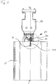
- FIG Figures 1 to 3 The basic structure of a securing device 20 according to the invention on a construction machine 10 is shown in FIG Figures 1 to 3 shown.
- the construction machine 10 which is only partially shown, has a ram drive unit 12, which can have imbalances that can be driven in rotation in a basically known manner.
- a hydraulic clamping device 13 is arranged on a lower region of the ram drive unit 12, with which a civil engineering element 5, which in the illustrated embodiment is a sheet pile wall, can be firmly clamped between two clamping jaws.
- a first insertion flank 14 and a second insertion flank 15 are arranged at the lower end of the ram drive unit 12, which together form an approximately V-shaped receiving slot.
- a securing device 20 according to the invention is provided for additionally securing the position of the civil engineering element 5.
- the securing device 20 comprises a flexible securing element 22, which is designed as a chain in the illustrated embodiment.
- a first end of the chain is fastened to the first insertion flank 14 and thus to the construction machine 10 by means of a plate-shaped fastening element 28.
- An insulating layer 29 can be arranged between the fastening element 28 and the first insertion flank 14, with which the fastening element 28 and thus the flexible securing element 22 is electrically insulated from the construction machine 10.
- a connecting member 24 is attached, which is designed as an approximately T-shaped toggle.
- the connecting member 24 can be pushed through a through hole or a securing eyelet 7 on the plank-shaped civil engineering element 5 and guided to a connecting device 30 on the second insertion flank 15, as illustrated in FIG Figures 2 and 3 is shown.
- the connecting member 24 can be introduced or pushed into a suitable slot-shaped receptacle 32 on the box-shaped connecting device 30, wherein the connecting member 24 can be locked in the connecting device 30.
- the box-shaped connector 30 in a receiving state is in the Figures 4 and 5 shown.
- a block-like housing 31 has a slot-like receptacle 32 for receiving the connecting member 24.
- the receptacle 32 is open on one side which faces away from the clamped civil engineering element 5.
- a slot 33 is made on an underside of the housing 31, the slot width of which is smaller than the receiving area of the receptacle 32 located above it.
- Two lateral, rail-like supports 35 are formed, which serve to place the toggle-shaped connecting member 24 on.
- the supports 35 can be designed with an upwardly projecting shoulder 37.
- a proximity sensor 42 is introduced as a detector unit 40 into a corresponding receiving bore.
- the proximity sensor 42 is designed to detect the presence of the connecting link 24 in the receptacle 32 of the connecting device 30.
- a vertically displaceable locking bolt 34 with an upper actuating plate 36 protrudes from a receiving bore on the upper side of the housing 31.
- the locking bolt 34 with the actuating plate 36 is designed for mechanical operation by hand or by means of an actuating tool.
- an active device (not shown), in particular an actuator such as a pneumatic or hydraulic actuator cylinder, can be provided.
- Fig. 6 the state of the securing device 20 is shown in which the T-shaped connecting link 24 of the chain-shaped flexible securing element 22 is inserted into the receptacle 32 of the connecting device 30.
- the locking bolt 34 is adjusted downward from a retracted position into a locking position. In this position, both the presence of the connecting link 24 in the connecting device 30 and an adjustment of the locking bolt 34 into the locking position can be determined by the detector unit 40 with the proximity sensor 42.
- the detector unit 40 can send a signal to a control unit, which signals that the connecting member 24 is correctly attached in the connecting device 30 and that the civil engineering element 5 is thus correctly secured by the flexible securing element 22.
Landscapes
- Engineering & Computer Science (AREA)
- General Engineering & Computer Science (AREA)
- Structural Engineering (AREA)
- Life Sciences & Earth Sciences (AREA)
- General Life Sciences & Earth Sciences (AREA)
- Mining & Mineral Resources (AREA)
- Paleontology (AREA)
- Civil Engineering (AREA)
- Placing Or Removing Of Piles Or Sheet Piles, Or Accessories Thereof (AREA)
Priority Applications (4)
| Application Number | Priority Date | Filing Date | Title |
|---|---|---|---|
| EP19162495.6A EP3708714B1 (fr) | 2019-03-13 | 2019-03-13 | Dispositif de fixation permettant de fixer un élément de génie civil et procédé de génie civil |
| AU2020201592A AU2020201592B2 (en) | 2019-03-13 | 2020-03-04 | Securing means for securing a civil engineering element, and civil engineering method |
| US16/815,143 US11174613B2 (en) | 2019-03-13 | 2020-03-11 | Securing means for securing a civil engineering element, and civil engineering method |
| CN202010176770.7A CN111691422B (zh) | 2019-03-13 | 2020-03-13 | 用于固定土木工程元件的固定器件和土木工程方法 |
Applications Claiming Priority (1)
| Application Number | Priority Date | Filing Date | Title |
|---|---|---|---|
| EP19162495.6A EP3708714B1 (fr) | 2019-03-13 | 2019-03-13 | Dispositif de fixation permettant de fixer un élément de génie civil et procédé de génie civil |
Publications (2)
| Publication Number | Publication Date |
|---|---|
| EP3708714A1 true EP3708714A1 (fr) | 2020-09-16 |
| EP3708714B1 EP3708714B1 (fr) | 2021-01-13 |
Family
ID=65801981
Family Applications (1)
| Application Number | Title | Priority Date | Filing Date |
|---|---|---|---|
| EP19162495.6A Active EP3708714B1 (fr) | 2019-03-13 | 2019-03-13 | Dispositif de fixation permettant de fixer un élément de génie civil et procédé de génie civil |
Country Status (4)
| Country | Link |
|---|---|
| US (1) | US11174613B2 (fr) |
| EP (1) | EP3708714B1 (fr) |
| CN (1) | CN111691422B (fr) |
| AU (1) | AU2020201592B2 (fr) |
Cited By (2)
| Publication number | Priority date | Publication date | Assignee | Title |
|---|---|---|---|---|
| EP4467723A1 (fr) | 2023-05-24 | 2024-11-27 | RTG Rammtechnik GmbH | Dispositif d'introduction pour introduire un élément de fondation |
| EP4671449A1 (fr) | 2024-06-26 | 2025-12-31 | ABI Anlagentechnik-Baumaschinen-Industriebedarf Maschinenfabrik und Vertriebsgesellschaft mbH | Dispositif et procédé de sécurisation d'un élément de construction souterraine sur une machine de construction souterraine |
Citations (7)
| Publication number | Priority date | Publication date | Assignee | Title |
|---|---|---|---|---|
| DE3602609A1 (de) | 1986-01-29 | 1987-07-30 | Sebastian Hofmann | Vorrichtung zum halten und einfuehren eines bauprofils in eine klemmvorrichtung |
| DE9318190U1 (de) * | 1993-11-27 | 1994-01-27 | Bilfinger + Berger Bauaktiengesellschaft, 68165 Mannheim | Rammvorrichtung für Rammbohlen, insbesondere Spundwandbohlen |
| US5332047A (en) | 1992-10-01 | 1994-07-26 | John Marino | Pile driving apparatus and method |
| US20020063245A1 (en) * | 2000-11-30 | 2002-05-30 | Salman Mark T. | Post puller |
| DE10322207A1 (de) * | 2003-05-16 | 2004-12-30 | Dr.Ing.H.C. F. Porsche Ag | Verfahren zur Ausgabe eines Signals einer Sicherheitsgurt-Warneinrichtung |
| EP3000942A1 (fr) * | 2014-09-25 | 2016-03-30 | BAUER Maschinen GmbH | Appareil de battage et procédé de battage d'un élément de pieu dans le sol |
| EP3228392A1 (fr) * | 2016-04-05 | 2017-10-11 | BAUER Maschinen GmbH | Appareil de battage a vibrations |
Family Cites Families (13)
| Publication number | Priority date | Publication date | Assignee | Title |
|---|---|---|---|---|
| DE3911646A1 (de) * | 1989-04-10 | 1990-10-11 | Anlagentech Baumasch Ind | Einfaedelvorrichtung zum einfuehren eines rammprofiles in eine klemmvorrichtung |
| US5353482A (en) | 1993-03-31 | 1994-10-11 | Ziaylek Theodore Jun | Releasable latching apparatus with an electrical engagement monitoring means |
| NL1005236C2 (nl) * | 1997-02-10 | 1998-08-11 | Hollandsche Betongroep Nv | Installatie voor het verwijderen van ingeheide voorwerpen. |
| DE19715133B4 (de) | 1997-04-11 | 2014-03-27 | TAKATA Aktiengesellschaft | Gurtschloß |
| US5966784A (en) | 1997-07-25 | 1999-10-19 | Trw Inc. | Method and apparatus for indicating the locked or unlocked condition of a seat belt buckle |
| DE19931977A1 (de) * | 1999-07-09 | 2001-04-19 | Peter Loster | Vorrichtung zum Feststellen von Schloßsprüngen an Spundwandbohlen, Pfählen und dergleichen |
| JP3458351B2 (ja) | 1999-09-21 | 2003-10-20 | タカタ株式会社 | バックル |
| CN201890755U (zh) | 2010-11-29 | 2011-07-06 | 广西玉柴重工有限公司 | 一种链条失效感应机构 |
| WO2014169917A1 (fr) * | 2013-04-19 | 2014-10-23 | Fractum 2012 Aps | Dispositif de martelage et procédé pour faire fonctionner un dispositif de martelage |
| NL2011001C2 (en) * | 2013-06-18 | 2014-12-22 | Ihc Hydrohammer B V | Method of and driver for installing foundation elements in a ground formation. |
| CN105271082A (zh) | 2014-07-25 | 2016-01-27 | 徐秀萍 | 一种工程机械自行式高空作业动臂连接机构 |
| CN107165167A (zh) * | 2017-06-19 | 2017-09-15 | 上海衡拓船舶设备有限公司 | 海上打桩用抱桩器 |
| EP3502353B1 (fr) * | 2017-12-22 | 2021-04-21 | Siemens Gamesa Renewable Energy A/S | Système de construction de fondations pour une éolienne offshore et procédé d'installation d'une éolienne offshore |
-
2019
- 2019-03-13 EP EP19162495.6A patent/EP3708714B1/fr active Active
-
2020
- 2020-03-04 AU AU2020201592A patent/AU2020201592B2/en active Active
- 2020-03-11 US US16/815,143 patent/US11174613B2/en active Active
- 2020-03-13 CN CN202010176770.7A patent/CN111691422B/zh active Active
Patent Citations (7)
| Publication number | Priority date | Publication date | Assignee | Title |
|---|---|---|---|---|
| DE3602609A1 (de) | 1986-01-29 | 1987-07-30 | Sebastian Hofmann | Vorrichtung zum halten und einfuehren eines bauprofils in eine klemmvorrichtung |
| US5332047A (en) | 1992-10-01 | 1994-07-26 | John Marino | Pile driving apparatus and method |
| DE9318190U1 (de) * | 1993-11-27 | 1994-01-27 | Bilfinger + Berger Bauaktiengesellschaft, 68165 Mannheim | Rammvorrichtung für Rammbohlen, insbesondere Spundwandbohlen |
| US20020063245A1 (en) * | 2000-11-30 | 2002-05-30 | Salman Mark T. | Post puller |
| DE10322207A1 (de) * | 2003-05-16 | 2004-12-30 | Dr.Ing.H.C. F. Porsche Ag | Verfahren zur Ausgabe eines Signals einer Sicherheitsgurt-Warneinrichtung |
| EP3000942A1 (fr) * | 2014-09-25 | 2016-03-30 | BAUER Maschinen GmbH | Appareil de battage et procédé de battage d'un élément de pieu dans le sol |
| EP3228392A1 (fr) * | 2016-04-05 | 2017-10-11 | BAUER Maschinen GmbH | Appareil de battage a vibrations |
Cited By (2)
| Publication number | Priority date | Publication date | Assignee | Title |
|---|---|---|---|---|
| EP4467723A1 (fr) | 2023-05-24 | 2024-11-27 | RTG Rammtechnik GmbH | Dispositif d'introduction pour introduire un élément de fondation |
| EP4671449A1 (fr) | 2024-06-26 | 2025-12-31 | ABI Anlagentechnik-Baumaschinen-Industriebedarf Maschinenfabrik und Vertriebsgesellschaft mbH | Dispositif et procédé de sécurisation d'un élément de construction souterraine sur une machine de construction souterraine |
Also Published As
| Publication number | Publication date |
|---|---|
| AU2020201592A1 (en) | 2020-10-01 |
| US20200291595A1 (en) | 2020-09-17 |
| US11174613B2 (en) | 2021-11-16 |
| EP3708714B1 (fr) | 2021-01-13 |
| CN111691422B (zh) | 2022-04-08 |
| CN111691422A (zh) | 2020-09-22 |
| AU2020201592B2 (en) | 2021-04-15 |
Similar Documents
| Publication | Publication Date | Title |
|---|---|---|
| EP3705629B1 (fr) | Dispositif de battage et procédé de battage dans un sol | |
| EP2489823B1 (fr) | Dispositif de séparation de matériaux solides | |
| KR101723512B1 (ko) | 천공 및 항타 겸용 파일 시공 장치 | |
| EP3708714B1 (fr) | Dispositif de fixation permettant de fixer un élément de génie civil et procédé de génie civil | |
| EP2920369A1 (fr) | Frein à déchirement | |
| EP2902582B2 (fr) | Système de mât et procédé de fixation d'un outil de travail au rail de coulissage du mât | |
| EP3670753B1 (fr) | Dispositif de battage et procédé de battage de pieux | |
| EP3369864A1 (fr) | Procédé de détection d'obstacles lors du fonctionnement d'un vibrateur de battage | |
| EP4279659A1 (fr) | Appareil d'excavation de tranchées pour parois moulées et procédé d'excavation d'une paroi moulée dans le sol | |
| DE69928848T2 (de) | Verfahren und Vorrichtung zur Herstellung von Grundpfählen mit erweiterten Pfahlköpfen | |
| EP2530205B1 (fr) | Procédé de pose verticale d'un tuyau et dispositif d'armature pour ce faire | |
| DE3615596A1 (de) | Verfahren und vorrichtung zum einbringen von pfaehlen oder dergleichen in den erdboden, bei dem die pfaehle in den erdboden eingepresst werden | |
| DE102017128887A1 (de) | Verfahren und Vorrichtung für die Sicherung einer Grube oder eines Grabens | |
| EP4047136A1 (fr) | Dispositif et procédé d'enfoncement de pieux par battage dans le sol | |
| DE102016014905B3 (de) | Werkzeugadapter mit einer Vorrichtung zur Verriegelungskontrolle einer Schnellwechselvorrichtung für Baugeräte | |
| DE2355232A1 (de) | Strassenaufbruchgeraet zum aufbrechen von strassendecken | |
| EP0237971B1 (fr) | Appareil pour enfoncer et/ou extraire un profilé de construction | |
| DE216258C (fr) | ||
| DE3304268C2 (fr) | ||
| DE4303742C1 (de) | Verfahren zur Entwässerung von Böden mit hohem Wasseranteil | |
| EP4506507B1 (fr) | Dispositif de génie civil et procédé de fonctionnement d'un dispositif de génie civil | |
| DE1634529B2 (de) | Verfahren zum Herstellen von Bgdenschlitzen für Schlitzwände | |
| DE19755228C2 (de) | Vorrichtung zum Einbringen eines länglichen Profils in den Untergrund | |
| EP4671449A1 (fr) | Dispositif et procédé de sécurisation d'un élément de construction souterraine sur une machine de construction souterraine | |
| DE102005044104B3 (de) | Verfahren zum Kappen eines oberen Endes eines Gründungselementes |
Legal Events
| Date | Code | Title | Description |
|---|---|---|---|
| PUAI | Public reference made under article 153(3) epc to a published international application that has entered the european phase |
Free format text: ORIGINAL CODE: 0009012 |
|
| STAA | Information on the status of an ep patent application or granted ep patent |
Free format text: STATUS: REQUEST FOR EXAMINATION WAS MADE |
|
| 17P | Request for examination filed |
Effective date: 20191001 |
|
| AK | Designated contracting states |
Kind code of ref document: A1 Designated state(s): AL AT BE BG CH CY CZ DE DK EE ES FI FR GB GR HR HU IE IS IT LI LT LU LV MC MK MT NL NO PL PT RO RS SE SI SK SM TR |
|
| AX | Request for extension of the european patent |
Extension state: BA ME |
|
| GRAP | Despatch of communication of intention to grant a patent |
Free format text: ORIGINAL CODE: EPIDOSNIGR1 |
|
| STAA | Information on the status of an ep patent application or granted ep patent |
Free format text: STATUS: GRANT OF PATENT IS INTENDED |
|
| INTG | Intention to grant announced |
Effective date: 20201008 |
|
| GRAS | Grant fee paid |
Free format text: ORIGINAL CODE: EPIDOSNIGR3 |
|
| GRAA | (expected) grant |
Free format text: ORIGINAL CODE: 0009210 |
|
| STAA | Information on the status of an ep patent application or granted ep patent |
Free format text: STATUS: THE PATENT HAS BEEN GRANTED |
|
| AK | Designated contracting states |
Kind code of ref document: B1 Designated state(s): AL AT BE BG CH CY CZ DE DK EE ES FI FR GB GR HR HU IE IS IT LI LT LU LV MC MK MT NL NO PL PT RO RS SE SI SK SM TR |
|
| REG | Reference to a national code |
Ref country code: GB Ref legal event code: FG4D Free format text: NOT ENGLISH |
|
| REG | Reference to a national code |
Ref country code: CH Ref legal event code: EP |
|
| REG | Reference to a national code |
Ref country code: DE Ref legal event code: R096 Ref document number: 502019000666 Country of ref document: DE |
|
| REG | Reference to a national code |
Ref country code: IE Ref legal event code: FG4D Free format text: LANGUAGE OF EP DOCUMENT: GERMAN |
|
| GRAT | Correction requested after decision to grant or after decision to maintain patent in amended form |
Free format text: ORIGINAL CODE: EPIDOSNCDEC |
|
| REG | Reference to a national code |
Ref country code: AT Ref legal event code: REF Ref document number: 1354653 Country of ref document: AT Kind code of ref document: T Effective date: 20210215 |
|
| REG | Reference to a national code |
Ref country code: NL Ref legal event code: FP |
|
| REG | Reference to a national code |
Ref country code: FI Ref legal event code: FGE |
|
| REG | Reference to a national code |
Ref country code: LT Ref legal event code: MG9D |
|
| PG25 | Lapsed in a contracting state [announced via postgrant information from national office to epo] |
Ref country code: NO Free format text: LAPSE BECAUSE OF FAILURE TO SUBMIT A TRANSLATION OF THE DESCRIPTION OR TO PAY THE FEE WITHIN THE PRESCRIBED TIME-LIMIT Effective date: 20210413 Ref country code: PT Free format text: LAPSE BECAUSE OF FAILURE TO SUBMIT A TRANSLATION OF THE DESCRIPTION OR TO PAY THE FEE WITHIN THE PRESCRIBED TIME-LIMIT Effective date: 20210513 Ref country code: LT Free format text: LAPSE BECAUSE OF FAILURE TO SUBMIT A TRANSLATION OF THE DESCRIPTION OR TO PAY THE FEE WITHIN THE PRESCRIBED TIME-LIMIT Effective date: 20210113 Ref country code: GR Free format text: LAPSE BECAUSE OF FAILURE TO SUBMIT A TRANSLATION OF THE DESCRIPTION OR TO PAY THE FEE WITHIN THE PRESCRIBED TIME-LIMIT Effective date: 20210414 Ref country code: HR Free format text: LAPSE BECAUSE OF FAILURE TO SUBMIT A TRANSLATION OF THE DESCRIPTION OR TO PAY THE FEE WITHIN THE PRESCRIBED TIME-LIMIT Effective date: 20210113 Ref country code: BG Free format text: LAPSE BECAUSE OF FAILURE TO SUBMIT A TRANSLATION OF THE DESCRIPTION OR TO PAY THE FEE WITHIN THE PRESCRIBED TIME-LIMIT Effective date: 20210413 |
|
| PG25 | Lapsed in a contracting state [announced via postgrant information from national office to epo] |
Ref country code: SE Free format text: LAPSE BECAUSE OF FAILURE TO SUBMIT A TRANSLATION OF THE DESCRIPTION OR TO PAY THE FEE WITHIN THE PRESCRIBED TIME-LIMIT Effective date: 20210113 Ref country code: PL Free format text: LAPSE BECAUSE OF FAILURE TO SUBMIT A TRANSLATION OF THE DESCRIPTION OR TO PAY THE FEE WITHIN THE PRESCRIBED TIME-LIMIT Effective date: 20210113 Ref country code: RS Free format text: LAPSE BECAUSE OF FAILURE TO SUBMIT A TRANSLATION OF THE DESCRIPTION OR TO PAY THE FEE WITHIN THE PRESCRIBED TIME-LIMIT Effective date: 20210113 Ref country code: LV Free format text: LAPSE BECAUSE OF FAILURE TO SUBMIT A TRANSLATION OF THE DESCRIPTION OR TO PAY THE FEE WITHIN THE PRESCRIBED TIME-LIMIT Effective date: 20210113 |
|
| PG25 | Lapsed in a contracting state [announced via postgrant information from national office to epo] |
Ref country code: IS Free format text: LAPSE BECAUSE OF FAILURE TO SUBMIT A TRANSLATION OF THE DESCRIPTION OR TO PAY THE FEE WITHIN THE PRESCRIBED TIME-LIMIT Effective date: 20210513 |
|
| REG | Reference to a national code |
Ref country code: DE Ref legal event code: R026 Ref document number: 502019000666 Country of ref document: DE |
|
| PLBI | Opposition filed |
Free format text: ORIGINAL CODE: 0009260 |
|
| PG25 | Lapsed in a contracting state [announced via postgrant information from national office to epo] |
Ref country code: MC Free format text: LAPSE BECAUSE OF FAILURE TO SUBMIT A TRANSLATION OF THE DESCRIPTION OR TO PAY THE FEE WITHIN THE PRESCRIBED TIME-LIMIT Effective date: 20210113 Ref country code: EE Free format text: LAPSE BECAUSE OF FAILURE TO SUBMIT A TRANSLATION OF THE DESCRIPTION OR TO PAY THE FEE WITHIN THE PRESCRIBED TIME-LIMIT Effective date: 20210113 Ref country code: CZ Free format text: LAPSE BECAUSE OF FAILURE TO SUBMIT A TRANSLATION OF THE DESCRIPTION OR TO PAY THE FEE WITHIN THE PRESCRIBED TIME-LIMIT Effective date: 20210113 Ref country code: SM Free format text: LAPSE BECAUSE OF FAILURE TO SUBMIT A TRANSLATION OF THE DESCRIPTION OR TO PAY THE FEE WITHIN THE PRESCRIBED TIME-LIMIT Effective date: 20210113 |
|
| PLAX | Notice of opposition and request to file observation + time limit sent |
Free format text: ORIGINAL CODE: EPIDOSNOBS2 |
|
| REG | Reference to a national code |
Ref country code: FI Ref legal event code: MDE Opponent name: LIEBHERR-WERK NENZING GMBH |
|
| 26 | Opposition filed |
Opponent name: LIEBHERR-WERK NENZING GMBH Effective date: 20211013 |
|
| PG25 | Lapsed in a contracting state [announced via postgrant information from national office to epo] |
Ref country code: DK Free format text: LAPSE BECAUSE OF FAILURE TO SUBMIT A TRANSLATION OF THE DESCRIPTION OR TO PAY THE FEE WITHIN THE PRESCRIBED TIME-LIMIT Effective date: 20210113 Ref country code: SK Free format text: LAPSE BECAUSE OF FAILURE TO SUBMIT A TRANSLATION OF THE DESCRIPTION OR TO PAY THE FEE WITHIN THE PRESCRIBED TIME-LIMIT Effective date: 20210113 Ref country code: RO Free format text: LAPSE BECAUSE OF FAILURE TO SUBMIT A TRANSLATION OF THE DESCRIPTION OR TO PAY THE FEE WITHIN THE PRESCRIBED TIME-LIMIT Effective date: 20210113 |
|
| REG | Reference to a national code |
Ref country code: BE Ref legal event code: MM Effective date: 20210331 |
|
| PG25 | Lapsed in a contracting state [announced via postgrant information from national office to epo] |
Ref country code: AL Free format text: LAPSE BECAUSE OF FAILURE TO SUBMIT A TRANSLATION OF THE DESCRIPTION OR TO PAY THE FEE WITHIN THE PRESCRIBED TIME-LIMIT Effective date: 20210113 Ref country code: IE Free format text: LAPSE BECAUSE OF NON-PAYMENT OF DUE FEES Effective date: 20210313 Ref country code: LU Free format text: LAPSE BECAUSE OF NON-PAYMENT OF DUE FEES Effective date: 20210313 Ref country code: ES Free format text: LAPSE BECAUSE OF FAILURE TO SUBMIT A TRANSLATION OF THE DESCRIPTION OR TO PAY THE FEE WITHIN THE PRESCRIBED TIME-LIMIT Effective date: 20210113 |
|
| PLBB | Reply of patent proprietor to notice(s) of opposition received |
Free format text: ORIGINAL CODE: EPIDOSNOBS3 |
|
| PG25 | Lapsed in a contracting state [announced via postgrant information from national office to epo] |
Ref country code: IT Free format text: LAPSE BECAUSE OF FAILURE TO SUBMIT A TRANSLATION OF THE DESCRIPTION OR TO PAY THE FEE WITHIN THE PRESCRIBED TIME-LIMIT Effective date: 20210113 |
|
| PG25 | Lapsed in a contracting state [announced via postgrant information from national office to epo] |
Ref country code: IS Free format text: LAPSE BECAUSE OF FAILURE TO SUBMIT A TRANSLATION OF THE DESCRIPTION OR TO PAY THE FEE WITHIN THE PRESCRIBED TIME-LIMIT Effective date: 20210513 |
|
| PG25 | Lapsed in a contracting state [announced via postgrant information from national office to epo] |
Ref country code: BE Free format text: LAPSE BECAUSE OF NON-PAYMENT OF DUE FEES Effective date: 20210331 |
|
| REG | Reference to a national code |
Ref country code: CH Ref legal event code: PL |
|
| PG25 | Lapsed in a contracting state [announced via postgrant information from national office to epo] |
Ref country code: LI Free format text: LAPSE BECAUSE OF NON-PAYMENT OF DUE FEES Effective date: 20220331 Ref country code: CH Free format text: LAPSE BECAUSE OF NON-PAYMENT OF DUE FEES Effective date: 20220331 |
|
| PG25 | Lapsed in a contracting state [announced via postgrant information from national office to epo] |
Ref country code: CY Free format text: LAPSE BECAUSE OF FAILURE TO SUBMIT A TRANSLATION OF THE DESCRIPTION OR TO PAY THE FEE WITHIN THE PRESCRIBED TIME-LIMIT Effective date: 20210113 |
|
| PG25 | Lapsed in a contracting state [announced via postgrant information from national office to epo] |
Ref country code: SI Free format text: LAPSE BECAUSE OF FAILURE TO SUBMIT A TRANSLATION OF THE DESCRIPTION OR TO PAY THE FEE WITHIN THE PRESCRIBED TIME-LIMIT Effective date: 20210113 Ref country code: HU Free format text: LAPSE BECAUSE OF FAILURE TO SUBMIT A TRANSLATION OF THE DESCRIPTION OR TO PAY THE FEE WITHIN THE PRESCRIBED TIME-LIMIT; INVALID AB INITIO Effective date: 20190313 |
|
| PLCK | Communication despatched that opposition was rejected |
Free format text: ORIGINAL CODE: EPIDOSNREJ1 |
|
| APBM | Appeal reference recorded |
Free format text: ORIGINAL CODE: EPIDOSNREFNO |
|
| APBP | Date of receipt of notice of appeal recorded |
Free format text: ORIGINAL CODE: EPIDOSNNOA2O |
|
| APAH | Appeal reference modified |
Free format text: ORIGINAL CODE: EPIDOSCREFNO |
|
| PG25 | Lapsed in a contracting state [announced via postgrant information from national office to epo] |
Ref country code: MK Free format text: LAPSE BECAUSE OF FAILURE TO SUBMIT A TRANSLATION OF THE DESCRIPTION OR TO PAY THE FEE WITHIN THE PRESCRIBED TIME-LIMIT Effective date: 20210113 |
|
| APBQ | Date of receipt of statement of grounds of appeal recorded |
Free format text: ORIGINAL CODE: EPIDOSNNOA3O |
|
| PG25 | Lapsed in a contracting state [announced via postgrant information from national office to epo] |
Ref country code: TR Free format text: LAPSE BECAUSE OF FAILURE TO SUBMIT A TRANSLATION OF THE DESCRIPTION OR TO PAY THE FEE WITHIN THE PRESCRIBED TIME-LIMIT Effective date: 20210113 |
|
| PG25 | Lapsed in a contracting state [announced via postgrant information from national office to epo] |
Ref country code: MT Free format text: LAPSE BECAUSE OF FAILURE TO SUBMIT A TRANSLATION OF THE DESCRIPTION OR TO PAY THE FEE WITHIN THE PRESCRIBED TIME-LIMIT Effective date: 20210113 |
|
| P01 | Opt-out of the competence of the unified patent court (upc) registered |
Free format text: CASE NUMBER: UPC_APP_119899/2023 Effective date: 20230510 |
|
| PLAB | Opposition data, opponent's data or that of the opponent's representative modified |
Free format text: ORIGINAL CODE: 0009299OPPO |
|
| REG | Reference to a national code |
Ref country code: CH Ref legal event code: L10 Free format text: ST27 STATUS EVENT CODE: U-0-0-L10-L00 (AS PROVIDED BY THE NATIONAL OFFICE) Effective date: 20251105 |
|
| R26 | Opposition filed (corrected) |
Opponent name: LIEBHERR-WERK NENZING GMBH Effective date: 20211013 |
|
| REG | Reference to a national code |
Ref country code: DE Ref legal event code: R100 Ref document number: 502019000666 Country of ref document: DE |
|
| APBU | Appeal procedure closed |
Free format text: ORIGINAL CODE: EPIDOSNNOA9O |
|
| PLBN | Opposition rejected |
Free format text: ORIGINAL CODE: 0009273 |
|
| STAA | Information on the status of an ep patent application or granted ep patent |
Free format text: STATUS: OPPOSITION REJECTED |
|
| REG | Reference to a national code |
Ref country code: CH Ref legal event code: L18 Free format text: ST27 STATUS EVENT CODE: U-0-0-L10-L18 (AS PROVIDED BY THE NATIONAL OFFICE) Effective date: 20260114 |
|
| 27O | Opposition rejected |
Effective date: 20251218 |
|
| PGFP | Annual fee paid to national office [announced via postgrant information from national office to epo] |
Ref country code: GB Payment date: 20260324 Year of fee payment: 8 |
|
| PGFP | Annual fee paid to national office [announced via postgrant information from national office to epo] |
Ref country code: DE Payment date: 20260320 Year of fee payment: 8 |
|
| PGFP | Annual fee paid to national office [announced via postgrant information from national office to epo] |
Ref country code: AT Payment date: 20260320 Year of fee payment: 8 |
|
| PGFP | Annual fee paid to national office [announced via postgrant information from national office to epo] |
Ref country code: FI Payment date: 20260317 Year of fee payment: 8 |
|
| PGFP | Annual fee paid to national office [announced via postgrant information from national office to epo] |
Ref country code: NL Payment date: 20260320 Year of fee payment: 8 |
|
| PGFP | Annual fee paid to national office [announced via postgrant information from national office to epo] |
Ref country code: FR Payment date: 20260327 Year of fee payment: 8 |