EP3708748A1 - Stangengriff für befestigungen - Google Patents
Stangengriff für befestigungen Download PDFInfo
- Publication number
- EP3708748A1 EP3708748A1 EP20161416.1A EP20161416A EP3708748A1 EP 3708748 A1 EP3708748 A1 EP 3708748A1 EP 20161416 A EP20161416 A EP 20161416A EP 3708748 A1 EP3708748 A1 EP 3708748A1
- Authority
- EP
- European Patent Office
- Prior art keywords
- cogwheel
- fixing base
- rod
- handle
- gripping handle
- Prior art date
- Legal status (The legal status is an assumption and is not a legal conclusion. Google has not performed a legal analysis and makes no representation as to the accuracy of the status listed.)
- Granted
Links
Images



Classifications
-
- E—FIXED CONSTRUCTIONS
- E05—LOCKS; KEYS; WINDOW OR DOOR FITTINGS; SAFES
- E05C—BOLTS OR FASTENING DEVICES FOR WINGS, SPECIALLY FOR DOORS OR WINDOWS
- E05C9/00—Arrangements of simultaneously actuated bolts or other securing devices at well-separated positions on the same wing
- E05C9/04—Arrangements of simultaneously actuated bolts or other securing devices at well-separated positions on the same wing with two sliding bars moved in opposite directions when fastening or unfastening
- E05C9/041—Arrangements of simultaneously actuated bolts or other securing devices at well-separated positions on the same wing with two sliding bars moved in opposite directions when fastening or unfastening with rack and pinion mechanism
-
- E—FIXED CONSTRUCTIONS
- E05—LOCKS; KEYS; WINDOW OR DOOR FITTINGS; SAFES
- E05B—LOCKS; ACCESSORIES THEREFOR; HANDCUFFS
- E05B65/00—Locks or fastenings for special use
- E05B65/0025—Locks or fastenings for special use for glass wings
-
- E—FIXED CONSTRUCTIONS
- E05—LOCKS; KEYS; WINDOW OR DOOR FITTINGS; SAFES
- E05B—LOCKS; ACCESSORIES THEREFOR; HANDCUFFS
- E05B7/00—Handles pivoted about an axis parallel to the wing
-
- E—FIXED CONSTRUCTIONS
- E05—LOCKS; KEYS; WINDOW OR DOOR FITTINGS; SAFES
- E05B—LOCKS; ACCESSORIES THEREFOR; HANDCUFFS
- E05B15/00—Other details of locks; Parts for engagement by bolts of fastening devices
- E05B15/02—Striking-plates; Keepers; Bolt staples; Escutcheons
Definitions
- the present invention relates to a rod handle for fixtures, in particular for windows.
- a rod handle is a device attached to a fixture in order to operate movement rods of a closing system of the fixture.
- the movement rods can be arranged on the outside of the structure of the fixture or can be housed inside said structure.
- a rod handle comprises:
- the kinematic connection mechanism between the gripping handle and movement rods comprises:
- the cogwheel and the two operating rods form a rack-pinion system.
- a rotational movement of the cogwheel requires the two rods to move in parallel with the fixing base and with one another, in opposite directions.
- the cogwheel is rotationally integral to the gripping handle by means of a prismatic axial coupling.
- a rotational movement of the gripping handle corresponds to a rotational movement of the cogwheel of the same angular width and therefore to a predefined translational movement stroke of the two operating rods.
- the cogwheel In order to ensure stable meshing between the cogwheel and operating rods and, at the same time, impose the required stroke on the two rods by means of a rotational movement of the gripping handle having an angular width that is operatively permissible for manual operation (between 90° and 180°), the cogwheel has to have a minimum nominal diameter. This imposes minimal dimensions in the transverse direction on the fixing base of the handle so as to be able to house the cogwheel and the two rods.
- the "transverse direction” means the plan dimension that is orthogonal to the longitudinal direction, in parallel with which the two rods move. This bond affects the dimensions of the profiles that form the frame of the fixture and those the handle has to be attached to by means of the relative fixing base.
- 1 indicates, as a whole, a rod handle for fixtures as per the present invention.
- the handle 1 according to the invention is in particular intended to be attached to windows (sliding or casement windows), but can generally also be attached to other types of fixtures, for example door fixtures, French doors or front door fixtures.
- the rod handle 1 comprises a fixing base 2 that is intended to be rigidly fixed to a fixture (not shown in the attached drawings).
- the fixing base 2 is intended to be fixed to a profiled portion that forms the frame of the window.
- the fixing base 2 extends in plan in a longitudinal direction X-X and in a transverse direction Y-Y, which is orthogonal to said longitudinal direction X-X.
- Plant extension means the extension of the portion of the fixing base that is intended to rest against the fixture.
- the attachment of a handle 1 to a fixture is influenced by the transverse dimensions of the fixing base, which may not be greater than those of the fixture portion intended to receive the handle.
- the fixing base 2 can be made up of a plate, preferably in metal material.
- the fixing base 2 can be provided with a plurality of through-holes for inserting anchoring elements into the fixture, for example screws or bolts.
- the handle 1 comprises:
- the first operating rod 11 can move in a translational manner with respect to the fixing base 2 in parallel with said longitudinal direction X-X following rotational movements of the cogwheel 10 about its axis of rotation Z1-Z1.
- this first operating rod 11 is intended to be connected to a closing system of a fixture (not shown in the attached drawings) in order to operate it by means of its translational movements.
- the handle 1 also comprises a gripping handle 20, which is rotationally moveable with respect to the fixing base 2 between a first angular position and a second angular position and is kinematically connected to the cogwheel 10 in order to drag the cogwheel 10 in rotation as it passes between said two angular positions.
- the rotational movement of the cogwheel causes the translational movement of the first movement rod between two different longitudinal positions, in which the closing system is operated such that it closes and opens, respectively.
- the handle 1 may comprise just one operating rod. In terms of operation, in this case, the handle 1 can only act on the closing system of the fixture from one point only.
- the handle 1 comprises two operating rods 11, 12, both of which mesh with the cogwheel 10.
- the handle 1 comprises a second operating rod 12 in addition to said first operating rod 11.
- the handle 1 can act on the closing system of the fixture from two different points.
- a toothed portion 12a of this second operating rod 12 meshes with the cogwheel 10 in a position that is transversally opposite the first rod 11.
- This second operating rod 11 is also:
- Said first and second operating rods 11, 12 form a pinion-double rack system together with said cogwheel 10.
- the cogwheel 1 and the two operating rods 11, 12t have overall transverse plan dimensions not greater than the transverse extension of the fixing base 2. This is also applicable when the handle 1 comprises a single operating rod.
- each of said two operating rods 11, 12 comprises an appendage 11b, 12b that extends orthogonally with respect to the fixing base 2 (on the opposite side to the side where said cogwheel 10 is rotationally associated) and passes through the base 2 via a respective through-hole for longitudinal sliding 3, 4.
- Each operating rod 11, 12 is intended to connect to the closing system of a fixture by means of the respective appendage 11b, 12b. This configuration is also provided when the handle 1 comprises just one operating rod.
- the appendage 11b, 12b can be of any shape.
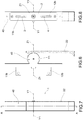
- it can be made up of a cylindrical body (as illustrated in Fig. 1 to 5 ) or of a plate (as illustrated in Fig. 6 to 10 ).
- the gripping handle 20 is kinematically connected to the cogwheel 10 by means of a bevel gear transmission system 31, 32, in which:
- rotationally integral referring to the driving bevel wheel with respect to the gripping handle means that the driving bevel wheel integrally rotates with the gripping handle about the same axis of rotation.
- the expression “rotationally integral” referring to the driven bevel wheel with respect to the cogwheel means that the driven bevel wheel integrally rotates with the cogwheel about the same axis of rotation.
- the driven bevel wheel 32 is made as one piece together with the cogwheel 10.
- the driving bevel wheel 31 and the associated gripping handle 20 are rotationally supported by a containment structure 40, which is in turn fixed to the fixing base 2.
- the driven bevel wheel 31 is instead rotationally supported by the cogwheel 10 that, as already mentioned, is in turn directly rotationally supported by the fixing base.
- the above-mentioned bevel gear system 31, 32 has a transmission ratio lower than 1 (multiplying ratio) such that to an angular rotation of the gripping handle 20 between said first and second angular position it corresponds an angular rotation of the cogwheel 10 having a greater width.
- the driving cogwheel 31 has a nominal diameter that is greater than the nominal diameter of the driven wheel 32.
- the bevel gear transmission system described above it is in particular possible to reduce the nominal diameter of the cogwheel 10 (and therefore to contain the transverse plan extension of the fixing base 2) without having to intervene with the width of the longitudinal stroke of the operating rod and/or with the width of the rotational movement of the gripping handle between the first and the second angular position.
- the reduction in the nominal diameter of the cogwheel 10 does not influence the extension of the longitudinal stroke of the rod since this reduction is compensated for by an increase in the width of the angular rotation of said cogwheel 10.
- a reduction in the nominal diameter of the cogwheel corresponds to a reduction in the number of teeth in said wheel and not to a reduction in all the dimensions of said teeth. This means that the reduction in the dimensions of the cogwheel does not jeopardize the meshing stability between the cogwheel and the rod, to the advantage of robustness and reliability of the handle 1.
- the above-mentioned bevel gear transmission system 31, 32 is arranged between the fixing base 2 and the gripping handle 20 and extends together with the driving bevel wheel 31 that substantially extends in the orthogonal and longitudinal direction with respect to the base 2 so as not to increase the transverse plan dimensions of the handle and therefore of the fixing base.
- the bevel gear transmission system 31, 32 in particular has the following features:
- the driving bevel wheel 31 is therefore arranged such that the diametric dimensions thereof do not affect the dimensions in the transverse direction, but only the dimensions in the orthogonal and longitudinal directions. In the transverse direction, the dimensions of the driving wheel 31 correspond to the height of the teeth thereof and therefore remain inside the transverse dimensions of the driven wheel 32.
- the bevel gear transmission system 31, 32 has overall transverse plan dimensions that are not greater than the transverse extension of the fixing base 2 and are not influenced by the nominal diameter of the driving bevel wheel 31.
- the two conical wheels 31 and 32 have teeth that are at a 45° angle.
- the gripping handle 20 is made up of a lever having a pivot and rotation axis that coincides with the axis of rotation Y1-Y1 of the driving bevel wheel 31. Therefore, in the preferred case in which the driving bevel wheel 31 is arranged so that its axis of rotation Y1-Y1 is parallel to said transverse direction Y-Y, the axis of rotation of the gripping handle 20 is also parallel to said transverse direction Y-Y.
- the gripping handle 20 with lever has transverse dimensions that are no greater than the transverse extension of the fixing base 2.
- this configuration of the gripping handle 20 is provided in the preferred embodiment in which the bevel gear transmission system has transverse dimensions that are no greater than the transverse plan dimension of the fixing base 2.
- the handle 1, included then also the gripping handle 20 has transverse plan dimensions that are not greater than the transverse plan extension of the fixing base 2.
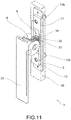
- the gripping handle 20 comprises a portion 21 of pivoting the containment structure 40 and a gripping portion 22, which is fixed to the pivoting portion.
- the gripping portion 22 is made separately from the pivoting portion 21 and its shape may differ depending on design requirements.
- the driving bevel wheel 31 is made in one piece with said pivoting portion 21 of the gripping handle 20.
- the driving bevel wheel 31 can be made separately and can be made integral with the pivoting portion 21 of the gripping handle 20 by means of one or more pins.
- the containment structure 40 is defined by a box-shaped body having an internal portion that is equivalent to the plan shape of the fixing base 2.
- the containment structure 40 is fixed to the fixing base 2 by means of shape coupling.
- the above-mentioned containment structure 40 is designed to delimit, together with the fixing base 2, a first chamber 5 in which the cogwheel 10 and the two operating rods 11, 12 are housed (or the single rod, if only one rod is provided).
- the containment structure 40 is also designed to delimit a second chamber 6, which is orthogonally superposed on the first chamber 5 and in which the bevel gear transmission system 31, 32 is housed.
- the first chamber 5 and the second chamber 6 communicate with one another to allow for the kinematic coupling between the cogwheel 10 and the driving bevel wheel 31.
- the gripping handle 20 preferably made up of a lever, is rotationally associated with said containment structure 40 in the second chamber 6. More specifically, the pivoting portion 21 of the gripping handle 20 is housed in the second chamber 6, while the gripping portion 22 protrudes from the second chamber 6.
- the invention makes it possible to achieve numerous advantages, some of which have already been described.
- the rod handle according to the invention can be made having smaller transverse dimensions with respect to those of known rod handles, without, however, losing functionality.
- the handle according to the invention can be made having reduced transverse dimensions without this involving an increase in the width of the rotation of the gripping handle, being the longitudinal stroke of the operating rods equal.
- the handle according to the invention can also be made having very limited transverse dimensions, thus combining reliability and robustness.
- the individual components that form the internal movement mechanism of the handle can in fact be made having reduced dimensions, without, however, losing rigidity.
- the invention designed in this way therefore achieves the predetermined objects.
Landscapes
- Engineering & Computer Science (AREA)
- Mechanical Engineering (AREA)
- Mechanically-Actuated Valves (AREA)
- Passenger Equipment (AREA)
- Vehicle Interior And Exterior Ornaments, Soundproofing, And Insulation (AREA)
- Lock And Its Accessories (AREA)
Applications Claiming Priority (1)
| Application Number | Priority Date | Filing Date | Title |
|---|---|---|---|
| IT102019000003557A IT201900003557A1 (it) | 2019-03-12 | 2019-03-12 | Maniglia a cariglione per infissi |
Publications (2)
| Publication Number | Publication Date |
|---|---|
| EP3708748A1 true EP3708748A1 (de) | 2020-09-16 |
| EP3708748B1 EP3708748B1 (de) | 2022-04-06 |
Family
ID=66776749
Family Applications (1)
| Application Number | Title | Priority Date | Filing Date |
|---|---|---|---|
| EP20161416.1A Active EP3708748B1 (de) | 2019-03-12 | 2020-03-06 | Stangengriff für befestigungen |
Country Status (2)
| Country | Link |
|---|---|
| EP (1) | EP3708748B1 (de) |
| IT (1) | IT201900003557A1 (de) |
Cited By (1)
| Publication number | Priority date | Publication date | Assignee | Title |
|---|---|---|---|---|
| CN112065200A (zh) * | 2020-09-30 | 2020-12-11 | 深圳市派阁智能五金科技有限公司 | 一种手拉式执手装置和内开内倒门窗系统 |
Families Citing this family (1)
| Publication number | Priority date | Publication date | Assignee | Title |
|---|---|---|---|---|
| CN114871042B (zh) * | 2022-01-24 | 2023-04-28 | 深圳市泰英通信工程有限公司 | 一种智慧城市小区花园智能风光音乐喷泉及测试方法 |
Citations (5)
| Publication number | Priority date | Publication date | Assignee | Title |
|---|---|---|---|---|
| GB921594A (en) * | 1961-02-02 | 1963-03-20 | Evered & Co Ltd | Improvements in and relating to door latches |
| WO2003031754A1 (en) * | 2001-10-11 | 2003-04-17 | Giovanni Palamara | Handling device for revolving doors, in particular window shutters |
| DE102004019256A1 (de) * | 2004-04-16 | 2005-11-03 | Dirak Dieter Ramsauer Konstruktionselemente Gmbh & Co. Kg | Stangenverschluß für Blechschranktüren |
| KR200426484Y1 (ko) * | 2006-06-07 | 2006-09-19 | 김용범 | 창문 잠금장치 |
| EP2267253A2 (de) * | 2009-06-25 | 2010-12-29 | Milgard Manufacturing Incorporated | Griff und Verriegelungsvorrichtung für eine Schiebetür |
-
2019
- 2019-03-12 IT IT102019000003557A patent/IT201900003557A1/it unknown
-
2020
- 2020-03-06 EP EP20161416.1A patent/EP3708748B1/de active Active
Patent Citations (5)
| Publication number | Priority date | Publication date | Assignee | Title |
|---|---|---|---|---|
| GB921594A (en) * | 1961-02-02 | 1963-03-20 | Evered & Co Ltd | Improvements in and relating to door latches |
| WO2003031754A1 (en) * | 2001-10-11 | 2003-04-17 | Giovanni Palamara | Handling device for revolving doors, in particular window shutters |
| DE102004019256A1 (de) * | 2004-04-16 | 2005-11-03 | Dirak Dieter Ramsauer Konstruktionselemente Gmbh & Co. Kg | Stangenverschluß für Blechschranktüren |
| KR200426484Y1 (ko) * | 2006-06-07 | 2006-09-19 | 김용범 | 창문 잠금장치 |
| EP2267253A2 (de) * | 2009-06-25 | 2010-12-29 | Milgard Manufacturing Incorporated | Griff und Verriegelungsvorrichtung für eine Schiebetür |
Cited By (1)
| Publication number | Priority date | Publication date | Assignee | Title |
|---|---|---|---|---|
| CN112065200A (zh) * | 2020-09-30 | 2020-12-11 | 深圳市派阁智能五金科技有限公司 | 一种手拉式执手装置和内开内倒门窗系统 |
Also Published As
| Publication number | Publication date |
|---|---|
| EP3708748B1 (de) | 2022-04-06 |
| IT201900003557A1 (it) | 2020-09-12 |
Similar Documents
| Publication | Publication Date | Title |
|---|---|---|
| EP3708748B1 (de) | Stangengriff für befestigungen | |
| AU2010285685B2 (en) | Damper position adjusting device | |
| JP4723013B2 (ja) | 位置調節機能付きカップ埋め込み式ヒンジ装置 | |
| ES2659375T3 (es) | Bisagra decelerada para mobiliario | |
| US8935887B2 (en) | Linear actuator particularly for sliding doors and for sliding doors and windows in general | |
| CA2119400C (en) | Sleeve actuator for a window or a door | |
| RU2000115728A (ru) | Петля для открывания дверной или оконной рамы | |
| CN107923432B (zh) | 合叶装置 | |
| US10451334B2 (en) | Left-right door opening mechanism and refrigerator | |
| JP2014515442A (ja) | ヒンジ | |
| KR20140065423A (ko) | 가구힌지용 가동형 취부판 | |
| WO2016128910A1 (en) | Hinge for doors or windows | |
| CN110714978A (zh) | 一种转动机构和柔性屏设备 | |
| ES2950019T3 (es) | Accionamiento de brazo de ajuste | |
| CN103867055A (zh) | 与锁定装置相关的改进 | |
| EP3680439B1 (de) | Bewegungssystem für eine verschlussstruktur mit faltbewegung | |
| CN110594547B (zh) | 折叠铰链及折叠显示装置 | |
| JP2004346732A (ja) | 扉付き骨格構造部材 | |
| GB2281097A (en) | A multi-point locking mechanism having locking members that move in opposite directions | |
| GB2054794A (en) | Adjustment mechanism | |
| CN211174980U (zh) | 一种转动机构和柔性屏设备 | |
| EP2853447B1 (de) | Farhzeug-Inneneinbauelement mit kippbarem Deckel | |
| EP1621707A1 (de) | Anordnung von Elementen enthaltend eine Steuerungsvorrichtung für Tür- und Fensterrahmengriff | |
| PT1580372E (pt) | Estrutura de porta ou janela em barra perfilada metálica | |
| JP2719200B2 (ja) | 折り畳み扉 |
Legal Events
| Date | Code | Title | Description |
|---|---|---|---|
| PUAI | Public reference made under article 153(3) epc to a published international application that has entered the european phase |
Free format text: ORIGINAL CODE: 0009012 |
|
| STAA | Information on the status of an ep patent application or granted ep patent |
Free format text: STATUS: THE APPLICATION HAS BEEN PUBLISHED |
|
| AK | Designated contracting states |
Kind code of ref document: A1 Designated state(s): AL AT BE BG CH CY CZ DE DK EE ES FI FR GB GR HR HU IE IS IT LI LT LU LV MC MK MT NL NO PL PT RO RS SE SI SK SM TR |
|
| AX | Request for extension of the european patent |
Extension state: BA ME |
|
| STAA | Information on the status of an ep patent application or granted ep patent |
Free format text: STATUS: REQUEST FOR EXAMINATION WAS MADE |
|
| 17P | Request for examination filed |
Effective date: 20210302 |
|
| RBV | Designated contracting states (corrected) |
Designated state(s): AL AT BE BG CH CY CZ DE DK EE ES FI FR GB GR HR HU IE IS IT LI LT LU LV MC MK MT NL NO PL PT RO RS SE SI SK SM TR |
|
| RIN1 | Information on inventor provided before grant (corrected) |
Inventor name: AGOSTINI, ALBERTO |
|
| RIC1 | Information provided on ipc code assigned before grant |
Ipc: E05B 7/00 20060101ALI20210831BHEP Ipc: E05B 65/00 20060101ALI20210831BHEP Ipc: E05C 9/04 20060101AFI20210831BHEP |
|
| GRAP | Despatch of communication of intention to grant a patent |
Free format text: ORIGINAL CODE: EPIDOSNIGR1 |
|
| STAA | Information on the status of an ep patent application or granted ep patent |
Free format text: STATUS: GRANT OF PATENT IS INTENDED |
|
| INTG | Intention to grant announced |
Effective date: 20211104 |
|
| GRAS | Grant fee paid |
Free format text: ORIGINAL CODE: EPIDOSNIGR3 |
|
| GRAA | (expected) grant |
Free format text: ORIGINAL CODE: 0009210 |
|
| STAA | Information on the status of an ep patent application or granted ep patent |
Free format text: STATUS: THE PATENT HAS BEEN GRANTED |
|
| AK | Designated contracting states |
Kind code of ref document: B1 Designated state(s): AL AT BE BG CH CY CZ DE DK EE ES FI FR GB GR HR HU IE IS IT LI LT LU LV MC MK MT NL NO PL PT RO RS SE SI SK SM TR |
|
| REG | Reference to a national code |
Ref country code: GB Ref legal event code: FG4D |
|
| REG | Reference to a national code |
Ref country code: CH Ref legal event code: EP |
|
| REG | Reference to a national code |
Ref country code: AT Ref legal event code: REF Ref document number: 1481486 Country of ref document: AT Kind code of ref document: T Effective date: 20220415 |
|
| REG | Reference to a national code |
Ref country code: IE Ref legal event code: FG4D |
|
| REG | Reference to a national code |
Ref country code: DE Ref legal event code: R096 Ref document number: 602020002497 Country of ref document: DE |
|
| REG | Reference to a national code |
Ref country code: LT Ref legal event code: MG9D |
|
| REG | Reference to a national code |
Ref country code: NL Ref legal event code: MP Effective date: 20220406 |
|
| REG | Reference to a national code |
Ref country code: AT Ref legal event code: MK05 Ref document number: 1481486 Country of ref document: AT Kind code of ref document: T Effective date: 20220406 |
|
| PG25 | Lapsed in a contracting state [announced via postgrant information from national office to epo] |
Ref country code: NL Free format text: LAPSE BECAUSE OF FAILURE TO SUBMIT A TRANSLATION OF THE DESCRIPTION OR TO PAY THE FEE WITHIN THE PRESCRIBED TIME-LIMIT Effective date: 20220406 |
|
| PG25 | Lapsed in a contracting state [announced via postgrant information from national office to epo] |
Ref country code: SE Free format text: LAPSE BECAUSE OF FAILURE TO SUBMIT A TRANSLATION OF THE DESCRIPTION OR TO PAY THE FEE WITHIN THE PRESCRIBED TIME-LIMIT Effective date: 20220406 Ref country code: PT Free format text: LAPSE BECAUSE OF FAILURE TO SUBMIT A TRANSLATION OF THE DESCRIPTION OR TO PAY THE FEE WITHIN THE PRESCRIBED TIME-LIMIT Effective date: 20220808 Ref country code: NO Free format text: LAPSE BECAUSE OF FAILURE TO SUBMIT A TRANSLATION OF THE DESCRIPTION OR TO PAY THE FEE WITHIN THE PRESCRIBED TIME-LIMIT Effective date: 20220706 Ref country code: LT Free format text: LAPSE BECAUSE OF FAILURE TO SUBMIT A TRANSLATION OF THE DESCRIPTION OR TO PAY THE FEE WITHIN THE PRESCRIBED TIME-LIMIT Effective date: 20220406 Ref country code: HR Free format text: LAPSE BECAUSE OF FAILURE TO SUBMIT A TRANSLATION OF THE DESCRIPTION OR TO PAY THE FEE WITHIN THE PRESCRIBED TIME-LIMIT Effective date: 20220406 Ref country code: GR Free format text: LAPSE BECAUSE OF FAILURE TO SUBMIT A TRANSLATION OF THE DESCRIPTION OR TO PAY THE FEE WITHIN THE PRESCRIBED TIME-LIMIT Effective date: 20220707 Ref country code: FI Free format text: LAPSE BECAUSE OF FAILURE TO SUBMIT A TRANSLATION OF THE DESCRIPTION OR TO PAY THE FEE WITHIN THE PRESCRIBED TIME-LIMIT Effective date: 20220406 Ref country code: ES Free format text: LAPSE BECAUSE OF FAILURE TO SUBMIT A TRANSLATION OF THE DESCRIPTION OR TO PAY THE FEE WITHIN THE PRESCRIBED TIME-LIMIT Effective date: 20220406 Ref country code: BG Free format text: LAPSE BECAUSE OF FAILURE TO SUBMIT A TRANSLATION OF THE DESCRIPTION OR TO PAY THE FEE WITHIN THE PRESCRIBED TIME-LIMIT Effective date: 20220706 Ref country code: AT Free format text: LAPSE BECAUSE OF FAILURE TO SUBMIT A TRANSLATION OF THE DESCRIPTION OR TO PAY THE FEE WITHIN THE PRESCRIBED TIME-LIMIT Effective date: 20220406 |
|
| PG25 | Lapsed in a contracting state [announced via postgrant information from national office to epo] |
Ref country code: RS Free format text: LAPSE BECAUSE OF FAILURE TO SUBMIT A TRANSLATION OF THE DESCRIPTION OR TO PAY THE FEE WITHIN THE PRESCRIBED TIME-LIMIT Effective date: 20220406 Ref country code: PL Free format text: LAPSE BECAUSE OF FAILURE TO SUBMIT A TRANSLATION OF THE DESCRIPTION OR TO PAY THE FEE WITHIN THE PRESCRIBED TIME-LIMIT Effective date: 20220406 Ref country code: LV Free format text: LAPSE BECAUSE OF FAILURE TO SUBMIT A TRANSLATION OF THE DESCRIPTION OR TO PAY THE FEE WITHIN THE PRESCRIBED TIME-LIMIT Effective date: 20220406 Ref country code: IS Free format text: LAPSE BECAUSE OF FAILURE TO SUBMIT A TRANSLATION OF THE DESCRIPTION OR TO PAY THE FEE WITHIN THE PRESCRIBED TIME-LIMIT Effective date: 20220806 |
|
| REG | Reference to a national code |
Ref country code: DE Ref legal event code: R097 Ref document number: 602020002497 Country of ref document: DE |
|
| PG25 | Lapsed in a contracting state [announced via postgrant information from national office to epo] |
Ref country code: SM Free format text: LAPSE BECAUSE OF FAILURE TO SUBMIT A TRANSLATION OF THE DESCRIPTION OR TO PAY THE FEE WITHIN THE PRESCRIBED TIME-LIMIT Effective date: 20220406 Ref country code: SK Free format text: LAPSE BECAUSE OF FAILURE TO SUBMIT A TRANSLATION OF THE DESCRIPTION OR TO PAY THE FEE WITHIN THE PRESCRIBED TIME-LIMIT Effective date: 20220406 Ref country code: RO Free format text: LAPSE BECAUSE OF FAILURE TO SUBMIT A TRANSLATION OF THE DESCRIPTION OR TO PAY THE FEE WITHIN THE PRESCRIBED TIME-LIMIT Effective date: 20220406 Ref country code: EE Free format text: LAPSE BECAUSE OF FAILURE TO SUBMIT A TRANSLATION OF THE DESCRIPTION OR TO PAY THE FEE WITHIN THE PRESCRIBED TIME-LIMIT Effective date: 20220406 Ref country code: DK Free format text: LAPSE BECAUSE OF FAILURE TO SUBMIT A TRANSLATION OF THE DESCRIPTION OR TO PAY THE FEE WITHIN THE PRESCRIBED TIME-LIMIT Effective date: 20220406 Ref country code: CZ Free format text: LAPSE BECAUSE OF FAILURE TO SUBMIT A TRANSLATION OF THE DESCRIPTION OR TO PAY THE FEE WITHIN THE PRESCRIBED TIME-LIMIT Effective date: 20220406 |
|
| PLBE | No opposition filed within time limit |
Free format text: ORIGINAL CODE: 0009261 |
|
| STAA | Information on the status of an ep patent application or granted ep patent |
Free format text: STATUS: NO OPPOSITION FILED WITHIN TIME LIMIT |
|
| 26N | No opposition filed |
Effective date: 20230110 |
|
| PG25 | Lapsed in a contracting state [announced via postgrant information from national office to epo] |
Ref country code: AL Free format text: LAPSE BECAUSE OF FAILURE TO SUBMIT A TRANSLATION OF THE DESCRIPTION OR TO PAY THE FEE WITHIN THE PRESCRIBED TIME-LIMIT Effective date: 20220406 |
|
| PG25 | Lapsed in a contracting state [announced via postgrant information from national office to epo] |
Ref country code: SI Free format text: LAPSE BECAUSE OF FAILURE TO SUBMIT A TRANSLATION OF THE DESCRIPTION OR TO PAY THE FEE WITHIN THE PRESCRIBED TIME-LIMIT Effective date: 20220406 |
|
| REG | Reference to a national code |
Ref country code: DE Ref legal event code: R119 Ref document number: 602020002497 Country of ref document: DE |
|
| PG25 | Lapsed in a contracting state [announced via postgrant information from national office to epo] |
Ref country code: MC Free format text: LAPSE BECAUSE OF FAILURE TO SUBMIT A TRANSLATION OF THE DESCRIPTION OR TO PAY THE FEE WITHIN THE PRESCRIBED TIME-LIMIT Effective date: 20220406 |
|
| REG | Reference to a national code |
Ref country code: CH Ref legal event code: PL |
|
| REG | Reference to a national code |
Ref country code: BE Ref legal event code: MM Effective date: 20230331 |
|
| PG25 | Lapsed in a contracting state [announced via postgrant information from national office to epo] |
Ref country code: LU Free format text: LAPSE BECAUSE OF NON-PAYMENT OF DUE FEES Effective date: 20230306 |
|
| REG | Reference to a national code |
Ref country code: IE Ref legal event code: MM4A |
|
| PG25 | Lapsed in a contracting state [announced via postgrant information from national office to epo] |
Ref country code: LI Free format text: LAPSE BECAUSE OF NON-PAYMENT OF DUE FEES Effective date: 20230331 Ref country code: IT Free format text: LAPSE BECAUSE OF FAILURE TO SUBMIT A TRANSLATION OF THE DESCRIPTION OR TO PAY THE FEE WITHIN THE PRESCRIBED TIME-LIMIT Effective date: 20220406 Ref country code: IE Free format text: LAPSE BECAUSE OF NON-PAYMENT OF DUE FEES Effective date: 20230306 Ref country code: FR Free format text: LAPSE BECAUSE OF NON-PAYMENT OF DUE FEES Effective date: 20230331 Ref country code: DE Free format text: LAPSE BECAUSE OF NON-PAYMENT OF DUE FEES Effective date: 20231003 Ref country code: CH Free format text: LAPSE BECAUSE OF NON-PAYMENT OF DUE FEES Effective date: 20230331 |
|
| PG25 | Lapsed in a contracting state [announced via postgrant information from national office to epo] |
Ref country code: BE Free format text: LAPSE BECAUSE OF NON-PAYMENT OF DUE FEES Effective date: 20230331 |
|
| PG25 | Lapsed in a contracting state [announced via postgrant information from national office to epo] |
Ref country code: BG Free format text: LAPSE BECAUSE OF FAILURE TO SUBMIT A TRANSLATION OF THE DESCRIPTION OR TO PAY THE FEE WITHIN THE PRESCRIBED TIME-LIMIT Effective date: 20220406 |
|
| GBPC | Gb: european patent ceased through non-payment of renewal fee |
Effective date: 20240306 |
|
| PG25 | Lapsed in a contracting state [announced via postgrant information from national office to epo] |
Ref country code: BG Free format text: LAPSE BECAUSE OF FAILURE TO SUBMIT A TRANSLATION OF THE DESCRIPTION OR TO PAY THE FEE WITHIN THE PRESCRIBED TIME-LIMIT Effective date: 20220406 |
|
| PG25 | Lapsed in a contracting state [announced via postgrant information from national office to epo] |
Ref country code: GB Free format text: LAPSE BECAUSE OF NON-PAYMENT OF DUE FEES Effective date: 20240306 |
|
| PG25 | Lapsed in a contracting state [announced via postgrant information from national office to epo] |
Ref country code: GB Free format text: LAPSE BECAUSE OF NON-PAYMENT OF DUE FEES Effective date: 20240306 |
|
| PG25 | Lapsed in a contracting state [announced via postgrant information from national office to epo] |
Ref country code: CY Free format text: LAPSE BECAUSE OF FAILURE TO SUBMIT A TRANSLATION OF THE DESCRIPTION OR TO PAY THE FEE WITHIN THE PRESCRIBED TIME-LIMIT; INVALID AB INITIO Effective date: 20200306 |
|
| PG25 | Lapsed in a contracting state [announced via postgrant information from national office to epo] |
Ref country code: HU Free format text: LAPSE BECAUSE OF FAILURE TO SUBMIT A TRANSLATION OF THE DESCRIPTION OR TO PAY THE FEE WITHIN THE PRESCRIBED TIME-LIMIT; INVALID AB INITIO Effective date: 20200306 |
|
| PG25 | Lapsed in a contracting state [announced via postgrant information from national office to epo] |
Ref country code: TR Free format text: LAPSE BECAUSE OF FAILURE TO SUBMIT A TRANSLATION OF THE DESCRIPTION OR TO PAY THE FEE WITHIN THE PRESCRIBED TIME-LIMIT Effective date: 20220406 |