EP3708752A1 - Ferrure pour élément à soulèvement et coulissement - Google Patents
Ferrure pour élément à soulèvement et coulissement Download PDFInfo
- Publication number
- EP3708752A1 EP3708752A1 EP20162577.9A EP20162577A EP3708752A1 EP 3708752 A1 EP3708752 A1 EP 3708752A1 EP 20162577 A EP20162577 A EP 20162577A EP 3708752 A1 EP3708752 A1 EP 3708752A1
- Authority
- EP
- European Patent Office
- Prior art keywords
- leaf
- sliding
- carriage
- locking
- fitting
- Prior art date
- Legal status (The legal status is an assumption and is not a legal conclusion. Google has not performed a legal analysis and makes no representation as to the accuracy of the status listed.)
- Pending
Links
Images


Classifications
-
- E—FIXED CONSTRUCTIONS
- E05—LOCKS; KEYS; WINDOW OR DOOR FITTINGS; SAFES
- E05D—HINGES OR SUSPENSION DEVICES FOR DOORS, WINDOWS OR WINGS
- E05D15/00—Suspension arrangements for wings
- E05D15/56—Suspension arrangements for wings with successive different movements
- E05D15/565—Suspension arrangements for wings with successive different movements for raising wings before sliding
Definitions
- the present invention refers to a sliding lifting fitting.
- the subject matter of the present invention is a mechanism for moving a leaf of a sliding lifting fitting for moving the leaf between a sliding position and a locking position.
- the sliding lifting fittings comprise a frame with one or more leafs sliding along opposing guides placed on the frame.
- the sliding leaf can slide between an open position and a closed position.
- the sliding leaf can be locked when in the closed position.
- the locking takes place through a movement of the leaf from the sliding position to the locking position, which is generally lower than the sliding position. In this way, in addition to locking the door against opening, it is possible, for example, to improve insulation by providing gaskets adapted to work in the locking position.
- the lifting and lowering mechanism comprises carriages positioned on the lower guide supporting the entire weight of the leaf. By acting on the handle, the carriages push the leaf upward and lift it from the floor level (locking position) to the sliding level (sliding position) .
- the carriages are subjected to the weight of the leaf during the opening phase.
- the force required to actuate the handle to lift the carriages is therefore significant since it is needed to oppose the force from the weight of the leaf.
- the lower edge of the sliding leaf and the corresponding guide on the frame comprise magnetic elements positioned in such a way that there is a force of repulsion between them.
- the magnet drive system either by a rotational or linear movement, moves the magnet in such a way that it cannot interact with the corresponding magnet on the edge of the leaf.
- the leaf is lifted to the sliding position when there is interaction between the two magnets, whereas it is lowered into the locking position when there is no interaction between the two magnets.
- magnets need to be placed on the edge of the leaf and on the frame, in which one of the magnets must be moved between an interaction position and a non-interaction position with the corresponding magnet.
- the purpose of this invention is to at least partially overcome the drawbacks of the prior art.
- a first task of the present invention is to provide a sliding lifting fitting wherein, during the leaf locking and unlocking phases, less effort is required by the user compared to sliding lifting fittings of the prior art.
- One objective of this invention is to provide a sliding lifting fitting wherein the movements of the leaf to and from the locking position are lightened by the force of the leaf's weight.
- one objective of this invention is to make the actuation by the user independent of the force of the weight exerted by the leaf.
- Another objective of this invention is to provide a sliding lifting fitting wherein the sliding of the leaf is fluid between the closed position and the open position.
- Yet another objective of this invention is to make the guides on the fitting frame less complex.
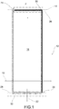
- Figure 1 shows a sliding lifting fitting according to an embodiment of this invention, which is indicated as item 12.
- the fitting 12 comprises a frame 14 and at least one leaf 16, which can move with respect to frame 14 between a sliding position and a closed position in a sliding direction 18.
- the fitting can also comprise at least one fixed leaf.
- fitting 12 can also comprise more than one leaf 16, movable with respect to the frame, such as fitting 12 which can be made with two movable leafs 16.
- the fitting 12 comprises support means 20 for supporting at least one leaf 16 while sliding on frame 14.
- support means 20 are capable of:
- the fitting 12 further comprises locking means 24 for pushing leaf 16 in locking direction 22 from the closed position to the locking position.
- the closed position is understood as the position in which leaf 16 is closed but can slide.
- frame 14 comprises an upper guide 26 for an upper profile 30 of leaf 16 and/or a lower guide 28 for a lower profile 32 of leaf 16.
- Guides 26 and 28 are adapted to allow leaf 16 to slide in sliding direction 18.
- upper and lower are understood as the positions of two opposing edges of the leaf or frame with respect to the plane on which the fitting sits.
- frame 14 comprises an upper guide 26 for an upper profile 30.
- support means 20 may comprise two permanent magnets in which: a first permanent magnet is placed at lower profile 32 of leaf 16 and a second permanent magnet is placed at lower guide 28 of frame 14 so that their poles align and repel each other. In this case leaf 16 stays lifted by the guide on the frame thanks to the magnetic force of repulsion.
- magnetic levitation supports may be used for this purpose, such as active magnetic levitation, dynamic magnetic levitation, or passive magnetic levitation based on permanent magnets using attraction or repulsion.
- support means 20 can comprise at least one support carriage designed to slide on a corresponding lower guide and to resiliently support the leaf.
- the carriage can be installed with springs that allow for movement in the locking direction.
- the springs can be: helical springs, air springs, or other resilient elements.
- support means 20 can be of the pneumatically actuated type.
- frame 14 comprises an upper guide 26 for an upper profile 30.
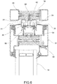
- upper guide 26 can have an upside-down-U cross-section designed to contain at least partially upper profile 30 of said leaf.
- the upper profile of the leaf can comprise an element 31, for example a box structure, designed to contain support means 20 at least partially. Between element 31 in the form of, for example, a box and the guide with an upside-down-U cross-section gaskets 33 and 35 may be placed.
- box element 31 can have shapes other than that shown, for example it may be an element provided with a certain thickness in which a recess may be placed to accommodate the elements indicated above.
- element 31 can be made, for example, of wood, PVC, aluminum, steel, etc.
- upper profile 30 of leaf 16 can be installed with at least one carriage 48, adapted to be contained at least partially in said lower guide 26 shaped like an upside-down-U.
- locking means 24 can be arranged on upper profile 30 or on the lower profile of said leaf 16. In the embodiments shown in the enclosed figures, locking means 24 are installed at upper profile 30.
- locking means 24 can be adapted to increase the distance between upper guide 26 placed on frame 14 and corresponding upper profile 30 of leaf 16.
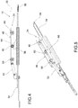
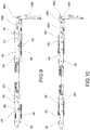
- locking means 24 comprise at least one carriage 48 designed to slide on upper guide 26 of frame 14.
- Carriage 48 is connected to a control bracket 50 by means of arm 52.
- Control bracket 50 can move in a direction parallel to upper profile 30 of leaf 16.
- Locking means 24 further comprise a fixed bracket 54 on which is placed a wedge element 56 designed to interact with carriage 48 to vary the distance of carriage 48 from upper profile 30 of leaf 16.
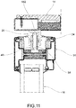
- carriage 48 can comprise a lifting wheel 62, designed to roll on wedge 56 as a result of a movement of control bracket 50 with respect to fixed bracket 54.
- carriage 48 can comprise two guide wheels 58 and 60 designed to roll with respect to upper guide 26 of frame 14.
- Guide wheels 58, 60 can be aligned in the direction of upper profile 30 of leaf 16.
- guide wheels 58, 60 can have a shape so as to conform to a corresponding rail 582 on upper guide 26.
- the wheel can have a curved concave shape so as to conform to a convex rail designed to be received at least partially by the curved convex shape of the wheel.
- lifting wheel 62 can be aligned with guide wheels 58, 60 and placed between them.
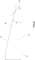
- wedge element 56 can comprise a sloped surface 64 between:
- sloped surface 64 of wedge 56 can comprise two sections:
- slope ⁇ can be between 35° and 55°, advantageously in the vicinity of 45°. According to a possible embodiment, slope ⁇ can be between 10° and 20°, advantageously in the vicinity of 15.5°.
- First section 66 defines the travel of carriage 48 from a position of rest to a position of contact with upper guide 26 of frame 14.
- control bracket 50 can be actuated by means of a hardware mechanisms 70 of fitting 12, which can be actuated by a casement bolt.
- carriage 48 can be moved by means of an articulated mechanism 482.
- wedge element 56 is secured at upper profile 30 of leaf 16.
- Carriage 48 is connected at one end to an arm of mechanism 484 which is in turn connected to crank 486.
- Crank 486 is connected by means of a hinge to actuation element 488 adapted to move along a lateral edge of the leaf.
- the operation of the articulated mechanism makes it possible, through a movement of actuation element 488, to move carriage 48 along the upper profile of the leaf in a similar way as seen earlier.
- actuation element 488 is moved downward, that is, away from wedge 56, crank 486 follows the movement of actuation element 488 and aligns with it, moving carriage 48 along the upper profile of the leaf and therefore the lifting wheel along wedge element 56.
- locking means 24 can comprise a plurality of carriages 48 and corresponding wedge elements 56, aligned and distributed along said upper profile 30 of leaf 16.
- the locking means can be motorized and actuated by means of a switch.
- locking means 24 can be placed at lower profile 32 of leaf 16 and be designed to interact with lower guide 26 of frame 14.
- support means 20 can be placed at upper guide 26 of frame 14.
- the sliding lifting fitting reduces the effort required to actuate the system compared to systems of the prior art.
- Its operation consists in moving the leaf from an initial closed position to a final locking position, at a lower level than the initial level, thus ensuring proper operation of the gaskets.
- the movement for locking takes place by means of suitable devices secured to the leaf, which, by acting with an opposing vertical force against the frame, exert a downward vertical thrust, moving the leaf in a vertical direction with respect to the state of equilibrium corresponding to a lifted leaf, allowing the desired closed position of the leaf to be reached.
- this mechanism is activated by means of a casement bolt that converts the rotary motion of the handle into a linear motion of the strip hardware.
- the combination of the lengthwise hardware, angle transmissions, and extensions placed in the slot of the leaf profile transfers the motion of the casement bolt to the devices exerting the lowering force on the leaf.
- hardware mechanism 70 can also serve the function of moving a set of perimeter pawls secured to the hardware which, by means of their engaging with special gripping indentations made in the frame, lock the leaf.
- the devices exerting the downward force can be activated by controlled mechatronic systems, pneumatic pistons, or other manually- or automatically-controlled actuation systems.
- carriage 48 raises the level of the carriage which, going against the upper frame by means of its two end wheels, generates a thrust that causes the desired vertical movement of the leaf.
- the sloped surface on which the center wheel of the carriage runs is made with a dual slope: the first section with a marked slope so as to complete the distance between the rest position and the position of the carriage in contact with the upper frame, with a short travel of the handle; the second section with a milder slope so that the increase in height, and the corresponding thrust of the upper frame, is gradual and does not excessively stress the mechanisms of the hardware, so as to minimize the force required to draw the carriage.
- Actuation of the handle results in a lowering/locking of the leaf, contrary to what happens in a sliding lifting fitting of the prior art. It follows that, depending on the mechanical feature of the resilient support, the force required to move the leaf vertically by the required amount of travel is less than the force of the weight of the entire leaf.
- the force needed on the handle to move the door from the closed position to the locking position is substantially less compared to systems of the prior art thanks to the particular resilient curve of the system which reduces the force for the required section of travel.
Landscapes
- Engineering & Computer Science (AREA)
- Mechanical Engineering (AREA)
- Window Of Vehicle (AREA)
- Power-Operated Mechanisms For Wings (AREA)
Applications Claiming Priority (1)
| Application Number | Priority Date | Filing Date | Title |
|---|---|---|---|
| IT102019000003581A IT201900003581A1 (it) | 2019-03-12 | 2019-03-12 | Serramento ad alzante scorrevole |
Publications (1)
| Publication Number | Publication Date |
|---|---|
| EP3708752A1 true EP3708752A1 (fr) | 2020-09-16 |
Family
ID=66776757
Family Applications (1)
| Application Number | Title | Priority Date | Filing Date |
|---|---|---|---|
| EP20162577.9A Pending EP3708752A1 (fr) | 2019-03-12 | 2020-03-12 | Ferrure pour élément à soulèvement et coulissement |
Country Status (2)
| Country | Link |
|---|---|
| EP (1) | EP3708752A1 (fr) |
| IT (1) | IT201900003581A1 (fr) |
Citations (3)
| Publication number | Priority date | Publication date | Assignee | Title |
|---|---|---|---|---|
| AU4711985A (en) * | 1984-09-19 | 1986-03-27 | Jamison Door Company | Horizontal sliding door |
| EP1312743A2 (fr) * | 2001-11-20 | 2003-05-21 | Gretsch-Unitas GmbH Baubeschläge | Dispositif de blocage pour un vantail coulissant et levant; ferrure du type crémone avec un tel dispositif; porte ou fenêtre coulissante et levante avec un tel dispositif |
| EP2310600A1 (fr) * | 2008-06-17 | 2011-04-20 | GSG INTERNATIONAL S.p.A. | Porte ou fenêtre coulissante |
-
2019
- 2019-03-12 IT IT102019000003581A patent/IT201900003581A1/it unknown
-
2020
- 2020-03-12 EP EP20162577.9A patent/EP3708752A1/fr active Pending
Patent Citations (4)
| Publication number | Priority date | Publication date | Assignee | Title |
|---|---|---|---|---|
| AU4711985A (en) * | 1984-09-19 | 1986-03-27 | Jamison Door Company | Horizontal sliding door |
| EP1312743A2 (fr) * | 2001-11-20 | 2003-05-21 | Gretsch-Unitas GmbH Baubeschläge | Dispositif de blocage pour un vantail coulissant et levant; ferrure du type crémone avec un tel dispositif; porte ou fenêtre coulissante et levante avec un tel dispositif |
| EP2310600A1 (fr) * | 2008-06-17 | 2011-04-20 | GSG INTERNATIONAL S.p.A. | Porte ou fenêtre coulissante |
| EP2310600B1 (fr) * | 2008-06-17 | 2012-05-30 | GSG INTERNATIONAL S.p.A. | Porte ou fenêtre coulissante |
Also Published As
| Publication number | Publication date |
|---|---|
| IT201900003581A1 (it) | 2020-09-12 |
Similar Documents
| Publication | Publication Date | Title |
|---|---|---|
| KR102060564B1 (ko) | 양문형 슬라이딩 도어 시스템 | |
| EP2494133B1 (fr) | Structure de porte coulissante comportant des portes coulissantes et des portes pivotantes | |
| EP0075364B2 (fr) | Dispositif de support et de course pour portes coulissantes notamment pour des meubles | |
| US7744035B2 (en) | Door for compartment of the baggage-compartment type | |
| GB2162225A (en) | Sliding door mechanism | |
| KR102058734B1 (ko) | 스크류 구동제어 시스템 | |
| KR20190098182A (ko) | 롤링 베어링 가이드를 갖는 변위 장치 | |
| MX2012009773A (es) | Puerta levadiza que tiene una guia de hoja de puerta movil. | |
| EP3430220B1 (fr) | Dispositif d'actionnement pour un ouvrant d'une fenêtre ou porte coulissante | |
| FI3963159T3 (fi) | Liukuovi käsittäen liukuvan ovilevyn | |
| EP3708752A1 (fr) | Ferrure pour élément à soulèvement et coulissement | |
| KR101060234B1 (ko) | 미서기 창호 시스템의 개폐 장치 | |
| JP6780016B2 (ja) | 家具駆動装置 | |
| RU2720388C1 (ru) | Устройство для уплотнения, по меньшей мере, одной дверной створки для рельсового транспортного средства (варианты) и рельсовое транспортное средство | |
| KR20100120035A (ko) | 미닫이 도어 조립체 | |
| EP3615754B1 (fr) | Agencement de porte coulissante | |
| EP1970514B1 (fr) | Porte ou fenêtre coulissante | |
| US11828106B2 (en) | Slat system and case furniture | |
| EP2402534B1 (fr) | Dispositif de guide inférieur de mur pour porte coulissante | |
| WO2019179853A1 (fr) | Ensemble d'entraînement pour système de porte coulissante | |
| KR100753579B1 (ko) | 시스템창호 개폐장치 | |
| KR102010371B1 (ko) | 슬라이딩 창호용 완충장치 | |
| JP2000000696A (ja) | 鉛直型ベイリングプレス用のシャフトドア | |
| US11384579B2 (en) | Sliding door arrangement | |
| CN220365485U (zh) | 一种可调节门轮支架 |
Legal Events
| Date | Code | Title | Description |
|---|---|---|---|
| PUAI | Public reference made under article 153(3) epc to a published international application that has entered the european phase |
Free format text: ORIGINAL CODE: 0009012 |
|
| STAA | Information on the status of an ep patent application or granted ep patent |
Free format text: STATUS: THE APPLICATION HAS BEEN PUBLISHED |
|
| AK | Designated contracting states |
Kind code of ref document: A1 Designated state(s): AL AT BE BG CH CY CZ DE DK EE ES FI FR GB GR HR HU IE IS IT LI LT LU LV MC MK MT NL NO PL PT RO RS SE SI SK SM TR |
|
| AX | Request for extension of the european patent |
Extension state: BA ME |
|
| STAA | Information on the status of an ep patent application or granted ep patent |
Free format text: STATUS: REQUEST FOR EXAMINATION WAS MADE |
|
| 17P | Request for examination filed |
Effective date: 20210302 |
|
| RBV | Designated contracting states (corrected) |
Designated state(s): AL AT BE BG CH CY CZ DE DK EE ES FI FR GB GR HR HU IE IS IT LI LT LU LV MC MK MT NL NO PL PT RO RS SE SI SK SM TR |
|
| STAA | Information on the status of an ep patent application or granted ep patent |
Free format text: STATUS: EXAMINATION IS IN PROGRESS |
|
| 17Q | First examination report despatched |
Effective date: 20230823 |