EP3709208A1 - Procédé et unité de commande pour la détection d'une région d'intérêt - Google Patents
Procédé et unité de commande pour la détection d'une région d'intérêt Download PDFInfo
- Publication number
- EP3709208A1 EP3709208A1 EP19162875.9A EP19162875A EP3709208A1 EP 3709208 A1 EP3709208 A1 EP 3709208A1 EP 19162875 A EP19162875 A EP 19162875A EP 3709208 A1 EP3709208 A1 EP 3709208A1
- Authority
- EP
- European Patent Office
- Prior art keywords
- vehicle
- environment sensor
- environment
- interest
- region
- Prior art date
- Legal status (The legal status is an assumption and is not a legal conclusion. Google has not performed a legal analysis and makes no representation as to the accuracy of the status listed.)
- Withdrawn
Links
Images


Classifications
-
- G—PHYSICS
- G06—COMPUTING OR CALCULATING; COUNTING
- G06V—IMAGE OR VIDEO RECOGNITION OR UNDERSTANDING
- G06V40/00—Recognition of biometric, human-related or animal-related patterns in image or video data
- G06V40/10—Human or animal bodies, e.g. vehicle occupants or pedestrians; Body parts, e.g. hands
- G06V40/18—Eye characteristics, e.g. of the iris
-
- G—PHYSICS
- G06—COMPUTING OR CALCULATING; COUNTING
- G06F—ELECTRIC DIGITAL DATA PROCESSING
- G06F18/00—Pattern recognition
- G06F18/20—Analysing
- G06F18/24—Classification techniques
- G06F18/243—Classification techniques relating to the number of classes
- G06F18/2431—Multiple classes
-
- G—PHYSICS
- G06—COMPUTING OR CALCULATING; COUNTING
- G06N—COMPUTING ARRANGEMENTS BASED ON SPECIFIC COMPUTATIONAL MODELS
- G06N3/00—Computing arrangements based on biological models
- G06N3/02—Neural networks
- G06N3/04—Architecture, e.g. interconnection topology
- G06N3/0464—Convolutional networks [CNN, ConvNet]
-
- G—PHYSICS
- G06—COMPUTING OR CALCULATING; COUNTING
- G06N—COMPUTING ARRANGEMENTS BASED ON SPECIFIC COMPUTATIONAL MODELS
- G06N3/00—Computing arrangements based on biological models
- G06N3/02—Neural networks
- G06N3/08—Learning methods
-
- G—PHYSICS
- G06—COMPUTING OR CALCULATING; COUNTING
- G06N—COMPUTING ARRANGEMENTS BASED ON SPECIFIC COMPUTATIONAL MODELS
- G06N3/00—Computing arrangements based on biological models
- G06N3/02—Neural networks
- G06N3/08—Learning methods
- G06N3/09—Supervised learning
-
- G—PHYSICS
- G06—COMPUTING OR CALCULATING; COUNTING
- G06V—IMAGE OR VIDEO RECOGNITION OR UNDERSTANDING
- G06V10/00—Arrangements for image or video recognition or understanding
- G06V10/40—Extraction of image or video features
- G06V10/44—Local feature extraction by analysis of parts of the pattern, e.g. by detecting edges, contours, loops, corners, strokes or intersections; Connectivity analysis, e.g. of connected components
- G06V10/443—Local feature extraction by analysis of parts of the pattern, e.g. by detecting edges, contours, loops, corners, strokes or intersections; Connectivity analysis, e.g. of connected components by matching or filtering
- G06V10/449—Biologically inspired filters, e.g. difference of Gaussians [DoG] or Gabor filters
- G06V10/451—Biologically inspired filters, e.g. difference of Gaussians [DoG] or Gabor filters with interaction between the filter responses, e.g. cortical complex cells
- G06V10/454—Integrating the filters into a hierarchical structure, e.g. convolutional neural networks [CNN]
-
- G—PHYSICS
- G06—COMPUTING OR CALCULATING; COUNTING
- G06V—IMAGE OR VIDEO RECOGNITION OR UNDERSTANDING
- G06V10/00—Arrangements for image or video recognition or understanding
- G06V10/70—Arrangements for image or video recognition or understanding using pattern recognition or machine learning
- G06V10/82—Arrangements for image or video recognition or understanding using pattern recognition or machine learning using neural networks
-
- G—PHYSICS
- G06—COMPUTING OR CALCULATING; COUNTING
- G06V—IMAGE OR VIDEO RECOGNITION OR UNDERSTANDING
- G06V20/00—Scenes; Scene-specific elements
- G06V20/50—Context or environment of the image
- G06V20/56—Context or environment of the image exterior to a vehicle by using sensors mounted on the vehicle
-
- G—PHYSICS
- G06—COMPUTING OR CALCULATING; COUNTING
- G06V—IMAGE OR VIDEO RECOGNITION OR UNDERSTANDING
- G06V20/00—Scenes; Scene-specific elements
- G06V20/50—Context or environment of the image
- G06V20/56—Context or environment of the image exterior to a vehicle by using sensors mounted on the vehicle
- G06V20/58—Recognition of moving objects or obstacles, e.g. vehicles or pedestrians; Recognition of traffic objects, e.g. traffic signs, traffic lights or roads
-
- G—PHYSICS
- G06—COMPUTING OR CALCULATING; COUNTING
- G06V—IMAGE OR VIDEO RECOGNITION OR UNDERSTANDING
- G06V20/00—Scenes; Scene-specific elements
- G06V20/50—Context or environment of the image
- G06V20/56—Context or environment of the image exterior to a vehicle by using sensors mounted on the vehicle
- G06V20/58—Recognition of moving objects or obstacles, e.g. vehicles or pedestrians; Recognition of traffic objects, e.g. traffic signs, traffic lights or roads
- G06V20/582—Recognition of moving objects or obstacles, e.g. vehicles or pedestrians; Recognition of traffic objects, e.g. traffic signs, traffic lights or roads of traffic signs
-
- G—PHYSICS
- G05—CONTROLLING; REGULATING
- G05D—SYSTEMS FOR CONTROLLING OR REGULATING NON-ELECTRIC VARIABLES
- G05D1/00—Control of position, course, altitude or attitude of land, water, air or space vehicles, e.g. using automatic pilots
- G05D1/0088—Control of position, course, altitude or attitude of land, water, air or space vehicles, e.g. using automatic pilots characterized by the autonomous decision making process, e.g. artificial intelligence, predefined behaviours
-
- G—PHYSICS
- G05—CONTROLLING; REGULATING
- G05D—SYSTEMS FOR CONTROLLING OR REGULATING NON-ELECTRIC VARIABLES
- G05D1/00—Control of position, course, altitude or attitude of land, water, air or space vehicles, e.g. using automatic pilots
- G05D1/02—Control of position or course in two dimensions
- G05D1/021—Control of position or course in two dimensions specially adapted to land vehicles
- G05D1/0212—Control of position or course in two dimensions specially adapted to land vehicles with means for defining a desired trajectory
Definitions
- the present document generally relates to a method and/or a control unit and/or a system for analyzing sensor data of an environment sensor of a vehicle.
- the method and/or the control unit and/or the system may determine a region of interest based on the sensor data from the environment sensor of the vehicle.
- a conventional advanced driver assistance system for a vehicle may include an environment sensor.
- resolution of the environment sensor often exceeds processing power of the conventional system. In turn, this results in restricting sensing capabilities of the environment sensor.
- the environment sensor may be a plurality of sensors.
- the conventional system may attempt to process all of the information captured by the plurality of sensors. Each sensor in the plurality of sensors may be treated equally. This may also result in a data overload condition, such that the information to be processed exceeds the processing capabilities of the conventional system. This may result in performance issues for the conventional system.
- a system for a vehicle includes an environment sensor configured to capture environment sensor data regarding an environment of the vehicle. Furthermore, the system includes a control unit which is configured to determine a region of interest based on the environment sensor data and based on a machine-learned predictor. The machine-learned predictor may be configured to identify within the environment sensor data a region as the region of interest. The identified region being the region of interest may at least statistically coincide with a line of sight of an occupant, such as a human driver, of the vehicle.
- the control unit is configured to operate the vehicle or a component of the vehicle in dependence of the determined region of interest.
- a vehicle such as a one-track or two track road vehicle
- the vehicle may be a car, a bus, a truck or a motorcycle.
- an apparatus configured to provide a machine-learned predictor.
- the machine-learned predictor is configured to indicate a region of interest within environment sensor data captured by an environment sensor of a vehicle.
- the apparatus is configured to determine training data comprising a plurality of training data sets.
- a training data set comprises environmental training data captured by an environment sensor of a vehicle at a particular time instant and a projection of a line of sight of an occupant, such as a human driver, of the vehicle, at the particular time instant, onto the environmental training data.
- the apparatus is configured to train the machine-learned predictor using the training data.
- the apparatus may provide the machine-learned predictor for use within a second vehicle.
- a method for operating a vehicle includes an environment sensor configured to capture environment sensor data regarding an environment of the vehicle.
- the method comprises capturing environment sensor data using the environment sensor.
- the method comprises determining a region of interest based on the environment sensor data and based on a machine-learned predictor.
- the machine-learned predictor is configured to identify within the environment sensor data a region as the region of interest.
- the identification of the region as the region of interest may at least statistically coincide with a line of sight of an occupant, such as a human driver, of the vehicle.
- the method comprises operating the vehicle in dependence of the determined region of interest.
- a method for providing a machine-learned predictor configured to indicate a region of interest within environment sensor data captured by an environment sensor of a vehicle includes determining training data comprising a plurality of training data sets.
- a training data set comprises environmental training data captured by an environment sensor of a vehicle at a particular time instant and a projection of a line of sight of an occupant, such as a human driver, of the vehicle, at the particular time instant, onto the environmental training data.
- the method comprises training the machine-learned predictor using the training data.
- the method may also provide the machine-learned predictor for use within a second vehicle.
- Fig. 1 shows example components of a vehicle 10.
- the vehicle comprises one or more environment sensors 12, 13, 14, which are configured to capture environment sensor data indicative of the environment of the vehicle 10.
- the environment may include the surroundings around the vehicle 10.
- the vehicle 10 may comprise a camera 12 configured to provide video or camera data, a radar sensor 13 configured to provide radar data and/or a lidar sensor 14 configured to provide lidar data.
- the camera 12, the radar sensor 13, and the lidar sensor 14 are examples of the one or more environment sensors 12, 13, 14.
- a control unit 11 of the vehicle 10 may be configured to operate one or more actuators 15 of the vehicle 10 in dependence of the sensor data of the one or more environment sensors 12, 13, 14. Based on the environment sensor data, the control unit 11 may send a control signal to the one or more actuators 15. The control signal may cause the one or more actuators 15 to operate, such as to perform an action. The control signal may include command instructions to cause the one or more actuators 15 to operate, such as to perform the action.
- Example actuators 15 are a propulsion motor or engine, a braking system and/or a steering system of the vehicle 10. The actuators 15 may be configured to provide forward and/or sideways control of the vehicle 10. Hence, the control unit 11 may be configured to control the one or more actuators 15, in order to perform the forward and/or sideways control of the vehicle 10 at least partially in an autonomous manner (e.g. to provide an (advanced) driver assistance system).
- control unit 11 may be configured to analyze the environment sensor data of the one or more environment sensors 12, 13, 14, in order to detect one or more objects within the environment of the vehicle 10.
- the one or more objects may be classified according to one of a plurality of different object classes or object types.
- Example object classes or types are: a moving object, e.g. a preceding or trailing vehicle traveling on a road within the environment of the vehicle 10, a cyclist traveling on a road, in a lane, within the environment of the vehicle 10, a pedestrian walking in a crosswalk within the environment of the vehicle 10, etc., or a static object, e.g. a building, a traffic sign etc.
- the moving object classification may include objects designed to freely move, even if currently at rest, such as a vehicle parked in a parking spot, a cyclist stopped at a stop sign, a pedestrian standing on a street corner, etc.
- the one or more actuators 15 may be controlled in dependence of the position and/or of the type or class of the detected one or more objects, e.g. in order to maintain a space cushion with the detected one or more objects.
- the detection and the classification of an object based on environment sensor data is typically a processing intensive task.
- the sensor data may describe the environment of the vehicle 10 within a field of view 22 of the environment sensor 12, as illustrated in Fig. 2 .
- a camera 12 may be configured to capture camera data of a defined zone within the environment of the vehicle 10.
- the object detection may be performed in two steps.
- the environment sensor data may be analyzed (coarsely), in order to identify one or more regions of interest within the complete field of view 22 of the environment sensor 12.
- a region proposal network may be used for this task.
- the one or more regions of interest may be the sub-areas within the field of view 22 of the environment sensor 12, which most likely contain an object.
- a region of interest may be analyzed in further detail, in order to verify whether the region of interest contains an object. Furthermore, the type or class of object contained within the region of interest may be determined. Object detection and/or classification within a confined region of interest may be performed in an efficient and reliable manner, e.g. using a trained neural network.
- FIG. 2 illustrates an example driver 20, notably the head of a driver 20.
- the driver 20 When driving a vehicle 10, the driver 20 typically turns his or her line of sight 21 (and by consequence his or her field of view 23) towards the most relevant region 24 within the environment of the vehicle 10, e.g. in order to look at a particular object 25 within this particular region 24.
- the driver's line of sight 21 may be considered to be a reliable indicator of a relevant region 24 of interest within the environment of a vehicle 10.
- the vehicle 10 may comprise a driver sensor 17, such as a driver camera, which is configured to capture driver sensor data with regards to the driver 20 of the vehicle 10.
- the driver sensor 17 may be arranged within the vehicle 10 to face the driver 20.
- the driver sensor 17 may be arranged to capture driver sensor data regarding the eyes of the driver 20.
- the control unit 11 may be configured to determine the line of sight 21 of the driver 20 based on the driver sensor data. It should be noted that such a driver sensor 17 is only required for capturing training data for training a machine-learned predictor 16. Hence, a high precision sensor 17 may be used. Subsequent to training the machine-learned predictor 16, the machine-learned predictor 16 may be used within a vehicle 10 that does not comprise a driver sensor 17.
- the vehicle 10 may have access to the machine-learned predictor 16 (e.g. stored on a storage unit of the vehicle 10 and/or operated on the control unit 11 of the vehicle 10), wherein the machine-learned predictor 16 is configured to automatically determine one or more regions 24 of interest, based on the environment sensor data provided by one or more environment sensors 12, 13, 14 of the vehicle 10.
- the machine-learned predictor 16 may have been trained using training data which is indicative of the line of sights 21 of human drivers 20 during manual driving of the vehicle 10.
- the training data may comprise a plurality of training data sets, wherein a training data set indicates for a particular driving situation at a particular time instant,
- the machine-learned predictor 16 may comprise an artificial neural network 30 that has been trained using the training data.
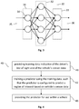
- Fig. 3 illustrates an example neural network 30 comprising an input layer 31, one or more hidden layers 32 and an output layer 33.
- Each of the layers 31, 32, 33 comprises one or more artificial neurons 34.
- a neuron 34 typically comprises one or more neuron parameters, such as a weight and/or an offset, as well as an activation function.
- the neuron parameters of a neural network 30 may be trained using a training algorithm, such as the backpropagation algorithm.
- the neural network 30 may receive as input an input vector 35 which is indicative of the environment sensor data describing a particular traffic situation within the environment of a vehicle 10. On the other hand, the neural network 30 may provide as an output an output vector 36 which is indicative of at least one or exactly one region of interest 24 within the corresponding environment sensor data.
- the neural network 30 may be trained using the plurality of training data sets.
- the neural network 30 may be trained by setting the neuron parameters of the neural network 30 such that in average for each of the plurality of training data sets, a deviation of the predicted region of interest 24 from the region of interest 24 indicated by the training data set is reduced, notably minimized.
- the predicted region of interest 24 may correspond to the region of interest which is provided as output vector 36 of the neural network 30 when providing as input vector 35 the environment sensor data of a training data set.
- an iterative training algorithm such as the backpropagation algorithm, may be used to achieve this goal.
- the method learns from an occupant of a vehicle, such as human driver, to identify the information within environment sensor data that is relevant within a particular driving situation.
- the method is configured to automatically identify one or more regions of interest 24, e.g. based on a camera image of the vehicle camera 12.
- an eye-tracking system 17 may be used on test drivers 20 (in order to detect the driver's line of sight 21) while collecting environment sensor data, such as from front facing camera images of the vehicle camera 12.
- the eye-tracking information as well as the corresponding sensor information may be collected as training data sets. For this purpose, capturing of the driver sensor data (for eye-tracking) and capturing of the environment sensor data should be time synchronized.
- the eye-tracking information (e.g. the line of sight 21 of the driver 20) may be projected into a corresponding image of the front facing camera system 12.
- calibration parameters i.e. pose data
- 3D information regarding the environment based on visual odometry, lidar (light detection and ranging), etc., may be used.
- a training data set indicates as input the sensor data captured by the environment sensor 12 (e.g. the front facing camera system) and indicates as output or label the information from the eye-tracking system 17 projected into the camera image (i.e. the region of interest 24 within the camera image, which corresponds to the line of sight 21 of the driver 20).
- the training of the neural network 30 i.e. of the machine-learned predictor 16) using the training data may be performed offline.
- the machine-learned predictor 16 comprising the neural network 30 may be used as follows: A current camera image captured by the camera 12 may be provided as input. The machine-learned predictor 16 may then provide as an output the region of interest 24 within this camera image. In particular, the machine-learned predictor 16 may indicate the region 24 within the camera image that a human driver 20 would have looked at (statistically, e.g. in average or in more than 50% of the cases).
- the region of interest 24 which is provided by the machine-learned predictor 16 may be further processed by a subsequent detection system or algorithm, in order to detect an object 25 within the region of interest 24.
- the detection system or algorithm may comprise a convolutional neural network (CNN) and/or a microcontroller leveraging techniques such as HOGs (histogram of oriented gradients), or algorithms and/or techniques from OpenCV (Open Source Computer Vision Library), etc.
- CNN convolutional neural network
- HOGs hoverogram of oriented gradients
- OpenCV Open Source Computer Vision Library
- the machine-learned predictor 16 and/or neural network 30 for detecting relevant regions of interest 24 may be used as input for other types of environment sensors 13, 14, such as a radar sensor 13 and/or a lidar sensor 14.
- the control unit 11 may be configured to operate a radar sensor 13 and/or a lidar sensor 14 in a focused manner, based on a relevant region of interest 24.
- the radar sensor 13 and/or the lidar sensor 14 may be instructed to capture environment sensor data only within the relevant region of interest 24 or with an increased resolution within the relevant region of interest 24. By doing this, the sensing capability of the vehicle 10 may be further increased.
- the machine-learned predictor 16, notably the neural network 30, may be trained for one or more different types of environment sensors 12, 13, 14 (alone or in combination).
- the line of sight 21 of a human driver 20, which is provided by the driver sensor 17, may be projected onto the environment sensor data of a camera 12, of a radar sensor 13 and/or of a lidar sensor 14, thereby providing labeled training data from a camera 12, from a radar sensor 13 and/or from a lidar sensor 14.
- the labeled training data for the different types of environment sensors 12, 13, 14 may be used to train separate machine-learned predictors 16, notably separate neural networks 30, for the different types of environment sensors 12, 13, 14.
- a combined machine-learned predictor 16 may be trained using as input a combination of the environment sensor data from (possibly all) different types of environment sensors 12, 13, 14. By making use of different types of environment sensors 12, 13, 14 the sensing capability of a vehicle 10 may be further increased.
- the region of interest 24 provided by a machine-learned predictor 16 may be used for a perception task.
- the region of interest 24 may be used as a basis for functional decision making within the vehicle 10, e.g. as a basis for making a functional decision within a driver assistance system.
- the region of interest 24 may be used to decide on whether or not an overtaking maneuver is initiated.
- the overtaking maneuver may be used when the vehicle 10 is a trailing vehicle. As the trailing vehicle, the vehicle 10 may be directly behind a preceding vehicle. Through the overtaking maneuver, the vehicle 10 may change lanes and accelerate to pass the preceding vehicle. From there, the vehicle 10 may change lanes again, such that the vehicle 10 is now the preceding vehicle directly in front of what was previously the preceding vehicle.
- the region of interest 24 provided by a machine-learned predictor 16 may be used directly as a model element or model object within an environment model used by the vehicle 10.
- the behavioral decision making of the vehicle 10 may directly take into account the region of interest 24 provided by a machine-learned predictor 16.
- the vehicle speed may be adapted automatically depending on the location of the region of interest 24.
- the region of interest 24 may be used for path planning of the vehicle's path.
- a method which learns regions of interests 24 for (possibly fully or partially autonomous) vehicles 10 by training a neural network 30 which uses eye-tracking information as ground truth, i.e. for labeling training data, in conjunction with sensor data from a camera 12 and/or a radar sensor 13 and/or a lidar sensor 14. It should be noted that no manual labeling is necessary for providing the training data, as the labels for the environment sensor data are collected in an automatic manner during test drives.
- the trained neural network 30 may be used for object detection during operation of a vehicle 10. Alternatively, or in addition, the trained neural network 30 may be used for focusing the sensing of environment sensors 12, 13, 14 such as cameras 12, lidar sensors 14 or radar sensors 13. The regions of interest 24 provided by the trained neural network 30 may be integrated within an environmental model of the vehicle 10 (e.g. for path planning of the vehicle 10).
- the regions of interest 24 provided by the trained neural network 30 may be used for determining a complexity measure indicative of the complexity of a driving situation.
- a sequence of regions of interest 24 may be determined for a corresponding sequence of time instants, wherein the sequence of regions of interest 24 is determined based on a corresponding sequence of environment sensor data captured at the corresponding sequence of time instants.
- the sequence of regions of interest 24 may be analyzed.
- a spatial and/or temporal distribution of the sequence of regions of interest 24 may be determined.
- a relatively fast change of the regions of interest 24 may indicate a relatively complex driving situation (as the eye of the driver 20 which is modelled by the neural network 30 jumps rapidly between different regions of interest 24).
- Fig. 4 shows a flow chart of an example method 40 for providing a machine-learned predictor 16 configured to indicate a region of interest 24 within environment sensor data captured by an environment sensor 12, 13, 14 of a vehicle 10.
- the method 40 may be executed by an apparatus (e.g. by a server or a computer).
- the method 40 may be executed offline.
- the method 40 may be executed online within a vehicle 10 (e.g. during a training phase).
- the method 40 may be used to adapt a vehicle 10 to the viewing habits of an occupant, notably a driver, of a particular vehicle. By doing this, the behavior of the vehicle 10 may be adapted to the particular driver 20.
- the method 40 comprises determining 41 training data comprising a plurality of training data sets.
- a training data set (notably each training data set) may comprise environmental training data captured by an environment sensor 12, 13, 14 of a vehicle 10 at a particular time instant.
- the training data set may comprise (as a label) a projection of a line of sight 21 of a human driver 20 of the vehicle 10 at the particular time instant onto the environmental training data.
- the training data set may indicate as a label which area of the environmental training data the driver 20 looked at, at the particular time instant.
- the method 40 may comprise (for determining a training data set) capturing environment sensor data using the environment sensor 12, 13, 14 of a vehicle 10 at the particular time instant. Furthermore, driver sensor data regarding the driver 20 of the vehicle 10 may be captured at the particular time instant, using a driver sensor 17 (e.g. a camera) of the vehicle 10. The line of sight 21 of the driver 20 at the particular time instant may then be determined based on the driver sensor data. Furthermore, a training data set may be determined based on the environment sensor data at the particular time instant and based on the line of sight 21 of the driver 20 at the particular time instant.
- the method 40 may comprise determining pose data regarding a pose of the environment sensor 12, 14, 16 and a pose of the driver sensor 17.
- a geometrical relationship between the pose of the environment sensor 12, 14, 16 and the pose of the driver sensor 17 may be determined.
- a projection of the line of sight 21 of the driver 20 at the particular time instant onto the environment sensor data at the particular time instant may then be determined based on the pose data.
- training data sets for training a machine-learned projector 16 may be provided in an efficient manner during manual driving activity of one or more drivers 20.
- the method 40 comprises training 42 the machine-learned predictor 16 using the training data.
- the machine-learned predictor 16 may be trained such that the machine-learned predictor 16 is configured to identify within environment sensor data of an environment sensor 12, 13, 14 of a vehicle 10 a region as a region of interest 24 that at least statistically coincides with the line of sight 21 of the human driver 20.
- the line of sight 21 of human drivers 20 within a particular driving situation may be distributed according to a particular probability distribution (e.g. a normal distribution with a particular variance around a mean or expectation value).
- the probability distribution of the line of sight 21 may (implicitly) be represented by the training data.
- the machine-learned predictor 16 may be trained such that the region which is provided and/or identified by the machine-learned predictor 16 corresponds (with an inaccuracy of ⁇ 10% or less) to the expectation or mean value of the probability distribution of the line of sight 21 of human drivers 20 within the particular driving situation (which is represented by the environment sensor data).
- the machine-learned predictor 16 may be trained such that the region which is provided and/or identified by the machine-learned predictor 16 corresponds to the line of sight 21 of human drivers 20 in 40% or more, 50% or more, or 60% or more of the cases.
- the machine-learned predictor 16 may comprise an artificial neural network 30 comprising a plurality of artificial neurons 34 arranged in multiple layers 31, 32, 33. Training 42 the machine-learned predictor 16 may comprise determining neuron parameters of the plurality of neurons 34 of the neural network 30 using the training data. For this purpose, a training algorithm, such as the backpropagation algorithm, may be used.
- a machine-learned predictor 16 of the line of sight 24 of a human driver 20 may be provided, wherein the machine-learned predictor 16 (at least statistically and/or in average) mimics the behavior of one or more human drivers 20 (the behavior of the one or more human drivers 20 being reflected within the training data).
- the machine-learned predictor 16 may be provided 43 for use within the vehicle 10, thereby increasing the sensing capabilities of the vehicle 10.
- the machine-learned predictor 16 may be provided for use within one or more other vehicles.
- the environment sensor 12, 13, 14 of the vehicle 10 may comprise one or more of: the camera 12, the radar sensor 13 and/or the lidar sensor 14.
- a sensor-type specific, machine-learned predictor 16 may be trained and provided.
- a machine-learned predictor 16 may be provided which makes use of the environment sensor data of multiple types of environment sensors 12, 13, 14 for predicting a region of interest 24.
- the use of multiple types of environment sensors 12, 13, 14 for detecting a region of interest 24 further increases the sensing capabilities of a vehicle 10.
- Fig. 5 shows a flow chart of an example method 50 for operating a vehicle 10.
- the method 50 may be executed by a control unit 11 of the vehicle 10.
- the vehicle 10 comprises an environment sensor 12, 13, 14 configured to capture environment sensor data regarding an environment of the vehicle 10.
- Example environment sensors 12, 13, 14 are a camera 12, a radar sensor 13 and/or a lidar sensor 14.
- the method 50 may be executed repeatedly at a sequent of time instants.
- the method 50 comprises, at a given time instant, determining 51 environment sensor data for the given time instant.
- the environment sensor data may describe a particular area of the environment of the vehicle 10 at the given time instant.
- the method comprises determining 52 a region of interest 24 based on the environment sensor data and based on a machine-learned predictor 16.
- the machine-learned predictor 16 may have been designed and/or trained using the method 40 described herein.
- the machine-learned predictor 16 may be configured to identify within the environment sensor data a region as the region of interest 24 that at least statistically and/or in average coincides with a line of sight 21 of an occupant, notably a human driver 20, of the vehicle 10.
- the machine-learned predictor 16 may indicate which sub-region within the environment sensor data a human driver 20 would (at least statistically and/or in average) look at.
- the indicated sub-region may correspond to the expectation value of the line of sight 21 of human drivers 20.
- the machine-learned predictor 16 may comprise or may be an artificial neural network 30, notably a convolutional neural network.
- the machine-learned predictor 16 may have been trained using training data comprising a plurality of training data sets captured during manual driving performed by a human driver 20.
- a training data set (notably each training data set) of the training data may comprise environmental training data captured at a particular time instant and a projection of the line of sight 21 of the human driver 20 at the particular time instant onto the environmental training data.
- the method 50 may comprise operating 53 the vehicle 10 in dependence of the determined region of interest 24.
- analysis of the environment sensor data may be focused on the determined region of interest 24, thereby increasing the sensing capability of a vehicle 10 in an efficient and reliable manner.
- the method 50 may comprise determining a corresponding sequence of environment sensor data for a sequence of time instants. Furthermore, a corresponding sequence of regions of interest 24 may be determined based on the sequence of environment sensor data and based on the machine-learned predictor 16. By doing this, the most relevant region of interest 24 may be updated in a continuous manner for continuous operation of the vehicle 10.
- the method 50 may comprise determining a complexity measure indicative of the complexity of a driving situation (which occurs at the sequence of time instants), based on the sequence of regions of interest 24, notably based on a spatial and/or temporal distribution of the sequence of regions of interest 24.
- the vehicle 10 may then be operated in dependence of the complexity measure.
- a handover from autonomous driving to manual driving may be initiated in dependence of (a value of) the complexity measure, thereby increasing the comfort and safety of a vehicle 10.
- the method 50 may comprise detecting and/or classifying an object 25 within the determined region of interest 24 using an object detection algorithm.
- the vehicle 10 may then be operated in a reliable manner in dependence of the position and/or the type of the detected object 25.
- the vehicle 10 may comprise a first environment sensor 12 (e.g. of a first type) configured to capture first environment data regarding a particular area of the environment of the vehicle 10 and a second environment sensor 14 (e.g. of a different second type) configured to capture second environment data regarding the particular area of the environment of the vehicle 10.
- a first environment sensor 12 e.g. of a first type
- a second environment sensor 14 e.g. of a different second type
- the method 50 may comprise determining the region of interest 24 based on the first environment data. Furthermore, the method 50 may comprise controlling the second environment sensor 14 in dependence of the determined region of interest 24, notably in order to selectively increase the resolution of the second environment sensor 14 within the determined region of interest 24 and/or in order to limit capturing of second environment data to the determined region of interest 24. Hence, the determined region of interest 24 may be used for focusing the operation of a different environment sensor 14, thereby further increasing the sensing capabilities of a vehicle 10.
- the determined region of interest 24 may be used directly as an additional virtual object within an environmental model of the vehicle 10.
- path planning of a path of the vehicle 10 may be performed (directly) in dependence of the determined region of interest 24.
- a driving parameter of the vehicle 10 notably a driving speed of the vehicle 10
- an advanced driver assistance system of the vehicle 10 may be provided and/or operated in dependence of the determined region of interest 24. Hence, the comfort and security of a vehicle 10 may be improved.
- the vehicle 10 may comprise a first environment sensor 12 of a first type, configured to capture first environment data regarding the environment of the vehicle 10, and a second environment sensor 14 of a second type, configured to capture second environment data regarding the environment of the vehicle 10.
- the method 50 may comprise determining first environment sensor data using the first environment sensor 12 and determining second environment sensor data using the second environment sensor 14.
- the method 50 may comprise determining a first region of interest 24 based on the first environment sensor data and based on a first machine-learned predictor 16, wherein the first machine-learned predictor 16 is configured to identify within the first environment sensor data a region as the first region of interest 24 that at least statistically and/or in average coincides with a line of sight 21 of a human driver 20.
- the method 50 may comprise determining a second region of interest 24 based on the second environment sensor data and based on a second machine-learned predictor 16, wherein the second machine-learned predictor 16 is configured to identify within the second environment sensor data a region as the second region of interest 24 that at least statistically and/or in average coincides with a line of sight 21 of human drivers 20.
- different machine-learned predictors 16 may be provided for different types of environment sensors 12, 14.
- the vehicle 10 may then be operated in dependence of the determined first and second region of interest 24, thereby increasing the comfort and/or security of a vehicle 10.
- the method 50 may comprise determining a region of interest 24 based on the first environment sensor data, the second environment data and based on the machine-learned predictor 16, wherein the machine-learned predictor 16 is configured to identify within the first and the second environment sensor data a region as the region of interest 24 that at least statistically and/or in average coincides with a line of sight 21 of human drivers 20.
- a machine-learned predictor 16 may be provided which is configured to predict a region of interest 24 based on the sensor data of multiple types of environment sensors 12, 13, 14, thereby further increasing the sensing capability of a vehicle 10.
- the schemes outlined in the present document enable a vehicle 10 to identify relevant regions of interest 24 in an efficient and reliable manner. This may be achieved by making use of the experience and/or of the viewing behavious of human drivers 20. Furthermore, the complexity of a traffic situation may be analyzed in an efficient and reliable manner. This information may e.g. be used for triggering a hand-over from autonomous driving to manual driving.
Landscapes
- Engineering & Computer Science (AREA)
- Theoretical Computer Science (AREA)
- Physics & Mathematics (AREA)
- General Physics & Mathematics (AREA)
- Evolutionary Computation (AREA)
- Multimedia (AREA)
- General Health & Medical Sciences (AREA)
- Health & Medical Sciences (AREA)
- Artificial Intelligence (AREA)
- Life Sciences & Earth Sciences (AREA)
- Data Mining & Analysis (AREA)
- Computing Systems (AREA)
- Software Systems (AREA)
- Biomedical Technology (AREA)
- Molecular Biology (AREA)
- Computer Vision & Pattern Recognition (AREA)
- General Engineering & Computer Science (AREA)
- Computational Linguistics (AREA)
- Biophysics (AREA)
- Mathematical Physics (AREA)
- Medical Informatics (AREA)
- Biodiversity & Conservation Biology (AREA)
- Databases & Information Systems (AREA)
- Human Computer Interaction (AREA)
- Ophthalmology & Optometry (AREA)
- Bioinformatics & Cheminformatics (AREA)
- Bioinformatics & Computational Biology (AREA)
- Evolutionary Biology (AREA)
- Traffic Control Systems (AREA)
Priority Applications (2)
| Application Number | Priority Date | Filing Date | Title |
|---|---|---|---|
| EP19162875.9A EP3709208A1 (fr) | 2019-03-14 | 2019-03-14 | Procédé et unité de commande pour la détection d'une région d'intérêt |
| US16/819,087 US11238319B2 (en) | 2019-03-14 | 2020-03-14 | Method and control unit for detecting a region of interest |
Applications Claiming Priority (1)
| Application Number | Priority Date | Filing Date | Title |
|---|---|---|---|
| EP19162875.9A EP3709208A1 (fr) | 2019-03-14 | 2019-03-14 | Procédé et unité de commande pour la détection d'une région d'intérêt |
Publications (1)
| Publication Number | Publication Date |
|---|---|
| EP3709208A1 true EP3709208A1 (fr) | 2020-09-16 |
Family
ID=65812233
Family Applications (1)
| Application Number | Title | Priority Date | Filing Date |
|---|---|---|---|
| EP19162875.9A Withdrawn EP3709208A1 (fr) | 2019-03-14 | 2019-03-14 | Procédé et unité de commande pour la détection d'une région d'intérêt |
Country Status (2)
| Country | Link |
|---|---|
| US (1) | US11238319B2 (fr) |
| EP (1) | EP3709208A1 (fr) |
Families Citing this family (5)
| Publication number | Priority date | Publication date | Assignee | Title |
|---|---|---|---|---|
| US20210064030A1 (en) * | 2019-08-27 | 2021-03-04 | Yu-Sian Jiang | Driver assistance for a vehicle and method for operating the same |
| US20210248442A1 (en) * | 2020-02-11 | 2021-08-12 | Distech Controls Inc. | Computing device and method using a neural network to predict values of an input variable of a software |
| US11328591B1 (en) * | 2021-01-25 | 2022-05-10 | Ford Global Technologies, Llc | Driver assistance system for drivers using bioptic lenses |
| US20230048304A1 (en) * | 2021-08-13 | 2023-02-16 | Humanising Autonomy Limited | Environmentally aware prediction of human behaviors |
| US20240059284A1 (en) * | 2022-08-22 | 2024-02-22 | Ford Global Technologies, Llc | Lane-based vehicle control |
Family Cites Families (31)
| Publication number | Priority date | Publication date | Assignee | Title |
|---|---|---|---|---|
| US20090079830A1 (en) * | 2007-07-27 | 2009-03-26 | Frank Edughom Ekpar | Robust framework for enhancing navigation, surveillance, tele-presence and interactivity |
| US7924146B2 (en) * | 2009-04-02 | 2011-04-12 | GM Global Technology Operations LLC | Daytime pedestrian detection on full-windscreen head-up display |
| US9720412B1 (en) * | 2012-09-27 | 2017-08-01 | Waymo Llc | Modifying the behavior of an autonomous vehicle using context based parameter switching |
| WO2014152339A1 (fr) * | 2013-03-14 | 2014-09-25 | Robert Bosch Gmbh | Affichages graphiques adaptés à l'environnement et au temps pour des systèmes d'informations de conducteur et d'assistance au conducteur |
| US20150112731A1 (en) * | 2013-10-18 | 2015-04-23 | State Farm Mutual Automobile Insurance Company | Risk assessment for an automated vehicle |
| US20160236088A1 (en) * | 2013-12-23 | 2016-08-18 | Hong C. Li | Provision of a virtual environment based on real time data |
| US10783587B1 (en) * | 2014-02-19 | 2020-09-22 | Allstate Insurance Company | Determining a driver score based on the driver's response to autonomous features of a vehicle |
| WO2016132295A1 (fr) * | 2015-02-19 | 2016-08-25 | Francesco Ricci | Système de guidage et de commande automatique pour véhicules |
| US20160314224A1 (en) * | 2015-04-24 | 2016-10-27 | Northrop Grumman Systems Corporation | Autonomous vehicle simulation system |
| WO2017052690A1 (fr) * | 2015-09-24 | 2017-03-30 | Intel Corporation | Contrôle de congestion pour services de « véhicule vers tout » |
| US10460600B2 (en) * | 2016-01-11 | 2019-10-29 | NetraDyne, Inc. | Driver behavior monitoring |
| US10650621B1 (en) * | 2016-09-13 | 2020-05-12 | Iocurrents, Inc. | Interfacing with a vehicular controller area network |
| US10012993B1 (en) * | 2016-12-09 | 2018-07-03 | Zendrive, Inc. | Method and system for risk modeling in autonomous vehicles |
| US10452926B2 (en) * | 2016-12-29 | 2019-10-22 | Uber Technologies, Inc. | Image capture device with customizable regions of interest |
| US10754348B2 (en) * | 2017-03-28 | 2020-08-25 | Uatc, Llc | Encoded road striping for autonomous vehicles |
| US10168697B2 (en) * | 2017-03-31 | 2019-01-01 | At&T Intellectual Property I, L.P. | Assistance for an autonomous vehicle using crowd-sourced responses |
| US10210672B2 (en) * | 2017-04-07 | 2019-02-19 | Toyota Research Institute, Inc. | Systems and methods for remotely controlling data collection by a vehicle |
| WO2018204544A1 (fr) * | 2017-05-02 | 2018-11-08 | The Regents Of The University Of Michigan | Trafic de véhicule simulé pour véhicules autonomes |
| US10386856B2 (en) * | 2017-06-29 | 2019-08-20 | Uber Technologies, Inc. | Autonomous vehicle collision mitigation systems and methods |
| US10883844B2 (en) * | 2017-07-27 | 2021-01-05 | Waymo Llc | Neural networks for vehicle trajectory planning |
| WO2019027889A1 (fr) * | 2017-08-02 | 2019-02-07 | Bae Systems Information And Electronic Systems Integration Inc. | Système et procédé de reconstruction d'incident utilisant des communications v2x |
| US10803325B2 (en) * | 2017-11-15 | 2020-10-13 | Uatc, Llc | Autonomous vehicle lane boundary detection systems and methods |
| US11061402B2 (en) * | 2017-11-15 | 2021-07-13 | Uatc, Llc | Sparse convolutional neural networks |
| WO2019136479A1 (fr) * | 2018-01-08 | 2019-07-11 | The Regents On The University Of California | Suivi de véhicules environnants et prédiction de mouvement |
| DE102018101513A1 (de) * | 2018-01-24 | 2019-07-25 | Valeo Schalter Und Sensoren Gmbh | Verfahren zur Detektion von Garagenparkplätzen |
| US10823572B2 (en) * | 2018-04-05 | 2020-11-03 | Symbol Technologies, Llc | Method, system and apparatus for generating navigational data |
| US20190318050A1 (en) * | 2018-04-11 | 2019-10-17 | Toyota Research Institute, Inc. | Environmental modification in autonomous simulation |
| CN109165606B (zh) * | 2018-08-29 | 2019-12-17 | 腾讯科技(深圳)有限公司 | 一种车辆信息的获取方法、装置以及存储介质 |
| US10740986B2 (en) * | 2018-08-30 | 2020-08-11 | Qualcomm Incorporated | Systems and methods for reconstructing a moving three-dimensional object |
| US10928819B2 (en) * | 2018-10-29 | 2021-02-23 | Here Global B.V. | Method and apparatus for comparing relevant information between sensor measurements |
| US12517511B2 (en) * | 2019-02-05 | 2026-01-06 | Nvidia Corporation | Combined prediction and path planning for autonomous objects using neural networks |
-
2019
- 2019-03-14 EP EP19162875.9A patent/EP3709208A1/fr not_active Withdrawn
-
2020
- 2020-03-14 US US16/819,087 patent/US11238319B2/en active Active
Non-Patent Citations (1)
| Title |
|---|
| ANDREA PALAZZI ET AL: "Predicting the Driver's Focus of Attention: the DR(eye)VE Project", ARXIV.ORG, CORNELL UNIVERSITY LIBRARY, 201 OLIN LIBRARY CORNELL UNIVERSITY ITHACA, NY 14853, 6 June 2018 (2018-06-06), XP081407879 * |
Also Published As
| Publication number | Publication date |
|---|---|
| US11238319B2 (en) | 2022-02-01 |
| US20200293815A1 (en) | 2020-09-17 |
Similar Documents
| Publication | Publication Date | Title |
|---|---|---|
| US11238319B2 (en) | Method and control unit for detecting a region of interest | |
| Fang et al. | Is the pedestrian going to cross? answering by 2d pose estimation | |
| CN111050116B (zh) | 利用时间递归网络进行在线动作检测的系统和方法 | |
| Bonnin et al. | Pedestrian crossing prediction using multiple context-based models | |
| Ohn-Bar et al. | On surveillance for safety critical events: In-vehicle video networks for predictive driver assistance systems | |
| JP5132750B2 (ja) | 運転者支援システムのための実世界の交通場面からの視覚特性の行動ベース学習 | |
| CN116872921A (zh) | 一种车辆规避风险方法、系统、车辆及存储介质 | |
| US20200211395A1 (en) | Method and Device for Operating a Driver Assistance System, and Driver Assistance System and Motor Vehicle | |
| US11308717B2 (en) | Object detection device and object detection method | |
| JP7210618B2 (ja) | 車両の周囲にある危険な対象物又は危険に晒されている対象物の迅速な識別 | |
| CN116209611B (zh) | 在自动驾驶中使用其他道路使用者对自我交通工具行为的反应的方法和系统 | |
| JP2015061776A (ja) | 予測的な先進運転支援システムの一貫性のある挙動生成 | |
| EP4004812A1 (fr) | Utilisation de données vidéo capturées pour identifier des signaux de virage actifs sur un véhicule | |
| KR20160135482A (ko) | 동적 장애물 움직임 예측 장치 및 그 방법 | |
| JP2022172444A (ja) | 原動機付き車両の走行動作を補助する方法及びアシスト装置並びに原動機付き車両 | |
| JP2021163432A (ja) | 信号灯状態識別装置、信号灯状態識別方法及び信号灯状態識別用コンピュータプログラムならびに制御装置 | |
| US11328602B2 (en) | System and method for navigation with external display | |
| US20220410931A1 (en) | Situational awareness in a vehicle | |
| US20210084227A1 (en) | Method and apparatus for the spatially resolved detection of an object outside a transportation vehicle with the aid of a sensor installed in a transportation vehicle | |
| Rajendar et al. | Prediction of stopping distance for autonomous emergency braking using stereo camera pedestrian detection | |
| US20210291825A1 (en) | Systems and methods for adapting activation of alerts according to curvature of a target path | |
| JP7755777B2 (ja) | コンピュータ実装方法、高度運転者支援システム、および車両 | |
| EP4372715A1 (fr) | Évaluation de menace de collision de véhicule | |
| JP2023037575A (ja) | 単眼2dセマンティックキーポイント検出および追跡 | |
| CN116977361A (zh) | 一种自动驾驶车辆轨迹预测方法及系统 |
Legal Events
| Date | Code | Title | Description |
|---|---|---|---|
| PUAI | Public reference made under article 153(3) epc to a published international application that has entered the european phase |
Free format text: ORIGINAL CODE: 0009012 |
|
| STAA | Information on the status of an ep patent application or granted ep patent |
Free format text: STATUS: THE APPLICATION HAS BEEN PUBLISHED |
|
| AK | Designated contracting states |
Kind code of ref document: A1 Designated state(s): AL AT BE BG CH CY CZ DE DK EE ES FI FR GB GR HR HU IE IS IT LI LT LU LV MC MK MT NL NO PL PT RO RS SE SI SK SM TR |
|
| AX | Request for extension of the european patent |
Extension state: BA ME |
|
| STAA | Information on the status of an ep patent application or granted ep patent |
Free format text: STATUS: THE APPLICATION IS DEEMED TO BE WITHDRAWN |
|
| 18D | Application deemed to be withdrawn |
Effective date: 20210317 |